JP2013500197A - Heavy vehicle tires with reinforced beads - Google Patents
Heavy vehicle tires with reinforced beads Download PDFInfo
- Publication number
- JP2013500197A JP2013500197A JP2012522144A JP2012522144A JP2013500197A JP 2013500197 A JP2013500197 A JP 2013500197A JP 2012522144 A JP2012522144 A JP 2012522144A JP 2012522144 A JP2012522144 A JP 2012522144A JP 2013500197 A JP2013500197 A JP 2013500197A
- Authority
- JP
- Japan
- Prior art keywords
- reinforcement
- anchoring structure
- axially
- radially
- tire
- Prior art date
- Legal status (The legal status is an assumption and is not a legal conclusion. Google has not performed a legal analysis and makes no representation as to the accuracy of the status listed.)
- Pending
Links
Images


Classifications
-
- B—PERFORMING OPERATIONS; TRANSPORTING
- B60—VEHICLES IN GENERAL
- B60C—VEHICLE TYRES; TYRE INFLATION; TYRE CHANGING; CONNECTING VALVES TO INFLATABLE ELASTIC BODIES IN GENERAL; DEVICES OR ARRANGEMENTS RELATED TO TYRES
- B60C15/00—Tyre beads, e.g. ply turn-up or overlap
- B60C15/0009—Tyre beads, e.g. ply turn-up or overlap features of the carcass terminal portion
- B60C15/0027—Tyre beads, e.g. ply turn-up or overlap features of the carcass terminal portion with low ply turn-up, i.e. folded around the bead core and terminating at the bead core
-
- B—PERFORMING OPERATIONS; TRANSPORTING
- B60—VEHICLES IN GENERAL
- B60C—VEHICLE TYRES; TYRE INFLATION; TYRE CHANGING; CONNECTING VALVES TO INFLATABLE ELASTIC BODIES IN GENERAL; DEVICES OR ARRANGEMENTS RELATED TO TYRES
- B60C15/00—Tyre beads, e.g. ply turn-up or overlap
- B60C15/06—Flipper strips, fillers, or chafing strips and reinforcing layers for the construction of the bead
-
- Y—GENERAL TAGGING OF NEW TECHNOLOGICAL DEVELOPMENTS; GENERAL TAGGING OF CROSS-SECTIONAL TECHNOLOGIES SPANNING OVER SEVERAL SECTIONS OF THE IPC; TECHNICAL SUBJECTS COVERED BY FORMER USPC CROSS-REFERENCE ART COLLECTIONS [XRACs] AND DIGESTS
- Y10—TECHNICAL SUBJECTS COVERED BY FORMER USPC
- Y10T—TECHNICAL SUBJECTS COVERED BY FORMER US CLASSIFICATION
- Y10T152/00—Resilient tires and wheels
- Y10T152/10—Tires, resilient
- Y10T152/10495—Pneumatic tire or inner tube
- Y10T152/10819—Characterized by the structure of the bead portion of the tire
- Y10T152/10837—Bead characterized by the radial extent of apex, flipper or chafer into tire sidewall
-
- Y—GENERAL TAGGING OF NEW TECHNOLOGICAL DEVELOPMENTS; GENERAL TAGGING OF CROSS-SECTIONAL TECHNOLOGIES SPANNING OVER SEVERAL SECTIONS OF THE IPC; TECHNICAL SUBJECTS COVERED BY FORMER USPC CROSS-REFERENCE ART COLLECTIONS [XRACs] AND DIGESTS
- Y10—TECHNICAL SUBJECTS COVERED BY FORMER USPC
- Y10T—TECHNICAL SUBJECTS COVERED BY FORMER US CLASSIFICATION
- Y10T152/00—Resilient tires and wheels
- Y10T152/10—Tires, resilient
- Y10T152/10495—Pneumatic tire or inner tube
- Y10T152/10855—Characterized by the carcass, carcass material, or physical arrangement of the carcass materials
- Y10T152/10864—Sidewall stiffening or reinforcing means other than main carcass plies or foldups thereof about beads
Landscapes
- Engineering & Computer Science (AREA)
- Mechanical Engineering (AREA)
- Tires In General (AREA)
Abstract
重車両用タイヤ(10)であって、ビード(50)の各々の中で周方向補強材(70)を有する繋留構造体(700)に繋留された半径方向カーカス補強材(60)を有し、
カーカス補強材(60)は、繋留構造体(700)に部分的に巻き付けられ、タイヤ(10)は、結合補強材(150)を更に有し、結合補強材は、カーカス補強材と接触状態にある第1の部分(151)を有し、結合補強材の延長部として、繋留構造体の半径方向外側に位置した端箇所(157)まで繋留構造体(700)と接触状態にある第2の部分(152)が設けられ、結合補強材の箇所は、繋留構造体の軸方向最も内側の箇所(702)と軸方向最も外側の箇所(704)との間で軸方向に配置され、タイヤ(10)は、結合補強材(150)を包囲した補剛補強材(160)を更に有し、補剛補強材は、繋留構造体(700)及び結合補強材の半径方向内側で延びており、補剛補強材(160)の軸方向外側の端箇所(166)は、周方向補強要素(70)の半径方向最も内側の箇所(73)から半径方向距離DRのところに配置され、半径方向距離DRは、周方向補強材(70)の半径方向最も内側の箇所(73)と半径方向最も外側の箇所(71)との間の半径方向距離DSの0.8倍以上であり且つ半径方向距離DSの1.2倍以下であることを特徴とするタイヤ。A heavy vehicle tire (10) having a radial carcass reinforcement (60) anchored to a tether (700) having a circumferential reinforcement (70) in each of the beads (50). ,
The carcass reinforcement (60) is partially wrapped around the anchoring structure (700), the tire (10) further comprises a coupling reinforcement (150), which is in contact with the carcass reinforcement. A second portion that has a first portion (151) and is in contact with the anchoring structure (700) as an extension of the binding reinforcement to an end location (157) located radially outward of the anchoring structure; The portion (152) is provided, and the location of the joint reinforcing material is arranged in the axial direction between the axially innermost location (702) and the axially outermost location (704) of the anchoring structure. 10) further comprises a stiffening reinforcement (160) surrounding the coupling reinforcement (150), which extends radially inward of the anchoring structure (700) and the coupling reinforcement, End portion (166) on the axially outer side of the stiffening reinforcement (160) The radial direction DR is disposed at a radial distance DR from the radially innermost point (73) of the circumferential reinforcing element (70), and the radial distance DR is the radially innermost point ( 73) and a radial distance DS between the radially outermost portion (71) of 0.8 times or more and 1.2 times or less of the radial distance DS.
Description
本発明は、半径方向カーカス補強材を有すると共に重車両に取り付けられるよう設計されたタイヤに関する。本発明は、特に、これらタイヤのビード構造体に関する。 The present invention relates to a tire having a radial carcass reinforcement and designed to be attached to a heavy vehicle. The present invention particularly relates to a bead structure for these tires.
重車両用タイヤは、クラウン部分を有し、クラウン部分の各側部の延長部として、ビードで終端するサイドウォールが設けられている。かかるタイヤは、特にカーカス補強材を含む複数の補強材を有し、カーカス補強材の役割は、タイヤの内部インフレーション圧力により生じる力に耐えることにある。このカーカス補強材は、タイヤのクラウン及びサイドウォール内に位置すると共にその端部がビード内に配置された適当な繋留構造体に繋留されている。カーカス補強材は、一般に、互いに平行に配置されると共に周方向とほぼ90°又は90°に等しい角度をなす複数の補強要素で構成されている(この場合、カーカス補強材は、「半径方向」であると呼ばれる)。カーカス補強材は、通常、半径方向外側に上曲がり又は巻き上げ部分を形成するために適当な周方向剛性を有する繋留構造体周りに上に曲げられ又は巻き付けられることにより繋留され、上曲がり部分の長さは、例えば繋留構造体の半径方向最も内側の箇所に関して測定して、使用中、タイヤに満足の行く耐久性をもたらすよう選択される。カーカス補強材の上曲がり部分と主部分との間には軸方向に、1つ又は2つ以上のエラストマーを主成分とする材料が設けられ、かかるエラストマーを主成分とする材料は、カーカス補強材の2つの部分相互間に機械的結合をもたらす。 The heavy vehicle tire has a crown portion, and a sidewall that terminates with a bead is provided as an extension of each side portion of the crown portion. Such a tire has a plurality of reinforcing materials, particularly including a carcass reinforcing material, and the role of the carcass reinforcing material is to withstand the force generated by the internal inflation pressure of the tire. The carcass reinforcement is anchored to a suitable anchoring structure that is located within the crown and sidewall of the tire and whose ends are disposed within the bead. A carcass reinforcement is generally composed of a plurality of reinforcing elements arranged parallel to each other and at an angle approximately equal to 90 ° or 90 ° with the circumferential direction (in this case, the carcass reinforcement is “radial” Is called). The carcass reinforcement is usually anchored by being bent or wrapped up around a tether structure having a suitable circumferential stiffness to form an upward bend or roll-up portion radially outward, and the length of the upper bend portion. The length is selected, for example, with respect to the radially innermost point of the anchoring structure and provides satisfactory durability for the tire during use. A material mainly composed of one or two or more elastomers is provided in the axial direction between the upper bent portion and the main portion of the carcass reinforcing material. This provides a mechanical coupling between the two parts.
使用の際、かかるタイヤは、ビードの半径方向最も内側の部分と接触関係をなすよう設計されたリム受座又はシート及びタイヤを取り付けてその通常圧力までインフレートさせたときにビードの軸方向位置を固定するリムフランジを有する取り付けリムに取り付けられる。 In use, such a tire is positioned in the axial position of the bead when a rim seat or seat designed to make contact with the radially innermost part of the bead and the tire is inflated to its normal pressure. Is attached to a mounting rim having a rim flange for fixing the rim.
タイヤが機械的転動応力に耐えるようにするため、特にカーカス補強材の上曲がり部分の少なくとも一部分に当てて配置されたプライの形態をした追加のビード補強材を設けることが慣例である。 It is customary to provide an additional bead reinforcement in the form of a ply, particularly in the form of a ply placed against at least a part of the upper bend of the carcass reinforcement in order for the tire to withstand mechanical rolling stresses.
転動中、タイヤビードは、これらビードがリムフランジ周りに巻き付けられているので(即ち、これらは、部分的に、フランジの幾何学的形状を採用しているので)多数回の曲げサイクルを受ける。この曲げの結果として、ビード補強材、特にカーカス補強材の上曲がり部分の張力の変化と組み合わされた状態の曲率の大きな又は小さな変化が生じる。これらサイクルは、ビードを構成する材料に圧縮力及び伸長力を生じさせる。転動中、カーカス補強材の補強要素の周期的周方向変位も又、タイヤのサイドウォールビードに見られる場合がある。周期的周方向変位は、この場合、かかる変位が車輪が回転するたびに平均平衡位置に関して一方向及び逆方向に生じることを意味している。 During rolling, the tire beads are subjected to multiple bending cycles because they are wrapped around the rim flange (ie, they partially adopt the flange geometry). . This bending results in a large or small change in curvature combined with a change in tension in the bend reinforcement, in particular the carcass reinforcement upper bend. These cycles produce compressive and stretching forces on the material making up the bead. During rolling, periodic circumferential displacement of the reinforcing elements of the carcass reinforcement may also be seen in the tire sidewall beads. Periodic circumferential displacement means in this case that such displacement occurs in one direction and in the opposite direction with respect to the average equilibrium position each time the wheel rotates.
転動は、ビードを構成する材料、特にエラストマー、更に特に補強材の端部(カーカス補強材の上曲がり部分の端部又は追加の補強材の端部)のすぐ近くに位置したエラストマーに応力及び/又は変形を生じさせる。これら応力及び/又は変形により、タイヤの有効寿命の多少なりとも相当な減少を生じさせる場合がある。 Rolling causes stress and stress on the material comprising the bead, in particular the elastomer, more particularly the elastomer located in the immediate vicinity of the end of the reinforcement (the end of the upper bend of the carcass reinforcement or the end of the additional reinforcement). Causes deformation. These stresses and / or deformations may cause a substantial decrease in the useful life of the tire.
これは、これら応力及び/又は変形が補強材の端部の近くに離脱及び亀裂を生じさせる場合があるからである。補強要素の半径方向の向き及び補強材を構成する補強要素(一般に、これらは、金属ケーブルである)の性状により、カーカス補強材の上曲がり部分の端部は、この現象に特に敏感である。 This is because these stresses and / or deformations can cause separation and cracking near the ends of the reinforcement. Due to the radial orientation of the reinforcement elements and the nature of the reinforcement elements that make up the reinforcement (generally these are metal cables), the ends of the upper bent portions of the carcass reinforcement are particularly sensitive to this phenomenon.
WO2006/013201‐A1という参照番号で公開された特許文献(国際公開第2006/013201(A1)号パンフレット)は、カーカス補強材がビードワイヤに部分的に巻き付けられることによりもはや上に曲げられず、ビードの各々内の繋留構造体周りに少なくとも丸一回転巻き付けられたタイヤビード構造体を記載している。このように、カーカス補強材の端部は、大きな周期的応力を受けないビードの領域内に配置され、かくして、ビードの耐久性を向上させることができる。 The patent document published under the reference number WO 2006 / 013201-A1 (WO 2006/013201 (A1) pamphlet) no longer bends up because the carcass reinforcement is partly wrapped around the bead wire. The tire bead structure wound at least once round around the anchoring structure in each of the above. In this way, the end portion of the carcass reinforcement is disposed in the bead region that is not subjected to a large periodic stress, and thus the durability of the bead can be improved.
しかしながら、かかるタイヤビード構造体は、機械的観点からは効果的であるが、それにもかかわらず、かかるタイヤビード構造体は、依然として高価であり、従来の工業的製造手段を用いて具体化するのが困難である。 However, although such tire bead structures are effective from a mechanical point of view, such tire bead structures are nevertheless expensive and can be implemented using conventional industrial manufacturing means. Is difficult.
異なる対策では、転動中、曲げ応力及び補強材の周方向運動に耐えるのに十分な剛性を有するビード構造体を提案することによりビード劣化の恐れの発生を阻止する手段が模索され、かかる手段は、具体化が容易であると共に工業的規模で製作するうえで経済的に魅力がある。 In different measures, a means for preventing the possibility of bead deterioration by seeking a bead structure with sufficient rigidity to withstand bending stresses and circumferential movement of the reinforcement during rolling is sought, and such means Is easy to materialize and economically attractive for manufacturing on an industrial scale.
WO2008/107234‐A1という参照番号で公開された特許文献(国際公開第2008/107234(A1)号パンフレット)は、かかるビード構造体を記載している。この特許文献は、トレッドを有する重車両タイヤを開示しており、トレッドの各側の横方向延長部として、取り付けリムに係合するよう設計されたビードで終端するサイドウォールが設けられている。加うるに、このタイヤは、周方向と少なくとも80°の角度をなす方向に差し向けられた複数の補強要素で作られた半径方向カーカス補強材を有している。 The patent document (WO 2008/107234 (A1) pamphlet) published under the reference number WO 2008 / 107234-A1 describes such a bead structure. This patent document discloses a heavy vehicle tire having a tread, with side walls terminating in beads designed to engage the mounting rim as lateral extensions on each side of the tread. In addition, the tire has a radial carcass reinforcement made of a plurality of reinforcing elements oriented in a direction that makes an angle of at least 80 ° with the circumferential direction.
このカーカス補強材は、ビードの各々の中で繋留構造体に繋留され、繋留構造体は、周方向補強材を有し、この周方向補強材の周りには被覆異形要素が形成され、その半径方向断面の周囲は、半径方向内側の部分及び半径方向外側の部分を有し、これら2つの部分は、被覆異形要素の周囲の2つの互いに軸方向最も遠くに離れたところで互いに交わっている。 The carcass reinforcement is anchored to the anchoring structure in each of the beads, and the anchoring structure has a circumferential reinforcement, around which the covering deformed element is formed and its radius The perimeter of the directional cross section has a radially inner portion and a radially outer portion, the two portions intersecting each other at the two axially furthest away points around the coated profile element.
さらに、このカーカス補強材は、タイヤの内側から外側に軸方向に延びた状態で一部が繋留構造体の被覆異形要素に巻き付けられ、このカーカス補強材の端は、被覆異形要素の周囲上又はその近くに配置されている。 Further, the carcass reinforcement is partially wound around the covering deformed element of the anchoring structure in a state of extending in the axial direction from the inside to the outside of the tire, and the end of the carcass reinforcing member is on the periphery of the covering deformable element or Located near it.
このタイヤは、周方向と70°以上の角度をなす方向に差し向けられた複数の補強要素で作られた第1の連結補強材を更に有している。この第1の連結補強材は、(i)半径方向最も外側の繋留構造体の被覆異形要素の周囲に対して半径方向外側の箇所と(ii)カーカス補強材の端箇所との間でカーカス補強材と接触状態にある第1の部分を有し、カーカス補強材の端部を越える第1の連結補強材の延長部として、被覆異形要素の周囲の半径方向外側の部分上に位置した箇所まで被覆異形要素と接触状態にある第2の部分が設けられている。 The tire further includes a first connection reinforcing member made of a plurality of reinforcing elements oriented in a direction that forms an angle of 70 ° or more with the circumferential direction. The first connecting reinforcing material is (i) a carcass reinforcement between a radially outer portion with respect to the periphery of the covering deformed element of the outermost anchoring structure in the radial direction and (ii) an end portion of the carcass reinforcing material. A first portion in contact with the material and as an extension of the first connecting reinforcement beyond the end of the carcass reinforcement, to a location located on the radially outer portion around the coated deformed element A second portion in contact with the coated profile element is provided.
このタイヤは、第1の連結補強材を包囲した第2の連結補強材をを有し、第2の連結補強材は、内側部分及び外側部分を形成するために第1の連結補強材の半径方向内側で被覆異形要素の下に延びており、内側部分は、カーカス補強材に対して軸方向内側に位置し、外側部分は、カーカス補強材の軸方向外側に位置し、内側部分は、第1の部分の第1の端箇所と第1の連結補強材の端箇所との間でカーカス補強材とゼロではない長さにわたって接触状態にあり、外側部分は、外側部分の1つの箇所から端箇所までゼロではない長さにわたってカーカス補強材と接触状態にあり、これら箇所は、第1の連結補強材の端箇所の半径方向外側に配置されている。 The tire has a second connection reinforcement that surrounds the first connection reinforcement, and the second connection reinforcement has a radius of the first connection reinforcement to form an inner portion and an outer portion. Extends inwardly under the covering profile element, the inner part is located axially inward with respect to the carcass reinforcement, the outer part is located axially outside of the carcass reinforcement and the inner part is The first portion of the first portion and the end portion of the first connecting reinforcement are in contact with the carcass reinforcement over a non-zero length, and the outer portion ends from one portion of the outer portion. The parts are in contact with the carcass reinforcing material over a non-zero length, and these parts are arranged radially outside the end part of the first connecting reinforcing material.
この第2の連結補強材は、周方向とせいぜい50°の角度をなす平均方向に差し向けられた複数の補強要素で形成されている。 The second connecting reinforcing member is formed of a plurality of reinforcing elements oriented in an average direction that forms an angle of at most 50 ° with the circumferential direction.
このタイヤのアーキテクチャを区別するものは、とりわけ、第2の連結補強材がビード繋留構造体周りに繋留され、それと同時に、繋留構造体の付近に位置決めされたカーカス補強材の端部と組み合わせ状態でこの補強材の各側でカーカス補強材に軸方向に結合されている。かかる構造体では、カーカス補強材の端部は、走行条件下においてかなり小さい大きさの応力及び変形を受ける領域内に保たれ、この端部は、更に、少なくとも第2の補強材で覆われている。 What distinguishes this tire architecture is that, inter alia, in combination with the end of the carcass reinforcement positioned near the anchoring structure, the second connecting reinforcement is anchored around the bead anchoring structure. Each side of the reinforcement is axially coupled to the carcass reinforcement. In such a structure, the end of the carcass reinforcement is kept in a region that is subjected to a considerably small amount of stress and deformation under running conditions, and this end is further covered with at least a second reinforcement. Yes.
かかるアーキテクチャにより、ビードの劣化を著しく減少させることができるが、繋留構造体の半径方向内側の亀裂開始応力の高い集中を受ける領域が依然として存在する。 While such an architecture can significantly reduce bead degradation, there are still regions that are subject to high concentrations of crack initiation stresses radially inward of the anchoring structure.
本発明の一目的は、ビード劣化の恐れを一段と減少させることにある。 An object of the present invention is to further reduce the risk of bead deterioration.
この目的は、カーカス補強材が自由端部を備えておらず、それにもかかわらず、曲げ力及び非ラジアル化(deradialisation )力に耐えるのに十分な剛性を有するビード補強材によって達成され、この剛性は追加の補強要素によりもたらされ、タイヤの軸方向外側に位置した追加の補強材の端部は、亀裂開始応力の集中を減少させるよう変形の小さな領域内に配置されている。 This object is achieved by means of a bead reinforcement whose rigidity is sufficient to withstand bending forces and deradialisation forces, although the carcass reinforcement does not have a free end. Is provided by an additional reinforcing element, and the end of the additional reinforcement located axially outside the tire is located in a region of low deformation so as to reduce the concentration of crack initiation stress.
具体的に言えば、この目的は、本発明の一観点によれば、リムに取り付けられるようになった重車両用タイヤであって、トレッドを載せたクラウン補強材を含むクラウンと、クラウンの半径方向内方の延長部としての2つのサイドウォールと、サイドウォールの半径方向内側に設けられていて、リムに係合するよう設計された2つのビードとを有し、各ビードは、繋留構造体を有し、繋留構造体は、周方向補強材を有し、繋留構造体は、任意の半径方向断面で見て、半径方向最も外側の箇所、軸方向最も内側の箇所及び軸方向最も外側の箇所を有し、タイヤは、周方向と80°以上の角度をなす方向に差し向けられた複数の補強要素を含む半径方向カーカス補強材を更に有し、カーカス補強材は、ビードの各々の中で、繋留構造体に繋留されており、カーカス補強材は、タイヤの内側から外側に軸方向に延びた状態で一部が繋留構造体に巻き付けられ、カーカス補強材の端箇所は、繋留構造体上に又はこの近くで且つ繋留構造体の軸方向最も内側の箇所と軸方向最も外側の箇所との間で軸方向に配置されていることを特徴とするタイヤによって達成される。 Specifically, the object is, according to one aspect of the present invention, to be a heavy vehicle tire adapted to be attached to a rim, including a crown including a crown reinforcement on which a tread is mounted, and a radius of the crown. Two side walls as inwardly extending portions and two beads provided radially inward of the side walls and designed to engage the rim, each bead being a tethered structure The anchoring structure has a circumferential reinforcing member, and the anchoring structure has a radially outermost position, an axially innermost position, and an axially outermost position when viewed in any radial cross section. The tire further includes a radial carcass reinforcement including a plurality of reinforcing elements oriented in a direction that forms an angle of 80 ° or more with the circumferential direction, the carcass reinforcement being disposed in each of the beads. And tethered to the tethered structure The carcass reinforcing material is partially wound around the anchoring structure in an axial direction from the inside to the outside of the tire, and the end portion of the carcass reinforcing material is on or near the anchoring structure and the anchoring structure. This is achieved by a tire characterized in that it is arranged in the axial direction between an axially innermost part and an axially outermost part of the body.
タイヤは、周方向と70°以上の角度をなす方向に差し向けられた複数の補強要素で形成された結合補強材を更に有し、結合補強材は、繋留構造体の半径方向最も外側の箇所に関して半径方向外側に位置した端箇所とカーカス補強材の端箇所との間でカーカス補強材と接触状態にある第1の部分を有し、カーカス補強材の端箇所を越える結合補強材の延長部として、繋留構造体の半径方向外側に位置した端箇所まで繋留構造体と接触状態にある第2の部分が設けられ、結合補強材の端箇所は、繋留構造体の軸方向最も内側の箇所と軸方向最も外側の箇所との間で軸方向に配置されている。 The tire further includes a joint reinforcing member formed of a plurality of reinforcing elements oriented in a direction that forms an angle of 70 ° or more with the circumferential direction, and the joint reinforcing member is a radially outermost portion of the anchoring structure. A first portion in contact with the carcass reinforcement between the end located radially outward with respect to the end of the carcass reinforcement and extending the joint reinforcement beyond the end of the carcass reinforcement As a second part in contact with the anchoring structure is provided up to the end located radially outside the anchoring structure, the end of the coupling reinforcement is the innermost part in the axial direction of the anchoring structure. It arrange | positions in an axial direction between the axially outermost locations.
タイヤは、結合補強材を包囲した補剛補強材を更に有し、補剛補強材は、軸方向内側部分及び軸方向外側部分を形成するよう繋留構造体及び結合補強材の半径方向内側で延びており、軸方向内側部分は、カーカス補強材に対して軸方向内側に位置し、軸方向外側部分は、カーカス補強材の軸方向外側に位置し、軸方向内側部分は、軸方向内側部分の端箇所と結合補強材の端箇所との間でカーカス補強材と距離LCにわたり接触状態にあり、軸方向内側部分の端箇所は、結合補強材の端箇所の半径方向外側に配置され、補剛補強材は、周方向と50°以下の角度をなす平均方向に差し向けられた複数の補強要素で作られている。 The tire further includes a stiffening reinforcement surrounding the coupling reinforcement, the stiffening reinforcement extending radially inward of the anchoring structure and the coupling reinforcement so as to form an axial inner portion and an axial outer portion. The axially inner portion is positioned axially inside the carcass reinforcement, the axially outer portion is positioned axially outside of the carcass reinforcement, and the axially inner portion is the axially inner portion of the carcass reinforcing material. The end portion and the end portion of the joint reinforcement member are in contact with the carcass reinforcement member over a distance LC, and the end portion of the inner portion in the axial direction is disposed radially outside the end portion of the joint reinforcement member and is stiffened. The reinforcement is made of a plurality of reinforcement elements oriented in an average direction that forms an angle of 50 ° or less with the circumferential direction.
補剛補強材の軸方向外側の端箇所は、繋留構造体の周方向補強要素の半径方向最も内側の箇所から半径方向距離DRのところに配置され、半径方向距離DRは、繋留構造体の周方向補強材の半径方向最も内側の箇所と半径方向最も外側の箇所との間の半径方向距離DSの0.8倍以上であり且つ繋留構造体の周方向補強材の半径方向最も内側の箇所と半径方向最も外側の箇所との間の半径方向距離DSの1.2倍以下である。 The axially outer end portion of the stiffening reinforcement is disposed at a radial distance DR from the radially innermost portion of the circumferential reinforcing element of the anchoring structure, and the radial distance DR is the circumference of the anchoring structure. A radial distance DS between the radially innermost point and the radially outermost point of the directional reinforcing material is not less than 0.8 times the radial distance DS and the radially innermost point of the circumferential reinforcing material of the anchoring structure; It is 1.2 times or less the radial distance DS between the radially outermost points.
補剛補強材の端部のこの配置場所により、補剛補強材の端部が受ける応力は、制限され、亀裂の発生は、極めて著しく遅くなる。 This location of the end of the stiffening stiffener limits the stress experienced by the end of the stiffening stiffener, and cracking is extremely slow.
特に、補剛補強材は、周方向と15°以上且つ30°以下の角度をなす平均方向に差し向けられた複数の補強要素で形成されることにより優れた結果が得られた。 In particular, excellent results were obtained when the stiffening reinforcing material was formed of a plurality of reinforcing elements oriented in an average direction forming an angle of 15 ° or more and 30 ° or less with the circumferential direction.
有利な実施形態によれば、繋留構造体は、周方向補強要素を包囲した被覆異形要素を含み、被覆異形要素の半径方向断面の周囲は、半径方向内側の部分及び半径方向外側の部分を有し、部分は、繋留構造体の軸方向最も内側及び軸方向最も外側の箇所のところで互いに交わる。カーカス補強材の端箇所は、被覆異形要素の周囲上又はその近くに配置されている。かかる被覆異形要素の存在により、一方において繋留構造体とカーカス補強材との間の付着が促進されると共に他方において繋留構造体と結合補強材との付着が促進される。 According to an advantageous embodiment, the anchoring structure comprises a coated profile element surrounding the circumferential reinforcing element, the circumference of the radial profile of the coated profile element having a radially inner part and a radially outer part. However, the portions cross each other at the axially innermost and axially outermost points of the anchoring structure. The end of the carcass reinforcement is arranged on or near the periphery of the coated profile element. Due to the presence of such a deformed profile element, adhesion between the anchoring structure and the carcass reinforcing material is promoted on the one hand, and adhesion between the anchoring structure and the joint reinforcing material is promoted on the other hand.
有利な実施形態によれば、補剛補強材の軸方向内側部分の接触長さLCは、補剛補強材の軸方向内側部分の半径方向最も外側の端箇所と繋留構造体の周方向補強要素の半径方向最も内側の箇所との間の距離DYの少なくとも20パーセントである。かくして、接触長さLCは、補剛補強材がホイールに取り付けられているタイヤのビード摩耗を生じさせる場合がある転動運動中におけるカーカス補強材の非ラジアル化運動に効果的に対抗するのに十分である。 According to an advantageous embodiment, the contact length LC of the axially inner part of the stiffening stiffener is the radial outermost end of the axially inner part of the stiffening stiffener and the circumferential reinforcing element of the anchoring structure Is at least 20 percent of the distance DY from the radially innermost point. Thus, the contact length LC effectively counteracts the non-radial motion of the carcass reinforcement during the rolling motion where the stiffening reinforcement may cause bead wear on the tire attached to the wheel. It is enough.
好ましくは、補剛補強材の軸方向内側部分の半径方向最も外側の端箇所と繋留構造体の周方向補強材の半径方向最も内側の箇所との間の距離DYは、カーカス補強材の半径方向最も外側の箇所とカーカス補強材の半径方向最も内側の箇所との間の半径方向距離DCの15パーセント以上且つ40パーセント以下である。かくして、補剛補強材の軸方向内側部分の半径方向最も外側の端箇所は、転動中、相当大きな曲げを受けるビード及びサイドウォールの領域から十分遠くに位置し、その結果、亀裂の生成が阻止される。 Preferably, the distance DY between the radially outermost end portion of the axially inner portion of the stiffening reinforcing member and the radially innermost portion of the circumferential reinforcing member of the anchoring structure is equal to the radial direction of the carcass reinforcing member. 15% or more and 40% or less of the radial distance DC between the outermost part and the radially innermost part of the carcass reinforcement. Thus, the radially outermost end of the axially inner portion of the stiffening stiffener is located far enough from the bead and sidewall regions that undergo significant bending during rolling, resulting in crack formation. Be blocked.
有利な実施形態によれば、結合補強材の補強要素は、テキスタイル性状の補強要素から選択され、それにより、繋留構造体周りのその巻き付けが大幅に容易になる。 According to an advantageous embodiment, the reinforcement element of the joint reinforcement is selected from a textile-like reinforcement element, which greatly facilitates its winding around the anchoring structure.
補剛補強材の軸方向内側部分を、軸方向内側部分の端箇所の近くの剪断応力を減少させるようカーカス補強材から局所的に隔てるのが有利であり、補強材相互間にはエラストマーが介在して設けられる。 Advantageously, the axially inner part of the stiffening reinforcement is locally separated from the carcass reinforcement to reduce the shear stress near the end of the axially inner part, with an elastomer between the reinforcements Provided.
有利には、補剛補強材は、各々が前記部分の各々をそれぞれ構成する2つの不連続部分で形成され、不連続部分は、重ね合わせ領域で互いにオーバーラップする。 Advantageously, the stiffening stiffener is formed of two discontinuous portions, each of which constitutes each of the portions, and the discontinuous portions overlap each other in the overlap region.
補剛補強材は、各々が部分の各々をそれぞれ構成する2つの不連続部分で形成され、不連続部分は、重ね合わせ領域で互いにオーバーラップしている場合、重ね合わせ領域は、繋留構造体の被覆異形要素の付近に配置され、任意の半径方向断面で見て、重ね合わせ領域の長さLKは、繋留構造体の互いに軸方向最も離れた箇所相互間の軸方向距離DAの少なくとも半分であるであるようにするのが有利である。 The stiffening reinforcement is formed of two discontinuous portions, each of which constitutes each of the portions. When the discontinuous portions overlap each other in the overlapping region, the overlapping region is the anchoring structure. Located in the vicinity of the covering profile element and viewed in any radial cross section, the length LK of the overlap region is at least half the axial distance DA between the axially furthest points of the anchoring structure. It is advantageous to ensure that
特定の実施形態によれば、結合補強材は、ビード繋留構造体の被覆異形要素とカーカス補強材との間に介在して設けられている。 According to a particular embodiment, the joint reinforcement is provided between the coated profile element of the bead anchoring structure and the carcass reinforcement.
当業者による「半径方向」という用語の幾つかの異なる使い方を区別することが重要である。まず第1に、この表現は、タイヤの半径を意味している。この意味では、箇所P1は、これが箇所P2よりもタイヤの回転軸線の近くに位置する場合、箇所P2「の内側に半径方向に」(又は箇所P2「の半径方向内側に」)位置すると呼ばれる。これとは逆に、箇所P3は、これが箇所P4よりもタイヤの回転軸線から遠くに位置する場合、箇所P4「の外側に半径方向に」(又は箇所P4「の半径方向外側に」)位置すると呼ばれる。進行が小さい半径(又は大きい半径)の方向に行われている場合、かかる進行は、「半径方向内方(又は半径方向外方)」に行われていると呼ばれる。半径方向距離に関する場合にも、かかる用語のこの意味が当てはまる。 It is important to distinguish several different uses of the term “radial” by those skilled in the art. First of all, this expression means the radius of the tire. In this sense, the location P1 is referred to as being located “radially inside the location P2” (or radially inward of the location P2) when it is located closer to the tire rotation axis than the location P2. On the contrary, when the position P3 is located farther from the tire rotation axis than the position P4, the position P3 is positioned "in the radial direction outside the position P4" (or the position P4 "outward in the radial direction"). be called. If the progression is in the direction of a small radius (or a large radius), such a progression is said to be “radially inward (or radially outward)”. This meaning of such terms also applies when referring to radial distance.
これとは対照的に、細線又は補強材は、細線又は補強材の補強要素が周方向と80°以上且つ90°以下の角度をなす場合に「半径方向」と呼ばれる。指定されるべきこととして、本明細書においては、「細線」という用語は、全く一般的な意味で理解されなければならず、細線は、細線の構成材料又はゴムとのその結合性を促進するために実施される表面処理とは無関係に、モノフィラメント、マルチフィラメント、ケーブル若しくはコード、もろより糸又はこれらと同等の集成体の形態をした細線を含む。 In contrast, a fine line or reinforcement is called “radial” when the reinforcement element of the fine line or reinforcement makes an angle of between 80 ° and 90 ° with the circumferential direction. As to be specified, in this specification, the term “thin wire” should be understood in a very general sense, and the fine wire promotes its binding properties to the constituent material of rubber or rubber. Regardless of the surface treatment carried out for this purpose, it includes fine wires in the form of monofilaments, multifilaments, cables or cords, crumbs or their equivalent assemblies.
最後に、「半径方向断面」という用語は、本明細書では、タイヤの回転軸線を含む平面に関する断面を意味している。 Finally, the term “radial cross section” means herein a cross section with respect to a plane containing the axis of rotation of the tire.
「軸方向」は、タイヤの回転軸線に平行な方向である。箇所P5は、これが箇所P6よりもタイヤの中間平面の近くに位置する場合、箇所P6「の内側に軸方向に」(又は箇所P6「の軸方向内側に」)位置すると呼ばれる。これとは逆に、箇所P7は、これが箇所P8よりもタイヤの中間平面から遠くに位置する場合、箇所P8「の外側に軸方向に」(又は箇所P8「の軸方向外側に」)位置すると呼ばれる。タイヤの「中間平面」は、タイヤの回転軸線に垂直であり且つ各ビードの環状補強構造体から等距離のところに位置する平面である。 The “axial direction” is a direction parallel to the rotation axis of the tire. The location P5 is said to be located “in the axial direction inside the location P6” (or in the axial direction inside the location P6) when it is located closer to the middle plane of the tire than the location P6. On the contrary, when the location P7 is located farther from the middle plane of the tire than the location P8, the location P8 is “in the axial direction outside the location P8” (or the location P8 “in the axial direction outside”). be called. The “midplane” of the tire is a plane that is perpendicular to the tire's axis of rotation and is equidistant from the annular reinforcing structure of each bead.
「周方向」は、タイヤの半径と軸方向の両方に対して垂直な方向である。「周方向断面」は、タイヤの回転軸線に垂直な平面に関する断面である。 The “circumferential direction” is a direction perpendicular to both the radius and the axial direction of the tire. The “circumferential cross section” is a cross section related to a plane perpendicular to the rotation axis of the tire.
「転動面」という用語は、本明細書においては、タイヤが転動しているとき、路面に接触する可能性があるタイヤのトレッドの箇所全てを意味している。 The term “rolling surface” as used herein refers to all the tread locations of a tire that may come into contact with the road surface when the tire is rolling.
「配合ゴム」という表現は、少なくともエラストマー及び充填剤を含むゴムコンパウンドを意味している。 The expression “compound rubber” means a rubber compound containing at least an elastomer and a filler.
図示の実施形態の説明を理解しやすくするため、同一の構造を有する要素を示すために同一の参照符号が用いられている。 To facilitate understanding of the description of the illustrated embodiment, the same reference numerals are used to denote elements having the same structure.
図1は、先行技術のタイヤ10の略図である。タイヤ10は、トレッド30を載せたクラウン補強材(図1では見えない)を含むクラウンと、クラウンの半径方向内方の延長部としての2つのサイドウォール40と、サイドウォール40の半径方向内側に設けられた2つのビード50とを有している。
FIG. 1 is a schematic illustration of a
図2は、先行技術の7イヤ10の概略部分斜視図であり、図2は、このタイヤの種々のコンポーネントを示している。タイヤ10は、配合ゴムで被覆された細線61から成るカーカス補強材60と、各々がタイヤ10をリム(図示せず)上に取り付けた状態に保持する周方向補強材(この場合、ビードワイヤ)70を含む2つのビード20とを有している。カーカス補強材60は、ビード50の各々に繋留されている。タイヤ10は、2枚のプライ80,90を含むクラウン補強材を更に有している。プライ80,90の各々は、各層中で平行であり且つ1つの層と次の層に関しクロス掛けされていて、周方向と10°〜70°の角度をなすフィラメント状補強要素81,91によって補強されている。タイヤは、クラウン補強材の半径方向外側に配置されたたが掛け補強材100を更に有し、このたが掛け補強材は、周方向に差し向けられると共に螺旋の状態に巻かれた補強要素101で構成されている。トレッド30がたが掛け補強材上に配置されており、タイヤ10が路面と接触するのは、このトレッド30によってである。図示のタイヤ10は、「チューブレス」タイヤであり、このタイヤは、インフレーションガスに対して不透過性であると共にタイヤの内面を覆うゴムコンパウンドで作られた「内側ライナ」110を有する。
FIG. 2 is a schematic partial perspective view of a prior art 7
図3は、サイズ295/60R22.5の本発明の一実施形態としてのタイヤ10の一部分の概略半径方向断面図である。このタイヤは、リム(図示せず)に取り付けられるよう設計された重車両タイヤである。タイヤ10は、補強プライ120,130相互間にサンドイッチされたプライ80,90で形成されたクラウン補強材を含むクラウンを有する。補強プライ120は、カーカス補強材60を圧縮から保護し、補強プライ130は、クラウン補強材を穴あけ及び衝撃から保護する。後者のプライ130の上にはトレッド30が載っている。タイヤ10は、クラウンの半径方向内方の延長部としての2つのサイドウォール40及びサイドウォールの半径方向内側に位置していて、リムに係合するよう設計された2つのビード50を更に有している。各ビードは、繋留構造体700を有し、この繋留構造体は、周方向補強材70を有する。この場合、補強材70は、複数本の周方向に巻かれた金属ワイヤで構成されているビードワイヤである。図4に示されているように、繋留構造体700は、任意の半径方向断面で見て、半径方向最も外側の箇所701、軸方向最も内側の箇所702及び軸方向最も外側の箇所704を有している。周方向補強材70の半径方向最も内側の箇所73及び半径方向最も外側の箇所71も又示されている。繋留構造体700の幾何学的形状が、複数の箇所が軸方向/半径方向最も内側/最も外側であると呼ばれるようなものである場合、これらの箇所のうち任意の1つを選択することができる。繋留構造体は、被覆異形要素75、この場合、ナイロン140/2ファブリックを更に有する。被覆異形要素75のナイロンコードは、10パーセント伸び率における弾性率(20℃における)が5MPaを超える配合ゴムで被覆されている。これらコードは、1mm間隔を置いて配置されると共に周方向と50°以上の角度をなす方向に差し向けられている。
FIG. 3 is a schematic radial cross-sectional view of a portion of a
タイヤ10は、寸法が18/100mmの多数本の要素細線で作られた複数本の金属ケーブルを含む半径方向カーカス補強材60を更に有している。これらケーブルは、配合ゴム内に埋め込まれると共に周方向と80°以上の角度をなす方向に差し向けられている。カーカス補強材60は、ビードの各々の中で繋留構造体700に繋留されており、具体的に言えば、カーカス補強材60は、タイヤの内側から外側に軸方向に延びた状態で部分的に繋留構造体700に巻き付けられている。かくして、カーカス補強材60は、被覆異形要素75の周囲の一部分の輪郭形状を辿り、被覆異形要素の構成材料の付着性又は粘着性によって被覆異形要素に機械的に結合されており、かかる材料は、カーカス補強材60の補強要素を被覆する。カーカス補強材60の端箇所65は、繋留構造体700上に又はこの近くで且つ繋留構造体の軸方向最も内側の箇所702と軸方向最も外側の箇所704との間で軸方向に配置されている。カーカス補強材の端箇所65が繋留構造体700の「近く」に配置されているといわれる場合、これは、端箇所65と繋留構造体700の間の最小距離が4mm以下であることを意味するものと理解されるべきである。
The
さらに、配合ゴムで作られた頂部140がビード内に設けられている。この異形要素の材料は、好ましくは、その10パーセント伸び率における弾性率(20℃における)が2〜5MPa(この場合、4MPa)であるように選択される。 Further, a top 140 made of compounded rubber is provided in the bead. The material of this profile element is preferably selected such that its modulus at 10 percent elongation (at 20 ° C.) is 2-5 MPa (in this case 4 MPa).
タイヤ10は、周方向と70°以上の角度をなす方向に差し向けられたアラミド160×3で作られた複数本のコードで形成されている結合補強材150を更に有している。結合補強材150のアラミドコードは、10パーセント伸び率における弾性率(20℃における)が5MPaを超える配合ゴムで被覆されている。これらコードの相互離隔距離は、1.25mmである。この結合補強材150は、第1の部分151及び第2の部分152を有している。第1の部分151は、カーカス補強材と接触状態にある結合補強材150の一部から成る。第1の部分151は、繋留構造体700(図4参照)の半径方向最も外側の箇所701に関して半径方向外側に位置した端箇所155とカーカス補強材60の端箇所65との間に延びている。カーカス補強材60の端箇所65を越える結合補強材150の延長部として、繋留構造体700の半径方向外側に位置した端箇所157まで繋留構造体700と接触状態にある第2の部分152が設けられている。結合補強材の端箇所157は、繋留構造体700の軸方向最も内側の箇所702と軸方向最も外側の箇所704との間で軸方向に配置されている。結合補強材の第1の部分151と第2の部分152との間の境界部は、カーカス補強材60の端箇所65の軸方向位置に配置されていると考えられる。
The
最後に、タイヤ10は、結合補強材150を包囲した補剛補強材160を有し、補剛補強材160は、軸方向内側部分161及び軸方向外側部分162を形成するよう繋留構造体700及び結合補強材150の半径方向内側で延びている。軸方向内側部分161は、カーカス補強材60に関して軸方向内側に位置する補剛補強材160の部分であり、軸方向外側部分162は、カーカス補強材60の軸方向外側に位置した補剛補強材160の部分である。軸方向内側部分161と軸方向外側部分162との間の境界部は、カーカス補強材60の半径方向最も内側の箇所63の軸方向位置に配置されていると考えられる。カーカス補強材60が多数の半径方向最も内側の箇所を有している場合、これら箇所のうちの任意の1つを選択することができる。軸方向内側部分161は、カーカス補強材の軸方向外側に位置し、軸方向内側部分161の端箇所165と結合補強材150の端箇所155との間でカーカス補強材60と距離LCにわたり接触状態にあり、端箇所165は、結合補強材150の端箇所155の半径方向外側に配置されている。さらに、軸方向内側部分161は、その端箇所165の近くがこの領域の剪断応力を減少させるようカーカス補強材から局所的に隔てられていることが注目されるべきであり、配合ゴムの何割かは、これら補強材相互間に介在して設けられている。
Finally, the
補剛補強材160は、この場合、2.5mm間隔の複数本の6×35スチールケーブルで作られている。6×35ケーブルの最小離隔距離は、2mmであるが、19×18スチールケーブルが用いられた場合、最小離隔距離は、1.4mmであろう。これらケーブルは、周方向と50°以下の角度、好ましくは15°以上且つ30°未満の角度をなす平均方向に差し向けられている。このような角度の選択は、特に、製造を容易にすると共に補強材70周りの補強材の上曲がり又は巻き上げを容易にするという作用効果を有する。また、かかる角度の選択は、カーカス補強材の非ラジアル化を著しく減少させるという作用効果を有する。
In this case, the stiffening
図4に示されているように、補剛補強材160の軸方向外側の端箇所166は、繋留構造体700の周方向補強要素70の半径方向最も内側の箇所73から半径方向距離DRのところに配置されている。本発明の一実施形態としてのタイヤでは、半径方向距離DRは、繋留構造体700の周方向補強材70の半径方向最も内側の箇所73と半径方向最も外側の箇所71との間の半径方向距離DSの0.8倍以上であり且つ繋留構造体700の周方向補強材70の半径方向最も内側の箇所73と半径方向最も外側の箇所71との間の半径方向距離DSの1.2倍以下である。この場合、DR=11mm、DS=10.5mm、DR/DS=1.05である。
As shown in FIG. 4, the axially
補剛補強材160の軸方向内側部分161の接触長さLC(この場合、28mm)は、この場合、補剛補強材160の軸方向内側部分の半径方向最も外側の端箇所165と繋留構造体700の周方向補強材70の半径方向最も内側の箇所73との間の距離DY(この場合、55mm)の50パーセントに等しい。
The contact length LC (28 mm in this case) of the axially
距離DYは、更に、カーカス補強材60の半径方向最も外側の箇所62とこのカーカス補強材の半径方向最も内側の箇所63との間の半径方向距離DCの39パーセントに等しい(この場合、DC=140mm)。
The distance DY is further equal to 39 percent of the radial distance DC between the radially
図3では、補剛補強材160の端部は、「ゴム縁取り材」166で覆われている。このゴム縁取り材166は、補剛補強材160の端部を包囲している配合ゴムをこれが転動中、この補剛補強材160のケーブルの凹みによって損傷を受けないよう保護し、この損傷は、ケーブルの端部の運動と関連している。ゴム縁取り材166は、耐切断性のある配合ゴムで構成され、その10パーセント伸び率における弾性率(20℃における)は、好ましくは、5MPaを超える。
In FIG. 3, the end of the stiffening
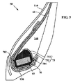
図5は、本発明の一実施形態としてのタイヤビードの変形例の概略半径方向断面図である。図3のタイヤ10のビードとは対照的に、被覆異形要素75は、保持補強材751と配合ゴムで作られていて、周方向補強材70を包囲したゴム充填剤752の両方を有している。保持補強材751は、硬質の配合ゴム(10パーセント弾性率が20℃において10MPaを超える)又はアラミド又はナイロンテキスタイル補強要素と配合ゴム、例えば、結合補強材の補強要素を埋め込んだ配合ゴムと同種の配合ゴムとから成る複合材で作られるのが良い。被覆異形要素75の周囲は、各半径方向断面で見て、半径方向内側の部分及び半径方向外側の部分を有し、これらの部分は、繋留構造体の軸方向最も内側及び軸方向最も外側の箇所702,704のところで互いに交わっている。この場合も又、カーカス補強材の端箇所65は、被覆補強要素75の周囲上又はその近くに配置されている。
FIG. 5 is a schematic radial cross-sectional view of a modified example of a tire bead as an embodiment of the present invention. In contrast to the bead of the
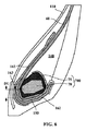
図6は、本発明の一実施形態としてのタイヤビードの別の変形例の概略半径方向断面図である。この場合、補剛補強材160は、2つの不連続の部分161,162で形成され、これら不連続部分は、重ね合わせ領域において互いにオーバーラップしている。この重ね合わせ領域は、繋留構造体の被覆異形要素の付近に配置され、このことは、補剛補強材160の軸方向外側ストランド162の軸方向内側端163と繋留構造体700の半径方向最も内側の箇所との間の距離DUが1.5DR(図3参照)未満であることを意味している。
FIG. 6 is a schematic radial cross-sectional view of another modified example of the tire bead as one embodiment of the present invention. In this case, the stiffening
任意の半径方向断面で見て、2つの不連続部分161,162相互間のインターフェイスの経路の曲線長さとして定義される重ね合わせ領域の長さLK(図7において両方向示す矢印によって示されている)は、繋留構造体700の軸方向最も遠くに離れた箇所702,704相互間の軸方向距離DA(図7参照)の少なくとも半分である。これら箇所702,704は、繋留構造体700に接線T1,T2を描くことにより得られ、これら接線は、タイヤの回転軸線に垂直である。この場合、LK=15mm、DA=19mmである。
The length LK of the overlap region defined by the curve length of the interface path between the two
この変形例は、これにより、2つの不連続分161,162の材料を異なるものにすることができるので有利であり、その手段として、互いに異なる種類の補強要素(例えば、一方の部分についてはテキスタイル補強要素、他方の部分については金属補強要素)を採用し若しくは互いに異なる被服材料を採用し、或いはこれら2つの組み合わせを採用する。また、この変形例は、製造性を向上させることができる。というのは、コンポーネント及び補強材の位置の正確さが高く、しかも製造ステーションのところで占有されるスペースが減少するからである。
This variant is advantageous because it makes it possible to make the materials of the two
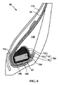
図8は、本発明の実施形態としてのタイヤビードの別の変形例の概略半径方向断面図である。この場合、結合補強材150は、ビード繋留構造体700の被覆異形要素75とカーカス補強材60との間に介在して設けられている。かくして、カーカス補強材60の端部65は、結合補強材150と補剛補強材160との間に位置決めされる。この構成により、各ビード内におけるカーカス補強材の良好な機械的健全性が保証されると共にこの補強材の補強要素がタイヤの使用中、周方向補強材70に接触しないようになる。
FIG. 8 is a schematic radial cross-sectional view of another modified example of a tire bead as an embodiment of the present invention. In this case, the
サイズ295/60R22.5の重車両タイヤでは、ビードの新規な幾何学的形状は、ビードの耐久性を実質的に向上させた。タイヤが大きな荷重(そのサイズに関する公称荷重よりも約50%高い荷重)を受けながら機械上で転動する耐久試験の際、国際公開第2008/107234(A1)号パンフレットのタイヤと比較して有効寿命が60%以上延びた。 In heavy vehicle tires of size 295 / 60R22.5, the new bead geometry substantially improved bead durability. Effective compared to the tire of the pamphlet of International Publication No. 2008/107234 (A1) in the durability test in which the tire rolls on the machine while receiving a large load (a load approximately 50% higher than the nominal load related to the size) Lifespan increased by 60% or more.
Claims (10)
トレッド(30)を載せたクラウン補強材(80,90)を含むクラウンを有し、
前記クラウンの半径方向内方の延長部としての2つのサイドウォール(40)を有し、
前記サイドウォールの半径方向内側に設けられていて、前記リムに係合するよう設計された2つのビード(50)を有し、各ビードは、繋留構造体(700)を有し、前記繋留構造体は、周方向補強材(70)を有し、前記繋留構造体は、任意の半径方向断面で見て、半径方向最も外側の箇所(701)、軸方向最も内側の箇所(702)及び軸方向最も外側の箇所(704)を有し、
周方向と80°以上の角度をなす方向に差し向けられた複数の補強要素(61)を含む半径方向カーカス補強材(60)を有し、前記カーカス補強材は、前記ビードの各々の中で、前記繋留構造体に繋留されており、前記カーカス補強材は、前記タイヤの内側から外側に軸方向に延びた状態で一部が前記繋留構造体に巻き付けられ、前記カーカス補強材の端箇所(65)は、前記繋留構造体上に又はこの近くで且つ前記繋留構造体の軸方向最も内側の箇所(702)と前記軸方向最も外側の箇所(704)との間で軸方向に配置され、
前記周方向と70°以上の角度をなす方向に差し向けられた複数の補強要素で形成された結合補強材(150)を有し、前記結合補強材は、前記繋留構造体の前記半径方向最も外側の箇所(701)に関して半径方向外側に位置した端箇所(155)と前記カーカス補強材の前記端箇所(65)との間で前記カーカス補強材と接触状態にある第1の部分(151)を有し、前記カーカス補強材の前記端箇所(65)を越える前記結合補強材の延長部として、前記繋留構造体の半径方向外側に位置した端箇所(157)まで前記繋留構造体(700)と接触状態にある第2の部分(152)が設けられ、前記結合補強材の前記端箇所(157)は、前記繋留構造体の前記軸方向最も内側の箇所(702)と前記軸方向最も外側の箇所(704)との間で軸方向に配置され、
前記結合補強材(150)を包囲した補剛補強材(160)を有し、前記補剛補強材は、軸方向内側部分(161)及び軸方向外側部分(162)を形成するよう前記繋留構造体(700)及び前記結合補強材の半径方向内側で延びており、前記軸方向内側部分は、前記カーカス補強材(60)に対して軸方向内側に位置し、前記軸方向外側部分は、前記カーカス補強材の軸方向外側に位置し、前記軸方向内側部分(161)は、前記軸方向内側部分(161)の前記端箇所(165)と前記結合補強材(150)の前記端箇所(155)との間で前記カーカス補強材と距離LCにわたり接触状態にあり、前記軸方向内側部分(161)の前記端箇所(165)は、前記結合補強材(150)の前記端箇所(155)の半径方向外側に配置され、前記補剛補強材は、前記周方向と50°以下の角度をなす平均方向に差し向けられた複数の補強要素で作られ、
前記補剛補強材(160)の前記軸方向外側の端箇所(166)は、前記繋留構造体(700)の前記周方向補強要素(70)の半径方向最も内側の箇所(73)から半径方向距離DRのところに配置され、前記半径方向距離DRは、前記繋留構造体(700)の前記周方向補強材(70)の前記半径方向最も内側の箇所(73)と前記半径方向最も外側の箇所(71)との間の前記半径方向距離DSの0.8倍以上であり且つ前記繋留構造体の前記周方向補強材(70)の前記半径方向最も内側の箇所(73)と前記半径方向最も外側の箇所(71)との間の前記半径方向距離DSの1.2倍以下である、タイヤ。 A heavy vehicle tire (10) adapted to be attached to a rim,
A crown including a crown reinforcement (80, 90) carrying a tread (30);
Having two sidewalls (40) as radially inward extensions of the crown;
There are two beads (50) provided radially inside the sidewall and designed to engage the rim, each bead having a tether structure (700), the tether structure The body has a circumferential reinforcement (70), and the anchoring structure is seen in any radial cross section, the radially outermost location (701), the axially innermost location (702) and the shaft. Having the outermost point (704) in the direction,
A radial carcass reinforcement (60) including a plurality of reinforcement elements (61) oriented in a direction that makes an angle of 80 ° or more with the circumferential direction, wherein the carcass reinforcement is in each of the beads The carcass reinforcing material is partly wound around the anchoring structure in a state of extending in the axial direction from the inside to the outside of the tire, and the end portion of the carcass reinforcing material ( 65) is axially disposed on or near the anchoring structure and between the axially innermost location (702) and the axially outermost location (704) of the anchoring structure,
A joint reinforcing material (150) formed of a plurality of reinforcing elements oriented in a direction that forms an angle of 70 ° or more with the circumferential direction, and the joint reinforcing material is the most in the radial direction of the anchoring structure. A first portion (151) in contact with the carcass reinforcement between the end location (155) located radially outward with respect to the outer location (701) and the end location (65) of the carcass reinforcement. The anchoring structure (700) as an extension of the joint reinforcement over the end location (65) of the carcass reinforcement up to an end location (157) located radially outward of the anchoring structure A second portion (152) that is in contact with the end portion (157) of the joint reinforcing material, the axially innermost portion (702) of the anchoring structure and the axially outermost portion. Part of (704) It is disposed axially between,
The anchoring structure includes a stiffening reinforcing material (160) surrounding the joint reinforcing material (150), wherein the stiffening reinforcing material forms an axially inner portion (161) and an axially outer portion (162). Extending radially inward of the body (700) and the coupling reinforcement, the axially inner portion is located axially inward with respect to the carcass reinforcement (60), and the axially outer portion is Located on the axially outer side of the carcass reinforcing material, the axially inner portion (161) includes the end portion (165) of the axially inner portion (161) and the end portion (155) of the coupling reinforcing material (150). ) In contact with the carcass reinforcing material over a distance LC, and the end portion (165) of the axially inner portion (161) is connected to the end portion (155) of the coupling reinforcing material (150). Arranged radially outward The stiffening reinforcement is made of a plurality of reinforcing elements directed to the average direction forming the circumferential direction than 50 ° angle,
The axially outer end portion (166) of the stiffening reinforcement (160) is radial from the radially innermost portion (73) of the circumferential reinforcing element (70) of the anchoring structure (700). The radial distance DR is arranged at the distance DR, and the radial innermost point (73) and the radially outermost point of the circumferential reinforcing member (70) of the anchoring structure (700). The radial distance DS between them and (71) is 0.8 times or more and the radially innermost portion (73) of the circumferential reinforcing member (70) of the anchoring structure and the radial direction most A tire which is 1.2 times or less of the radial distance DS between the outer part (71).
Applications Claiming Priority (5)
| Application Number | Priority Date | Filing Date | Title |
|---|---|---|---|
| FR0955330 | 2009-07-30 | ||
| FR0955330A FR2948604B1 (en) | 2009-07-30 | 2009-07-30 | PNEUMATIC VEHICLE FOR HEAVY WEIGHT HAVING REINFORCED BOURRELETS. |
| US25541009P | 2009-10-27 | 2009-10-27 | |
| US61/255,410 | 2009-10-27 | ||
| PCT/EP2010/060860 WO2011012605A1 (en) | 2009-07-30 | 2010-07-27 | Tyre for heavy goods vehicle having a reinforced bead |
Publications (1)
| Publication Number | Publication Date |
|---|---|
| JP2013500197A true JP2013500197A (en) | 2013-01-07 |
Family
ID=41511004
Family Applications (1)
| Application Number | Title | Priority Date | Filing Date |
|---|---|---|---|
| JP2012522144A Pending JP2013500197A (en) | 2009-07-30 | 2010-07-27 | Heavy vehicle tires with reinforced beads |
Country Status (9)
| Country | Link |
|---|---|
| US (1) | US8973636B2 (en) |
| EP (1) | EP2459397B1 (en) |
| JP (1) | JP2013500197A (en) |
| CN (1) | CN102481812B (en) |
| BR (1) | BR112012002165A8 (en) |
| FR (1) | FR2948604B1 (en) |
| IN (1) | IN2012DN00821A (en) |
| RU (1) | RU2517937C2 (en) |
| WO (1) | WO2011012605A1 (en) |
Cited By (1)
| Publication number | Priority date | Publication date | Assignee | Title |
|---|---|---|---|---|
| WO2020090983A1 (en) * | 2018-10-31 | 2020-05-07 | 株式会社ブリヂストン | Tire |
Families Citing this family (4)
| Publication number | Priority date | Publication date | Assignee | Title |
|---|---|---|---|---|
| DE102013226442A1 (en) * | 2013-12-18 | 2015-06-18 | Continental Reifen Deutschland Gmbh | Vehicle tires |
| DE102013226443A1 (en) * | 2013-12-18 | 2015-06-18 | Continental Reifen Deutschland Gmbh | Vehicle tires |
| CN104354536B (en) * | 2014-10-13 | 2017-06-16 | 王友善 | A kind of preparation method of full steel wire tubeless meridian tire |
| WO2019115917A1 (en) * | 2017-12-11 | 2019-06-20 | Compagnie Generale Des Etablissements Michelin | Pneumatic tyre for vehicle with reinforcing structure in the lower toric cavity |
Citations (7)
| Publication number | Priority date | Publication date | Assignee | Title |
|---|---|---|---|---|
| JP2001191759A (en) * | 2000-01-14 | 2001-07-17 | Bridgestone Corp | Pneumatic tire |
| JP2005112134A (en) * | 2003-10-07 | 2005-04-28 | Sumitomo Rubber Ind Ltd | Tire for heavy load |
| JP2005153731A (en) * | 2003-11-26 | 2005-06-16 | Sumitomo Rubber Ind Ltd | Pneumatic tire |
| JP2006044576A (en) * | 2004-08-06 | 2006-02-16 | Sumitomo Rubber Ind Ltd | Heavy load tire |
| JP2008531398A (en) * | 2005-03-07 | 2008-08-14 | ソシエテ ド テクノロジー ミシュラン | Tire bead structure |
| WO2008107234A1 (en) * | 2007-02-12 | 2008-09-12 | Societe De Technologie Michelin | Tyre bead structure |
| WO2009051260A1 (en) * | 2007-10-19 | 2009-04-23 | Bridgestone Corporation | Pneumatic tire |
Family Cites Families (5)
| Publication number | Priority date | Publication date | Assignee | Title |
|---|---|---|---|---|
| FR2781425B1 (en) * | 1998-07-23 | 2000-09-01 | Michelin Rech Tech | REINFORCED RADIAL TIRE SADDLE |
| US6802351B1 (en) | 1999-07-02 | 2004-10-12 | Bridgestone Corporation | Pneumatic tires |
| US6491079B2 (en) | 2000-01-14 | 2002-12-10 | Bridgestone Corporation | Pneumatic tire with turnup portion wrapped along outer peripheral face of bead core |
| US7165590B2 (en) | 2003-11-26 | 2007-01-23 | Sumitomo Rubber Industries, Ltd. | Heavy duty pneumatic radial tire with carcass ply winding-up portion |
| FR2873624B1 (en) | 2004-08-02 | 2006-09-22 | Michelin Soc Tech | PNEUMATIC BOURRELET |
-
2009
- 2009-07-30 FR FR0955330A patent/FR2948604B1/en not_active Expired - Fee Related
-
2010
- 2010-07-27 RU RU2012107067/11A patent/RU2517937C2/en not_active IP Right Cessation
- 2010-07-27 WO PCT/EP2010/060860 patent/WO2011012605A1/en active Application Filing
- 2010-07-27 US US13/387,954 patent/US8973636B2/en not_active Expired - Fee Related
- 2010-07-27 EP EP10737884.6A patent/EP2459397B1/en not_active Not-in-force
- 2010-07-27 BR BR112012002165A patent/BR112012002165A8/en not_active Application Discontinuation
- 2010-07-27 IN IN821DEN2012 patent/IN2012DN00821A/en unknown
- 2010-07-27 JP JP2012522144A patent/JP2013500197A/en active Pending
- 2010-07-27 CN CN201080040428.9A patent/CN102481812B/en not_active Expired - Fee Related
Patent Citations (8)
| Publication number | Priority date | Publication date | Assignee | Title |
|---|---|---|---|---|
| JP2001191759A (en) * | 2000-01-14 | 2001-07-17 | Bridgestone Corp | Pneumatic tire |
| JP2005112134A (en) * | 2003-10-07 | 2005-04-28 | Sumitomo Rubber Ind Ltd | Tire for heavy load |
| JP2005153731A (en) * | 2003-11-26 | 2005-06-16 | Sumitomo Rubber Ind Ltd | Pneumatic tire |
| JP2006044576A (en) * | 2004-08-06 | 2006-02-16 | Sumitomo Rubber Ind Ltd | Heavy load tire |
| JP2008531398A (en) * | 2005-03-07 | 2008-08-14 | ソシエテ ド テクノロジー ミシュラン | Tire bead structure |
| WO2008107234A1 (en) * | 2007-02-12 | 2008-09-12 | Societe De Technologie Michelin | Tyre bead structure |
| JP2010517865A (en) * | 2007-02-12 | 2010-05-27 | ソシエテ ド テクノロジー ミシュラン | Tire bead structure |
| WO2009051260A1 (en) * | 2007-10-19 | 2009-04-23 | Bridgestone Corporation | Pneumatic tire |
Cited By (1)
| Publication number | Priority date | Publication date | Assignee | Title |
|---|---|---|---|---|
| WO2020090983A1 (en) * | 2018-10-31 | 2020-05-07 | 株式会社ブリヂストン | Tire |
Also Published As
| Publication number | Publication date |
|---|---|
| BR112012002165A8 (en) | 2018-01-02 |
| EP2459397A1 (en) | 2012-06-06 |
| RU2012107067A (en) | 2013-09-10 |
| WO2011012605A1 (en) | 2011-02-03 |
| RU2517937C2 (en) | 2014-06-10 |
| US8973636B2 (en) | 2015-03-10 |
| US20120211140A1 (en) | 2012-08-23 |
| IN2012DN00821A (en) | 2015-06-26 |
| CN102481812A (en) | 2012-05-30 |
| CN102481812B (en) | 2016-03-16 |
| BR112012002165A2 (en) | 2016-05-31 |
| EP2459397B1 (en) | 2013-05-01 |
| FR2948604A1 (en) | 2011-02-04 |
| FR2948604B1 (en) | 2012-11-09 |
Similar Documents
| Publication | Publication Date | Title |
|---|---|---|
| JP6249518B2 (en) | Pneumatic tire | |
| JP5687063B2 (en) | Run-flat tires with additional sidewall reinforcement | |
| JP5098093B2 (en) | Tire bead structure | |
| JP6554957B2 (en) | Heavy duty pneumatic tire | |
| JP4491134B2 (en) | Reinforced tire beads for radial tires | |
| JP4648728B2 (en) | Heavy duty tire | |
| JP6790845B2 (en) | Pneumatic tires for heavy loads | |
| JP5612086B2 (en) | Heavy-duty vehicle tire beads | |
| JP6463226B2 (en) | Heavy duty tire | |
| JP4621068B2 (en) | Heavy duty tire | |
| JPWO2006003742A1 (en) | Pneumatic tire | |
| EP2439082A2 (en) | A tire with a metallic belt reinforcement | |
| JP2013500197A (en) | Heavy vehicle tires with reinforced beads | |
| JP4130530B2 (en) | Lock bead structure | |
| JP4473756B2 (en) | Heavy duty tire | |
| US20180037068A1 (en) | Tire having chafer structure for enhancing bead endurance | |
| JP2018079735A (en) | Pneumatic tire | |
| US8813804B2 (en) | Tire for heavy goods vehicle having a reinforced bead | |
| JP6384032B2 (en) | Pneumatic radial tire for construction vehicles | |
| JP5639648B2 (en) | Heavy vehicle tires with reinforced beads | |
| JP5438427B2 (en) | Racing cart tires | |
| JP4761866B2 (en) | Pneumatic tire | |
| JP6809839B2 (en) | Pneumatic tires | |
| JP5859821B2 (en) | Pneumatic radial tire | |
| JP5169489B2 (en) | Heavy duty pneumatic tire |
Legal Events
| Date | Code | Title | Description |
|---|---|---|---|
| A621 | Written request for application examination |
Free format text: JAPANESE INTERMEDIATE CODE: A621 Effective date: 20130620 |
|
| A977 | Report on retrieval |
Free format text: JAPANESE INTERMEDIATE CODE: A971007 Effective date: 20140219 |
|
| A131 | Notification of reasons for refusal |
Free format text: JAPANESE INTERMEDIATE CODE: A131 Effective date: 20140224 |
|
| A02 | Decision of refusal |
Free format text: JAPANESE INTERMEDIATE CODE: A02 Effective date: 20140818 |