JP2013258024A - Illumination control system - Google Patents
Illumination control system Download PDFInfo
- Publication number
- JP2013258024A JP2013258024A JP2012132888A JP2012132888A JP2013258024A JP 2013258024 A JP2013258024 A JP 2013258024A JP 2012132888 A JP2012132888 A JP 2012132888A JP 2012132888 A JP2012132888 A JP 2012132888A JP 2013258024 A JP2013258024 A JP 2013258024A
- Authority
- JP
- Japan
- Prior art keywords
- control
- wireless
- mode
- unit
- wireless receiver
- Prior art date
- Legal status (The legal status is an assumption and is not a legal conclusion. Google has not performed a legal analysis and makes no representation as to the accuracy of the status listed.)
- Granted
Links
Images


Classifications
-
- Y—GENERAL TAGGING OF NEW TECHNOLOGICAL DEVELOPMENTS; GENERAL TAGGING OF CROSS-SECTIONAL TECHNOLOGIES SPANNING OVER SEVERAL SECTIONS OF THE IPC; TECHNICAL SUBJECTS COVERED BY FORMER USPC CROSS-REFERENCE ART COLLECTIONS [XRACs] AND DIGESTS
- Y02—TECHNOLOGIES OR APPLICATIONS FOR MITIGATION OR ADAPTATION AGAINST CLIMATE CHANGE
- Y02B—CLIMATE CHANGE MITIGATION TECHNOLOGIES RELATED TO BUILDINGS, e.g. HOUSING, HOUSE APPLIANCES OR RELATED END-USER APPLICATIONS
- Y02B20/00—Energy efficient lighting technologies, e.g. halogen lamps or gas discharge lamps
- Y02B20/40—Control techniques providing energy savings, e.g. smart controller or presence detection
Abstract
Description
本発明は、熱線センサ及び照度センサを備える無線発信器、及び無線発信器と無線接続された無線受信器を用いて照明器具を制御する照明制御システムに関する。 The present invention relates to a wireless transmitter including a heat ray sensor and an illuminance sensor, and an illumination control system that controls a lighting fixture using a wireless receiver wirelessly connected to the wireless transmitter.
従来より、住宅やビルディング内において、明るさセンサや人感センサといったセンサ類と連携して複数の照明器具のON/OFFや調光状態を個別に、又は一括して制御する照明制御システムが導入されている。この照明制御システムでは、外光の明るさや人の存在に応じて照明器具のON/OFFを適切に制御できるため省エネルギー化を図ることができる。 Conventionally, lighting control systems that control the ON / OFF and dimming status of multiple lighting fixtures individually or collectively in cooperation with sensors such as brightness sensors and human sensors in homes and buildings have been introduced. Has been. In this illumination control system, the ON / OFF of the lighting fixture can be appropriately controlled according to the brightness of external light and the presence of a person, so that energy saving can be achieved.
例えば、図8に示す照明制御システムは、熱線センサ及び照度センサを有する無線発信器101と、無線発信器101と無線通信で接続された無線受信器102と、伝送ユニット103と、リレー制御用端末器104とを備える。伝送ユニット103は、2線式の信号線Lsを介して無線受信器102及びリレー制御用端末器104と接続され、無線受信器102を介して無線発信器101において発生した照明器具105の制御情報を受信して動作制御を行う。
For example, the illumination control system shown in FIG. 8 includes a
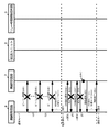
次に、本図に示す照明制御システムの動作に関して説明する。無線ネットワークを利用する照明制御システムでは、無線発信器101から定期的(例えば5分毎)にビーコンと呼ばれる報知情報が無線受信器102に送信されて無線ネットワークの時間的な同期が実行される(S110)。無線受信器102は、このビーコン同期によって無線発信器101とのデータ送受信タイミングを確認できる。無線発信器101は、照度センサが検出した周囲照度値が設定照度値以下の状態で、熱線センサからの入力が閾値を超えて人検知された場合、照明器具のON制御要求を自らのタイミングで無線受信器102に送信できる(S111)。
Next, the operation of the illumination control system shown in this figure will be described. In the lighting control system using a wireless network, notification information called a beacon is periodically transmitted from the wireless transmitter 101 (for example, every 5 minutes) to the
次に、ON制御要求を受信した無線受信器102は、制御データであるON通知を伝送ユニット103に送信する(S112)。そして、伝送ユニット103は、制御対象となる照明器具105と対応するリレー制御用端末器104に対して、照明器具105のアドレス情報と、ON制御状態とを含む制御指令信号を送信する(S113)。そして、リレー制御用端末器104が照明器具105をON制御し、照明器具105のON制御が完了したことを示すACKを伝送ユニット103に通知する(S114)。また、伝送ユニット103は、無線受信器102に照明器具105のON制御が完了したことを通知し(S115)、無線受信器102から無線発信器101にACKが通知される(S116)。このACKにより、無線発信器101はON制御要求の成立を判断できる。
Next, the
また、無線発信器101は、ON制御要求を送信してから動作保持時間が満了すると照明器具105をOFF制御するためのOFF制御要求を無線受信器102に送信する(S117)。OFF制御要求を受信した無線受信器102は、制御データであるOFF通知を伝送ユニット103に送信する(S118)。そして、伝送ユニット103は、制御対象となる照明器具105と対応するリレー制御用端末器104に対して、照明器具105のアドレス情報と、OFF制御状態とを含む制御指令信号を送信する(S119)。次に、リレー制御用端末器104が照明器具105をOFF制御し、このOFF制御が完了したことを示すACKを伝送ユニット103に通知する(S120)。また、伝送ユニット103は、受信器102に照明器具105のOFF制御が完了したことを通知し(S121)、無線受信器102から無線発信器101にACKが通知される(S122)。
In addition, when the operation holding time expires after transmitting the ON control request, the
ところで、2線式リモコンで照明器具を制御する遠隔監視制御システムとして、検知エリア内の人の存否に応じた所望の制御が簡単な構成で行うことができる遠隔監視制御システムが開示されている(例えば、特許文献1参照)。 By the way, as a remote monitoring control system that controls a lighting fixture with a two-wire remote controller, a remote monitoring control system that can perform desired control according to the presence or absence of a person in a detection area with a simple configuration is disclosed ( For example, see Patent Document 1).
しかしながら、上記従来の照明制御システムは、計画停電や、無線受信器102と無線発信器101の施工中もしくは施工後の引渡しまでの間のメンテナンス作業のために停電される可能性がある。この場合、無線受信器102は通電されずに電源は切られた状態で放置され、無線発信器101はリチウムイオン電池などの電池を入れたまま放置される。この結果、無線発信器101の周辺に人がいた場合、図9に示すように、無線発信器101は、無線受信器102に対してリトライも含めたON制御要求(S111)の送信を継続的に繰り返して行い、電池が通常よりも早期(約1日などで)に切れてしまう。
However, the conventional lighting control system may be interrupted due to a planned power outage or maintenance work during the construction of the
すなわち、現状において無線発信器101は、無線受信器102の不在や電源切りの状態を認識できず、この場合、上述のように消費電力を要する送信動作(S111)を繰り返し、電池寿命を縮めてしまうという問題がある。
That is, at present, the
本発明は、上記課題に鑑みてなされたものであり、無線受信器との間で無線通信が取れなくなった場合においても、無線発信器が送信動作を繰り返して電池寿命が短くなることを防止した照明制御システムを提供することを目的とする。 The present invention has been made in view of the above problems, and even when wireless communication with a wireless receiver is not possible, the wireless transmitter has prevented the battery life from being shortened by repeating the transmission operation. An object is to provide a lighting control system.
上記目的を達成するために本発明は、検知エリア内の照度を検知する照度センサ及び前記検知エリア内の人体から放射される熱線を検知する熱線センサによる各検知結果に基づいて照明負荷の動作制御をする無線発信器と、前記無線発信器と無線通信される無線受信器と、を備える照明制御システムにおいて、前記無線発信器は、前記照度センサで検出される周囲照度値が、照明負荷の制御のため予め設定された設定照度値未満であり、且つ前記熱線センサで人検知された場合、照明負荷をON制御するためのON制御要求を前記無線受信器に送信すると共に、前記ON制御要求に対するACKを前記無線発信器から受信できない場合、所定の送信間隔で前記ON制御要求を繰り返して送信するよう制御する制御手段と、定期的に報知情報であるビーコンを送信することで前記無線受信器と時間的な同期をとる同期手段と、前記同期手段におけるビーコン同期の連続した不成立の回数をカウントするカウント手段と、前記カウント手段における回数が所定値以上になると、前記ON制御要求の送信間隔を、前記所定の送信間隔より長くした低周期モードに変更するモード変更手段と、を備えることを特徴とする。 In order to achieve the above object, the present invention provides an illumination load operation control based on detection results of an illuminance sensor that detects illuminance in a detection area and a heat ray sensor that detects heat rays emitted from a human body in the detection area. And a wireless receiver wirelessly communicating with the wireless transmitter, wherein the wireless transmitter has an ambient illuminance value detected by the illuminance sensor to control a lighting load. Therefore, when the illumination intensity is less than a preset illuminance value and a person is detected by the heat ray sensor, an ON control request for ON control of an illumination load is transmitted to the wireless receiver, and the ON control request is When ACK cannot be received from the wireless transmitter, control means for controlling to repeatedly transmit the ON control request at a predetermined transmission interval, and periodically broadcast information Synchronization means for synchronizing in time with the wireless receiver by transmitting a beacon, a counting means for counting the number of consecutive failures of beacon synchronization in the synchronization means, and a count in the counting means equal to or greater than a predetermined value Then, mode change means for changing the transmission interval of the ON control request to a low cycle mode longer than the predetermined transmission interval is provided.
この照明制御システムにおいて、前記所定の送信間隔でON制御要求を送信する期間を通常モードとし、前記モード変更手段は、前記低周期モードにおいて送信した前記ON制御要求に対するACKを前記無線受信器から受信した場合、又は前記無線受信器から復帰通知を受けた場合、前記低周期モードから前記通常モードに復帰することが好ましい。 In this lighting control system, a period during which the ON control request is transmitted at the predetermined transmission interval is set to a normal mode, and the mode changing unit receives an ACK for the ON control request transmitted in the low cycle mode from the wireless receiver. Or when receiving a return notification from the wireless receiver, it is preferable to return from the low cycle mode to the normal mode.
この照明制御システムにおいて、前記モード変更手段は、さらに前記無線受信器と同期がとれた後に前記低周期モードから前記通常モードに復帰することが好ましい。 In this illumination control system, it is preferable that the mode change unit returns from the low cycle mode to the normal mode after further synchronization with the wireless receiver.
本発明に係る照明制御システムによれば、無線発信器は、ビーコン同期の連続した不成立回数をカウントし、この回数が所定値以上となると制御情報の送信間隔を長くする低周期モードに移行する。このことで、無線発信器は、無線受信器との間で無線通信が取れなくなった場合でも、短い送信間隔での発報動作を繰り返すことなく、電池寿命を長く保つことができる。 According to the lighting control system of the present invention, the wireless transmitter counts the number of consecutive failure of beacon synchronization, and shifts to a low-cycle mode in which the control information transmission interval is lengthened when this number exceeds a predetermined value. As a result, the wireless transmitter can keep the battery life long without repeating the reporting operation at a short transmission interval even when wireless communication with the wireless receiver becomes impossible.
本発明の実施の形態に係る照明制御システムについて図面を参照して説明する。 An illumination control system according to an embodiment of the present invention will be described with reference to the drawings.
(実施の形態1)
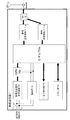
図1は、本実施の形態1に係る照明制御システム1の構成を示す。この照明制御システム1は、伝送ユニット2と、リレー制御用端末器3と、リモコンリレー4と、リモコントランス5と、リモコンスイッチ6と、無線受信器7と、無線発信器8と、照明器具9とを備えている。
(Embodiment 1)
FIG. 1 shows a configuration of a
リレー制御用端末器3、リモコンスイッチ6、及び無線受信器7は、2線式の信号線を介して伝送ユニット2と相互に接続されており、伝送ユニット2との情報のやり取りは、信号線に多重伝送方式で伝送される伝送信号を通して行われる。この照明制御システム1では、無線受信器7と無線発信器8との間で無線通信を行い、照明器具9のオン/オフ状態や室内の照度を自動制御する。
The
伝送ユニット2は、リモコンスイッチ6や無線受信器7からの伝送信号に基づいて、伝送信号に含まれるアドレス情報から制御対象となる照明器具9を特定すると共に、照明器具9に対する制御状態を特定する。そして、伝送ユニット2は、制御対象となる照明器具9と対応するリレー制御用端末器3に対して、照明器具9のアドレス情報と、その制御状態(ON、OFFや調光レベルなど)とを制御指令信号として送信する。
Based on the transmission signal from the remote control switch 6 or the
照明制御システム1内に存在する照明器具9は、負荷アドレスによって一意に特定することができる。具体的には、リレー制御用端末器3には、負荷チャネル(Ch)と呼ばれる固有の識別子が割り当てられており、リレー制御用端末器3に接続するリモコンリレー4には、負荷ナンバー(Nm)を呼ばれる固有の識別子が割り当てられている。負荷チャネル(Ch)と、負荷ナンバー(Nm)とを組み合わせることにより、負荷アドレス(Ch−Nm)が構成される。
The lighting fixture 9 existing in the
リレー制御用端末器3は、リレーの制御状態に応じて照明器具9の状態を制御する負荷制御端末器としての機能を担っている。リレー制御用端末器3は、伝送ユニット2からの伝送信号に基づいて、自己に接続するリモコンリレー4のうち、制御対象となる照明器具9に対応するリモコンリレー4に対して制御信号を送ることにより、リモコンリレー4の状態を制御する。リモコンリレー4の個々のリレーは、リレー制御用端末器3に制御されて、ブレーカ電源(AC100又は200V)10などからの商用交流をオン/オフすることで、照明器具9をオン状態またはオフ状態にする。
The
リモコントランス5は、リレー制御用端末器3、及びリモコンリレー4に駆動用の電力を供給する。
The
リモコンスイッチ6は、照明器具9を制御するための制御指令を出力するための入力端末器としての機能を担っている。具体的には、リモコンスイッチ6は、例えば室内などの任意の壁面に設置されており、照明器具9を利用するユーザによってプッシュ操作が可能な端末器である。リモコンスイッチ6は、操作スイッチのいずれかが操作されるのに応じて、その操作スイッチに関連付けられているアドレス情報と、操作スイッチの操作状態とを制御指令として伝送ユニット2に送信する。
The remote control switch 6 has a function as an input terminal for outputting a control command for controlling the lighting fixture 9. Specifically, the remote control switch 6 is a terminal device that is installed on an arbitrary wall surface such as a room, for example, and can be pushed by a user using the lighting fixture 9. In response to any of the operation switches being operated, the remote control switch 6 transmits the address information associated with the operation switch and the operation state of the operation switch to the
無線受信器7は、天井面に埋め込まれ、無線発信器8とワイヤレスで制御情報の送受信を行うと共に、2線式の信号線と接続して伝送ユニット2と制御データの送受信を行う。この無線受信器7には、例えば電波式ワイヤレスアドレス設定器を用いて、アドレスやエリアナンバーが設定される。
The
無線発信器8は、レイアウトフリーに壁面に設置され、検知エリア周辺の照度を検知する照度センサ、及び検知エリア内の人体から放射される熱線を検知する熱線センサを備える。また、無線発信器8の背面側には、ユーザ操作されるアドレス設定選択つまみ、動作保持時間設定用つまみなどが設けられている。
The
熱線センサは、人体から放射される熱線を検出して検知エリア内の人の存否に応じて出力する人体検出信号を監視する。無線発信器8は、検知エリア内の人の動きが検出されたときに照明器具9を自動でのON/OFF制御や自動調光させるためのアドレス情報や制御情報を無線受信器7に送信可能とする。また、無線発信器8は、熱線センサによって検知エリア内で人検出されてから所定の動作保持時間経過後に照明器具9を消灯するためのOFF制御要求を無線受信器7に送信する。
The heat ray sensor detects a heat ray emitted from a human body and monitors a human body detection signal output according to the presence or absence of a person in the detection area. The
照度センサは、検知エリアの明るさを検知(照度検知範囲5〜1000ルクス等)する。無線発信器8は、照度センサにより検知された照度に基づいて照明器具9を制御するための制御情報を無線受信器7に送信可能とする。この照度センサを用いた照明制御により、日没後は点灯するなど外光にあわせて平均照度を一定に保って調光でき、照明環境の快適性を保ちながら省エネを図ることができる。また、無線発信器8が熱線センサに加えて照度センサをも備えることで、暗くなり且つ人がいる時だけの点灯制御などが可能となる。
The illuminance sensor detects the brightness of the detection area (illuminance detection range of 5 to 1000 lux, etc.). The
無線発信器8には、例えば電波式ワイヤレスアドレス設定器を用いて、制御対象となる照明器具9のアドレス情報として、個別アドレス、パターンアドレスやグループアドレスなどが設定される。なお、個別アドレスは、個別制御の対象となる照明器具9を特定するための情報であり、負荷アドレス(個別「0−1」など)に該当する。グループアドレスは、複数の照明器具9を同一の制御状態へと一括的に制御するためグループ制御の対象となるグループを特定するための情報であり、予め設定された個々のグループに付与された番号(「G−1」など)がこれに該当する。パターンアドレスは、複数の照明器具9を、それぞれの照明器具9に予め定められた所定の制御状態へと一括的に制御するパターンを特定するための情報であり、予め設定された個々のパターンに付与された番号(「P−1」など)である。
An individual address, a pattern address, a group address, and the like are set in the
次に、本照明制御システム1に備わる無線発信器8の機能構成に関して図2を参照して説明する。無線発信器8は、CPU(制御手段)80、電源部81、ブザー82、サブクロック部83、熱線検知部84、LED表示部85、アドレス切替部86、無線送受信部87、照度測定部88、明るさ設定部89、動作保持時間設定部90、及びアドレス登録設定部91を備える。
Next, the functional configuration of the
CPU80は、さらに、ビーコン同期部80a、カウント部80b、モード変更部80c、タイマ部80dを備える。ビーコン同期部80aは、定期的(例えば5分毎)に報知情報であるビーコンを無線受信器7に送信して送信タイミングなどに関する時間的な同期(以下ビーコン同期という)をとるように制御する。なお、無線受信器7は、ビーコンに含まれる時間データに基づいて無線発信器8とのデータ送受信タイミングを確認する。
The CPU 80 further includes a beacon synchronization unit 80a, a
カウント部80bは、後述する通常モードにおいて無線発信器8が実行したビーコン同期の連続した不成立の回数をカウントする。モード変更部80cは、カウント部80bにおけるカウント数が所定回数(例えば3回)を超えた場合に通常モードから後述する低周期モードに変更する。また、モード変更部80cは、低周期モードにおいて無線受信器7からACKを受信した場合などにおいて通常モードに復帰する。タイマ部80dは、クロックを数えることで一定時間の経過を知るタイマ機能を有し、操作入力部93で入力された無線発信器8の動作保持時間の検出時にCUP80に対して割り込みを発生させる。
The
電源部81は、特定小電力無線に対応し、専用のリチウムイオン二次電池から内部の電源を供給する。ブザー82は、確認音や警告音を発音し、サブクロック部83は、水晶振動子によりCPU80の動作周波数を発生させる。 The power supply unit 81 corresponds to the specific low-power radio and supplies internal power from a dedicated lithium ion secondary battery. The buzzer 82 generates a confirmation sound and a warning sound, and the sub clock unit 83 generates an operating frequency of the CPU 80 by a crystal resonator.
熱線検知部84は、熱線の変化を検知する焦電素子のような熱線センサを具備し、熱線センサの出力を増幅してCPU80に出力する。CPU80は、熱線検知部84の出力と、記憶された所定の閾値との高低を比較することによって、検知エリア内の人の存否を判定している。また、CPU80は、例えば、熱線検知部84の焦電素子から所定間隔(3秒に1回など)で入力される検出信号の処理を所定期間において停止することでON制御要求の送信間隔を2分などに制御する。 The heat ray detector 84 includes a heat ray sensor such as a pyroelectric element that detects changes in the heat ray, amplifies the output of the heat ray sensor, and outputs the amplified output to the CPU 80. The CPU 80 determines the presence / absence of a person in the detection area by comparing the output of the heat ray detection unit 84 with the stored threshold value. Further, the CPU 80, for example, sets the transmission interval of the ON control request to 2 by stopping the processing of the detection signal input at a predetermined interval (such as once every 3 seconds) from the pyroelectric element of the heat ray detection unit 84 for a predetermined period. Control minutes and so on.
LED表示部85は、熱線センサにおいて人を検知した際やアドレス設定時、電源不足時などにおいて点滅や発光する。なお、操作入力部93によってユーザ入力された設定項目(例えば設定照度値、動作保持時間やアドレスデータ)の値は保持される。また、無線発信器8は、後述するように、無線発信器8の現在の送信モードが通常モードか低周期モードかを保持する。無線送受信部87は、専用のASICがアンテナに接続されて構成され、無線受信器7との間で制御情報の送受信を実現する。
The LED display unit 85 blinks or emits light when a person is detected by the heat ray sensor, when an address is set, or when a power supply is insufficient. Note that the values of the setting items (for example, the set illuminance value, the operation holding time, and the address data) input by the operation input unit 93 are held. Further, as will be described later, the
照度測定部88は、周囲の明るさを検出するCdS、フォトダイオード、フォトトランジスタのような照度センサを有し、照度センサの出力を増幅してCPU80に出力する。CPU80では、照度測定部88の出力と、保持された所定の明るさレベル(設定レベル)との明暗を比較する。 The illuminance measurement unit 88 includes an illuminance sensor such as CdS, a photodiode, or a phototransistor that detects ambient brightness, amplifies the output of the illuminance sensor, and outputs the amplified output to the CPU 80. The CPU 80 compares the output of the illuminance measuring unit 88 with the brightness of the held predetermined brightness level (setting level).
無線発信器8の背面に設けられたツマミ部である操作入力部93には、明るさ設定部89、動作保持時間設定部90、及びアドレス登録設定部91が備えられる。明るさ設定部89は、照明器具9の制御のための照度設定値を変更するための切替スイッチである。動作保持時間設定部90は、照明器具9の点灯を保持する時間を変更するための切替スイッチであり、30秒、3分、10分などから動作保持時間を選択する。アドレス登録設定部91は、別体の電波式アドレス設定器とデータを送受信して電波信号を受信する。アドレス切替部86は、番号1〜16などの内からアドレスを選択するツマミ部である。
The operation input unit 93 that is a knob unit provided on the back surface of the
次に、本照明制御システム1に備わる無線受信器7の機能構成に関して図3を参照して説明する。無線受信器7は、CPU(処理手段)70a,70b、無線送受信部71a,71b、スイッチ72、多重伝送信号送受信部73、電源部74、LED表示部75、及びメモリ部76を備える。
Next, the functional configuration of the
無線送受信部71a,71bは、専用のASICがアンテナに接続されて構成され、複数の無線発信器8との経路切り替えなどを行うスイッチ72を介して無線発信器8との間で制御情報の送受信を実現する。無線送受信部71a、71bは、無線発信器8から制御信号を受信すると、CPU70a,70bに検知信号を出力する。
The wireless transmission / reception units 71a and 71b are configured by connecting a dedicated ASIC to an antenna, and transmit / receive control information to / from the
伝送通信部たる多重伝送信号送受信部73は、一対の端子T1,T1に接続された信号線Lsを介して、伝送ユニット2との間で多重伝送方式により伝送信号の送受信を行う。また、多重伝送信号送受信部73は、信号線Lsを介して入力された伝送信号を信号変換してCPU70a,70bに出力し、CPU70a,70bから出力された信号を伝送信号に変換して信号線Lsに送出する。
A multiplex transmission signal transmission / reception unit 73 as a transmission communication unit transmits / receives transmission signals to / from the
電源部74は、信号線Lsを介して入力される伝送信号を全波整流器で全波整流し、さらに定電圧部で定電圧化することによって、内部の電源を得ている。 The power supply unit 74 obtains an internal power supply by full-wave rectifying a transmission signal input via the signal line Ls by a full-wave rectifier and further converting the transmission signal to a constant voltage by a constant voltage unit.
CPU70a,70bでは、多重伝送信号送受信部73を介して受信した伝送信号に含まれるアドレスデータがメモリ部76に格納されたアドレスデータに一致すると、伝送信号の制御データを受け取り、制御データに応じた動作をする。
In the
LED表示部75は、アドレス設定時などにおいて点滅や発光する。メモリ部76は、不揮発性メモリであり、設定項目(例えばエリアナンバーやアドレス)の値や無線受信器7の現在状態を記憶する。
The LED display unit 75 blinks or emits light when an address is set. The memory unit 76 is a non-volatile memory and stores values of setting items (for example, area numbers and addresses) and the current state of the
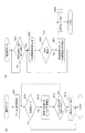
次に、本照明制御システム1の動作手順に関して図4を参照して説明する。最初に、無線発信器8のビーコン同期部80aは、ビーコン同期のために定期的(例えば5分毎)にビーコンを無線受信器7に送信してビーコン同期を行う(S10)。無線発信器8は、ビーコン同期に対するACKを受信できないなど、ビーコン同期が完了しない場合、5分後に再度、無線受信器7との間でビーコン同期を行う。このビーコン同期は、例えば、周期を5分毎に最大3回繰り返して行われる。
Next, the operation procedure of the
その後、無線発信器8のモード変更部80cは、カウント部80bにおいてカウントされたビーコン同期の連続した不成立が3回以上となる場合に低周期モードに移行する。すなわち、モード変更部80cは、3回目のビーコン同期の直後の6秒のビーコン受信モード(S11)においても同期完了できない場合、通常モードから低周期モードに移行する。
Thereafter, the
ここで、無線発信器8において管理している送信モードに関して図5を参照して説明する。テーブル30に示すように、通常モードにおいて、無線発信器8は、人検知した場合、送信間隔を最大3秒に1回(リトライ最大14回)として無線受信器7にON制御要求を送信する。低周期モードにおいて、無線発信器8は、人検知した場合、送信間隔を最大N分(例えば2分)に1回(リトライ最大14回)として無線受信器7に対してON制御要求を送信する。
Here, the transmission mode managed in the
そして、無線発信器8は、低周期モードにおいて、設定照度値が照度センサにおいて実際に検出した周囲照度値以上であり、且つ熱線センサからの入力が閾値を超えて人検知した場合、ON制御要求を無線受信器7に送信する(S12)。また、無線発信器8は、このON制御要求に対するACKを無線受信器7から受信しない場合(S13)、ON制御要求を再送(リトライ)する。このON制御要求の再送は、例えば、送信間隔を最大2分として最大14回繰り返して行われる。
And in the low cycle mode, when the set illuminance value is equal to or higher than the ambient illuminance value actually detected by the illuminance sensor and the input from the heat ray sensor exceeds the threshold value, the
そして、電源復帰など無線受信器7が無線発信器8と無線通信可能な状態に復帰すると(S14)、無線発信器8からのON制御要求(S15)に対して、無線受信器7は、制御データとしてON通知を伝送ユニット2に送信する(S16)。次に、伝送ユニット2は、制御対象となる照明器具9と対応するリレー制御用端末器3に対して、照明器具9のアドレス情報と、ON制御状態とを制御指令信号として送信する(S17)。そして、リレー制御用端末器3が照明器具9をON制御し、ON制御を完了したことを示すACKを伝送ユニット2に返信し(S18)、また、伝送ユニット2から無線受信器7に照明器具9のON制御が完了したことが通知される(S19)。
When the
そして、無線発信器8は、ON制御要求に対するACKを受信し(S20)、無線受信器7の復帰を判断して、例えば6秒間のビーコン受信モード(S21)中において、無線受信器7と無線発信器8とが同期完了(S22)した後、通常モードに復帰する。
Then, the
次に、無線発信器8の各送信モードにおける動作手順に関して図6を参照して説明する。図6(a)は無線発信器8の通常モードにおける動作手順を示す。最初に、無線発信器8のビーコン同期部80aは、無線受信器7との間で定期的なビーコン同期を実行する(S41)。そして、無線発信器8は、ビーコン同期を完了した場合には(S42でYes)、無線受信器7との間でデータの送受信が行える。すなわち、その後において、CPU80は、設定照度値が周囲照度値以上であり、且つ熱線センサからの入力が閾値を超えて人検知されたか否かを確認する。そして、人検知された場合には、CPU80は、ON制御要求を、無線送受信部87を介して無線受信器7に送信するように制御する。また、CPU80は、当該ON制御要求に対するACKを無線受信器7から受信できない場合には、送信間隔を最大3秒に1回(リトライ最大14回)として無線受信器7にON制御要求を再送する。
Next, the operation procedure in each transmission mode of the
一方、ビーコン同期に対するACKを受信できないなどビーコン同期が完了しない場合(S42でNo)、ビーコン同期部80aは、無線受信器7との間で5分後に再度のビーコン同期を実行する(S43)。そして、カウント部80bは、再度のビーコン同期も含めた連続したビーコン同期の不成立の回数を計数する。モード変更部80cは、カウント部80bにおいてカウントされるビーコン同期の連続した不成立の回数が所定回数(例えば3回)以上となったかを判定し(S44)、3回以上となる場合には(S44でYes)、低周期モードに移行する(S45)。
On the other hand, when the beacon synchronization is not completed (No in S42), for example, the ACK for the beacon synchronization cannot be received (No in S42), the beacon synchronization unit 80a executes the beacon synchronization again after 5 minutes with the wireless receiver 7 (S43). Then, the
次に、無線発信器8の低周期モードにおける動作手順に関して図6(b)を参照して説明する。最初に、CPU80は、設定照度値が周囲照度値以上となり、且つ熱線センサにおいて人検知されたか否かを確認する(S51)。そして、条件を満たす場合には(S51でYes)、CPU80は、ON制御要求を、無線送受信部87を介して無線受信器7に送信するように制御する(S52)。
Next, the operation procedure in the low cycle mode of the
次に、CPU80は、無線受信器7からのACKを受信したか否かを確認し(S53)、受信できない場合には(S53でNo)、所定の送信間隔(例えば2分)でON制御要求の再送を繰り返す(S54)。そして、モード変更部80cは、無線受信器7からのACKを受信できた場合には(S53でYes)、無線受信器7の電源が回復したとして通常モードに復帰する(S55)。
Next, the CPU 80 confirms whether or not an ACK from the
以上の説明のように、無線発信器8は、無線受信器7に対してビーコン同期を実行したにも関わらず、ビーコン同期が連続して所定回数(3回など)以上において成立しなかった場合、低周期モードに移行する。また、低周期モードから通常モードへの復帰のトリガを、低周期モードにおいて無線発信器8が無線受信器7からACKを受信できたこととする。
As described above, when the
この結果、計画停電やメンテナンス作業中など、無線受信器7が電源切状態で無線通信できず、且つ電池動作する無線発信器8の周囲に人が居る場合に、無線発信器8から無線受信器7への消費電力を要するON制御要求の発報頻度を減らすことができる。このため、無線発信器8の電池寿命が短くなることを確実に防止できる。また、無線発信器8は、送信モード変更のトリガを、低周期モードにおいて無線受信器7からACKを受信できた場合とするため、無線受信器7の通電後、通常モードに自動復帰できる。
As a result, when the
(実施の形態2)
以下、本発明に係る照明制御システムの実施の形態2に関して図7を参照して説明する。上記実施の形態1に係る照明制御システム1と同様の構成には同符号を付し、その詳細な説明は省略する。
(Embodiment 2)
Hereinafter,
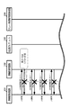
本実施の形態2に係る照明制御システム1の動作手順に関して図7を参照して説明する。なお、S10〜S14までの動作手順は上記実施の形態1の図4と同様であるため、その説明を省略する。本実施の形態2では、S14で無線受信器7が電源復帰すると、無線受信器7から無線発信器8に対して復帰通知がなされる(S23)。そして、無線発信器8は、例えば6秒間のビーコン受信モード(S24)中において、無線受信器7と無線発信器8とが同期完了(S25)した後に通常モードに復帰する。
The operation procedure of the
従って、本実施の形態2に係る照明制御システム1では、上記実施の形態1の効果に加えて、無線発信器8は、送信モード変更のトリガを低周期モードにおいて無線受信器7から復帰通知を受けた場合とでき、無線受信器7の通電後、通常モードに自動復帰できる。
Therefore, in the
なお、本発明は、上記各実施の形態の構成に限られず、発明の趣旨を変更しない範囲で種々の変形が可能である。例えば、無線発信器は1つに限定されるものではなく2つ以上でも同様の制御を実現できる。また、通常モードでのビーコン同期の連続した不成立の回数3回、通常モードでのON制御要求の送信間隔3秒や低周期モードでのON制御要求の送信間隔2分はあくまで例示であり、その他の数値であってもよい。 The present invention is not limited to the configuration of each of the embodiments described above, and various modifications can be made without departing from the spirit of the invention. For example, the number of wireless transmitters is not limited to one, and the same control can be realized with two or more wireless transmitters. In addition, the number of consecutive failures of beacon synchronization in the normal mode is 3 times, the transmission interval of the ON control request in the normal mode is 3 seconds, and the transmission interval of the ON control request in the low cycle mode is 2 minutes to the last. The numerical value of may be sufficient.
1 照明制御システム
2 伝送ユニット
3 リレー制御用端末器
4 リモコンリレー
5 リモコントランス
6 リモコンスイッチ
7 無線受信器
70 CPU
71a,71b 無線送受信部
76 メモリ部
8 無線発信器
80 CPU(制御手段)
80a ビーコン同期部(同期手段)
80b カウント部(カウント手段)
80c モード変更部(モード変更手段)
80d タイマ部
87 無線送受信部
9 照明器具
DESCRIPTION OF
71a, 71b Wireless transmission / reception unit 76
80a Beacon synchronization unit (synchronization means)
80b Count unit (counting means)
80c Mode change unit (mode change means)
80d Timer 87 Wireless transmitter / receiver 9 Lighting equipment
Claims (3)
前記無線発信器は、
前記照度センサで検出される周囲照度値が、照明負荷の制御のため予め設定された設定照度値未満であり、且つ前記熱線センサで人検知された場合、照明負荷をON制御するためのON制御要求を前記無線受信器に送信すると共に、前記ON制御要求に対するACKを前記無線発信器から受信できない場合、所定の送信間隔で前記ON制御要求を繰り返して送信するよう制御する制御手段と、
定期的に報知情報であるビーコンを送信することで前記無線受信器と時間的な同期をとる同期手段と、
前記同期手段におけるビーコン同期の連続した不成立の回数をカウントするカウント手段と、
前記カウント手段における回数が所定値以上になると、前記ON制御要求の送信間隔を、前記所定の送信間隔より長くした低周期モードに変更するモード変更手段と、を備える、ことを特徴とする照明制御システム。 An illuminance sensor for detecting illuminance in a detection area, a radio transmitter for controlling the operation of an illumination load based on each detection result by a heat ray sensor for detecting a heat ray emitted from a human body in the detection area, and the radio transmitter A lighting control system comprising:
The wireless transmitter is
ON control for ON control of the illumination load when the ambient illuminance value detected by the illuminance sensor is less than a preset illuminance value set in advance for controlling the illumination load and a person is detected by the heat ray sensor Control means for transmitting a request to the wireless receiver and controlling to repeatedly transmit the ON control request at a predetermined transmission interval when an ACK for the ON control request cannot be received from the wireless transmitter;
Synchronizing means that periodically synchronizes the wireless receiver by transmitting a beacon that is broadcast information periodically,
Counting means for counting the number of consecutive failure of beacon synchronization in the synchronization means;
Illumination control, comprising: mode change means for changing a transmission interval of the ON control request to a low cycle mode longer than the predetermined transmission interval when the number of times in the counting means becomes a predetermined value or more. system.
前記モード変更手段は、前記低周期モードにおいて送信した前記ON制御要求に対するACKを前記無線受信器から受信した場合、又は前記無線受信器から復帰通知を受けた場合、前記低周期モードから前記通常モードに復帰する、ことを特徴とする請求項1記載の照明制御システム。 The period during which the ON control request is transmitted at the predetermined transmission interval is set to the normal mode,
When the mode change means receives an ACK for the ON control request transmitted in the low cycle mode from the radio receiver, or receives a return notification from the radio receiver, the mode change means starts the normal mode from the low cycle mode. The lighting control system according to claim 1, wherein
Priority Applications (1)
| Application Number | Priority Date | Filing Date | Title |
|---|---|---|---|
| JP2012132888A JP6004326B2 (en) | 2012-06-12 | 2012-06-12 | Lighting control system |
Applications Claiming Priority (1)
| Application Number | Priority Date | Filing Date | Title |
|---|---|---|---|
| JP2012132888A JP6004326B2 (en) | 2012-06-12 | 2012-06-12 | Lighting control system |
Publications (2)
| Publication Number | Publication Date |
|---|---|
| JP2013258024A true JP2013258024A (en) | 2013-12-26 |
| JP6004326B2 JP6004326B2 (en) | 2016-10-05 |
Family
ID=49954302
Family Applications (1)
| Application Number | Title | Priority Date | Filing Date |
|---|---|---|---|
| JP2012132888A Expired - Fee Related JP6004326B2 (en) | 2012-06-12 | 2012-06-12 | Lighting control system |
Country Status (1)
| Country | Link |
|---|---|
| JP (1) | JP6004326B2 (en) |
Cited By (4)
| Publication number | Priority date | Publication date | Assignee | Title |
|---|---|---|---|---|
| JP2016225170A (en) * | 2015-06-01 | 2016-12-28 | 東芝ライテック株式会社 | Lighting device |
| JP2016225169A (en) * | 2015-06-01 | 2016-12-28 | 東芝ライテック株式会社 | Lighting device |
| JP2019179773A (en) * | 2019-07-25 | 2019-10-17 | 東芝ライテック株式会社 | Lighting device |
| WO2023181909A1 (en) * | 2022-03-23 | 2023-09-28 | 京セラ株式会社 | Communication device, communication method, and article management system |
Citations (8)
| Publication number | Priority date | Publication date | Assignee | Title |
|---|---|---|---|---|
| JPH10214685A (en) * | 1997-01-31 | 1998-08-11 | Toshiba Lighting & Technol Corp | Remote supervisory control system |
| JP2003324777A (en) * | 2002-05-08 | 2003-11-14 | Kobe Steel Ltd | Wireless data collection system, base station apparatus thereof, and wireless terminal thereof |
| JP2004134856A (en) * | 2002-10-08 | 2004-04-30 | Sharp Corp | Remote control apparatus and remote control system |
| JP2008546148A (en) * | 2005-06-02 | 2008-12-18 | コーニンクレッカ フィリップス エレクトロニクス エヌ ヴィ | Lighting system and method for controlling a lighting system |
| JP2011204631A (en) * | 2010-03-26 | 2011-10-13 | Panasonic Electric Works Co Ltd | Radio transmitting device |
| JP2012004826A (en) * | 2010-06-16 | 2012-01-05 | Panasonic Electric Works Co Ltd | Radio communication system |
| JP2012015879A (en) * | 2010-07-02 | 2012-01-19 | Panasonic Corp | Wireless automated meter reading system and method |
| JP2012100139A (en) * | 2010-11-04 | 2012-05-24 | Ishida Co Ltd | Electronic display system |
-
2012
- 2012-06-12 JP JP2012132888A patent/JP6004326B2/en not_active Expired - Fee Related
Patent Citations (8)
| Publication number | Priority date | Publication date | Assignee | Title |
|---|---|---|---|---|
| JPH10214685A (en) * | 1997-01-31 | 1998-08-11 | Toshiba Lighting & Technol Corp | Remote supervisory control system |
| JP2003324777A (en) * | 2002-05-08 | 2003-11-14 | Kobe Steel Ltd | Wireless data collection system, base station apparatus thereof, and wireless terminal thereof |
| JP2004134856A (en) * | 2002-10-08 | 2004-04-30 | Sharp Corp | Remote control apparatus and remote control system |
| JP2008546148A (en) * | 2005-06-02 | 2008-12-18 | コーニンクレッカ フィリップス エレクトロニクス エヌ ヴィ | Lighting system and method for controlling a lighting system |
| JP2011204631A (en) * | 2010-03-26 | 2011-10-13 | Panasonic Electric Works Co Ltd | Radio transmitting device |
| JP2012004826A (en) * | 2010-06-16 | 2012-01-05 | Panasonic Electric Works Co Ltd | Radio communication system |
| JP2012015879A (en) * | 2010-07-02 | 2012-01-19 | Panasonic Corp | Wireless automated meter reading system and method |
| JP2012100139A (en) * | 2010-11-04 | 2012-05-24 | Ishida Co Ltd | Electronic display system |
Cited By (4)
| Publication number | Priority date | Publication date | Assignee | Title |
|---|---|---|---|---|
| JP2016225170A (en) * | 2015-06-01 | 2016-12-28 | 東芝ライテック株式会社 | Lighting device |
| JP2016225169A (en) * | 2015-06-01 | 2016-12-28 | 東芝ライテック株式会社 | Lighting device |
| JP2019179773A (en) * | 2019-07-25 | 2019-10-17 | 東芝ライテック株式会社 | Lighting device |
| WO2023181909A1 (en) * | 2022-03-23 | 2023-09-28 | 京セラ株式会社 | Communication device, communication method, and article management system |
Also Published As
| Publication number | Publication date |
|---|---|
| JP6004326B2 (en) | 2016-10-05 |
Similar Documents
| Publication | Publication Date | Title |
|---|---|---|
| JP6004326B2 (en) | Lighting control system | |
| US9332617B2 (en) | Lighting control system | |
| CA2570891A1 (en) | Method and system for providing communication between several nodes and a master | |
| JP2010010886A (en) | Remote controller | |
| JP5914795B2 (en) | Lighting control system | |
| JP6025092B2 (en) | Lighting control system | |
| WO2015093007A1 (en) | Radio communication apparatus and radio communication system | |
| CN111405723B (en) | Synchronous lighting system, timing device, lighting device and synchronous lighting control method | |
| US7814188B2 (en) | Synchronized wireless communications system | |
| JP4943867B2 (en) | Lighting control system | |
| JP3966476B2 (en) | Wireless monitoring system and control method | |
| JP5994170B2 (en) | Lighting control system | |
| JP6179882B2 (en) | Lighting control system | |
| JPH08130785A (en) | Radio housing facility system | |
| JP6012010B2 (en) | Lighting control system | |
| JP6032412B2 (en) | Lighting control system | |
| JP2013084386A (en) | Illumination apparatus | |
| JP2013004499A (en) | Lighting control system | |
| JP6481935B2 (en) | Sensor device and sensor network | |
| JP6183738B2 (en) | Lighting control system | |
| EP3721684A1 (en) | Lighting system | |
| JP2015053605A (en) | Sensor network system | |
| JP6470065B2 (en) | Alarm system | |
| CN112369126B (en) | Lighting device with connectivity test routine functionality | |
| JP2003217870A (en) | Lighting system |
Legal Events
| Date | Code | Title | Description |
|---|---|---|---|
| A621 | Written request for application examination |
Free format text: JAPANESE INTERMEDIATE CODE: A621 Effective date: 20150311 |
|
| A711 | Notification of change in applicant |
Free format text: JAPANESE INTERMEDIATE CODE: A711 Effective date: 20150312 |
|
| RD03 | Notification of appointment of power of attorney |
Free format text: JAPANESE INTERMEDIATE CODE: A7423 Effective date: 20150320 |
|
| A977 | Report on retrieval |
Free format text: JAPANESE INTERMEDIATE CODE: A971007 Effective date: 20160219 |
|
| A131 | Notification of reasons for refusal |
Free format text: JAPANESE INTERMEDIATE CODE: A131 Effective date: 20160405 |
|
| A521 | Written amendment |
Free format text: JAPANESE INTERMEDIATE CODE: A523 Effective date: 20160603 |
|
| TRDD | Decision of grant or rejection written | ||
| A01 | Written decision to grant a patent or to grant a registration (utility model) |
Free format text: JAPANESE INTERMEDIATE CODE: A01 Effective date: 20160809 |
|
| A61 | First payment of annual fees (during grant procedure) |
Free format text: JAPANESE INTERMEDIATE CODE: A61 Effective date: 20160826 |
|
| R151 | Written notification of patent or utility model registration |
Ref document number: 6004326 Country of ref document: JP Free format text: JAPANESE INTERMEDIATE CODE: R151 |
|
| LAPS | Cancellation because of no payment of annual fees |