JP2013250094A - Solar power generation system - Google Patents
Solar power generation system Download PDFInfo
- Publication number
- JP2013250094A JP2013250094A JP2012123636A JP2012123636A JP2013250094A JP 2013250094 A JP2013250094 A JP 2013250094A JP 2012123636 A JP2012123636 A JP 2012123636A JP 2012123636 A JP2012123636 A JP 2012123636A JP 2013250094 A JP2013250094 A JP 2013250094A
- Authority
- JP
- Japan
- Prior art keywords
- power
- pulse
- power generation
- phase
- output
- Prior art date
- Legal status (The legal status is an assumption and is not a legal conclusion. Google has not performed a legal analysis and makes no representation as to the accuracy of the status listed.)
- Pending
Links
Images

Classifications
-
- Y—GENERAL TAGGING OF NEW TECHNOLOGICAL DEVELOPMENTS; GENERAL TAGGING OF CROSS-SECTIONAL TECHNOLOGIES SPANNING OVER SEVERAL SECTIONS OF THE IPC; TECHNICAL SUBJECTS COVERED BY FORMER USPC CROSS-REFERENCE ART COLLECTIONS [XRACs] AND DIGESTS
- Y02—TECHNOLOGIES OR APPLICATIONS FOR MITIGATION OR ADAPTATION AGAINST CLIMATE CHANGE
- Y02E—REDUCTION OF GREENHOUSE GAS [GHG] EMISSIONS, RELATED TO ENERGY GENERATION, TRANSMISSION OR DISTRIBUTION
- Y02E10/00—Energy generation through renewable energy sources
- Y02E10/50—Photovoltaic [PV] energy
Landscapes
- Photovoltaic Devices (AREA)
Abstract
Description
本発明は、太陽光発電システムに関し、特に発電量を計測して表示する手段の構成に関する。 The present invention relates to a photovoltaic power generation system, and more particularly to a configuration of a means for measuring and displaying a power generation amount.
ビルなどの大型建築物では、照明設備や空調設備などで使用する電力を、太陽光発電システムによって発電した電力でまかなうことが増えている。また近年は、建築物で使用する電力に限らず、ビルなどの建設現場で使用する電力を太陽光発電システムによって発電した電力でまかなうことも増えている。 In a large building such as a building, electric power used for lighting equipment, air conditioning equipment, and the like is increasingly supplied by electric power generated by a solar power generation system. In recent years, not only power used in buildings but also power used at construction sites such as buildings has been increased by power generated by solar power generation systems.
太陽光発電システムは、太陽電池モジュール及びパワーコンディショナを備える。太陽電池モジュールは、光電変換により直流電力を発電する。パワーコンディショナは、その直流電力を所定電圧の交流電力に変換して出力する。パワーコンディショナが出力した交流電力は、照明装置や空調設備などの負荷装置に供給され、その負荷装置で消費される。 The solar power generation system includes a solar cell module and a power conditioner. The solar cell module generates DC power by photoelectric conversion. The power conditioner converts the DC power into AC power having a predetermined voltage and outputs the AC power. The AC power output from the power conditioner is supplied to a load device such as a lighting device or an air conditioner and is consumed by the load device.
この種の太陽光発電システムをビルなどの大型建築物に設置する場合、通常、三相系統と単相系統との2種類の電力系統を設ける。三相系統は、直流電力を三相交流電力に変換して出力する電力系統である。三相交流電力は、エレベータや消費電力の多い電気機器に使用する。一方の単相系統は、直流電力を単相交流電力に変換して出力する電力系統である。単相交流電力は、照明設備などの消費電力の少ない電気機器に使用する。 When this type of solar power generation system is installed in a large building such as a building, usually two types of power systems, a three-phase system and a single-phase system, are provided. The three-phase system is a power system that converts DC power into three-phase AC power and outputs the power. Three-phase AC power is used for elevators and electrical devices with high power consumption. One single-phase system is a power system that converts DC power into single-phase AC power and outputs it. Single-phase AC power is used for electrical equipment with low power consumption, such as lighting equipment.
各電力系統は、日射強度によらず一定量の交流電力を供給できるよう複数のパワーコンディショナを備えることが多い。その場合、各パワーコンディショナが出力した交流電力は、集電盤により1つにまとめた後、分電盤を介して各負荷装置に供給する。 Each power system often includes a plurality of power conditioners so that a certain amount of AC power can be supplied regardless of the solar radiation intensity. In this case, the AC power output from each power conditioner is combined into one by the current collector board, and then supplied to each load device via the distribution board.
また、大型建築物で太陽光発電システムを使用する場合、利用者のCO2排出量削減に対する意識を高めるために発電量を表示することが多い。さらに、地域住民への広報活動の一環として発電量を表示することもある。 In addition, when a solar power generation system is used in a large building, the power generation amount is often displayed in order to raise the user's awareness of reducing CO 2 emissions. In addition, the amount of power generation may be displayed as part of publicity activities for local residents.
太陽光発電システムにおける発電量の表示には、付属する計測システムが用いられる。計測システムは、日射強度やパワーコンディショナが出力する交流電力を計測して記録するものである。記録した日射強度や交流電力は、太陽光発電システムの稼働状況の監視や発電量の把握などに利用される。発電量は、記録した交流電力を積算して求める。この計測システムに表示手段を接続し、発電量のデータを表示手段に出力することで、発電量の表示が可能になる(たとえば、非特許文献1を参照)。 An attached measurement system is used to display the power generation amount in the solar power generation system. The measurement system measures and records solar radiation intensity and AC power output from the power conditioner. The recorded solar radiation intensity and AC power are used for monitoring the operation status of the photovoltaic power generation system and grasping the power generation amount. The power generation amount is obtained by integrating the recorded AC power. By connecting display means to the measurement system and outputting the power generation amount data to the display means, it becomes possible to display the power generation amount (see, for example, Non-Patent Document 1).
ところで、複数のパワーコンディショナを備える太陽光発電システムにおいて発電量を表示する場合、各パワーコンディショナが出力する交流電力量を計測システムにおいて合算する必要がある。しかしながら、複数のパワーコンディショナは、点在していることもある。これに対し、計測システムは、管理しやすい特定の場所に設置される。そのため、各パワーコンディショナが出力する交流電力を計測システムで計測しようとすると、各パワーコンディショナと計測システムとを接続する通信ケーブルの敷設工事に手間がかかる。 By the way, when displaying an electric power generation amount in a solar power generation system provided with a some power conditioner, it is necessary to add up the alternating current electric energy which each power conditioner outputs in a measurement system. However, a plurality of power conditioners may be scattered. On the other hand, the measurement system is installed in a specific place that is easy to manage. Therefore, if it is going to measure the alternating current power which each power conditioner outputs with a measurement system, it will take time to construct the communication cable which connects each power conditioner and the measurement system.
また、一般的な計測システムは、1つの電力系統にのみ対応している。そのため、三相系統と単相系統とが混在した太陽光発電システムでは、計測システムを用いてシステム全体の発電量を表示することが難しい。 Moreover, a general measurement system supports only one power system. Therefore, in a photovoltaic power generation system in which a three-phase system and a single-phase system are mixed, it is difficult to display the power generation amount of the entire system using a measurement system.
本発明は、上記に鑑みてなされたものであって、複数のパワーコンディショナの発電量を合算して表示することが容易な太陽光発電システムを提供することにある。 This invention is made | formed in view of the above, Comprising: It exists in providing the solar energy power generation system which is easy to add and display the electric power generation amount of a several power conditioner.
上述した目的を達成するために、本発明の請求項1に係る太陽光発電システムは、直流電力を交流電力に変換して出力する複数のパワーコンディショナと、複数のパワーコンディショナが出力した交流電力を1つの交流電力にまとめて出力する複数の集電盤とを備える太陽光発電システムにおいて、交流電力を計測し、計測した交流電力を積算した交流電力量と対応付けられたパルス数のパルス信号を出力する複数の電力計と、複数のパルス信号が入力した場合に複数のパルス信号のパルス数を加算し、加算したパルス数のパルス信号を出力するパルス加算器と、パルス信号のパルス数と対応付けられた数値を表示する表示手段とを備え、各集電盤から出力する交流電力を電力計で個別に計測し、複数の電力計が出力したパルス信号をパルス加算器で加算し、パルス加算器が出力したパルス信号に基づいた発電量を表示手段で表示することを特徴とする。 In order to achieve the above-described object, a photovoltaic power generation system according to claim 1 of the present invention includes a plurality of power conditioners that convert DC power into AC power and output, and an AC output from the plurality of power conditioners. In a solar power generation system including a plurality of current collectors that collectively output power as one AC power, a pulse signal having a pulse number associated with an AC power amount obtained by measuring the AC power and integrating the measured AC power A plurality of wattmeters, a pulse adder that adds the number of pulses of a plurality of pulse signals when a plurality of pulse signals are input, and outputs a pulse signal of the added number of pulses, and the number of pulses of the pulse signal Display means for displaying the associated numerical value, AC power output from each current collector is individually measured with a power meter, and pulse signals output from a plurality of power meters are pulsed Added by adder, and displaying on the display means a power generation amount based on the pulse signal whose pulse adder outputs.
本発明の請求項2に係る太陽光発電システムは、上記請求項1に係る太陽光発電システムにおいて、1つのパルス信号が入力した場合に、その1つのパルス信号を複数の出力端子から出力するパルス分配器を備えることを特徴とする。 The solar power generation system according to claim 2 of the present invention is the solar power generation system according to claim 1, wherein when one pulse signal is input, the pulse that outputs the single pulse signal from a plurality of output terminals is provided. A distributor is provided.
本発明に係る太陽光発電システムは、交流電力量と対応付けられたパルス数のパルス信号を出力する電力計と、電力計が出力したパルス信号のパルス数を加算するパルス加算器とを備える。電力計は、集電盤から出力した交流電力を計測し、その計測した交流電力を積算して交流電力量を算出する。この交流電力量は、1つの集電盤に接続している複数のパワーコンディショナが出力した交流電力量を足し合わせたものである。そのため、電力計が出力するパルス信号のパルス数は、1つの集電盤に接続している複数のパワーコンディショナの発電量を表している。すなわち、パルス加算器が出力するパルス信号は、太陽光発電システム全体の発電量を表している。したがって、本発明に係る太陽光発電システムは、計測システムを使わずに、複数のパワーコンディショナの発電量を合算して表示することができる。 The photovoltaic power generation system according to the present invention includes a power meter that outputs a pulse signal having the number of pulses associated with the AC power amount, and a pulse adder that adds the number of pulses of the pulse signal output from the power meter. The wattmeter measures the AC power output from the current collector, and calculates the AC power amount by integrating the measured AC power. This AC power amount is the sum of AC power amounts output from a plurality of power conditioners connected to one current collector. Therefore, the number of pulses of the pulse signal output from the power meter represents the amount of power generated by a plurality of power conditioners connected to one current collector. That is, the pulse signal output from the pulse adder represents the power generation amount of the entire solar power generation system. Therefore, the photovoltaic power generation system according to the present invention can add up and display the power generation amounts of a plurality of power conditioners without using a measurement system.
また、電力計が出力するパルス信号は、パルス数で交流電力量を表している。そのため、交流電力量とパルス数との対応関係が共通であれば、電力系統が違っても、ある交流電力量と対応するパルス信号は同じパルス数の信号になる。そのため、本発明に係る太陽光発電システムでは、複数の集電盤から出力する交流電力の電力系統の組み合わせによらず、システム全体の発電量を容易に表示することができる。 Further, the pulse signal output from the power meter represents the AC power amount by the number of pulses. Therefore, if the correspondence relationship between the AC power amount and the pulse number is common, even if the power systems are different, the pulse signal corresponding to a certain AC power amount is a signal having the same pulse number. Therefore, in the photovoltaic power generation system according to the present invention, the power generation amount of the entire system can be easily displayed regardless of the combination of power systems of AC power output from a plurality of current collectors.
さらに、電力計で計測するのは集電盤から出力した交流電力である。集電盤は、その数がパワーコンディショナより少ない上、メンテナンスなどの作業をしやすい場所に設置される。そのため、本発明に係る太陽光発電システムは、発電量の計測に必要な通信ケーブルの敷設工事が容易である。 Furthermore, the AC power output from the current collector is measured by the power meter. The number of current collectors is less than that of power conditioners and is installed in a place where maintenance work is easy. Therefore, the photovoltaic power generation system according to the present invention is easy to construct a communication cable necessary for measuring the amount of power generation.
このように、本発明に係る太陽光発電システムは、複数のパワーコンディショナの発電量を合算して表示することが容易である。 Thus, the photovoltaic power generation system according to the present invention can easily display the total power generation amount of the plurality of power conditioners.
以下、図面を参照しながら、本発明に係る太陽光発電システムの実施の形態を詳細に説明する。なお、実施の形態を説明するための全図において、同一機能を有するものは同一符号を付け、その繰り返しの説明は省略する。 Hereinafter, embodiments of a photovoltaic power generation system according to the present invention will be described in detail with reference to the drawings. Note that components having the same function are denoted by the same reference symbols throughout the drawings for describing the embodiment, and the repetitive description thereof will be omitted.
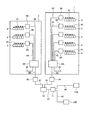
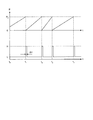
図1は、本発明の一実施の形態である太陽光発電システムの概略構成を示す図である。図2は、集電盤から出力する交流電力の計測例を示す図である。図3は、パルス信号の出力例を示す図である。 FIG. 1 is a diagram showing a schematic configuration of a photovoltaic power generation system according to an embodiment of the present invention. FIG. 2 is a diagram illustrating a measurement example of AC power output from the current collector. FIG. 3 is a diagram illustrating an output example of a pulse signal.
本実施の形態で挙げる太陽光発電システムは、図1に示すように、三相系統1及び単相系統2の2種類の電力系統を備える。三相系統1及び単相系統2の構成は周知であるため、これら電力系統の具体的な説明は省略する。 The solar power generation system mentioned in the present embodiment includes two types of power systems, a three-phase system 1 and a single-phase system 2, as shown in FIG. Since the configurations of the three-phase system 1 and the single-phase system 2 are well known, a specific description of these power systems is omitted.
三相系統1は、三相交流電力を供給する電力系統であり、太陽電池モジュール3、三相パワーコンディショナー5A、及び三相集電盤6A、並びに送電ケーブル41,42,43を備える。
The three-phase system 1 is a power system that supplies three-phase AC power, and includes a
太陽電池モジュール3は、光電変換により発生した直流電力を送電ケーブル41に出力する。出力した直流電力は、送電ケーブル41を通り三相パワーコンディショナ5Aに入力する。三相パワーコンディショナ5Aは、入力した直流電力を三相200Vの交流電力に変換して送電ケーブル42に出力する。三相パワーコンディショナ5Aから出力した三相交流電力は、送電ケーブル42を通って三相集電盤6Aに入力する。三相集電盤6Aは、入力した三相交流電力を1つにまとめて送電ケーブル43に出力する。三相集電盤6Aから出力した三相交流電力は、送電ケーブル43及び図示しない分電盤などを介して負荷装置に供給される。
The
三相集電盤6Aは、図2に示すように、5個の入力側開閉器61、集電配線62、及び1つの出力側開閉器63を備える。なお、図2には、配電方法が三相三線式である場合の三相集電盤6Aの構成例を示している。各三相パワーコンディショナ5Aに接続された送電ケーブル42の一端は、異なる入力側開閉器61に接続している。送電ケーブル42を通る三相交流電力は、接続している入力側開閉器61が閉状態であり、かつ出力側開閉器63が閉状態の場合にのみ、集電配線62及び出力側開閉器63を通って送電ケーブル43に出力する。そのため、各入力側開閉器61の開閉状態の組み合わせを変えることで、送電ケーブル43に出力する三相交流電力の電流値を調節することができる。
As shown in FIG. 2, the three-phase current collection board 6 </ b> A includes five
一方の単相系統2は、単相交流電力を供給する電力系統であり、太陽電池モジュール3、単相パワーコンディショナ5B、及び単相集電盤6B、並びに送電ケーブル41,44,45を備える。
One single-phase system 2 is a power system that supplies single-phase AC power, and includes a
太陽電池モジュール3は、光電変換により発生した直流電力を送電ケーブル41に出力する。出力した直流電力は、送電ケーブル41を通り単相パワーコンディショナ5Bに入力する。単相パワーコンディショナ5Bは、入力した直流電力を単相200Vの交流電力に変換して送電ケーブル44に出力する。単相パワーコンディショナ5Bから出力した単相交流電力は、送電ケーブル44を通って単相集電盤6Bに入力する。単相集電盤6Bは、入力した単相交流電力を1つにまとめて送電ケーブル45に出力する。単相集電盤6Bから出力した単相交流電力は、送電ケーブル45及び図示しない分電盤などを介して負荷装置に供給される。
The
単相集電盤6Bは、三相集電盤6Aと同様の構成になっている。すなわち、図示しない入力側開閉器の開閉状態の組み合わせを変えることで、送電ケーブル45に出力する単相交流電力の電流値を調節することができる。
The single-phase
さて、本実施の形態の太陽光発電システムでは、三相系統1及び単相系統2の発電量を表示するために、図1に示すように、第1の電力計7A、第2の電力計7B、第1の電力計測ケーブル8A、第2の電力計測ケーブル8B、パルス加算器10、パルス分配器11、第1の表示手段12A、及び第2の表示手段12B、並びに信号線91〜95を設けている。
Now, in the photovoltaic power generation system of this embodiment, in order to display the power generation amount of the three-phase system 1 and the single-phase system 2, as shown in FIG. 1, the
第1の電力計7Aは、三相集電盤6Aから送電ケーブル43に出力する三相交流電力の値を計測するものである。この第1の電力計7Aには、三相交流電力の計測及び積算が可能であり、かつ積算した交流電力量と対応付けられたパルス信号を出力可能なものを用いる。また、第1の電力計7Aには、クランプ式と呼ばれる計測方式のものを用いる。
The
第1の電力計7Aによる三相交流電力の計測は、第1の電力計測ケーブル8Aを用いて行う。第1の電力計測ケーブル8Aは、図2に示すように、3本の電圧計測ケーブル81,82,83、及び2本の電流センサ付きケーブル84,85を備える。各電圧計測ケーブル81,82,83はそれぞれ、一端にクリップ部を有する。各クリップ部は、三相集電盤6Aにおける出力側開閉器63の出力端子に取り付ける。電流センサ付きケーブル84,85はそれぞれ、一端に電流センサとしてのクランプセンサ部を有する。各クランプセンサ部は、送電ケーブル43を構成する3本の送電線のうちの2本に取り付ける。
The measurement of the three-phase AC power by the
第1の電力計7Aは、第1の電力計測ケーブル8Aを介して送電ケーブル43の電圧及び電流を計測し、それらの値から瞬時の三相交流電力を算出する。また、第1の電力計7Aは、一定の周期で三相交流電力の算出を繰り返し、三相交流電力を積算する。そして、積算した三相交流電力の値、すなわち三相交流電力量と対応付けられたパルス数のパルス信号を出力する。第1の電力計7Aが出力するパルス信号としては、図3に示すように、積算した交流電力量Pが所定の値PAになるごとに、パルス幅がΔtである1つのパルスを出力する信号が挙げられる。第1の電力計7Aが出力したパルス信号は、信号線91を通ってパルス加算器10に入力する。
The
第2の電力計7Bは、単相集電盤6Bから送電ケーブル45に出力する単相交流電力の値を計測するものである。この第2の電力計7Bには、単相交流電力の計測及び積算が可能であり、かつ積算した交流電力量と対応付けられたパルス信号を出力可能なものを用いる。また、第2の電力計7Bも、クランプ式と呼ばれる計測方式のものを用いる。第2の電力計7Bによる単相交流電力の計測は、第2の電力計測ケーブル8Bを用いて行う。この計測及びパルス信号の出力は、第1の電力計7Aと同様の要領で行う。第2の電力計7Bが出力したパルス信号は、信号線92を通ってパルス加算器10に入力する。
The
パルス加算器10は、入力した2つのパルス信号のパルス数を加算し、その加算したパルス数のパルス信号を出力する。パルス信号における1つのパルスは交流電力量PAに相当する。そのため、パルス加算器10が出力するパルス信号は、三相集電盤6Aから出力した三相交流電力量と単相集電盤6Bから出力した単相交流電力量とを足し合わせた電力量を表している。つまり、パルス加算器10が出力するパルス信号は、三相系統1の発電量と単相系統2の発電量とを足し合わせた発電量に相当する。パルス加算器10が出力したこのパルス信号は、信号線93を通ってパルス分配器11に入力する。
The
パルス分配器11は、入力したパルス信号を2本の信号線94,95のそれぞれに出力する。なお、パルス分配器11が出力するパルス信号は、パルス数が入力したパルス信号と同じであればよい。信号線94に出力したパルス信号は第1の表示手段12Aに入力し、信号線95に出力したパルス信号は第2の表示手段12Bに入力する。
The
第1の表示手段12A及び第2の表示手段12Bは、入力したパルス信号に基づいて発電量を表示する。各表示手段12A,12Bに入力するパルス信号は、パルス数により発電量を表している。そのため、各表示手段12A,12Bは、パルス数と発電量との対応関係を、第1の電力計7A及び第2の電力計7Bと同じ関係に設定する。これにより、各表示手段12A,12Bは、入力したパルス信号から発電量を逆算して表示することができる。
The
このように、本実施の形態の太陽光発電システムは、第1の電力計7A、第2の電力計7B、及びパルス加算器10を用いて発電量を算出している。各電力計7A,7Bは、集電盤6A,6Bから出力した交流電力を計測し、その計測した交流電力を積算して交流電力量を算出する。この交流電力量は、集電盤6A,6Bに接続している複数のパワーコンディショナ5A,5Bが出力した交流電力量を足し合わせたものである。そのため、各電力計7A,7Bが出力するパルス信号のパルス数は、集電盤6A,6Bに接続している複数のパワーコンディショナ5A,5Bの発電量を表している。すなわち、パルス加算器10が出力するパルス信号は、太陽光発電システム全体の発電量を表している。したがって、本実施の形態の太陽光発電システムは、計測システムを使わずに、複数のパワーコンディショナ5A,5Bの発電量を合算して表示することができる。
Thus, the photovoltaic power generation system of the present embodiment calculates the amount of power generation using the
また、本実施の形態の太陽光発電システムは、発電量を表すパルス信号をパルス分配器11により複数の表示手段12A,12Bに分配して出力することができる。そのため、太陽光発電システムの発電量を複数個所で表示することができる。
Moreover, the solar power generation system of this Embodiment can distribute and output the pulse signal showing the electric power generation amount to the plurality of display means 12A and 12B by the
さらに、各電力計7A,7Bが出力するパルス信号は、パルス数で交流電力量を表している。そのため、交流電力量とパルス数との対応関係が共通であれば、電力系統が違っても、ある交流電力量と対応するパルス信号は同じパルス数の信号になる。そのため、本実施の形態の太陽光発電システムは、三相系統1の発電量と単相系統2の発電量とを合算して表示することが容易である。
Further, the pulse signals output from the
さらに、各電力計7A,7Bで計測するのは集電盤6A,6Bから出力した交流電力である。集電盤6A,6Bは、その数がパワーコンディショナ5A,5Bより少ない上、メンテナンスなどの作業をしやすい場所に設置される。そのため、本実施の形態の太陽光発電システムは、発電量の計測に必要な通信ケーブルの敷設工事が容易である。
Further, the AC power output from the
以上、本発明に係る太陽光発電システムの実施の形態を説明したが、本発明は、上記の実施の形態に示した構成に限定されるものではなく、その要旨を逸脱しない範囲において適宜変更可能であることはもちろんである。 As mentioned above, although embodiment of the solar power generation system which concerns on this invention was described, this invention is not limited to the structure shown in said embodiment, In the range which does not deviate from the summary, it can change suitably. Of course.
たとえば、図1には三相系統1及び単相系統2の2つの電力系統を設けた例を示しているが、電力系統の数はこれに限らず、3つ以上にできることはもちろんである。同様に、図1には2つの表示手段12A,12Bを設けた例を示しているが、表示手段の数はこれに限らず、3つ以上にできることはもちろんである。 For example, FIG. 1 shows an example in which two power systems of a three-phase system 1 and a single-phase system 2 are provided, but the number of power systems is not limited to this, and it is needless to say that the number of power systems can be three or more. Similarly, FIG. 1 shows an example in which two display means 12A and 12B are provided, but the number of display means is not limited to this, and it is needless to say that the number can be three or more.
また、第1の電力計7Aとパルス加算器10との接続、及び第2の電力計7Bとパルス加算器10との接続は、有線又は無線のいずれでもよい。同様に、パルス分配器11と第1の表示手段12Aとの接続、及びパルス分配器11と第2の表示手段12Aとの接続は、有線又は無線のいずれでもよい。さらに、パルス加算器10とパルス分配器11とは、有線又は無線で接続される2つの独立した計器ではなく、これらが一体化した計器であってもよい。
The connection between the
また、第1の電力計7A及び第2の電力計7Bが出力するパルス信号、またはパルス加算器10が出力するパルス信号は、表示手段12A,12Bだけでなく、有線又は無線通信により発電量を監視するシステムに送信してもよい。これにより、遠隔地での太陽光発電システムの監視が可能になる。また、第1の電力計7A及び第2の電力計7Bは、上記のクランプ式に限らず、他の計測方式のものであってもよい。
In addition, the pulse signal output from the
さらに、太陽電池モジュール3、三相パワーコンディショナー5A、及び単相パワーコンディショナ5Bは、本設用又は仮設用のいずれであってもよいことはもちろんである。なお、本設用とは、ビルなどの建築物で消費する電力の発電に用いるものである。一方の仮設用とは、工事期間中に消費する電力の発電に用いるものである。
Furthermore, it goes without saying that the
ビルなどの大型建築物に太陽光発電システムを設置する工事では、仮設事務所の照明設備や電動工具などによって多くの電力を消費する。この工事で消費する電力を仮設用の太陽光発電システムにより発電した電力でまかなえば、工事期間中の電力の消費にともなうCO2排出量を削減できる。加えて、本設用である太陽電池モジュール3及び三相パワーコンディショナ5Aの一部を用いて三相系統1を設けた後、その三相系統1で発電する三相交流電力を利用して残りの設置工事を行えば、仮設用の太陽光発電システムを設置するコストを低減できる。
In the construction of installing a photovoltaic power generation system on a large building such as a building, a large amount of electric power is consumed by lighting equipment or electric tools in a temporary office. If the electric power consumed in this construction is covered by the electric power generated by the temporary solar power generation system, the amount of CO 2 emission accompanying the consumption of electric power during the construction period can be reduced. In addition, after the three-phase system 1 is provided by using a part of the
1 三相系統
2 単相系統
3 太陽電池モジュール
41,42,43,44,45 送電ケーブル
5A 三相パワーコンディショナ(パワーコンディショナ)
5B 単相パワーコンディショナ(パワーコンディショナ)
6A 三相集電盤(集電盤)
61 入力側開閉器
62 集電配線
63 出力側開閉器
6B 単相集電盤(集電盤)
7A 第1の電力計
7B 第2の電力計
8A 第1の電力計測ケーブル
8B 第2の電力計測ケーブル
81,82,83 電圧計測ケーブル
84,85 電流計測ケーブル
91,92,93,94,95 信号線
10 パルス加算器
11 パルス分配器
12A 第1の表示手段
12B 第2の表示手段
DESCRIPTION OF SYMBOLS 1 Three-phase system 2 Single-
5B Single-phase power conditioner (power conditioner)
6A Three-phase current collector (current collector)
61 Input side switch 62
7A
Claims (2)
交流電力を計測し、計測した交流電力を積算した交流電力量と対応付けられたパルス数のパルス信号を出力する複数の電力計と、
複数のパルス信号が入力した場合に前記複数のパルス信号のパルス数を加算し、前記加算したパルス数のパルス信号を出力するパルス加算器と、
パルス信号のパルス数と対応付けられた数値を表示する表示手段とを備え、
各集電盤から出力する交流電力を前記電力計で個別に計測し、前記複数の電力計が出力したパルス信号を前記パルス加算器で加算し、前記パルス加算器が出力したパルス信号に基づいた発電量を前記表示手段で表示することを特徴とする太陽光発電システム。 Photovoltaic power generation comprising a plurality of power conditioners that convert DC power into AC power and output, and a plurality of current collectors that collectively output the AC power output from the plurality of power conditioners into one AC power In the system,
A plurality of wattmeters that measure AC power and output a pulse signal having a pulse number associated with the AC power amount obtained by integrating the measured AC power;
A pulse adder that adds the number of pulses of the plurality of pulse signals when a plurality of pulse signals are input, and outputs a pulse signal of the added number of pulses;
Display means for displaying a numerical value associated with the number of pulses of the pulse signal,
AC power output from each current collector is individually measured by the power meter, pulse signals output from the plurality of power meters are added by the pulse adder, and based on the pulse signal output by the pulse adder A photovoltaic power generation system, wherein the amount of power generation is displayed by the display means.
Priority Applications (1)
| Application Number | Priority Date | Filing Date | Title |
|---|---|---|---|
| JP2012123636A JP2013250094A (en) | 2012-05-30 | 2012-05-30 | Solar power generation system |
Applications Claiming Priority (1)
| Application Number | Priority Date | Filing Date | Title |
|---|---|---|---|
| JP2012123636A JP2013250094A (en) | 2012-05-30 | 2012-05-30 | Solar power generation system |
Publications (1)
| Publication Number | Publication Date |
|---|---|
| JP2013250094A true JP2013250094A (en) | 2013-12-12 |
Family
ID=49848935
Family Applications (1)
| Application Number | Title | Priority Date | Filing Date |
|---|---|---|---|
| JP2012123636A Pending JP2013250094A (en) | 2012-05-30 | 2012-05-30 | Solar power generation system |
Country Status (1)
| Country | Link |
|---|---|
| JP (1) | JP2013250094A (en) |
Cited By (4)
| Publication number | Priority date | Publication date | Assignee | Title |
|---|---|---|---|---|
| JP2018530735A (en) * | 2015-07-27 | 2018-10-18 | サンパワー コーポレイション | Solar energy metering, communication and control systems |
| WO2019225309A1 (en) * | 2018-05-24 | 2019-11-28 | 住友電気工業株式会社 | Solar power generation system |
| US20220239251A1 (en) * | 2021-01-22 | 2022-07-28 | Strategic Solar Energy, Llc | System for providing the energy from a single contiguous solar energy structure to at least two different meters |
| JP7418282B2 (en) | 2020-05-19 | 2024-01-19 | クボタ環境エンジニアリング株式会社 | Signal relay device for manhole equipment |
-
2012
- 2012-05-30 JP JP2012123636A patent/JP2013250094A/en active Pending
Cited By (6)
| Publication number | Priority date | Publication date | Assignee | Title |
|---|---|---|---|---|
| JP2018530735A (en) * | 2015-07-27 | 2018-10-18 | サンパワー コーポレイション | Solar energy metering, communication and control systems |
| US10466282B2 (en) | 2015-07-27 | 2019-11-05 | Sunpower Corporation | Solar energy metering, communications, and control system |
| US11231446B2 (en) | 2015-07-27 | 2022-01-25 | Sunpower Corporation | Solar energy metering, communications, and control system |
| WO2019225309A1 (en) * | 2018-05-24 | 2019-11-28 | 住友電気工業株式会社 | Solar power generation system |
| JP7418282B2 (en) | 2020-05-19 | 2024-01-19 | クボタ環境エンジニアリング株式会社 | Signal relay device for manhole equipment |
| US20220239251A1 (en) * | 2021-01-22 | 2022-07-28 | Strategic Solar Energy, Llc | System for providing the energy from a single contiguous solar energy structure to at least two different meters |
Similar Documents
| Publication | Publication Date | Title |
|---|---|---|
| US7546214B2 (en) | System for power sub-metering | |
| US20080082275A1 (en) | System for power sub-metering | |
| JP2016214077A (en) | Method and system | |
| JP5153959B1 (en) | Energy management system | |
| WO2012059061A1 (en) | Method and device for quality-monitoring of high-voltage electrical energy | |
| KR101140277B1 (en) | Electric power data monitoring system using multi telecommunications type multi electric power calculating apparatus without power interruption and electric power data receiver | |
| JP6982107B2 (en) | Smart integrated electricity meter and solar panel power management system that adopts the smart integrated electricity meter | |
| JP2013250094A (en) | Solar power generation system | |
| US20170292999A1 (en) | Transformer monitoring and data analysis systems and methods | |
| JP2014059245A (en) | Electric power display device | |
| JP5433072B1 (en) | Energy management system | |
| KR101295843B1 (en) | Smart Home Distributing Panel | |
| JP5427007B2 (en) | Power monitoring system | |
| KR101254846B1 (en) | Apparatus for measuring generation power and load power for power generation system | |
| JP5177812B2 (en) | Demand monitoring system | |
| CN106468734B (en) | Power monitoring system | |
| WO2017198644A1 (en) | Inverter having a revenue grade meter | |
| WO2008095277A1 (en) | Hybrid renewable power monitor and data logger | |
| JP2013157409A (en) | Photovoltaic power generation system | |
| CN205720386U (en) | A kind of dual pathways contactless below 1000V voltage measuring apparatus | |
| Petrov et al. | Low-cost NB-IoT microgrid power quality monitoring system | |
| JP2014059244A (en) | Power display | |
| JP6081329B2 (en) | Energy management system | |
| KR101120076B1 (en) | Total electric power calculating apparatus using parallel circuit type electric power calculating apparatus without power interruption | |
| JP2014011863A (en) | Photovoltaic power generation system |