JP2013247007A - Socket terminal - Google Patents
Socket terminal Download PDFInfo
- Publication number
- JP2013247007A JP2013247007A JP2012120549A JP2012120549A JP2013247007A JP 2013247007 A JP2013247007 A JP 2013247007A JP 2012120549 A JP2012120549 A JP 2012120549A JP 2012120549 A JP2012120549 A JP 2012120549A JP 2013247007 A JP2013247007 A JP 2013247007A
- Authority
- JP
- Japan
- Prior art keywords
- terminal
- pin terminal
- pin
- socket
- socket terminal
- Prior art date
- Legal status (The legal status is an assumption and is not a legal conclusion. Google has not performed a legal analysis and makes no representation as to the accuracy of the status listed.)
- Granted
Links
Images


Classifications
-
- H—ELECTRICITY
- H01—ELECTRIC ELEMENTS
- H01R—ELECTRICALLY-CONDUCTIVE CONNECTIONS; STRUCTURAL ASSOCIATIONS OF A PLURALITY OF MUTUALLY-INSULATED ELECTRICAL CONNECTING ELEMENTS; COUPLING DEVICES; CURRENT COLLECTORS
- H01R24/00—Two-part coupling devices, or either of their cooperating parts, characterised by their overall structure
- H01R24/76—Two-part coupling devices, or either of their cooperating parts, characterised by their overall structure with sockets, clips or analogous contacts and secured to apparatus or structure, e.g. to a wall
-
- H—ELECTRICITY
- H01—ELECTRIC ELEMENTS
- H01R—ELECTRICALLY-CONDUCTIVE CONNECTIONS; STRUCTURAL ASSOCIATIONS OF A PLURALITY OF MUTUALLY-INSULATED ELECTRICAL CONNECTING ELEMENTS; COUPLING DEVICES; CURRENT COLLECTORS
- H01R13/00—Details of coupling devices of the kinds covered by groups H01R12/70 or H01R24/00 - H01R33/00
- H01R13/02—Contact members
- H01R13/10—Sockets for co-operation with pins or blades
- H01R13/11—Resilient sockets
- H01R13/111—Resilient sockets co-operating with pins having a circular transverse section
-
- H—ELECTRICITY
- H01—ELECTRIC ELEMENTS
- H01R—ELECTRICALLY-CONDUCTIVE CONNECTIONS; STRUCTURAL ASSOCIATIONS OF A PLURALITY OF MUTUALLY-INSULATED ELECTRICAL CONNECTING ELEMENTS; COUPLING DEVICES; CURRENT COLLECTORS
- H01R13/00—Details of coupling devices of the kinds covered by groups H01R12/70 or H01R24/00 - H01R33/00
- H01R13/02—Contact members
- H01R13/15—Pins, blades or sockets having separate spring member for producing or increasing contact pressure
- H01R13/18—Pins, blades or sockets having separate spring member for producing or increasing contact pressure with the spring member surrounding the socket
Abstract
Description
本発明は、ソケット端子に関する。 The present invention relates to a socket terminal.
従来、例えば樹脂製のハウジングに形成されたキャビティ内に収容されるソケット端子として、図21に記載のものが知られている。このソケット端子1は、相手側のピン端子2が挿入される筒部3を備えており、筒部3は、環状の基部4と、基部4から相手側のピン端子2に向けて延びる複数の端子片5とを備える。端子片5は先端側が僅かに縮径されており、ピン端子2は端子片5を押し広げるように弾性変形させつつ筒部3内に挿入され、互いの接点において導通接続される。
Conventionally, for example, a socket terminal shown in FIG. 21 is known as a socket terminal accommodated in a cavity formed in a resin housing. The socket terminal 1 includes a cylindrical portion 3 into which a
上述した従来のソケット端子1では、ピン端子2とソケット端子1とは、筒部3(ピン端子2)の軸方向において同一面(図21のY面)で弾性接触し、導通接続されるため、振動等によってピン端子2の径方向に外力が加えられた場合、ピン端子2の中心軸が筒部3の中心軸に対して傾き、その結果、ピン端子2とソケット端子1との接触点が移動して接触抵抗が変化する虞がある。
In the conventional socket terminal 1 described above, the
本発明は上記のような事情に基づいて完成されたものであって、ピン端子を安定的に保持可能なソケット端子を提供することを目的とするものである。 The present invention has been completed based on the above circumstances, and an object thereof is to provide a socket terminal capable of stably holding a pin terminal.
上記課題を解決するためになされた本発明は、相手側のピン端子と嵌合接続されるソケット端子であって、前記ピン端子と嵌合可能な筒部を備え、前記筒部は、前記ピン端子との嵌合始端とは反対側に設けられた基部と、前記基部から前記ピン端子に向けて前記筒部の軸方向に延びると共に前記筒部の周方向に間隔を空けて並んで設けられて前記筒部内に嵌合された前記ピン端子の外周面に対して弾性接触可能な複数の端子片とを備え、前記基部側には前記ピン端子に向けて前記筒部の径方向に突出して前記ピン端子の外周面を保持する複数の保持部を有するところに特徴を有する。 The present invention made to solve the above-mentioned problems is a socket terminal that is fitted and connected to a mating pin terminal, and includes a cylindrical portion that can be fitted to the pin terminal, and the cylindrical portion includes the pin A base provided on the opposite side of the fitting start end with the terminal, and extending in the axial direction of the cylindrical portion from the base toward the pin terminal and arranged side by side in the circumferential direction of the cylindrical portion A plurality of terminal pieces elastically contactable with the outer peripheral surface of the pin terminal fitted in the cylindrical portion, and projecting in a radial direction of the cylindrical portion toward the pin terminal on the base side. It has a feature in that it has a plurality of holding portions for holding the outer peripheral surface of the pin terminal.
本発明のソケット端子によれば、ピン端子の基部側を複数の端子片によって弾性接触するとともに、先端側を、筒部の基部側に設けられた複数の保持部により保持する構成であるから、ソケット端子(筒部)の軸方向における少なくとも二箇所でピン端子を保持することとなる。従って、ピン端子の径方向に外力が加えられた場合でも、ピン端子がソケット端子に対して従来のように簡単に傾いてしまうことがなく、安定的に保持可能となる。 According to the socket terminal of the present invention, the base side of the pin terminal is elastically contacted by the plurality of terminal pieces, and the distal end side is held by the plurality of holding portions provided on the base side of the cylindrical portion. The pin terminal is held at at least two locations in the axial direction of the socket terminal (cylinder portion). Therefore, even when an external force is applied in the radial direction of the pin terminal, the pin terminal is not easily inclined with respect to the socket terminal as in the prior art, and can be stably held.
なお、保持部は、例えば基部の外周面側から押し出して形成された膨出部としてもよい。あるいは、筒部の径方向外側に弾性変形可能な弾性片としてもよい。 The holding portion may be a bulging portion formed by being extruded from the outer peripheral surface side of the base portion, for example. Or it is good also as an elastic piece which can be elastically deformed to the radial direction outer side of a cylinder part.
また、複数の保持部を基部の内周面のうち同一周上に設けるようにしてもよい。このような構成とすると、ピン端子の先端側の外周面を均等な状態で保持可能となるので、より安定性が向上する。 Moreover, you may make it provide several holding | maintenance parts on the same periphery among the internal peripheral surfaces of a base. With such a configuration, the outer peripheral surface on the tip end side of the pin terminal can be held in a uniform state, so that the stability is further improved.
また、保持部を基部のうち互いに隣り合う端子片の間に設ける構成としてもよい。ピン端子の基部側は、複数の端子片により弾性接触されているが、互いに隣り合う端子片の間に保持部を設けることにより、端子片の接触部の間となる軸線上でピン端子の先端側を保持することが可能となるから、さらに安定性が向上する。 Moreover, it is good also as a structure which provides a holding | maintenance part between mutually adjacent terminal pieces among bases. The base side of the pin terminal is elastically contacted by a plurality of terminal pieces, but by providing a holding part between adjacent terminal pieces, the tip of the pin terminal on the axis line between the contact parts of the terminal pieces Since it becomes possible to hold | maintain the side, stability improves further.
さらに、ピン端子と保持部とを電気的絶縁状態としてもよい。このようにすると、ピン端子とソケット端子とは端子片の接触部のみで電気的に接続されるから、電気的接続状態を安定させることができる。 Furthermore, the pin terminal and the holding portion may be electrically insulated. If it does in this way, since a pin terminal and a socket terminal are electrically connected only by the contact part of a terminal piece, an electrical connection state can be stabilized.
<実施形態1>
本発明の実施形態1を図1ないし図8によって説明する。本実施形態のソケット端子10は、相手側のピン端子20と嵌合可能とされている。
<Embodiment 1>
A first embodiment of the present invention will be described with reference to FIGS. The
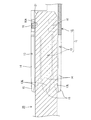
ソケット端子10は、図示しない電線の芯線に導通接続可能な接続部(図示せず)の他端側(図1における左方)に、相手側のピン端子20と嵌合可能な筒部11が設けられたものである。筒部11は全体として略円筒形状をなしており、その軸線は、ピン端子20との嵌合方向に延びている。筒部11は、環状の基部12と、この基部12からピン端子20との嵌合方向前方(図1の左側)に向けて延びると共に、筒部11の周方向に間隔を空けて並んで設けられる複数(本実施形態では6つ)の端子片13とからなる。
The
基部12は、金属製の板状部材の端縁同士を付き合わせるように断面略C字状に曲げ加工することで、環状に形成されている。各端子片13は、基部12からピン端子20との嵌合方向前方側に向けて筒部11の軸線方向に沿って先細かつ片持ち状に延出されており、先端側にかけて縮径方向に傾斜するテーパ部14と、このテーパ部14のさらに先端側に設けられてやや拡径する案内部15とから構成されている。また端子片13は、筒部11の径方向に弾性撓み変形可能とされている。テーパ部14と案内部15との境界13L付近の自然状態における内径は、ピン端子20の外形寸法よりやや小さく設定されており、ピン端子20が筒部11内に挿入された際にはこの境界13L付近がピン端子20の外周に弾性的に接触することにより互いに導通接続される。
The
なお、ソケット端子10は、金属製の板状部材、例えば、銅合金製の板状部材を所定形状にプレス成形したものから形成されており、その表面には、銀、錫等のメッキが施されている。
The
基部12には、弾性保持片16(本発明の保持部および弾性片の一例)が設けられている。弾性保持片16は、図1ないし図4に示すように、基部12の周方向に沿って片持ち状の弾性片を筒部11の径方向内側に切り起こすことにより形成されたものであって、本実施形態では等間隔に3つ設けられている。すなわち、本実施形態において、端子片13はそれぞれ周方向に60°の角度間隔で計6本形成されているのに対し、弾性保持片16は周方向に120°の角度間隔で計3つ形成されている(図4参照)。またこれら3つの弾性保持片16は、隣り合う端子片13の間の軸線上に位置するように形成されている。具体的には、例えば図2に示すように、6本の端子片13を基部12の付き合わせ部から順に13A,13B,13C,13D,13E,13Fとした場合に、弾性保持片16は13Bと13Cとの間、13Dと13Eとの間、および、13Fと13Aとの間の3箇所に形成されている。なお、弾性保持片16の先端面16Aを筒部11の周方向に繋いで作る面の内径は、ピン端子20の外形寸法と同等か、やや小さくなるように設定されている(図4参照)。
The
一方、ピン端子20は、例えば図6に示すように、断面円形状をなしており、先端部にはやや縮径された案内面21が形成されている(図5および図7参照)。また、この案内面21を含む先端部には、指触防止用の絶縁部材22が被覆されている。この絶縁部材22は、ソケット端子10とピン端子20とが正規の嵌合状態とされた際に、少なくともソケット端子10の弾性保持片16が当接する位置までピン端子20の先端部を覆う長さに設定されている(図5参照)。なおピン端子20の他端側は、図示しない電線、又は図示しない機器に接続されている。
On the other hand, the
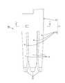
本実施形態のソケット端子10とピン端子20とを嵌合する際には、まず、ピン端子20をその先端側から筒部11内に挿入する。この時、ピン端子20の案内面21はソケット端子10の案内部15に案内されつつ、筒部11内に速やかに挿入される。またこの時、ソケット端子10の複数の端子片13A〜13Fはピン端子20により押し広げられて拡開変形し、これにより端子片13のうちテーパ部14と案内部15との境界13L付近がピン端子20の外周面に弾性的に接触して、ピン端子20とソケット端子10との電気的接続が行われる。
When fitting the
ピン端子20が正規嵌合位置に達すると、図7及び図8に示すように、基部12の内周側に突出している弾性保持片16の先端面16Aがピン端子20の外周面(より詳しくは、ピン端子20に被覆された絶縁部材22)に当接、あるいは、弾性接触し、ピン端子20の先端部を3方向から保持する。
When the
このような本実施形態のソケット端子10によれば、ピン端子20はソケット端子10によって、基部側が端子片13に弾性接触されるだけでなく、先端側が弾性保持片16により保持され、軸方向における2箇所で筒部11内に保持されることとなる。従って、ピン端子20の径方向に対して外力が加えられた場合でも、ソケット端子10に対してこじれることがなく、ピン端子20とソケット端子10との間の電気的な接続を安定的なものとすることが可能となる。また、3つの弾性保持片16を筒部11(基部12)の同一周上、すなわち、筒部11の軸方向において同位置に設けたことにより、ピン端子20は径方向に均等に保持された状態となるから、ピン端子20と端子片13との導通接続部の接触圧力を一定に維持可能となり、ピン端子20とソケット端子10との間の電気的な接続をより一層安定的なものとすることができる。さらにこれらの弾性保持片16は、基部12のうち、互いに隣り合う二つの端子片13の間の軸線上に設ける構成としたから、ピン端子20の基部側と先端側において周方向の互いに異なる位置で保持されることとなり、これによっても、ピン端子20を筒部11内により安定的に保持することが可能となる。
According to the
また、本実施形態では、ピン端子20の先端に指触防止用の絶縁部材22が設けられていることを利用して、その絶縁部材22に弾性保持片16を接触させる構成としているから、その弾性保持片16部分でピン端子20との間では電気的絶縁状態となっている。このため、ソケット端子10とピン端子20とは、端子片13の先端側のみで接触することになり、電気的接触状態が安定する。
Further, in the present embodiment, since the insulating
<実施形態2>
次に、本発明の実施形態2を図9ないし図12を参照して説明する。本実施形態においては、上記実施形態1と同様の部分は同一符号を付し、説明を省略する。
<
Next, a second embodiment of the present invention will be described with reference to FIGS. In the present embodiment, the same parts as those in the first embodiment are denoted by the same reference numerals, and description thereof is omitted.
本実施形態のソケット端子30は、上記実施形態1とは弾性保持片36の向きが異なる。本実施形態の弾性保持片36は、筒部11の軸方向に沿ってかつ嵌合方向後方に向けて片持ち状に切り出された弾性片の先端部を、筒部11の径方向内側に向けてほぼ直角に曲げ加工することにより形成されたものであって、上記実施形態1と同様に周方向において等間隔に3つ、つまり、円周方向に120°ずつ離れた箇所に合計3つ形成されている。またこれら3つの弾性保持片36は、隣り合う端子片13の間の軸線上に位置するように形成されている。具体的には、例えば図10に示すように、6本の端子片13を基部12の付き合わせ部から順に13A,13B,13C,13D,13E,13Fとした場合に、弾性保持片16は13Aと13Bとの間、13Cと13Dとの間、および、13Eと13Fとの間の3箇所に形成されている。なお、弾性保持片36の先端面36Aを筒部11の周方向に繋いで作る面の内径は、ピン端子20の外形寸法と同等か、やや小さくなるように設定されている。
The
このような本実施形態のソケット端子30によっても、上記実施形態1と同様に、ピン端子20とソケット端子30との間の電気的な接続を安定的なものとすることができる。
Also with the
<実施形態3>
本発明の実施形態3のソケット端子40は、上記実施形態1,2とは弾性保持片46の向きが異なる。弾性保持片46は、図13ないし図16に示すように、筒部11の軸方向に沿ってかつ嵌合方向前方に向けて片持ち状に切り出された弾性片の先端部を、筒部11の径方向外側に向けて斜めに曲げ加工することにより形成されたものであって、上記実施形態2と同様に周方向に等間隔に3つ、つまり、円周方向に120°ずつ離れた箇所に合計3つ形成されている。弾性保持片46は、図15に示すように、全体が筒部11の内側に向けてやや傾斜されている。弾性保持片46の先端の曲げ部46Aを筒部11の周方向に繋いで作る面の内径は、ピン端子20の外形寸法と同等か、やや小さくなるように設定されている。
<Embodiment 3>
The
このような本実施形態のソケット端子40によっても、上記実施形態1および2と同様に、ピン端子20とソケット端子40との間の電気的な接続を安定的なものとすることができる。
<実施形態4>
本発明の実施形態4のソケット端子50は、上記実施形態1ないし3とは弾性保持片の形態が異なる。
Also with the
<Embodiment 4>
The
本実施形態においては、図17ないし図20に示すように、基部12の内周面に、ピン端子20の外周面を保持する凸状の膨出部56が形成されている。膨出部56は、基部12を径方向内方に向けて押し出すことにより形成されている。またこの膨出部56は、筒部11の円周方向に120°ずつ離れた箇所に合計3つ形成されている。膨出部56の端面56Aを筒部11の周方向に繋いで作る面の内径は、ピン端子20の外形寸法とほぼ同等とされている。
In the present embodiment, as shown in FIGS. 17 to 20, a convex bulging
このような本実施形態のソケット端子50によっても、上記実施形態1ないし3と同様に、ピン端子20とソケット端子50との間の電気的な接続を安定的なものとすることができる。
Also with the
<他の実施形態>
本発明は上記記述及び図面によって説明した実施形態に限定されるものではなく、例えば次のような実施形態も本発明の技術的範囲に含まれる。
<Other embodiments>
The present invention is not limited to the embodiments described with reference to the above description and drawings. For example, the following embodiments are also included in the technical scope of the present invention.
(1)上記各実施形態では、端子片13は6つである例を示したが、端子片13の数は上記実施形態に限らない。
(1) In each of the above embodiments, the example in which the number of the
(2)上記各実施形態では、弾性保持片16,36,46または膨出部56が筒部11の周方向に120°ずつ離れた位置に合計3つ形成されている例を示したが、これらの位置や数は上記実施形態に限らない。
(2) In each of the above embodiments, the
(3)また、上記各実施形態では、弾性保持片16,36,46または膨出部56は互いに隣り合う端子片13,13の間の軸線上に位置する構成としたが、端子片13の中心線上やその他の位置に設ける構成としてもよく、上記実施形態に限るものではない。
(3) In the above embodiments, the
(4)上記各実施形態では、弾性保持片16,36,46または膨出部56を基部12の同一周上に設ける構成としたが、筒部11の軸方向にずれた位置に設ける構成としてもよい。
(4) In each of the above embodiments, the
(5)上記実施形態4では、膨出部56を凸状としたが、例えば半球状の突部としてピン端子20と点接触させる構成とすることもできる。
(5) In the said Embodiment 4, although the bulging
(6)上記各実施形態では、金属製のソケット端子自体に保持部(弾性保持片16,36,46または膨出部56)を設ける構成を例示したが、金属製のソケット端子を樹脂ハウジングに装着してソケット端子として利用する場合には、その樹脂ハウジングに保持部を形成するようにしても良い。
(6) In each of the above embodiments, the configuration in which the holding portion (the
(7)上記各実施形態では、弾性保持片16,36,46または膨出部56とピン端子とを電気的絶縁状態とする例を示したが、絶縁部材を短くして電気的接続状態とする構成としてもよい。
(7) In each of the above embodiments, the example in which the
10,30,40,50…ソケット端子
11…筒部
12…基部
13…端子片
14…テーパ部
15…案内部
16,36,46…弾性保持片(保持部・弾性片)
20…ピン端子
21…案内面
22…絶縁部材
56…膨出部(保持部)
DESCRIPTION OF
20 ... pin terminal 21 ... guide
Claims (6)
Priority Applications (5)
| Application Number | Priority Date | Filing Date | Title |
|---|---|---|---|
| JP2012120549A JP5995062B2 (en) | 2012-05-28 | 2012-05-28 | Socket terminal |
| PCT/JP2013/063932 WO2013179933A1 (en) | 2012-05-28 | 2013-05-20 | Socket terminal |
| DE112013002690.2T DE112013002690B4 (en) | 2012-05-28 | 2013-05-20 | Female connector |
| CN201380026413.0A CN104335426B (en) | 2012-05-28 | 2013-05-20 | Female terminal |
| US14/397,909 US9444168B2 (en) | 2012-05-28 | 2013-05-20 | Socket terminal |
Applications Claiming Priority (1)
| Application Number | Priority Date | Filing Date | Title |
|---|---|---|---|
| JP2012120549A JP5995062B2 (en) | 2012-05-28 | 2012-05-28 | Socket terminal |
Publications (2)
| Publication Number | Publication Date |
|---|---|
| JP2013247007A true JP2013247007A (en) | 2013-12-09 |
| JP5995062B2 JP5995062B2 (en) | 2016-09-21 |
Family
ID=49673135
Family Applications (1)
| Application Number | Title | Priority Date | Filing Date |
|---|---|---|---|
| JP2012120549A Expired - Fee Related JP5995062B2 (en) | 2012-05-28 | 2012-05-28 | Socket terminal |
Country Status (5)
| Country | Link |
|---|---|
| US (1) | US9444168B2 (en) |
| JP (1) | JP5995062B2 (en) |
| CN (1) | CN104335426B (en) |
| DE (1) | DE112013002690B4 (en) |
| WO (1) | WO2013179933A1 (en) |
Cited By (2)
| Publication number | Priority date | Publication date | Assignee | Title |
|---|---|---|---|---|
| US11381021B2 (en) | 2019-10-07 | 2022-07-05 | Japan Aviation Electronics Industry, Limited | Socket contact and connector |
| JP7446982B2 (en) | 2020-11-24 | 2024-03-11 | 株式会社フジクラ | terminal |
Families Citing this family (12)
| Publication number | Priority date | Publication date | Assignee | Title |
|---|---|---|---|---|
| EP2833385B1 (en) * | 2013-07-30 | 2017-05-03 | ABB Schweiz AG | Connecting device for a switchgear apparatus |
| CN107112673A (en) * | 2014-10-10 | 2017-08-29 | 株式会社藤仓 | Terminal and its manufacture method |
| JP6311939B2 (en) * | 2015-03-19 | 2018-04-18 | 株式会社オートネットワーク技術研究所 | Method for manufacturing female terminal and female terminal |
| US9905953B1 (en) | 2016-09-30 | 2018-02-27 | Slobodan Pavlovic | High power spring-actuated electrical connector |
| US10892576B2 (en) * | 2016-11-17 | 2021-01-12 | Molex, Llc | Floating socket connector |
| US9917390B1 (en) | 2016-12-13 | 2018-03-13 | Carlisle Interconnect Technologies, Inc. | Multiple piece contact for an electrical connector |
| JP6989715B2 (en) | 2018-02-26 | 2022-01-05 | ロイヤル プレシジョン プロダクツ,エルエルシー | Spring-loaded electrical connectors for high power applications |
| WO2019237009A1 (en) | 2018-06-07 | 2019-12-12 | Royal Precision Products, Llc | Electrical connector system with internal spring component |
| CN110190443B (en) * | 2018-11-30 | 2021-11-16 | 中航光电科技股份有限公司 | Contact and high-speed connector |
| US11721942B2 (en) | 2019-09-09 | 2023-08-08 | Eaton Intelligent Power Limited | Connector system for a component in a power management system in a motor vehicle |
| CN114787815A (en) | 2019-09-09 | 2022-07-22 | 伊顿智能动力有限公司 | Connector recording system with readable and recordable indicia |
| DE112021003303T5 (en) | 2020-07-29 | 2023-05-25 | Eaton Intelligent Power Limited | ELECTRICAL CONNECTION SYSTEM WITH CYLINDRICAL CLAMP BODY |
Citations (4)
| Publication number | Priority date | Publication date | Assignee | Title |
|---|---|---|---|---|
| JP2003317843A (en) * | 2002-04-19 | 2003-11-07 | Bosch Automotive Systems Corp | Connector |
| JP2010113962A (en) * | 2008-11-06 | 2010-05-20 | Autonetworks Technologies Ltd | Socket terminal |
| WO2010149282A1 (en) * | 2009-06-25 | 2010-12-29 | Lapp Engineering & Co. | Electrical plug connector |
| JP2012022826A (en) * | 2010-07-13 | 2012-02-02 | Japan Aviation Electronics Industry Ltd | Socket contact |
Family Cites Families (12)
| Publication number | Priority date | Publication date | Assignee | Title |
|---|---|---|---|---|
| DE9211819U1 (en) * | 1992-07-07 | 1993-11-04 | Grote & Hartmann | Electrical contact element |
| US5509814A (en) | 1993-06-01 | 1996-04-23 | Itt Corporation | Socket contact for mounting in a hole of a device |
| GB9424117D0 (en) | 1994-11-28 | 1995-01-18 | Amp Gmbh | Receptacle contact for pressed screen contact pins |
| JP4075825B2 (en) * | 2004-02-26 | 2008-04-16 | 住友電装株式会社 | Female terminal bracket |
| US7374460B1 (en) * | 2007-04-17 | 2008-05-20 | Traxxas Lp | Electrical connector assembly |
| US7479028B1 (en) * | 2007-12-18 | 2009-01-20 | Pottorff Lawrence P | Charger connector apparatus |
| JP5447971B2 (en) * | 2010-04-08 | 2014-03-19 | 住友電装株式会社 | Terminal bracket connection structure |
| DE102010023423A1 (en) * | 2010-06-11 | 2011-12-15 | Wago Verwaltungsgesellschaft Mbh | Spring clamp and terminal block |
| US8678867B2 (en) * | 2011-10-31 | 2014-03-25 | Lear Corporation | Electrical terminal and receptacle assembly |
| US8864535B2 (en) * | 2012-08-13 | 2014-10-21 | Tyco Electronics Corporation | Poke-in contact with multiple contact sections to accept and terminate a respective wire from varied directions |
| US8998655B2 (en) * | 2012-09-24 | 2015-04-07 | Lear Corporation | Electrical terminal |
| JP5296915B1 (en) * | 2012-11-15 | 2013-09-25 | イリソ電子工業株式会社 | Electrical connection terminal and connector provided with the same |
-
2012
- 2012-05-28 JP JP2012120549A patent/JP5995062B2/en not_active Expired - Fee Related
-
2013
- 2013-05-20 CN CN201380026413.0A patent/CN104335426B/en not_active Expired - Fee Related
- 2013-05-20 WO PCT/JP2013/063932 patent/WO2013179933A1/en active Application Filing
- 2013-05-20 DE DE112013002690.2T patent/DE112013002690B4/en not_active Expired - Fee Related
- 2013-05-20 US US14/397,909 patent/US9444168B2/en active Active
Patent Citations (4)
| Publication number | Priority date | Publication date | Assignee | Title |
|---|---|---|---|---|
| JP2003317843A (en) * | 2002-04-19 | 2003-11-07 | Bosch Automotive Systems Corp | Connector |
| JP2010113962A (en) * | 2008-11-06 | 2010-05-20 | Autonetworks Technologies Ltd | Socket terminal |
| WO2010149282A1 (en) * | 2009-06-25 | 2010-12-29 | Lapp Engineering & Co. | Electrical plug connector |
| JP2012022826A (en) * | 2010-07-13 | 2012-02-02 | Japan Aviation Electronics Industry Ltd | Socket contact |
Cited By (3)
| Publication number | Priority date | Publication date | Assignee | Title |
|---|---|---|---|---|
| US11381021B2 (en) | 2019-10-07 | 2022-07-05 | Japan Aviation Electronics Industry, Limited | Socket contact and connector |
| US11942714B2 (en) | 2019-10-07 | 2024-03-26 | Japan Aviation Electronics Industry, Limited | Socket contact and connector |
| JP7446982B2 (en) | 2020-11-24 | 2024-03-11 | 株式会社フジクラ | terminal |
Also Published As
| Publication number | Publication date |
|---|---|
| CN104335426B (en) | 2017-06-13 |
| US9444168B2 (en) | 2016-09-13 |
| WO2013179933A1 (en) | 2013-12-05 |
| DE112013002690T5 (en) | 2015-02-26 |
| DE112013002690B4 (en) | 2020-06-10 |
| CN104335426A (en) | 2015-02-04 |
| US20150126076A1 (en) | 2015-05-07 |
| JP5995062B2 (en) | 2016-09-21 |
Similar Documents
| Publication | Publication Date | Title |
|---|---|---|
| JP5995062B2 (en) | Socket terminal | |
| KR101809013B1 (en) | Rotatable plug-type connector | |
| JP7005507B2 (en) | Electrical plug connector | |
| EP2961004A1 (en) | Radio-frequency coaxial electric connector with contact element | |
| JP2019067719A (en) | Spring connector | |
| JP2018514061A (en) | Method for the manufacture of plug connector configurations | |
| JP6278024B2 (en) | connector | |
| CN106961037B (en) | Electric connector using point contact type electric connector contact element | |
| JP2017010703A (en) | Terminal and terminal connection structure | |
| WO2018163814A1 (en) | Male terminal | |
| WO2015029731A1 (en) | Connector | |
| JP2019526923A (en) | Electrical contact for a plug connector having a rotatable rolling contact and electrical plug-in connection with such a contact | |
| JP2011071043A (en) | Electric wire connection tool | |
| JP2018195439A (en) | Terminal | |
| JP6272125B2 (en) | connector | |
| JP2016081734A (en) | Terminal fitting and connector | |
| WO2013190947A1 (en) | Socket terminal | |
| JP2018160393A (en) | Electric connector | |
| JP6555286B2 (en) | Jack | |
| JP5354294B2 (en) | Female terminal bracket | |
| JP2021002447A (en) | Plug, and connection structure between plug and jack | |
| JP2017098002A (en) | Cable assembly and method for manufacturing cable assembly | |
| JP2014170750A (en) | Bush or plug for high current plug-in connector with contact plate ring including contact plate having 8-shaped cross section | |
| JP3220114U (en) | Plug and plug adapter | |
| JP2014220120A (en) | Connector |
Legal Events
| Date | Code | Title | Description |
|---|---|---|---|
| A621 | Written request for application examination |
Free format text: JAPANESE INTERMEDIATE CODE: A621 Effective date: 20140530 |
|
| A131 | Notification of reasons for refusal |
Free format text: JAPANESE INTERMEDIATE CODE: A131 Effective date: 20150818 |
|
| A521 | Request for written amendment filed |
Free format text: JAPANESE INTERMEDIATE CODE: A523 Effective date: 20150918 |
|
| A131 | Notification of reasons for refusal |
Free format text: JAPANESE INTERMEDIATE CODE: A131 Effective date: 20160216 |
|
| A521 | Request for written amendment filed |
Free format text: JAPANESE INTERMEDIATE CODE: A523 Effective date: 20160413 |
|
| TRDD | Decision of grant or rejection written | ||
| A01 | Written decision to grant a patent or to grant a registration (utility model) |
Free format text: JAPANESE INTERMEDIATE CODE: A01 Effective date: 20160728 |
|
| A61 | First payment of annual fees (during grant procedure) |
Free format text: JAPANESE INTERMEDIATE CODE: A61 Effective date: 20160810 |
|
| R150 | Certificate of patent or registration of utility model |
Ref document number: 5995062 Country of ref document: JP Free format text: JAPANESE INTERMEDIATE CODE: R150 |
|
| LAPS | Cancellation because of no payment of annual fees |