JP2013242101A - Burner and gas turbine combustor - Google Patents
Burner and gas turbine combustor Download PDFInfo
- Publication number
- JP2013242101A JP2013242101A JP2012116264A JP2012116264A JP2013242101A JP 2013242101 A JP2013242101 A JP 2013242101A JP 2012116264 A JP2012116264 A JP 2012116264A JP 2012116264 A JP2012116264 A JP 2012116264A JP 2013242101 A JP2013242101 A JP 2013242101A
- Authority
- JP
- Japan
- Prior art keywords
- burner
- air
- fuel
- chamber
- combustion
- Prior art date
- Legal status (The legal status is an assumption and is not a legal conclusion. Google has not performed a legal analysis and makes no representation as to the accuracy of the status listed.)
- Granted
Links
Images


Abstract
Description
本発明は、燃料と空気との混合気を燃焼部で燃焼させて、火炎を形成するためのバーナ等に関する。 The present invention relates to a burner or the like for forming a flame by burning a mixture of fuel and air in a combustion section.
ガスタービン燃焼器等の燃焼器のシンプル低NOx化の要請に伴い、本発明の出願人は、旋回羽根を廃したバーナを開発して既に出願している(特許文献1参照)。そして、先行技術に係るバーナについて簡単に説明すると、次のようになる。 With the demand for simple NOx reduction in combustors such as gas turbine combustors, the applicant of the present invention has already developed and applied for a burner with no swirl vanes (see Patent Document 1). Then, the burner according to the prior art will be briefly described as follows.
先行技術に係るバーナは、筒状のバーナ本体を備えており、このバーナ本体は、内側に、燃焼部に連通したバーナ室を有している。また、バーナ本体の外周部には、接線方向からバーナ室に空気を導入する第1空気導入孔が形成されており、バーナ本体における第1空気導入孔の上流側(バーナ本体の底部)には、バーナ室に空気を導入する第2空気導入孔が形成されている。そして、バーナ本体の中央部には、燃焼部側へ向かって燃料を噴射(噴霧)する燃料噴射弁が設けられている。 The burner according to the prior art includes a cylindrical burner main body, and this burner main body has a burner chamber communicating with the combustion section on the inner side. Further, a first air introduction hole for introducing air into the burner chamber from the tangential direction is formed in the outer peripheral portion of the burner body, and on the upstream side of the first air introduction hole in the burner body (the bottom of the burner body). A second air introduction hole for introducing air into the burner chamber is formed. A fuel injection valve that injects (sprays) fuel toward the combustion portion side is provided at the center of the burner body.
従って、第1空気導入孔から空気をバーナ室に導入して強い旋回流を形成しかつ第2空気導入孔から空気をバーナ室に導入して前記強い旋回流に衝突させることにより、燃料噴射弁の近傍において、前記強い旋回流を部分的に破壊して強い乱流(強い乱流場)を形成する。また、燃料噴射弁の近傍に強い乱流場を形成した状態で、燃料噴射弁から燃焼部側に向かって燃料を噴射する。これにより、燃料と空気の混合を促進しつつ、燃焼部において着火によって混合気を燃焼させて、火炎を形成することができる。 Therefore, by introducing air into the burner chamber from the first air introduction hole to form a strong swirl flow and introducing air into the burner chamber from the second air introduction hole to collide with the strong swirl flow, the fuel injection valve In the vicinity of, the strong swirling flow is partially broken to form a strong turbulent flow (strong turbulent flow field). In addition, fuel is injected from the fuel injection valve toward the combustion section in a state where a strong turbulent flow field is formed in the vicinity of the fuel injection valve. As a result, while promoting the mixing of fuel and air, the air-fuel mixture can be burned by ignition in the combustion section to form a flame.
ところで、バーナ室から燃焼部に流出する流れは強い旋回成分を有してあって、径方向(放射方向)に拡大する傾向にあり、旋回羽根を備えたバーナのように燃料噴射弁の下流側近傍に逆流領域を形成することができない。そのため、燃料噴射弁の下流側近傍の流速(局所流速)が速くなって、火炎基部位置での火炎吹き消え限界領域が狭くなり、バーナの保炎性、ガスタービン燃焼器等の燃焼器の燃焼安定性を高いレベルまで確保することが困難であるという問題がある。なお、火炎吹き消え限界領域とは、ガスが反応帯を通過する時間(流体力学特性時間)に比べて、燃焼の化学反応にかかる時間(化学反応特性時間)が短く、燃料と空気の混合及び燃焼反応が維持される領域のことをいう。 By the way, the flow flowing out from the burner chamber to the combustion section has a strong swirl component and tends to expand in the radial direction (radial direction), and is downstream of the fuel injection valve like a burner having swirl vanes. A backflow region cannot be formed in the vicinity. Therefore, the flow velocity (local flow velocity) in the vicinity of the downstream side of the fuel injection valve is increased, the flame blow-off limit region at the flame base position is narrowed, the flame holding property of the burner, and the combustion of a combustor such as a gas turbine combustor There is a problem that it is difficult to ensure stability to a high level. It should be noted that the flame blow-out limit region is shorter in the time required for the chemical reaction of combustion (chemical reaction characteristic time) than the time required for the gas to pass through the reaction zone (hydrodynamic characteristic time). It refers to the region where the combustion reaction is maintained.
特に、航空用ガスタービン燃焼器に用いられるバーナの場合には、エンジン作動状態によってバーナの入口状態(入口条件)が大きく変化し、エンジン作動状態が低温低圧状態(低温低圧条件)でかつ高マッハ状態(高マッハ条件)のときに、前述の問題が顕著になる。 In particular, in the case of a burner used in an aircraft gas turbine combustor, the inlet state (inlet condition) of the burner varies greatly depending on the engine operating state, and the engine operating state is in a low temperature / low pressure state (low temperature / low pressure condition) and a high Mach. The above-mentioned problem becomes noticeable in the state (high Mach condition).
そこで、本発明は、前述の問題を解決することができる、新規な構成のバーナ等を提供することを目的とする。 Accordingly, an object of the present invention is to provide a burner having a novel configuration that can solve the above-described problems.
本発明の第1の特徴は、燃料と空気との混合気を燃焼部で燃焼させて、火炎を形成するためのバーナにおいて、内側に前記燃焼部に連通したバーナ室を有し、接線方向から前記バーナ室に空気を導入する第1空気導入孔が形成され、前記第1空気導入孔の上流側に前記バーナ室に空気を導入する第2空気導入孔が形成された筒状のバーナ本体と、前記バーナ本体の中央部に設けられ、前記燃焼部側へ向かって燃料を噴射(噴霧)する燃料噴射弁と、前記燃料噴射弁の先端部を囲むように設けられ、前記燃焼部側(下流側)に向かって拡径したテーパ部を有し、前記バーナ室に導入された空気を前記燃焼部側へ案内するコーン型の空気ガイドと、を備えたことを要旨とする。 A first feature of the present invention is a burner for combusting an air-fuel mixture of fuel and air in a combustion section to form a flame, and has a burner chamber communicated with the combustion section on the inner side, from a tangential direction. A cylindrical burner body having a first air introduction hole for introducing air into the burner chamber, and a second air introduction hole for introducing air into the burner chamber upstream of the first air introduction hole; A fuel injection valve that is provided at a central portion of the burner body and injects (sprays) fuel toward the combustion portion side, and is provided so as to surround a tip portion of the fuel injection valve; And a cone-type air guide for guiding the air introduced into the burner chamber to the combustion portion side.
なお、本願の明細書及び特許請求の範囲において、「上流側」とは、空気、混合気、又は燃焼ガスの主流の流れ方向から見て上流側のことであって、「下流側」とは、空気、混合気、又は燃焼ガスの主流の流れ方向から見て下流側のことである。また、「設けられ」とは、直接的に設けられたことの他に、別部材を介して間接的に設けられたことを含む意である。 In the specification and claims of the present application, “upstream side” means the upstream side when viewed from the flow direction of the main flow of air, air-fuel mixture, or combustion gas, and “downstream side” means , The downstream side when viewed from the flow direction of the main flow of air, air-fuel mixture or combustion gas. Further, “provided” means that it is indirectly provided through another member in addition to being directly provided.
第1の特徴によると、前記第1空気導入孔から空気を前記バーナ室に導入して強い旋回流を形成しかつ前記第2空気導入孔から空気を前記バーナ室に導入して前記強い旋回流に衝突させることにより、前記燃料噴射弁の近傍において、前記強い旋回流を部分的に破壊して強い乱流(強い乱流場)を形成する。また、前記燃料噴射弁の近傍に強い乱流場を形成した状態で、前記燃料噴射弁から前記燃焼部側に向かって燃料を噴射する。これにより、燃料と空気の混合を促進しつつ、前記燃焼部において着火によって混合気を燃焼させて、火炎を形成することができる。 According to the first feature, air is introduced into the burner chamber from the first air introduction hole to form a strong swirl flow, and air is introduced into the burner chamber from the second air introduction hole to produce the strong swirl flow. In the vicinity of the fuel injection valve, the strong swirling flow is partially broken to form a strong turbulent flow (strong turbulent flow field). In addition, fuel is injected from the fuel injection valve toward the combustion portion in a state where a strong turbulent flow field is formed in the vicinity of the fuel injection valve. As a result, while promoting the mixing of fuel and air, the air-fuel mixture can be combusted by ignition in the combustion section to form a flame.
ここで、前記バーナ室に導入された空気を前記燃焼部側へ案内するコーン型の前記空気ガイドが前記燃料噴射弁の先端部を囲むように設けられているため、前記バーナの運転中に、前記バーナ本体における前記バーナ室の出口側の周縁部と前記空気ガイドの前記テーパ部との間を通過する空気の流れに対して、径方向外側から径方向内側に向かって流速が漸次遅くなるような流速分布を与えることができる。これにより、前記空気ガイドの前記テーパ部の先端付近に径方向外側から径方向内側(前記空気ガイドの外側から内側)に巻くような渦を発生させて、換言すれば、旋回羽根を廃したシンプルな構成の前記バーナであっても、前記燃料噴射弁の下流側近傍に逆流領域を形成することができる。 Here, since the cone type air guide for guiding the air introduced into the burner chamber to the combustion unit side is provided so as to surround the tip of the fuel injection valve, during operation of the burner, The flow velocity gradually decreases from the radially outer side to the radially inner side with respect to the air flow passing between the peripheral portion on the outlet side of the burner chamber in the burner body and the tapered portion of the air guide. Can be provided. As a result, a vortex that winds from the radially outer side to the radially inner side (from the outer side to the inner side of the air guide) is generated in the vicinity of the tip of the tapered portion of the air guide. Even with the burner having such a structure, a backflow region can be formed in the vicinity of the downstream side of the fuel injection valve.
本発明の第2の特徴は、燃料と空気の混合気を燃焼させて、燃焼ガスを生成するガスタービン燃焼器において、第1の特徴からなるバーナを備えたことを要旨とする。 The second feature of the present invention is summarized in that a gas turbine combustor that generates a combustion gas by burning a fuel-air mixture is provided with a burner having the first feature.
第2の特徴によると、第1の特徴による作用と同様の作用を奏する。 According to the 2nd characteristic, there exists an effect | action similar to the effect | action by a 1st characteristic.
本発明によれば、旋回羽根を廃したシンプルな構成の前記バーナであっても、前記燃料噴射弁の下流側近傍に逆流領域を形成できるため、前記燃料噴射弁の下流側近傍の流速(局所流速)が低下して、燃料と空気の混合及び燃焼反応が維持され、火炎が安定することで、火炎基部位置での火炎吹き消え限界領域が拡大して、前記バーナの保炎性、ガスタービン燃焼器等の燃焼器の燃焼安定性を高いレベルまで確保することができる。 According to the present invention, even if the burner has a simple configuration without swirling blades, a backflow region can be formed in the vicinity of the downstream side of the fuel injection valve. The flow rate is reduced, the fuel and air mixing and combustion reaction is maintained, and the flame is stabilized, so that the flame blow-off limit region at the flame base position is expanded, and the flame holding property of the burner, gas turbine Combustion stability of a combustor such as a combustor can be ensured to a high level.
本発明の実施形態について図1から図4を参照して説明する。なお、図面中、「FF」は、前方向(上流方向)、「FR」は、後方向(下流方向)をそれぞれ指してある。 An embodiment of the present invention will be described with reference to FIGS. In the drawings, “FF” indicates the forward direction (upstream direction), and “FR” indicates the backward direction (downstream direction).
図2に示すように、本発明の実施形態に係るガスタービン燃焼器1は、航空用ガスタービン又は発電用ガスタービン等のガスタービンに用いられるものであって、燃料と空気との混合気を燃焼させて、燃焼ガスを生成するアニュラ型又はカン型の燃焼器である。また、ガスタービン燃焼器1は、中空環状又は円筒状の燃焼器ケース(図示省略)をベースとして備えている。
As shown in FIG. 2, a
燃焼器ケース内には、中空環状又は円筒状の燃焼器ライナ3が設けられており、この燃焼器ライナ3は、内側に、燃料と空気との混合気を燃焼させるための燃焼部としての燃焼室5を有しあって、前側に、隔壁7を有している。また、燃焼器ライナ3には、燃焼室5内に希釈空気(空気)を導入する複数の希釈空気導入孔(図示省略)が形成されている。なお、燃焼器ケースの適宜位置には、混合気中の燃料に着火する1つ又は複数の点火栓(図示省略)が設けられており、各点火栓の先端部は、燃焼室5内に位置している。
In the combustor case, a hollow annular or
燃焼器ライナ3の隔壁7には、燃料と空気との混合気を燃焼室5で燃焼させて、火炎Fを形成するためのバーナ9が設けられている。そして、バーナ9の具体的な構成は、次のようになる。
The
図1、図2、及び図4に示すように、燃焼器ライナ3の隔壁7には、筒状(円筒状)のバーナ本体11が設けられており、このバーナ本体11は、内側に、燃焼室5に連通したバーナ室13を有している。また、バーナ本体11の先端側(後端側)は、燃焼器ライナ3の隔壁7の内壁面に対して後方向(下流側)に突出してあって、バーナ本体11におけるバーナ室13の出口側(後端側)の周縁部は、湾曲形状を呈している。
As shown in FIGS. 1, 2, and 4, the
バーナ本体11の外周部には、接線方向(バーナ室13の接線方向)からバーナ室13に空気を導入する第1空気導入孔15が周方向に間隔を置いて形成されている。また、バーナ本体11における第1空気導入孔15の上流側には、軸方向(バーナ9の軸方向)からバーナ室13に空気を導入する複数の第2空気導入孔17が円周方向に間隔を置いて形成されている。
A first
図1及び図2に示すように、バーナ本体11の中央部には、燃焼室5側へ向かって燃料(液体燃料)を微粒化して円錐状の噴霧流Sとして噴射(噴霧)する燃料噴射弁としての圧力噴射弁19が設けられている。また、圧力噴射弁19は、中心部に、燃料を噴霧可能な噴射孔(ノズル孔)21を有しており、圧力噴射弁19の基部(前端部)には、噴射孔21に燃料を供給するための燃料配管23が接続されている。
As shown in FIGS. 1 and 2, a fuel injection valve that atomizes fuel (liquid fuel) toward the
図1及び図3に示すように、バーナ本体11の中央部には、バーナ室13に導入された空気を燃焼室5側へ案内するコーン型の空気ガイド25が設けられており、この空気ガイド25は、燃焼室5側(下流側)に向かって拡径したテーパ部27を有している。また、空気ガイド25のテーパ部27の先端側(後端側)は、バーナ本体11に対して後方向に突出してあって、空気ガイド25のテーパ部27の先端の径方向位置は、バーナ室13の内周面の径方向位置と同じ位置に設定されている。なお、空気ガイド25がバーナ本体11の中央部に設けられる代わりに、圧力噴射弁19の外周部に設けられるようにしても構わない。
As shown in FIGS. 1 and 3, a cone-
空気ガイド25のテーパ部27には、円形の複数の通孔29が形成されており、各通孔29の孔中心(孔軸心)は、空気ガイド25のテーパ部27の厚み方向に平行になっている。なお、各通孔29の形状を円形にする代わりに、楕円形又はスリット形状にしたり、各通孔29の孔中心を空気ガイド25のテーパ部27の厚み方向に平行にする代わりに、軸方向に平行にしたりしても構わない。
A plurality of circular through
バーナ本体11におけるバーナ室13の出口側の周縁部と空気ガイド25のテーパ部27との間には、空気の流れを絞る環状の絞り部31が形成されている。
An
続いて、本発明の実施形態の作用及び効果について説明する。 Then, the effect | action and effect of embodiment of this invention are demonstrated.
複数の第1空気導入孔15から空気をバーナ室13に導入して強い旋回流を形成しかつ複数の第2空気導入孔17から空気をバーナ室13に導入して前記強い旋回流に衝突させることにより、圧力噴射弁19の近傍において、前記強い旋回流を部分的に破壊して強い乱流(強い乱流場)を形成する。また、圧力噴射弁19の近傍に強い乱流場を形成した状態で、圧力噴射弁19から燃焼室5側に向かって燃料を噴霧流Sとして噴射する。これにより、燃料と空気の混合を促進しつつ、燃焼室5において着火によって混合気を燃焼させて、火炎Fを形成することができる。なお、混合気を燃焼させる直前に、点火栓によって混合気中の燃料を着火する。
Air is introduced into the
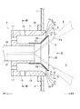
ここで、バーナ室13に導入された空気を燃焼室5側へ案内するコーン型の空気ガイド25が圧力噴射弁19の先端部を囲むように設けられ、バーナ本体11におけるバーナ室13の出口側の周縁部と空気ガイド25のテーパ部27との間に空気の流れを絞る環状の絞り部31が形成されているため、ガスタービン燃焼器1(バーナ9)の運転中に、図1に示すように、バーナ本体11におけるバーナ室13の出口側の周縁部と空気ガイド25のテーパ部27との間を通過する空気の流れに対して、径方向外側から径方向内側に向かって流速が遅くなるような流速分布を安定的に与えることができる。これにより、空気ガイド25のテーパ部27の先端部付近に径方向外側から径方向内側(空気ガイド25のテーパ部27の外側から内側)に巻くような渦Gを発生させて、換言すれば、旋回羽根を廃したシンプルな構成のバーナ9であっても、圧力噴射弁19の下流側近傍に逆流領域を形成することができる。
Here, a cone-
なお、図1中において、Va、Vb、Vc、Vd、Veは、空気の流れの流速を表しており、Va、Vb、Vc、Vd、Veの間には、Va>Vb>Vc>Vd>Veの関係が成立するようになっている。また、バーナ本体11におけるバーナ室13の出口側の周縁部と空気ガイド25のテーパ部27との間を通過する空気の流れが前述の流速分布を持つこと、及び空気ガイド25のテーパ部27の先端部付近に径方向外側から径方向内側に巻くような渦Gが発生することは、本願の発明者が非燃焼場におけるバーナ9のフロー試験によって確認してある。
In FIG. 1, Va, Vb, Vc, Vd, and Ve represent the flow velocity of the air flow, and Va> Vb> Vc> Vd> between Va, Vb, Vc, Vd, and Ve. The relationship Ve is established. Further, the flow of air passing between the peripheral edge of the
従って、本発明の実施形態によれば、旋回羽根を廃したシンプルな構成のバーナ9であっても、圧力噴射弁19の下流側近傍に逆流領域を形成できるため、圧力噴射弁19の下流側近傍の流速(局所流速)が低下して、燃料と空気の混合及び燃焼反応が維持され、火炎Fが安定することで、火炎基部Fa位置での火炎吹き消え限界領域が拡大して、バーナ9の保炎性、ガスタービン燃焼器1の燃焼安定性を高いレベルまで確保することができる。特に、空気ガイド25のテーパ部27に円形の複数の通孔29が形成されているため、空気ガイド25の複数の通孔29の出口側に渦(図示省略)を発生させることができ、前述の効果をより高めることができる。
Therefore, according to the embodiment of the present invention, the backflow region can be formed in the vicinity of the downstream side of the
なお、本発明は、前述の実施形態の説明に限るものでなく、種々の態様で実施可能である。また、本発明に包含される権利範囲は、これらの実施形態に限定されないものである。 In addition, this invention is not restricted to description of the above-mentioned embodiment, It can implement in a various aspect. Further, the scope of rights encompassed by the present invention is not limited to these embodiments.
F 火炎
Fa 火炎基部
G 渦
S 噴霧流
1 ガスタービン燃焼器
3 燃焼器ライナ
5 燃焼室
7 隔壁
9 バーナ
11 バーナ本体
13 バーナ室
15 第1空気導入孔
17 第2空気導入孔
19 圧力噴射弁
21 噴射孔
23 燃料配管
25 空気ガイド
27 テーパ部
29 通孔
31 絞り部
F flame Fa flame base G vortex
Claims (4)
内側に前記燃焼部に連通したバーナ室を有し、接線方向から前記バーナ室に空気を導入する第1空気導入孔が形成され、前記第1空気導入孔の上流側に前記バーナ室に空気を導入する第2空気導入孔が形成された筒状のバーナ本体と、
前記バーナ本体の中央部に設けられ、前記燃焼部側へ向かって燃料を噴射する燃料噴射弁と、
前記燃料噴射弁の先端部を囲むように設けられ、前記燃焼部側に向かって拡径したテーパ部を有し、前記バーナ室に導入された空気を前記燃焼部側へ案内するコーン型の空気ガイドと、を備えたことを特徴とするバーナ。 In a burner for burning a mixture of fuel and air in the combustion section to form a flame,
A burner chamber communicated with the combustion section is formed on the inner side, a first air introduction hole for introducing air into the burner chamber from a tangential direction is formed, and air is introduced into the burner chamber upstream of the first air introduction hole. A cylindrical burner body in which a second air introduction hole to be introduced is formed;
A fuel injection valve that is provided at the center of the burner body and injects fuel toward the combustion section;
Cone-type air that is provided so as to surround the tip portion of the fuel injection valve, has a tapered portion that expands toward the combustion portion, and guides the air introduced into the burner chamber to the combustion portion. A burner characterized by comprising a guide.
請求項1から請求項3のうちのいずれかのバーナを備えたことを特徴とするガスタービン燃焼器。 In a gas turbine combustor that generates a combustion gas by burning a mixture of fuel and air,
A gas turbine combustor comprising the burner according to any one of claims 1 to 3.
Priority Applications (1)
| Application Number | Priority Date | Filing Date | Title |
|---|---|---|---|
| JP2012116264A JP5991025B2 (en) | 2012-05-22 | 2012-05-22 | Burner and gas turbine combustor |
Applications Claiming Priority (1)
| Application Number | Priority Date | Filing Date | Title |
|---|---|---|---|
| JP2012116264A JP5991025B2 (en) | 2012-05-22 | 2012-05-22 | Burner and gas turbine combustor |
Publications (2)
| Publication Number | Publication Date |
|---|---|
| JP2013242101A true JP2013242101A (en) | 2013-12-05 |
| JP5991025B2 JP5991025B2 (en) | 2016-09-14 |
Family
ID=49843148
Family Applications (1)
| Application Number | Title | Priority Date | Filing Date |
|---|---|---|---|
| JP2012116264A Active JP5991025B2 (en) | 2012-05-22 | 2012-05-22 | Burner and gas turbine combustor |
Country Status (1)
| Country | Link |
|---|---|
| JP (1) | JP5991025B2 (en) |
Cited By (2)
| Publication number | Priority date | Publication date | Assignee | Title |
|---|---|---|---|---|
| JP2016133235A (en) * | 2015-01-16 | 2016-07-25 | 大阪瓦斯株式会社 | Direct advance flame type gas burner |
| KR102382600B1 (en) * | 2020-11-25 | 2022-04-06 | 한국생산기술연구원 | Combined swirl combustor |
Citations (6)
| Publication number | Priority date | Publication date | Assignee | Title |
|---|---|---|---|---|
| JPS61119919A (en) * | 1984-10-30 | 1986-06-07 | ソシエテ・ナシオナル・デテユード・エ・ドウ・コンストリユクシオン・ドウ・モトール・ダヴイアシオン、“エス.エヌ.ウ.セ.エム.アー.” | Air and fuel injector |
| JPH07260150A (en) * | 1994-03-10 | 1995-10-13 | Soc Natl Etud Constr Mot Aviat <Snecma> | Pre-mixing injection device |
| JP2007024357A (en) * | 2005-07-13 | 2007-02-01 | Hitachi Ltd | Gas turbine combustor, method of preventing carbonization of fuel, and purging method |
| JP2007033025A (en) * | 2002-08-22 | 2007-02-08 | Hitachi Ltd | Gas turbine combustor, combustion method for gas turbine combustor, and method of modifying gas turbine combustor |
| JP2007255795A (en) * | 2006-03-23 | 2007-10-04 | Ihi Corp | Burner for combustor and combustion method |
| JP2011528098A (en) * | 2008-04-11 | 2011-11-10 | ゼネラル・エレクトリック・カンパニイ | Venturi and method of manufacture |
-
2012
- 2012-05-22 JP JP2012116264A patent/JP5991025B2/en active Active
Patent Citations (6)
| Publication number | Priority date | Publication date | Assignee | Title |
|---|---|---|---|---|
| JPS61119919A (en) * | 1984-10-30 | 1986-06-07 | ソシエテ・ナシオナル・デテユード・エ・ドウ・コンストリユクシオン・ドウ・モトール・ダヴイアシオン、“エス.エヌ.ウ.セ.エム.アー.” | Air and fuel injector |
| JPH07260150A (en) * | 1994-03-10 | 1995-10-13 | Soc Natl Etud Constr Mot Aviat <Snecma> | Pre-mixing injection device |
| JP2007033025A (en) * | 2002-08-22 | 2007-02-08 | Hitachi Ltd | Gas turbine combustor, combustion method for gas turbine combustor, and method of modifying gas turbine combustor |
| JP2007024357A (en) * | 2005-07-13 | 2007-02-01 | Hitachi Ltd | Gas turbine combustor, method of preventing carbonization of fuel, and purging method |
| JP2007255795A (en) * | 2006-03-23 | 2007-10-04 | Ihi Corp | Burner for combustor and combustion method |
| JP2011528098A (en) * | 2008-04-11 | 2011-11-10 | ゼネラル・エレクトリック・カンパニイ | Venturi and method of manufacture |
Cited By (3)
| Publication number | Priority date | Publication date | Assignee | Title |
|---|---|---|---|---|
| JP2016133235A (en) * | 2015-01-16 | 2016-07-25 | 大阪瓦斯株式会社 | Direct advance flame type gas burner |
| KR102382600B1 (en) * | 2020-11-25 | 2022-04-06 | 한국생산기술연구원 | Combined swirl combustor |
| WO2022114398A1 (en) * | 2020-11-25 | 2022-06-02 | 한국생산기술연구원 | Combined swirl combustor |
Also Published As
| Publication number | Publication date |
|---|---|
| JP5991025B2 (en) | 2016-09-14 |
Similar Documents
| Publication | Publication Date | Title |
|---|---|---|
| US9518740B2 (en) | Axial swirler for a gas turbine burner | |
| EP2815184B1 (en) | Burner | |
| US20140096502A1 (en) | Burner for a gas turbine | |
| US8893500B2 (en) | Lean direct fuel injector | |
| US20080078183A1 (en) | Liquid fuel enhancement for natural gas swirl stabilized nozzle and method | |
| US20160209040A1 (en) | Gas turbine combustor and gas turbine engine equipped with same | |
| JP2009133599A (en) | Methods and systems to facilitate reducing flashback/flame holding in combustion systems | |
| RU2013108313A (en) | FUEL AIR INJECTOR (OPTIONS), COMBUSTION CAMERA FOR A GAS-TURBINE ENGINE (OPTIONS) AND METHOD OF OPERATION OF A FUEL AIR INJECTOR (OPTIONS) | |
| JP2012251742A (en) | Fuel injector | |
| JP2009052877A (en) | Gas turbine premixer with radial multistage flow path, and air-gas mixing method for gas turbine | |
| JP2009270816A (en) | Fuel nozzle for gas turbine engine, and method for manufacturing the same | |
| US8919132B2 (en) | Method of operating a gas turbine engine | |
| JP2012107855A (en) | Apparatus and method for igniting and combusting combustor | |
| EP3076077B1 (en) | Nozzle, combustion apparatus, and gas turbine | |
| JP2014215036A (en) | Can combustor for can-annular combustor arrangement in gas turbine | |
| JP2013140004A (en) | Combustor fuel nozzle and method for supplying fuel to combustor | |
| US9182124B2 (en) | Gas turbine and fuel injector for the same | |
| WO2016042787A1 (en) | Combustion burner, combustor and gas turbine | |
| JP2010181141A (en) | Burner tube of combustion system | |
| KR20180106945A (en) | Dual-fuel fuel nozzle with liquid fuel tip | |
| JP2007147125A (en) | Gas turbine combustor | |
| JP5991025B2 (en) | Burner and gas turbine combustor | |
| JP2017180906A (en) | Gas turbine combustor | |
| EP3465009B1 (en) | Fuel nozzle for a gas turbine with radial swirler and axial swirler and gas turbine | |
| JP6417620B2 (en) | Combustor, gas turbine |
Legal Events
| Date | Code | Title | Description |
|---|---|---|---|
| A621 | Written request for application examination |
Free format text: JAPANESE INTERMEDIATE CODE: A621 Effective date: 20150224 |
|
| A977 | Report on retrieval |
Free format text: JAPANESE INTERMEDIATE CODE: A971007 Effective date: 20151217 |
|
| A131 | Notification of reasons for refusal |
Free format text: JAPANESE INTERMEDIATE CODE: A131 Effective date: 20160105 |
|
| A521 | Written amendment |
Free format text: JAPANESE INTERMEDIATE CODE: A523 Effective date: 20160229 |
|
| TRDD | Decision of grant or rejection written | ||
| A01 | Written decision to grant a patent or to grant a registration (utility model) |
Free format text: JAPANESE INTERMEDIATE CODE: A01 Effective date: 20160719 |
|
| A61 | First payment of annual fees (during grant procedure) |
Free format text: JAPANESE INTERMEDIATE CODE: A61 Effective date: 20160801 |
|
| R151 | Written notification of patent or utility model registration |
Ref document number: 5991025 Country of ref document: JP Free format text: JAPANESE INTERMEDIATE CODE: R151 |
|
| R250 | Receipt of annual fees |
Free format text: JAPANESE INTERMEDIATE CODE: R250 |
|
| R250 | Receipt of annual fees |
Free format text: JAPANESE INTERMEDIATE CODE: R250 |