JP2013241089A - Vehicle front body structure - Google Patents
Vehicle front body structure Download PDFInfo
- Publication number
- JP2013241089A JP2013241089A JP2012115462A JP2012115462A JP2013241089A JP 2013241089 A JP2013241089 A JP 2013241089A JP 2012115462 A JP2012115462 A JP 2012115462A JP 2012115462 A JP2012115462 A JP 2012115462A JP 2013241089 A JP2013241089 A JP 2013241089A
- Authority
- JP
- Japan
- Prior art keywords
- vehicle body
- front side
- vehicle
- joined
- beam portion
- Prior art date
- Legal status (The legal status is an assumption and is not a legal conclusion. Google has not performed a legal analysis and makes no representation as to the accuracy of the status listed.)
- Granted
Links
- 239000000725 suspension Substances 0.000 claims abstract description 26
- 230000003014 reinforcing effect Effects 0.000 claims abstract description 18
- 239000011324 bead Substances 0.000 description 5
- 238000002485 combustion reaction Methods 0.000 description 5
- 230000005540 biological transmission Effects 0.000 description 4
- 239000011521 glass Substances 0.000 description 4
- 241001247986 Calotropis procera Species 0.000 description 2
- 238000005452 bending Methods 0.000 description 2
- 230000002452 interceptive effect Effects 0.000 description 2
- 238000012423 maintenance Methods 0.000 description 2
- 239000000463 material Substances 0.000 description 2
- 238000000034 method Methods 0.000 description 2
- 230000002787 reinforcement Effects 0.000 description 2
- 229910000831 Steel Inorganic materials 0.000 description 1
- 230000008878 coupling Effects 0.000 description 1
- 238000010168 coupling process Methods 0.000 description 1
- 238000005859 coupling reaction Methods 0.000 description 1
- 238000013016 damping Methods 0.000 description 1
- 230000000694 effects Effects 0.000 description 1
- 238000009434 installation Methods 0.000 description 1
- 239000010959 steel Substances 0.000 description 1
- 238000003466 welding Methods 0.000 description 1
Images


Landscapes
- Body Structure For Vehicles (AREA)
Abstract
Description
本発明は、自動車の車体前部構造に関し、更に詳細には、フロントサイドフレームにダンパハウジングを接合され、且つフロントサイドフレームにフロントサスペンション機構アームの支持部を含む型式の自動車の車体前部構造に関する。 The present invention relates to a vehicle body front structure of an automobile, and more particularly, to a vehicle body front structure of a type of automobile in which a damper housing is joined to a front side frame and a front side frame includes a support portion of a front suspension mechanism arm. .
自動車の車体前部構造として、車体前後方向に延在しフロントサスペンション機構アーム(ロアアーム)の支持部を含む左右のフロントサイドフレームと、前記左右のフロントサイドフレームの各々の車幅方向外側に接合されてフロントサスペンション機構用ダンパを収容する左右のダンパハウジングと、前記左右のフロントサイドフレームに接合されて車体前方のエンジンルームと当該エンジンルームより車体後方の車室とを区切るダッシュボードパネルとを有する構造のものがある。 As a vehicle body front structure, the left and right front side frames that extend in the longitudinal direction of the vehicle body and include the support portions of the front suspension mechanism arms (lower arms), and the left and right front side frames are joined to the outside in the vehicle width direction. And a left and right damper housing for housing the front suspension mechanism damper, and a dashboard panel that is joined to the left and right front side frames and separates the engine room in front of the vehicle body and the vehicle compartment in the rear of the vehicle body from the engine room. There are things.
このような構成の車体前部構造では、フロントサスペンション機構のロアアームをその機構支持部材を介して、フロントサイドフレームが支持する構造となっている。そのため、車両の走行振動が主にフロントサイドフレームから車体に入力され、フロントサイドフレームはその振動によって加振される。フロントサイドフレームの振動は、フレームと接合されている部材、特に、ダッシュボードアッパメンバ(カウルトップメンバ)の下方に存在するダッシュボードロアパネルに伝わり、更にはフロアパネルやフロントウィンドシールドガラス等の面状部材に伝わり、それら面部材が振動することによって、ロードノイズと呼ばれる車室内騒音を発生させる。 In the vehicle body front structure having such a configuration, the front side frame supports the lower arm of the front suspension mechanism via the mechanism support member. Therefore, traveling vibration of the vehicle is mainly input from the front side frame to the vehicle body, and the front side frame is vibrated by the vibration. The vibration of the front side frame is transmitted to the members joined to the frame, especially the dashboard lower panel below the dashboard upper member (cowl top member), and also the surface shape of the floor panel, front windshield glass, etc. When the surface members are transmitted to the members and vibrate, the vehicle interior noise called road noise is generated.
特に荒れた路面を走行する際には、フロントサイドフレームに、上下、左右、前後方向の振動が入力され、なかでも低中周波(約100〜500ヘルツ)の振動が入力されことにより、乗員に不快感を与える騒音が車室内に発生するため、これを抑制することが商品性を向上させる上で課題となっている。 Especially when driving on rough roads, vibrations in the top, bottom, left and right and front and rear directions are input to the front side frame, especially low and medium frequency (about 100 to 500 Hz) vibrations. Since the noise which gives an unpleasant feeling generate | occur | produces in a vehicle interior, it has become a subject when improving this, suppressing this.
このような車両走行時の車室内騒音を低減するために、カウルトップメンバの車幅方向端部を接合されるホイールハウスアッパメンバやフロントピラー等の車体側部メンバに近い部位に、弾性的な屈曲点となるビードを設ける技術が知られている(例えば、特許文献1)。 In order to reduce such vehicle interior noise when the vehicle is running, elastically close to the vehicle side member such as the wheel house upper member and the front pillar joined to the end of the cowl top member in the vehicle width direction. A technique for providing a bead serving as a bending point is known (for example, Patent Document 1).
この技術では、車体側部メンバからカウルトップメンバに振動が伝達されることをビードの弾性的な屈曲によって抑制することで、車体側部メンバからカウルトップメンバを介してダッシュボードパネルに伝達される振動を抑制することができる。 In this technique, vibration is transmitted from the vehicle body side member to the cowl top member by suppressing the elastic bending of the bead and transmitted from the vehicle body side member to the dashboard panel via the cowl top member. Vibration can be suppressed.
しかしながら、上述のような従来技術では、ビードによりカウルトップメンバを含む特定の振動伝達経路上の振動の伝達を遮断することはできるが、ダッシュボードパネルには、車体側部に配置されたホイールハウスアッパメンバの他にフロントサイドフレームなどからも振動が入力され、このようなビードを経由しない振動伝達経路については振動の伝達を遮断することはできない。もっとも、フロントサスペンション機構から車体への振動入力そのものを遮断することはできない。 However, in the related art as described above, transmission of vibration on a specific vibration transmission path including the cowl top member can be blocked by the bead, but the dashboard panel has a wheel house disposed on the side of the vehicle body. In addition to the upper member, vibration is also input from the front side frame and the like, and vibration transmission cannot be interrupted for such a vibration transmission path that does not pass through the bead. However, the vibration input itself from the front suspension mechanism to the vehicle body cannot be blocked.
また、ビードを設けても、鋼板製のカウルトップメンバが車体側部メンバに接続された状態に変わりはなく、特定の周波数を除いて振動エネルギが伝達することに変わりはないため、車室内騒音を十分に低減することができない。 In addition, even if a bead is provided, the state where the steel plate cowl top member is connected to the vehicle body side member remains unchanged, and vibration energy is transmitted except for a specific frequency. Cannot be reduced sufficiently.
本発明が解決しようとする課題は、本発明が解決しようとする課題は、フロントサイドフレームをはじめとするフロントサスペンション機構支持部から車体に入力された、走行振動に起因して発生する不快な車室内騒音(ロードノイズ)を低減することである。 The problem to be solved by the present invention is that the problem to be solved by the present invention is that an uncomfortable vehicle caused by running vibration input to the vehicle body from the front suspension mechanism support part including the front side frame. It is to reduce indoor noise (road noise).
本発明による自動車の車体前部構造は、車体前後方向に延在しフロントサスペンション機構のアーム(46)の支持部を含む左右のフロントサイドフレーム(10)と、前記左右のフロントサイドフレーム(10)の各々に接合されてフロントサスペンション機構用ダンパ(54)を収容する左右のダンパハウジング(26)と、前記左右のフロントサイドフレーム(10)に接合されて車体前側のエンジンルーム(22)と当該エンジンルーム(22)より車体後側の車室(24)とを区切るダッシュボードパネル(20、98)とを有する自動車の車体前部構造であって、左右の脚部(72)と、車体幅方向に延在して前記左右の脚部(72)の上部を互いに繋ぐ横梁部(74)と、前記脚部(72)と前記横梁部(74)をトラス構造で繋ぐ左右の傾斜支持部(88)とを具備した門形補強部材(70)を有し、前記左右の脚部(72)は、各々、下端部を前記フロントサスペンション機構のアーム(46)の前記支持部近傍において前記左右のフロントサイドフレーム(10)に接合され、且つ前記左右のダンパハウジング(26)の前記エンジンルーム(22)側の壁面に沿って上下に延在して当該壁面に接合されている。 The vehicle body front structure according to the present invention includes left and right front side frames (10) extending in the longitudinal direction of the vehicle body and including support portions of arms (46) of a front suspension mechanism, and the left and right front side frames (10). The left and right damper housings (26) for receiving the front suspension mechanism damper (54) and the left and right front side frames (10) and the engine room (22) on the front side of the vehicle body and the engine A vehicle body front structure having a dashboard panel (20, 98) separating a vehicle compartment (24) on the rear side of the vehicle body from a room (22), the left and right leg portions (72), and the vehicle body width direction A truss structure with a cross beam portion (74) connecting the upper portions of the left and right leg portions (72) to each other, and the leg portion (72) and the cross beam portion (74). The left and right leg portions (72) each have a lower end portion of the arm (46) of the front suspension mechanism. In the vicinity of the support portion, it is joined to the left and right front side frames (10), and extends vertically along the wall surface of the left and right damper housing (26) on the engine room (22) side and joined to the wall surface. ing.
この構成によれば、上述した車体前部構造の剛性が高くなる。これにより、車両が荒い路面を走行した時にサスペンションアームから車体側に入力される振動エネルギを低減すると同時に、フロントサイドフレーム(10)が上下、左右、前後方向に振動することが抑制され、ダッシュボードパネル(20、98)やフロアパネル、フロントウィンドシールドガラスなどの面状部材に伝達する振動が低減し、それら面状部材の振動を抑制することができるので、車室内に発生する不快な騒音である低中周波ロードノイズが低減する。 According to this configuration, the rigidity of the vehicle body front structure described above is increased. As a result, when the vehicle travels on a rough road surface, vibration energy input from the suspension arm to the vehicle body side is reduced, and at the same time, the front side frame (10) is suppressed from vibrating in the vertical, horizontal, and front-rear directions. The vibration transmitted to the planar members such as the panels (20, 98), the floor panel, and the front windshield glass can be reduced and the vibrations of these planar members can be suppressed. Certain low and medium frequency road noise is reduced.
本発明による自動車の車体前部構造は、好ましくは、前記横梁部(74)は矩形閉断面形状をなし、前記脚部(72)はコ字形断面形状をしていて前記ダンパハウジング(26)の前記壁面と協働として矩形閉断面形状をなしている。 In the vehicle body front structure according to the present invention, preferably, the transverse beam portion (74) has a rectangular closed cross-sectional shape, and the leg portion (72) has a U-shaped cross-sectional shape so that the damper housing (26) A rectangular closed cross-sectional shape is formed in cooperation with the wall surface.
この構成によれば、門形補強部材(70)は高剛性の補強部材になり、ダンパ
ハウジング(26)を含む車体前部の剛性を高めることができるので、フロン
トサスペンション機構の支持剛性が向上し、振動伝達を抑制すると同時に車両
の操縦安定性が向上する。
According to this configuration, the portal reinforcing member (70) becomes a highly rigid reinforcing member, and the rigidity of the front portion of the vehicle body including the damper housing (26) can be increased, so that the support rigidity of the front suspension mechanism is improved. In addition, vibration control is suppressed, and at the same time, vehicle handling stability is improved.
本発明による自動車の車体前部構造は、好ましくは前記横梁部(74)が前記ダッシュボードパネル(20、98)に固定されている。 In the vehicle body front part structure according to the present invention, the transverse beam part (74) is preferably fixed to the dashboard panel (20, 98).
この構成によれば、ダッシュボードパネル(20、98)の支持剛性が増し、ダッシュボードパネル(20、98)が振動し難くなる。このことによっても低中周波ロードノイズが低減する。 According to this configuration, the support rigidity of the dashboard panel (20, 98) is increased, and the dashboard panel (20, 98) is less likely to vibrate. This also reduces low and medium frequency road noise.
本発明による自動車の車体前部構造は、好ましくは、前記横梁部の下縁に沿って延在して当該横梁部に固定された連結部材を更に有し、当該連結部材に前記傾斜支持部の上部が固定され、前記傾斜支持部は前記連結部材を介して前記横梁部に固定されており、前記横梁部は前記連結部材を介して前記ダッシュボードパネルに固定されている。 The vehicle body front structure according to the present invention preferably further includes a connecting member extending along a lower edge of the horizontal beam portion and fixed to the horizontal beam portion, and the inclined support portion of the inclined support portion is connected to the connecting member. The upper part is fixed, the inclined support part is fixed to the transverse beam part via the connecting member, and the transverse beam part is fixed to the dashboard panel via the connecting member.
この構成によれば、傾斜支持部材(88)が,門型補強部材(70)をさらに補強する筋交いとしての機能を発揮し、ダンパハウジング(26)を含む車体前部の剛性、ならびにダッシュボードパネル(20、98)の支持剛性も効果的に向上する。よって,低中周波ロードノイズの低減ならびに操縦安定性の向上に効果を発揮する。 According to this configuration, the inclined support member (88) functions as a brace that further reinforces the portal reinforcing member (70), the rigidity of the vehicle body including the damper housing (26), and the dashboard panel. The support rigidity of (20, 98) is also effectively improved. Therefore, it is effective in reducing low and medium frequency road noise and improving steering stability.
本発明による自動車の車体前部構造は、好ましくは、更に、前記左右のフロントサイドフレーム(10)の下方を車体前後方向に延在する左右2個の縦メンバ(32)と車幅方向に延在して前記縦メンバ(32)の前端部同士と後端部あるいは後端部近傍同士とを各々繋ぐ前後2個の横メンバ(34、36)とにより平面視で略矩形状に構成されたサブフレーム(30)を有し、前記サブフレーム(30)は、フロントサスペンション機構のロアアーム(46)を支持し、前記門形補強部材(70)の前記脚部(72)と前記フロントサイドフレーム(10)との接合部の下方に前記フロントサイドフレームに対する接合部を有する。 The vehicle body front structure according to the present invention preferably further extends in the vehicle width direction with two left and right vertical members (32) extending in the vehicle longitudinal direction below the left and right front side frames (10). The vertical members (32) are formed in a substantially rectangular shape in plan view by the two front and rear horizontal members (34, 36) that connect the front ends of the vertical members (32) and the rear ends or the vicinity of the rear ends. The subframe (30) supports a lower arm (46) of a front suspension mechanism, and the leg (72) of the portal-shaped reinforcing member (70) and the front side frame (30) have a subframe (30). 10) and a joint portion to the front side frame is provided below the joint portion.
この構成によれば、サブフレーム(30)を有する車体前部構造において、門型部材(70)の効果により、サスペンション機構を支持するサブフレームを車体へ取り付けた状態での車体前部の剛性を向上させることができるため、低中周波ロードノイズの低減ならびに操縦安定性の向上を図ることができる。 According to this configuration, in the vehicle body front portion structure having the subframe (30), the rigidity of the vehicle body front portion with the subframe supporting the suspension mechanism attached to the vehicle body is increased by the effect of the gate-shaped member (70). Therefore, it is possible to reduce low and medium frequency road noise and improve steering stability.
本発明による自動車の車体前部構造は、好ましくは、前記傾斜支持部(88)は、前記脚部(72)より車体後方にオフセット配置されている。 In the vehicle body front structure according to the present invention, preferably, the inclined support portion (88) is offset from the leg portion (72) at the rear of the vehicle body.
この構成によれば、エンジンルーム(22)に配置される内燃機関(110)の吸気管(112)等に傾斜支持部(88)が干渉することを避けることができ、車体前部の小型化を図ることができる。 According to this configuration, the inclined support portion (88) can be prevented from interfering with the intake pipe (112) of the internal combustion engine (110) disposed in the engine room (22), and the vehicle body front portion can be reduced in size. Can be achieved.
本発明による自動車の車体前部構造は、好ましくは、前記門形補強部材(70)の上部にダッシュボードアッパリッド(100)が着脱可能に連結されている。 In the vehicle body front part structure according to the present invention, preferably, a dashboard applique (100) is detachably connected to an upper portion of the portal reinforcing member (70).
この構成によれば、内燃機関(110)やエンジンルーム(22)のダッシュボードパネル(20、98)側にある機器のメンテナンスのためのアクセスが容易になる。また、ダッシュボードパネル(20、98)を前方に配置し、エンジンルーム(22)を小型化できるため、その分、車室内空間を拡大できる。 According to this structure, the access for the maintenance of the apparatus in the dashboard panel (20, 98) side of an internal combustion engine (110) or an engine room (22) becomes easy. Moreover, since the dashboard panel (20, 98) is disposed in front and the engine room (22) can be reduced in size, the interior space of the vehicle can be expanded accordingly.
本発明による自動車の車体前部構造によれば、門形補強部材の設置によってフロントサイドフレームおよびダンパハウジングで構成されるサスペンション機構支持部の剛性、ならびに、車体前部の剛性が高くなり、車両が荒い路面を走行した時にサスペンションアームから車体側に入力される振動エネルギを低減すると同時に、フロントサイドフレームが上下、左右、前後方向に振動することが抑制され、ダッシュボードパネルやフロアパネル、フロントウィンドシールドガラスなどの面状部材に伝達する振動が低減し、それら面状部材の振動を抑制することができるので、車室内に発生する不快な騒音である低中周波ロードノイズが低減する。また横梁部がダッシュボードパネルに固定されていることにより、ダッシュボードパネルの支持剛性が増し、ダッシュボードパネルが振動し難くなることによっても低中周波ロードノイズが低減する。 According to the vehicle body front structure according to the present invention, the rigidity of the suspension mechanism support portion composed of the front side frame and the damper housing and the rigidity of the vehicle body front portion are increased by the installation of the gate-shaped reinforcing member. When driving on rough roads, vibration energy input from the suspension arm to the vehicle body side is reduced, and at the same time, the front side frame is prevented from vibrating in the vertical, horizontal, and front-rear directions. Since vibrations transmitted to planar members such as glass are reduced and vibrations of these planar members can be suppressed, low and medium frequency road noise, which is an unpleasant noise generated in the passenger compartment, is reduced. In addition, since the horizontal beam portion is fixed to the dashboard panel, the support rigidity of the dashboard panel is increased, and the dashboard panel is less likely to vibrate, thereby reducing low and medium frequency road noise.
以下に、本発明による自動車の車体前部構造の一つの実施形態を、図1〜図5を参照して説明する。 Hereinafter, an embodiment of a vehicle body front structure according to the present invention will be described with reference to FIGS.
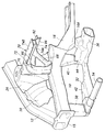
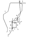
本実施形態における車両の前部構造の斜視図を図1に、その断面図を図2に示す。自動車の車体前部は、骨格部材として、車体前部の車幅方向両側を車体前後方向に延在する左右のフロントサイドフレーム10と、フロントサイドフレーム10の車幅方向外側にあって図示されていない左右のフロントピラーから前下がりに前方へ延出する左右のホイールハウスアッパメンバ(アッパメンバ+ロアパメンバ)12とを有する。
FIG. 1 is a perspective view of a front structure of a vehicle in the present embodiment, and FIG. 2 is a sectional view thereof. The front part of the vehicle body is shown as a skeletal member on the left and right front side frames 10 extending in the vehicle longitudinal direction on both sides in the vehicle width direction of the front part of the vehicle body, and on the outside in the vehicle width direction of the
左右のフロントサイドフレーム10の前端部と左右のホイールハウスアッパメンバ12の前端部(下端部)とは、左右のもの同士を互い連結する連結プレート(ガセット)15が接合されている。左右のフロントサイドフレーム10の後端部には車体前後方向に延在する左右のフロントフロアフレーム16が接合されている。左右のホイールハウスアッパメンバ12の上端部は車幅方向に延在するウィンドシールドロアサポートパネル18の左右の端部が接合されている。これにより、ウィンドシールドロアサポートパネル18は左右のホイールハウスアッパメンバ12の上端部を互いに連結している。
The front end portions of the left and right front side frames 10 and the front end portions (lower end portions) of the left and right wheel house
ウィンドシールドロアサポートパネル18の下側にはダッシュボードロアパネル20が接合されている。ダッシュボードロアパネル20は、左右両側の下部を左右のフロントサイドフレーム10の後端部近傍に接合され、車体前側のエンジンルーム22と当該エンジンルーム22より車体後側の車室24とを区切っている。換言すると、エンジンルーム22の車体後側と車室24の車体前側とはダッシュボードロアパネル20によって画定されている。ダッシュボードロアパネル20の上部にはウィンドシールドロアサポートパネル18と共にダッシュボードアッパパネル(フロントカウルトップメンバ)98(図4参照)が接合されている。
A dashboard
エンジンルーム22の左右両側には各々フロントサイドフレーム10の外側面とホイールハウスアッパメンバ12の内側面とダッシュボードロアパネル20の左右の側縁とに接合された左右のダンパハウジング26が設けられている。更に、左右のダンパハウジング26の車体前側には各々フロントサイドフレーム10の外側面とホイールハウスアッパメンバ12の内側面とダンパハウジング26の前縁とに接合された左右のフロントタイヤハウスメンバ28が連続して設けられている。
Left and
エンジンルーム22の下部にはフロントサブフレーム30が配置されている。フロントサブフレーム30は、左右のフロントサイドフレーム10の下方を車体前後方向に延在する左右2個の縦メンバ32と、車幅方向に延在して縦メンバ32の前端部同士を互いに繋ぐ前部横メンバ34及び縦メンバ32の後端近傍部同士を互いに繋ぐ後部横メンバ36とにより平面視で略矩形状に構成されている。本実施形態では、縦メンバ32と後部横メンバ36とは矩形閉断面形状材により構成され、前部横メンバ34はパイプ材により構成されている。
A
左右のフロントサイドフレーム10の前端下部と後端近傍下部には各々矩形閉断面形状による前側マウントメンバ38と後側マウントメンバ40の上端が接合されている。前側マウントメンバ38と後側マウントメンバ40とは各々フロントサイドフレーム10より垂下している。左右の前側マウントメンバ38の下端には縦メンバ32の前端部が接合されている。左右の後側マウントメンバ40の下端には後部横メンバ36の左右の端部が接合されている。更に、左右の縦メンバ32の後端部はフロントフロアフレーム16の前端近傍の底部に形成された後側マウント部16A(図2参照)に接合されている。このようにしてフロントサブフレーム30は、左右のフロントサイドフレーム10とは左右のフロントフロアフレーム16の下部に吊り下げ式に固定配置されている。
The upper ends of the
左右の縦メンバ32の前端近傍部には前側アーム支持部42が、後部横メンバ36の左右の端部には後側アーム支持部44が各々形成されている。左右の前側アーム支持部42は各々フロントサスペンション機構のトリポート形(A型)のロアアーム46の前アーム部46Aをゴムブシュ(図示省略)を介して枢軸48によって支持している。左右の後側アーム支持部44は各々ロアアーム46の後アーム部46Bをゴムブシュ(図示省略)を介して枢軸50によって支持している。
A front
ロアアーム46の中間アーム部46Cはナックルアーム52の下部を上下方向の軸線周りに回動可能に支持している。ナックルアーム52は、ナックル支持部52Aと、タイロッド連結部52Bと、ブレーキキャリパ支持部52Cとを有する。
The intermediate arm portion 46C of the
フロントサスペンション機構は、ストラッド型のものであり、左右のダンパハウジング26には、各々、所要の減衰力を発生するダンパ装置54と、ダンパ装置54を伸長方向に付勢するコイルばね56とが配置されている。左右のダンパ装置54は各々上端部をダンパハウジング26の上壁部に連結部58によって連結され、下端部を連結部60によってナックルアーム52に可動連結されている。
The front suspension mechanism is of a straddle type, and the left and
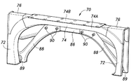
ダッシュボードロアパネル20の前方には門形補強部材70が配置されている。門形補強部材70は、図5に示されているように、左右の脚部72と、車体幅方向に延在して左右の脚部72の上端部を互いに繋ぐ横梁部74とを有し、脚部72の上部側が湾曲していることにより全体でアーチ状をなしている。更に、左右の脚部72の湾曲形状部分には、各々脚部72の略鉛直な外側部と横梁部74の略水平な上部とを直角で結ぶ略三角形状の隅角部補填部材76が接合されている。
A
左右の脚部72は、各々下端部をロアアーム46の支持部近傍、つまり、後側マウントメンバ40の配置部の上部においてフロントサイドフレーム10に接合されている。左右の脚部72と隅角部補填部材76とはダンパハウジング26のエンジンルーム22側の壁面に沿って上下に延在し、当該壁面に接合されている。脚部72と隅角部補填部材76とは各々コ字形断面形状でしていてダンパハウジング26の壁面と協働として矩形閉断面形状をなしている。横梁部74は、上部開口の横転コ字形断面形状の本体74Aと、本体74Aの上部開口を閉じるように本体74Aにボルト78とナット80(図4参照)とによって締結固定された帯板形状の蓋体74Bとにより矩形閉断面形状をなしている。
The left and
脚部72の上側部分と横梁部74の車体後方側の外壁には、これらの下縁に沿って延在してこれらにボルト82とナット84(図4参照)とによって板状の連結部材86が取り付けられている。
The upper part of the
左右の脚部72の車体後方側の下端部近傍には各々板状の傾斜支持部材88の下端部がボルト89によって固定されている。左右の傾斜支持部材88は各々上端部をボルト90によって連結部材86の車幅方向の中央近傍に固定されている。これにより、傾斜支持部材88は、脚部72と横梁部74とを連結部材86を介してトラス構造で繋いでおり、筋交いとしての機能を十分に発揮できる。
In the vicinity of the lower end of the left and
連結部材86の車幅方向中央部(左右の傾斜支持部材88の間)にはブラケット片92の一端が接合されている。ブラケット片92の他端はボルト94、96によってダッシュボードアッパパネル98に固定されている。これにより、横梁部74は車幅方向中央部を連結部材86およびブラケット片92を介してダッシュボードアッパパネル98の前端部に固定される。
One end of the
門形補強部材70は傾斜支持部材88を含んでトラス構造をなしているから、高剛性の補強部材をなす。更に、脚部72と隅角部補填部材76とは各々コ字形断面形状でしていてダンパハウジング26の壁面と協働として矩形閉断面形状をなし、横梁部74は本体74Aと蓋体74Bとにより矩形閉断面形状をなしていることにより、門形補強部材70は高剛性の補強部材をなす。
Since the
フロントサイドフレーム10の後側マウントメンバ40の配置部の上部に、つまりフロントサイドフレーム10に対するロアアーム46よりの走行振動の入力部に高剛性構造の門形補強部材70の脚部72の下端部が接合されていることにより、サスペンション機構を支持する車体前部の剛性ならびにフロントサイドフレーム10に対する走行振動入力部の剛性が高くなる。これにより、車両が荒い路面を走行した時にサスペンションアームから車体側に入力される振動エネルギを低減すると同時に、フロントサイドフレーム10が上下、左右、前後方向に振動することが抑制され、ダッシュボードロアパネル20や図示されていないフロアパネル、フロントウィンドシールドガラスなどの面状部材に伝達する振動が低減し、それら面状部材の振動を抑制することができるので、車室内に発生する不快な騒音である低中周波ロードノイズが低減する。
The lower end portion of the
また、横梁部74が連結部材86を介してブラケット片92によってダッシュボードアッパパネル98に固定されていることにより、ダッシュボードアッパパネル98の支持剛性も増し、ダッシュボードアッパパネル98が振動し難くなる。このことによっても低中周波ロードノイズが低減する。
Further, since the
また、脚部72がダンパハウジング26の壁面と接合されて矩形閉断面形状をなすことにより、ダンパハウジング26を含む車体前部の剛性を高めることができるので、フロントサスペンション機構の支持剛性が向上し、振動伝達を抑制すると同時に車両の操縦安定性が向上する。
Further, since the
本実施形態では、連結部材86および傾斜支持部材88の前面は、連結部材86および傾斜支持部材88が横梁部74および脚部72の車体後方側に設けられていることにより、横梁部74および脚部72の車体前後方向の寸法分、横梁部74および脚部72の前面より車体後方にオフセットされた位置にある。
In this embodiment, the front surfaces of the connecting
これにより、図3に示されているように、エンジンルーム22に配置される内燃機関110の吸気管112等に連結部材86および傾斜支持部材88が干渉することを避けることができ、車体前部の小型化を図ることができる。
As a result, as shown in FIG. 3, it is possible to avoid the
横梁部74の蓋体74Bの上部には、図4に示されているように、ダッシュボードアッパリッド100がボルト78とナット80とによって蓋体74Bと共に横梁部74の本体74Aに着脱可能に固定されている。ダッシュボードアッパリッド100の後端部は、ボルト94とナット96とによってブラケット片92と共にダッシュボードアッパパネル98の前端部に着脱可能に固定されている。
As shown in FIG. 4, the dashboard upper 100 is detachably fixed to the
ダッシュボードアッパリッド100が取り外し可能であることにより、内燃機関110やエンジンルーム22のダッシュボードロアパネル20側にある機器のメンテナンスのためのアクセスが容易になる。また、ダッシュボードアッパパネル98を前方に配置してエンジンルーム22を小型化できるため、その分、車室内空間を拡大できる。
Since the
以上、本発明を、その好適形態実施例について説明したが、本発明はこのような実施例により限定されるものではなく、本発明の趣旨を逸脱しない範囲で適宜変更可能である。例えば、連結部材86、傾斜支持部材88等の取り付けは、ボルト締結に代えて溶接によって行われてもよい。フロントサブフレーム30の後部横メンバ36は縦メンバ32の後端部同士を互いに繋ぐ構成でもよい。また、上記実施形態に示した構成要素は必ずしも全てが必須なものではなく、本発明の趣旨を逸脱しない限りにおいて適宜取捨選択することが可能である。例えば、連結部材86が省略されてもよい。この場合には、傾斜支持部材88の上端部は横梁部74に直接固定され、横梁部74はブラケット片92と同等のものでダッシュボードアッパパネル98に直接固定される。フロントサブフレーム30は必須でなく、フロントサブフレーム30を有さない場合には、ロアアーム46はフロントサイドフレーム10に直接取り付けられればよい。
Although the present invention has been described with reference to the preferred embodiment, the present invention is not limited to such an embodiment, and can be changed as appropriate without departing from the spirit of the present invention. For example, attachment of the connecting
10 フロントサイドフレーム
12 ホイールハウスアッパメンバ
16 フロントフロアフレーム
18 ウィンドシールドロアサポートパネル
20 ダッシュボードロアパネル
22 エンジンルーム
24 車室
26 ダンパハウジング
28 フロントタイヤハウスメンバ
30 フロントサブフレーム
32 縦メンバ
34 前部横メンバ
36 後部横メンバ
46 ロアアーム
52 ナックルアーム
54 ダンパ装置
56 コイルばね
70 門形補強部材
72 脚部
74 横梁部
76 隅角部補填部材
86 連結部材
88 傾斜支持部材
98 ダッシュボードアッパパネル
100 ダッシュボードアッパリッド
110 内燃機関
112 吸気管
DESCRIPTION OF
特に荒れた路面を走行する際には、フロントサイドフレームに、上下、左右、前後方向の振動が入力され、なかでも低中周波(約100〜500ヘルツ)の振動が入力されることにより、乗員に不快感を与える騒音が車室内に発生するため、これを抑制することが商品性を向上させる上で課題となっている。 When riding, especially rough road surface, the front side frames, upper and lower, left and right, are inputted vibration in the longitudinal direction, among others by the vibration of the low-medium-frequency (approximately 100 to 500 hertz) of are entered, the occupant Since noise that causes discomfort is generated in the passenger compartment, it is a challenge to improve the merchantability.
Claims (7)
左右の脚部と、車体幅方向に延在して前記左右の脚部の上部を互いに繋ぐ横梁部と、前記脚部と前記横梁部をトラス構造で繋ぐ左右の傾斜支持部とを具備した門形補強部材を有し、
前記左右の脚部は、各々、下端部を前記フロントサスペンション機構のアームの前記支持部近傍において前記左右のフロントサイドフレームに接合され、且つ前記左右のダンパハウジングの前記エンジンルーム側の壁面に沿って上下に延在して当該壁面に接合されている自動車の車体前部構造。 Left and right front side frames extending in the longitudinal direction of the vehicle body and including a support portion of a front suspension mechanism arm; left and right damper housings joined to each of the left and right front side frames to accommodate a damper for a front suspension mechanism; A vehicle body front structure having an engine room on the front side of the vehicle body and a dashboard panel that separates a vehicle room on the rear side of the vehicle body from the engine room, joined to the left and right front side frames,
A gate comprising left and right leg portions, a horizontal beam portion extending in the vehicle body width direction and connecting the upper portions of the left and right leg portions to each other, and a left and right inclined support portion connecting the leg portions and the horizontal beam portion with a truss structure Having a shape reinforcing member,
The left and right legs are joined at their lower ends to the left and right front side frames in the vicinity of the support portion of the arm of the front suspension mechanism, and along the engine room side wall surface of the left and right damper housings. A vehicle body front structure that extends vertically and is joined to the wall surface.
Priority Applications (1)
| Application Number | Priority Date | Filing Date | Title |
|---|---|---|---|
| JP2012115462A JP5872961B2 (en) | 2012-05-21 | 2012-05-21 | Auto body front structure |
Applications Claiming Priority (1)
| Application Number | Priority Date | Filing Date | Title |
|---|---|---|---|
| JP2012115462A JP5872961B2 (en) | 2012-05-21 | 2012-05-21 | Auto body front structure |
Publications (2)
| Publication Number | Publication Date |
|---|---|
| JP2013241089A true JP2013241089A (en) | 2013-12-05 |
| JP5872961B2 JP5872961B2 (en) | 2016-03-01 |
Family
ID=49842448
Family Applications (1)
| Application Number | Title | Priority Date | Filing Date |
|---|---|---|---|
| JP2012115462A Expired - Fee Related JP5872961B2 (en) | 2012-05-21 | 2012-05-21 | Auto body front structure |
Country Status (1)
| Country | Link |
|---|---|
| JP (1) | JP5872961B2 (en) |
Cited By (2)
| Publication number | Priority date | Publication date | Assignee | Title |
|---|---|---|---|---|
| KR101786657B1 (en) * | 2013-12-17 | 2017-10-18 | 현대자동차주식회사 | Structure for connecting front vehicle body |
| US10232881B2 (en) | 2015-06-25 | 2019-03-19 | Honda Motor Co., Ltd. | Vehicle body front structure |
Citations (4)
| Publication number | Priority date | Publication date | Assignee | Title |
|---|---|---|---|---|
| JPS6447484U (en) * | 1987-09-18 | 1989-03-23 | ||
| JPH02136777U (en) * | 1989-04-20 | 1990-11-14 | ||
| JP2006213291A (en) * | 2005-02-07 | 2006-08-17 | Honda Motor Co Ltd | Vehicle front structure |
| JP2008126927A (en) * | 2006-11-24 | 2008-06-05 | Mazda Motor Corp | Front body structure of vehicle |
-
2012
- 2012-05-21 JP JP2012115462A patent/JP5872961B2/en not_active Expired - Fee Related
Patent Citations (4)
| Publication number | Priority date | Publication date | Assignee | Title |
|---|---|---|---|---|
| JPS6447484U (en) * | 1987-09-18 | 1989-03-23 | ||
| JPH02136777U (en) * | 1989-04-20 | 1990-11-14 | ||
| JP2006213291A (en) * | 2005-02-07 | 2006-08-17 | Honda Motor Co Ltd | Vehicle front structure |
| JP2008126927A (en) * | 2006-11-24 | 2008-06-05 | Mazda Motor Corp | Front body structure of vehicle |
Cited By (2)
| Publication number | Priority date | Publication date | Assignee | Title |
|---|---|---|---|---|
| KR101786657B1 (en) * | 2013-12-17 | 2017-10-18 | 현대자동차주식회사 | Structure for connecting front vehicle body |
| US10232881B2 (en) | 2015-06-25 | 2019-03-19 | Honda Motor Co., Ltd. | Vehicle body front structure |
Also Published As
| Publication number | Publication date |
|---|---|
| JP5872961B2 (en) | 2016-03-01 |
Similar Documents
| Publication | Publication Date | Title |
|---|---|---|
| JP5541133B2 (en) | Motor mount structure for electric vehicles | |
| WO2013094190A1 (en) | Front sub-frame structure for automobiles | |
| JP5872962B2 (en) | Auto body front structure | |
| KR101705146B1 (en) | Structure of subframe for vehicle | |
| WO2013108353A1 (en) | Structure for front section of vehicle body | |
| CN203864796U (en) | Front auxiliary frame assembly | |
| JP6511885B2 (en) | Automotive front structure | |
| JP2012140055A (en) | Motor mount structure of electric vehicle | |
| JP6668743B2 (en) | Body structure | |
| CN105882759A (en) | Upper vehicle-body structure of vehicle | |
| JP2016049786A (en) | Vehicle body front structure | |
| JP2010158949A (en) | Rear mount structure of engine | |
| JP2013129221A (en) | Front subframe structure of vehicle | |
| US20180265131A1 (en) | Rear subframe structure | |
| JP2008260331A (en) | Front part structure for automobile | |
| WO2019082829A1 (en) | Work vehicle | |
| JP2004276698A (en) | Front vehicle body structure of vehicle | |
| JP2019217889A (en) | Rear vehicle body structure for vehicle | |
| JP2014151657A (en) | Vehicular front body structure | |
| WO2016076046A1 (en) | Front structure of vehicle body | |
| JP5872961B2 (en) | Auto body front structure | |
| JP5622045B2 (en) | Powertrain support device | |
| JP2014101014A (en) | Understructure of vehicle | |
| JP2010280237A (en) | Front lower part structure for vehicle | |
| JP2013241041A (en) | Vehicle front body structure |
Legal Events
| Date | Code | Title | Description |
|---|---|---|---|
| A621 | Written request for application examination |
Free format text: JAPANESE INTERMEDIATE CODE: A621 Effective date: 20141128 |
|
| A977 | Report on retrieval |
Free format text: JAPANESE INTERMEDIATE CODE: A971007 Effective date: 20150928 |
|
| A131 | Notification of reasons for refusal |
Free format text: JAPANESE INTERMEDIATE CODE: A131 Effective date: 20150929 |
|
| A521 | Request for written amendment filed |
Free format text: JAPANESE INTERMEDIATE CODE: A523 Effective date: 20151006 |
|
| TRDD | Decision of grant or rejection written | ||
| A01 | Written decision to grant a patent or to grant a registration (utility model) |
Free format text: JAPANESE INTERMEDIATE CODE: A01 Effective date: 20151222 |
|
| A61 | First payment of annual fees (during grant procedure) |
Free format text: JAPANESE INTERMEDIATE CODE: A61 Effective date: 20160114 |
|
| R150 | Certificate of patent or registration of utility model |
Ref document number: 5872961 Country of ref document: JP Free format text: JAPANESE INTERMEDIATE CODE: R150 |
|
| LAPS | Cancellation because of no payment of annual fees |