JP2013236995A - Air current generating device - Google Patents
Air current generating device Download PDFInfo
- Publication number
- JP2013236995A JP2013236995A JP2012110542A JP2012110542A JP2013236995A JP 2013236995 A JP2013236995 A JP 2013236995A JP 2012110542 A JP2012110542 A JP 2012110542A JP 2012110542 A JP2012110542 A JP 2012110542A JP 2013236995 A JP2013236995 A JP 2013236995A
- Authority
- JP
- Japan
- Prior art keywords
- electrode
- dielectric
- voltage
- induced flow
- generation device
- Prior art date
- Legal status (The legal status is an assumption and is not a legal conclusion. Google has not performed a legal analysis and makes no representation as to the accuracy of the status listed.)
- Pending
Links
Images

Abstract
Description
本発明の実施形態は、気流発生装置に関する。 Embodiments described herein relate generally to an airflow generation device.
流体機器や流体機器システムにおいて、省エネルギの観点から、動力の低減を図る必要がある。また、プラントの安全性確保、作業環境向上の観点から、流体機器や流体機器システムに起因する振動や騒音を抑制する必要がある。 In fluid equipment and fluid equipment systems, it is necessary to reduce power from the viewpoint of energy saving. In addition, it is necessary to suppress vibration and noise caused by fluid equipment and fluid equipment systems from the viewpoint of ensuring plant safety and improving the work environment.
上記した必要性を満たすために、流体機器や流体機器システムに、流体をプラズマ化して気流を発生させる気流発生装置を備える検討がなされている。 In order to satisfy the above-described needs, studies have been made to provide a fluid device or a fluid device system with an air flow generation device that generates a gas flow by converting the fluid into plasma.
この気流発生装置によれば、平板上に非常に薄い層状の誘起流を適宜制御しながら発生させることが可能である。この発生した誘起流により、流れの境界層の速度分布を変化させたり、層流から乱流への遷移を強制的に引き起こしたり、渦を発生または消滅させたりするなどの気流制御を実現することができる。そのため、種々の産業機器の革新的要素技術として、この気流発生装置を利用できる可能性がある。 According to this airflow generation device, it is possible to generate a very thin layered induced flow on a flat plate while appropriately controlling it. This generated induced flow realizes airflow control such as changing the velocity distribution in the boundary layer of the flow, forcibly causing a transition from laminar flow to turbulent flow, and generating or extinguishing vortices. Can do. Therefore, there is a possibility that this airflow generation device can be used as an innovative elemental technology for various industrial equipment.
上記した気流発生装置では、第1の電極および第2の電極からなる一対の電極が、誘電体を介在して離間して配置されている。そして、第1の電極と第2の電極との間に、例えば、実効値が1〜10kV程度で、1〜100kHz程度の周波数の正弦波電圧を印加する。これによって、第1の電極付近における誘電体の表面の空気がプラズマ化されて、第1の電極側から第2の電極側に向かう、誘電体の表面に沿った誘起流が発生する。 In the above-described airflow generation device, a pair of electrodes including the first electrode and the second electrode are arranged apart from each other with a dielectric interposed therebetween. A sine wave voltage having an effective value of about 1 to 10 kV and a frequency of about 1 to 100 kHz is applied between the first electrode and the second electrode. Thereby, the air on the surface of the dielectric near the first electrode is turned into plasma, and an induced flow along the surface of the dielectric is generated from the first electrode side toward the second electrode side.
しかしながら、上記した気流発生装置において、発生する誘起流の流速は、最大でも3m/s程度である。気流発生装置を、例えば、風車翼などに備える場合、翼弦長(翼コード長)の増大や風の主流速の増大によってレイノルズ数が大きくなったときには、誘起流の流速を大きくする必要がある。そのためには、例えば、一対の電極間に印加する電圧を増加する必要がある。 However, in the above-described airflow generation device, the flow velocity of the induced flow generated is about 3 m / s at the maximum. When the airflow generation device is provided in a wind turbine blade, for example, when the Reynolds number increases due to an increase in the chord length (blade cord length) or the increase in the main flow velocity of the wind, it is necessary to increase the flow velocity of the induced flow. . For this purpose, for example, it is necessary to increase the voltage applied between the pair of electrodes.
一対の電極間に印加する電圧を増加するためには、電源を大型化する必要がある。また、一対の電極間に印加する電圧を増加すると、放電プラズマによる電極や誘電体の摩耗が促進される。 In order to increase the voltage applied between the pair of electrodes, it is necessary to increase the size of the power source. Further, when the voltage applied between the pair of electrodes is increased, the wear of the electrodes and the dielectric due to the discharge plasma is promoted.
本発明が解決しようとする課題は、誘電体バリア放電を生じさせる一対の電極に印加する電圧を抑制しつつ、発生する誘起流の流速を加速させることができる気流発生装置を提供することである。 The problem to be solved by the present invention is to provide an air flow generation device capable of accelerating the flow velocity of the induced flow generated while suppressing the voltage applied to the pair of electrodes that cause dielectric barrier discharge. .
実施形態の気流発生装置は、誘起流を発生させる気流発生装置である。この気流発生装置は、固体からなる誘電体と、前記誘電体の表面に設けられ、または前記誘電体の表面近傍に埋設された第1の電極と、前記第1の電極よりも前記誘電体の表面から離れた位置で、かつ前記誘起流を流す方向に前記第1の電極からずらした位置に、前記第1の電極との間に前記誘電体を介して設けられた第2の電極と、前記誘起流を流す方向に前記第2の電極からずらした位置で、かつ前記誘電体の表面に、前記第2の電極との間に前記誘電体を介して設けられた第3の電極とを備える。 The airflow generation device of the embodiment is an airflow generation device that generates an induced flow. The airflow generator includes a solid dielectric, a first electrode provided on the surface of the dielectric, or embedded near the surface of the dielectric, and the dielectric more than the first electrode. A second electrode provided between the first electrode and the first electrode at a position away from the surface and shifted from the first electrode in a direction in which the induced flow flows. A third electrode provided at a position shifted from the second electrode in the direction in which the induced flow flows and on the surface of the dielectric with the second electrode interposed between the second electrode and the second electrode; Prepare.
さらに、気流発生装置は、前記第1の電極と前記第2の電極との間に交番電圧を印加する第1の電圧印加機構と、前記第2の電極と前記第3の電極との間に電圧を印加する第2の電圧印加機構とを備える。そして、前記誘起流は、前記第1の電極側から前記第3の電極側に向かって前記誘電体の表面上を流れる。 Furthermore, the airflow generation device includes a first voltage application mechanism that applies an alternating voltage between the first electrode and the second electrode, and a gap between the second electrode and the third electrode. A second voltage application mechanism for applying a voltage. Then, the induced flow flows on the surface of the dielectric from the first electrode side toward the third electrode side.
以下、本発明の実施の形態について図面を参照して説明する。 Hereinafter, embodiments of the present invention will be described with reference to the drawings.
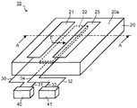
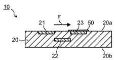
図1は、実施の形態の気流発生装置10を模式的に示した斜視図である。図2は、実施の形態の気流発生装置10が示された図1のA−A断面を模式的に示す図である。なお、図1および図2には、発生する誘起流Fを矢印で示している。
FIG. 1 is a perspective view schematically showing an
図1および図2に示すように、気流発生装置10は、誘電体20、第1の電極21、第2の電極22、第3の電極23を備えている。
As shown in FIGS. 1 and 2, the
誘電体20は、公知な固体の誘電材料で、例えば平板状、膜状などに構成される。誘電体20を構成する材料として具体的には、電気的絶縁材料である、アルミナ、ガラス、マイカなどの無機絶縁物、ポリイミド樹脂、シリコーン樹脂、合成ゴムなどの有機絶縁物などが挙げられる。なお、誘電体20を構成する材料は、これらに限られるものではなく、気流発生装置10が使用される用途や環境に応じて、公知な固体の誘電材料から適宜選択することができる。
The dielectric 20 is a known solid dielectric material, and is configured in, for example, a flat plate shape or a film shape. Specific examples of the material constituting the dielectric 20 include an electrically insulating material such as an inorganic insulator such as alumina, glass, and mica, and an organic insulator such as polyimide resin, silicone resin, and synthetic rubber. In addition, the material which comprises the
なお、発生させる誘起流Fの速度分布などを均一にするため、第1の電極21や第3の電極23が備えられる、誘電体20の少なくとも一方の表面20aは、平面であることが好ましい。
In order to make the velocity distribution of the induced flow F to be generated uniform, at least one
第1の電極21は、図1および図2に示すように、誘電体20の一方の表面20aに設けられている。ここでは、第1の電極21の表面が、誘電体20の一方の表面20aと同一平面上に位置する構成を示している。なお、第1の電極21は、誘電体20の一方の表面20a近傍に位置するように、誘電体20内に埋設されてもよい。また、第1の電極21は、第1の電極21上を流れる気流の妨げとならない程度に、第1の電極21の少なくとも一部を誘電体20の一方の表面20aから突出して配置されてもよい。
As shown in FIGS. 1 and 2, the
第1の電極21は、例えば、薄板や箔などの導電部材で構成される。導電部材としては、気流発生装置10が使用される用途や環境に応じて、公知な導電性材料を使用することができる。第1の電極21は、例えば、銅、金、ニッケル、タングステン、白金などの導電部材を誘電体20の一方の表面20aにコーティングすることで形成されてもよい。
The
第2の電極22は、第1の電極21よりも誘電体20の一方の表面20aから離れた位置で、かつ誘起流Fを流す方向に第1の電極21からずらした位置に、第1の電極21との間に誘電体20を介して設けられている。すなわち、図2に示すように、第2の電極22は、例えば、第1の電極21よりも誘電体20の一方の表面20aから深い位置に埋設されている。さらに、第2の電極22は、誘電体20の一方の表面20a側から見たときに、第1の電極21と全部が重ならないように、第1の電極21から誘起流Fが流れる方向にずらして配置され、第1の電極21とは離間されている。ここで、第1の電極21と第2の電極22との間の距離は、直接放電が発生しないように設定されている。
The
なお、第2の電極22は、誘電体20の一方の表面20a側から見たときに、第1の電極21と全く重ならないように、第1の電極21から誘起流Fの流れ方向にずらして配置されてもよい。また、第2の電極22は、例えば、誘電体20の厚さが薄い場合などには、誘電体20の他方の表面20bに設けられてもよい。第2の電極22は、第1の電極21と対になって、誘電体バリア放電を生じさせるための一対の電極を構成している。
Note that the
第2の電極22は、第1の電極21と同様に、薄板や箔などの導電部材で構成される。また、使用する導電部材も、第1の電極21に使用する導電部材と同じである。
Similar to the
第3の電極23は、誘起流Fを流す方向に第2の電極22からずらした位置で、かつ誘電体20の一方の表面20aに、第2の電極22との間に誘電体20を介して設けられている。すなわち、図2に示すように、第3の電極23は、例えば、誘電体20の一方の表面20a側から見たときに、第2の電極22と全部が重ならないように、第2の電極22から誘起流Fが流れる方向にずらして誘電体20の表面20aに配置され、第2の電極22とは離間されている。ここで、第2の電極22と第3の電極23との間の距離、および第1の電極21と第3の電極23との間の距離は、それぞれの電極間で直接放電が発生しないように設定されている。
The
なお、第3の電極23は、誘電体20の一方の表面20a側から見たときに、第2の電極22と全く重ならないように、第2の電極22から誘起流Fの流れ方向にずらして配置されてもよい。また、ここでは、第3の電極23の表面が、誘電体20の一方の表面20aと同一平面上に位置する構成を示している。なお、第3の電極23は、例えば、第3の電極23上を流れる気流の妨げとならない程度に、第3の電極23の少なくとも一部を誘電体20の一方の表面20aから突出して配置されてもよい。
The
ここで、第3の電極23および第1の電極21は、後に詳しく説明するが、これらの電極間に形成された電界により、第1の電極21と第2の電極22との間の誘電体バリア放電によって誘電体20の一方の表面20a上に生じた荷電粒子を加速するための電極として機能する。
Here, the
第3の電極23は、第1の電極21と同様に、薄板や箔などの導電部材で構成される。また、使用する導電部材も、第1の電極21に使用する導電部材と同じである。
The
図1に示すように、第1の電極21と第2の電極22は、ケーブル30、31を介して第1の電圧印加機構として機能する放電用電源40に接続されている。第2の電極22と第3の電極23は、ケーブル32、33を介して第2の電圧印加機構として機能する加速用電源41に接続されている。ここで、一端を第2の電極22に接続された1つのケーブル34が、他端側で分岐され、ケーブル31およびケーブル33を構成している。これらのケーブル31、33に接続される側が、例えば接地電位となる。
As shown in FIG. 1, the
放電用電源40は、交番電圧を印加する電源であり、パルス状(例えば、四角形などの交流パルス)や交流状(例えば、正弦波、断続正弦波)の波形を有する電圧を出力する。放電用電源40は、電圧値、基本周波数、電流波形、変調周波数、デューティ比などの電流電圧特性などを変化させて、第1の電極21と第2の電極22との間に電圧を印加することができる。
The
加速用電源41は、例えば、第2の電極22と第3の電極23との間に直流電圧を印加する電源で構成される。この場合、例えば、第3の電極23は、負極側の端子に接続される。加速用電源41は、電圧値などの電流電圧特性などを変化させて、第2の電極22と第3の電極23との間に電圧を印加することができる。加速用電源41は、例えば、連続的または断続的に直流電圧を供給することができる。
The
ここで、第1の電極21と第3の電極23との間、および第2の電極22と第3の電極23との間において、直接放電が発生しないように、例えば、第2の電極22と第3の電極23との間に印加される電圧は、第1の電極21と第2の電極22との間に印加される電圧よりも小さくすることが好ましい。
Here, for example, the
また、放電用電源40および加速用電源41によって印加する電圧を調整することで、第3の電極23の電位は、第1の電極21の電位よりも小さくなるように設定される。これによって、第1の電極21から第3の電極23に向かう方向に、電界が形成される。そのため、第1の電極21と第2の電極22との誘電体バリア放電によって生じたプラズマにおける正の電荷を帯びた荷電粒子は、第1の電極21から第3の電極23に向かう方向に加速される。この結果として、第1の電極21から第3の電極23の方向に、誘起流が加速される。
Further, by adjusting the voltage applied by the
ここで、気流発生装置10は、例えば、流体機器などに設置される。流体機器としては、特に限定されるものではないが、例えば、風力発電装置の風車翼、航空機などの翼、自動車のリアウイングスポイラなどのエアロパーツなどが挙げられる。これらの流体機器に気流発生装置10を備えることで、発生した誘起気流により、流体機器を流れる気流を制御し、流体機器における動力の低減や、振動および騒音の抑制を図ることができる。
Here, the
次に、気流発生装置10の作用について説明する。
Next, the operation of the
放電用電源40によって第1の電極21と第2の電極22との間に電圧(例えば、1〜10kV、周波数1〜100Hz)が印加され、一定の閾値以上の電位差となると、第1の電極21と第2の電極22との間に放電が誘起される。この放電は、誘電体バリア放電とよばれ、低温プラズマが生成される。この放電によって、第1の電極21と第2の電極22との間の、誘電体20の一方の表面20a上に荷電粒子が堆積する。
When a voltage (for example, 1 to 10 kV, frequency 1 to 100 Hz) is applied between the
そして、第2の電極22と第3の電極23との間に電圧を印加することで、第1の電極21と第3の電極23との間に電界を形成し、例えば、正の電荷を帯びた荷電粒子は、第1の電極21から第3の電極23に向かう方向に加速される。これによって、第1の電極21から第3の電極23に向かう誘起流Fを発生させることができるとともに、この誘起流Fを加速することができる。
By applying a voltage between the
ここで、第1の電極21と第2の電極22との間にも、誘電体20の表面20a上の荷電粒子を加速する電界が低温プラズマの生成と同時に形成される。しかしながら、荷電粒子が十分に生成された後においては、誘電体20の表面20aの電位が第1の電極21の電位と同一となり、放電は自己消弧し、第1の電極21と第2の電極22との間の電界はほぼ消滅する。そのため、誘電体20の表面20a上に存在する荷電粒子に働く力が無くなり、自己消弧後においては、誘起流Fは発生しない。
Here, an electric field for accelerating charged particles on the
しかしながら、上記したように、第1の電極21と第3の電極23との間に電界を形成することで、誘電体20の表面20a上に存在する荷電粒子に力が働き、誘起流Fを発生させ続けられるとともに、誘起流Fを加速することができる。
However, as described above, by forming an electric field between the
このように、第2の電極22および第3の電極23は、誘起流Fを加速するために、第3の電極23を所定の電位に維持する。また、第1の電極21および第3の電極23は、荷電粒子、すなわち誘起流Fを主として加速する。
In this way, the
上記したように、実施の形態の気流発生装置10によれば、誘電体バリア放電を発生させ低温プラズマを生成するための電極(第1の電極21と第2の電極22)と、生成された低温プラズマにおける荷電粒子を加速、すなわち誘起流Fを加速するための電極を別個に構成することができる。
As described above, according to the
誘起流Fを加速する電極を備えることで、第1の電極21と第2の電極22との間の放電が自己消弧した後においても、誘電体20の表面20a上に存在する荷電粒子を加速することができる。そのため、誘起流Fを交番電圧の一周期の中でより長時間発生させることができる。また、第2の電極22と第3の電極23との間に印加する電圧を制御することで、電界分布を制御して、誘起流Fを所定の流速に設定することも可能となる。
By providing an electrode for accelerating the induced flow F, charged particles existing on the
また、誘電体20の表面20a上に発生するプラズマの状態は、第1の電極21、第2の電極22および誘電体20からなるコンデンサの固有容量で決まるため、発生させたい誘起流Fの速度によっては、誘電体20の材料が制限される。しかしながら、誘起流Fを加速する電極を備えることで、誘電体20の材料が制限されることなく、誘電率の大きな材料を使用することができる。
Further, since the state of the plasma generated on the
このように、誘電率の大きな材料を使用することによって、誘電率の小さな材料を使用した場合に比べて、第1の電極21と第2の電極22との間に同じ電圧を印加しても、誘電体20にかかる電圧が減少し、放電ギャップにかかる電圧が増大する。そのため、荷電粒子の密度を増加させることができ、高速な誘起流Fを発生させることができる。換言すると、同じ速度の誘起流Fを得る場合、誘電率の大きな材料を使用することによって、誘電率の小さな材料を使用した場合における第1の電極21と第2の電極22との間に印加する電圧よりも低電圧で実現することができる。
In this way, by using a material having a large dielectric constant, even when the same voltage is applied between the
ここで、実施の形態の気流発生装置10は、上記した構成に限られるものではない。図3は、実施の形態の気流発生装置10の他の構成を示し、図1のA−A断面に相当する断面を模式的に示す図である。なお、図3には、発生する誘起流Fを矢印で示している。
Here, the
図3に示すように、第3の電極23の表面を誘電体層50で覆ってもよい。誘電体層50は、前述した誘電体20を構成する材料と同じ材料で形成されている。誘電体層50は、例えば、化学気相蒸着(CVD)、スパッタリング、電着などによって形成された薄膜で構成されている。
As shown in FIG. 3, the surface of the
このように、第3の電極23の表面を誘電体層50で覆うことで、第3の電極23が直接プラズマに曝されるのを防止し、第3の電極23の損耗を防止することができる。
Thus, by covering the surface of the
以上説明した実施形態によれば、誘電体バリア放電を生じさせる一対の電極に印加する電圧を抑制しつつ、発生する誘起流の流速を加速させることが可能となる。 According to the embodiment described above, it is possible to accelerate the flow velocity of the induced flow generated while suppressing the voltage applied to the pair of electrodes that cause the dielectric barrier discharge.
本発明のいくつかの実施形態を説明したが、これらの実施形態は、例として提示したものであり、発明の範囲を限定することは意図していない。これら新規な実施形態は、その他の様々な形態で実施されることが可能であり、発明の要旨を逸脱しない範囲で、種々の省略、置き換え、変更を行うことができる。これら実施形態やその変形は、発明の範囲や要旨に含まれるとともに、特許請求の範囲に記載された発明とその均等の範囲に含まれる。 Although several embodiments of the present invention have been described, these embodiments are presented by way of example and are not intended to limit the scope of the invention. These novel embodiments can be implemented in various other forms, and various omissions, replacements, and changes can be made without departing from the scope of the invention. These embodiments and modifications thereof are included in the scope and gist of the invention, and are included in the invention described in the claims and the equivalents thereof.
10…気流発生装置、20…誘電体、20a,20b…表面、21…第1の電極、22…第2の電極、23…第3の電極、30,31,32,33,34…ケーブル、40…放電用電源、41…加速用電源、50…誘電体層、F…誘起流。
DESCRIPTION OF
Claims (5)
固体からなる誘電体と、
前記誘電体の表面に設けられ、または前記誘電体の表面近傍に埋設された第1の電極と、
前記第1の電極よりも前記誘電体の表面から離れた位置で、かつ前記誘起流を流す方向に前記第1の電極からずらした位置に、前記第1の電極との間に前記誘電体を介して設けられた第2の電極と、
前記誘起流を流す方向に前記第2の電極からずらした位置で、かつ前記誘電体の表面に、前記第2の電極との間に前記誘電体を介して設けられた第3の電極と、
前記第1の電極と前記第2の電極との間に交番電圧を印加する第1の電圧印加機構と、
前記第2の電極と前記第3の電極との間に電圧を印加する第2の電圧印加機構と
を具備し、
前記誘起流が、前記第1の電極側から前記第3の電極側に向かって前記誘電体の表面上を流れることを特徴とする気流発生装置。 An airflow generator for generating an induced flow,
A dielectric made of solid,
A first electrode provided on the surface of the dielectric or embedded in the vicinity of the surface of the dielectric;
The dielectric is placed between the first electrode at a position farther from the surface of the dielectric than the first electrode and at a position shifted from the first electrode in the direction in which the induced flow flows. A second electrode provided via,
A third electrode provided at a position shifted from the second electrode in the direction in which the induced flow flows and on the surface of the dielectric, between the second electrode and the second electrode;
A first voltage application mechanism for applying an alternating voltage between the first electrode and the second electrode;
A second voltage application mechanism for applying a voltage between the second electrode and the third electrode;
The airflow generation device characterized in that the induced flow flows on the surface of the dielectric from the first electrode side toward the third electrode side.
Priority Applications (1)
| Application Number | Priority Date | Filing Date | Title |
|---|---|---|---|
| JP2012110542A JP2013236995A (en) | 2012-05-14 | 2012-05-14 | Air current generating device |
Applications Claiming Priority (1)
| Application Number | Priority Date | Filing Date | Title |
|---|---|---|---|
| JP2012110542A JP2013236995A (en) | 2012-05-14 | 2012-05-14 | Air current generating device |
Publications (1)
| Publication Number | Publication Date |
|---|---|
| JP2013236995A true JP2013236995A (en) | 2013-11-28 |
Family
ID=49762533
Family Applications (1)
| Application Number | Title | Priority Date | Filing Date |
|---|---|---|---|
| JP2012110542A Pending JP2013236995A (en) | 2012-05-14 | 2012-05-14 | Air current generating device |
Country Status (1)
| Country | Link |
|---|---|
| JP (1) | JP2013236995A (en) |
Cited By (5)
| Publication number | Priority date | Publication date | Assignee | Title |
|---|---|---|---|---|
| CN104185354A (en) * | 2014-04-10 | 2014-12-03 | 中国商用飞机有限责任公司北京民用飞机技术研究中心 | Dielectric barrier discharge plasma exciter and system |
| JP2015195162A (en) * | 2014-03-28 | 2015-11-05 | 清水 一男 | Electrode for generating low voltage plasma and plasma radiation method using the same |
| WO2017141712A1 (en) * | 2016-02-16 | 2017-08-24 | 株式会社Ihi | Method for producing blade structure |
| JP2020024845A (en) * | 2018-08-07 | 2020-02-13 | トヨタ自動車株式会社 | Method for controlling ionic wind generator |
| JP2021072204A (en) * | 2019-10-30 | 2021-05-06 | 株式会社Ihi | Plasma actuator |
-
2012
- 2012-05-14 JP JP2012110542A patent/JP2013236995A/en active Pending
Cited By (8)
| Publication number | Priority date | Publication date | Assignee | Title |
|---|---|---|---|---|
| JP2015195162A (en) * | 2014-03-28 | 2015-11-05 | 清水 一男 | Electrode for generating low voltage plasma and plasma radiation method using the same |
| CN104185354A (en) * | 2014-04-10 | 2014-12-03 | 中国商用飞机有限责任公司北京民用飞机技术研究中心 | Dielectric barrier discharge plasma exciter and system |
| WO2017141712A1 (en) * | 2016-02-16 | 2017-08-24 | 株式会社Ihi | Method for producing blade structure |
| JPWO2017141712A1 (en) * | 2016-02-16 | 2018-12-06 | 株式会社Ihi | Manufacturing method of wing structure |
| US11078794B2 (en) | 2016-02-16 | 2021-08-03 | Ihi Corporation | Airfoil structure manufacturing method |
| JP2020024845A (en) * | 2018-08-07 | 2020-02-13 | トヨタ自動車株式会社 | Method for controlling ionic wind generator |
| JP2021072204A (en) * | 2019-10-30 | 2021-05-06 | 株式会社Ihi | Plasma actuator |
| JP7285193B2 (en) | 2019-10-30 | 2023-06-01 | 株式会社Ihi | plasma actuator |
Similar Documents
| Publication | Publication Date | Title |
|---|---|---|
| JP6566503B2 (en) | Fluid machinery | |
| JP2013236995A (en) | Air current generating device | |
| EP3147207B1 (en) | Embedded dielectric structures for active flow control plasma sources | |
| CN107914865B (en) | Plasma virtual dynamic bionic device and method for wing leading edge | |
| US20160230783A1 (en) | Airflow generation device | |
| JP5259528B2 (en) | Airflow generator and moving body | |
| JP2012241732A (en) | Airflow control device, and airflow control method | |
| JP6444797B2 (en) | Wind power generation system | |
| CN102756803A (en) | Pneumatic gurney flap based on plasma wall surface jet flow | |
| KR101381872B1 (en) | Plasma film for airflow control | |
| JP7181653B2 (en) | plasma actuator | |
| JP2018004059A (en) | Airflow control apparatus and airflow control method | |
| CN116614927A (en) | Grid-shaped plasma exciter for turbulence resistance reduction | |
| JP6421296B2 (en) | Plasma actuator | |
| US11293459B2 (en) | Fan device | |
| JP6523065B2 (en) | Airflow generator and wind power generation system | |
| JP6491981B2 (en) | Airflow generator and wind power generation system | |
| CN113285628A (en) | High-output-performance multi-pulse generator and system based on micro-gap corona discharge | |
| JP2018003617A (en) | Wind generator system | |
| JP2021072204A (en) | Plasma actuator | |
| CN104302085A (en) | Non air contact type plasma bipolar exciting electrode and plasma exciter | |
| JP2013077376A (en) | Airflow generation device | |
| JP6403156B2 (en) | Airflow generator and wind power generation system | |
| WO2013121684A1 (en) | Ion generator | |
| Matsuno et al. | Parametric Optimization of Multi-Electrode Plasma Actuator with Serrated Electrode |