JP2013236806A - Waist exercise machine - Google Patents

Waist exercise machine Download PDF

Info

Publication number
JP2013236806A
JP2013236806A JP2012112522A JP2012112522A JP2013236806A JP 2013236806 A JP2013236806 A JP 2013236806A JP 2012112522 A JP2012112522 A JP 2012112522A JP 2012112522 A JP2012112522 A JP 2012112522A JP 2013236806 A JP2013236806 A JP 2013236806A
Authority
JP
Japan
Prior art keywords
lower limb
exercise machine
user
drive mechanism
placement
Prior art date
Legal status (The legal status is an assumption and is not a legal conclusion. Google has not performed a legal analysis and makes no representation as to the accuracy of the status listed.)
Granted
Application number
JP2012112522A
Other languages
Japanese (ja)
Other versions
JP5542170B2 (en
Inventor
Teruo Mihara
輝男 三原
Shinsaku Shimizu
新策 清水
Current Assignee (The listed assignees may be inaccurate. Google has not performed a legal analysis and makes no representation or warranty as to the accuracy of the list.)
Daito Electric Machine Industry Co Ltd
Original Assignee
Daito Electric Machine Industry Co Ltd
Priority date (The priority date is an assumption and is not a legal conclusion. Google has not performed a legal analysis and makes no representation as to the accuracy of the date listed.)
Filing date
Publication date
Application filed by Daito Electric Machine Industry Co Ltd filed Critical Daito Electric Machine Industry Co Ltd
Priority to JP2012112522A priority Critical patent/JP5542170B2/en
Publication of JP2013236806A publication Critical patent/JP2013236806A/en
Application granted granted Critical
Publication of JP5542170B2 publication Critical patent/JP5542170B2/en
Active legal-status Critical Current
Anticipated expiration legal-status Critical

Links

Images

Abstract

PROBLEM TO BE SOLVED: To provide a waist exercise machine that applies pulling motion, twist movement, or the like to the waist of a user easily at home or the like.SOLUTION: A waist exercise machine 1 includes a lower leg placing part 4 on which a lower leg of a user U is placed, the user being in a supine posture; and a drive mechanism 6 for at least vertically swinging the lower leg placing part 4 in a reciprocating manner. The drive mechanism 6 swings the lower leg placing part 4 in the reciprocating manner in a horizontal direction and/or a longitudinal direction with vertical reciprocating movement of the lower leg placing part 4.

Description

本発明は、使用者の腰部に対して効果的な引っ張り乃至は捻り運動を付与することが可能な運動機に関する。   The present invention relates to an exercise machine capable of imparting effective pulling or twisting motion to a user's waist.

使用者の腰部に対して引っ張り力を付与する機器、言い換えれば使用者の腰椎を牽引する装置としては、例えば、特許文献1に開示されたものがある。
特許文献1の腰椎牽引装置は、骨盤を固定するベルトと、当該ベルトの一端を座部に係止する係止部と、当該ベルトの他端を巻き取るベルト巻取部と、ベルトの張力を検出するベルト張力検出部とを設けて、ベルトを患者の骨盤部に装着してその一端を座席部に係止し、ベルト巻取部を作動させて当該ベルトの他端を巻取ってベルトの張力が所定値になるようにして、骨盤を確実に固定するようにした構成を有している。この構成により、特許文献1に開示された腰椎牽引機器は、骨盤固定をより確実にして治療効果を向上させるとともに、介助者の手間を省力化するとしている。
As an apparatus for applying a pulling force to the user's waist, in other words, an apparatus for pulling the user's lumbar spine, there is one disclosed in Patent Document 1, for example.
The lumbar traction device of Patent Document 1 includes a belt for fixing a pelvis, a locking portion for locking one end of the belt to a seat, a belt winding portion for winding the other end of the belt, and a tension of the belt. A belt tension detecting unit for detecting the belt, attaching the belt to the patient's pelvis, locking one end of the belt to the seat, operating the belt take-up unit to wind up the other end of the belt, The structure is such that the pelvis is securely fixed so that the tension becomes a predetermined value. With this configuration, the lumbar traction device disclosed in Patent Document 1 improves the therapeutic effect by making pelvic fixation more reliable, and saves the labor of the assistant.

特開2010−12249号公報JP 2010-12249 A

しかしながら、特許文献1の腰椎牽引装置は、病院のような本格的な治療施設での使用を意図したものであって、非常に大型であり、一般の使用者が自宅で使用するには、困難を伴うものであった。通常、多くの人は、腰がだるいといった不快感を日常抱きがちであり、この不快感を自宅などで簡単に解消できる装置を所望するものであって、この要望に対しても、特許文献1の腰椎牽引装置は応えるものとはなっていない。   However, the lumbar traction device of Patent Document 1 is intended for use in a full-scale treatment facility such as a hospital, is very large, and is difficult for general users to use at home. It was accompanied by. Usually, many people tend to embrace the feeling of unpleasantness in daily life, and a device that can easily eliminate this discomfort at home or the like is desired. The lumbar traction device is not a response.

そこで、本発明は、上記した問題に鑑み、使用者が自宅などで簡単に腰部への牽引動作や捻り運動などを付与できる腰部運動機を提供することを目的とする。   In view of the above-described problems, an object of the present invention is to provide a waist exercise machine that allows a user to easily apply a pulling operation or a twisting exercise to the waist at home or the like.

前記目的を達成するため、本発明においては以下の技術的手段を講じた。
すなわち、本発明に係る腰部運動機は、仰臥姿勢とされた使用者の下肢が載置される下肢載置部と、この下肢載置部を上下方向に往復移動させる駆動機構と、を有することを特徴とする。
また、本発明に係る腰部運動機は、仰臥姿勢とされた使用者の下肢が載置される下肢載置部と、この下肢載置部を左右方向に往復移動させる駆動機構と、を有することを特徴とする。
また、本発明に係る腰部運動機は、仰臥姿勢とされた使用者の下肢が載置される下肢載置部と、この下肢載置部を前後方向に往復移動させる駆動機構と、を有することを特徴とする。
また、本発明に係る腰部運動機は、仰臥姿勢とされた使用者の下肢が掛けられ且つ前記下肢の膝窩が載置される下肢載置部と、この下肢載置部を少なくとも上下方向に往復揺動させる駆動機構と、を有し、前記駆動機構は、下肢載置部が上下方向に往復移動するに伴って、下肢載置部を左右方向及び前後方向に往復揺動させるように構成されていることを特徴とする。
In order to achieve the above object, the present invention takes the following technical means.
That is, the lower back exercise machine according to the present invention has a lower limb placement portion on which a user's lower limb in a supine posture is placed, and a drive mechanism that reciprocates the lower limb placement portion in the vertical direction. It is characterized by.
Further, the lower back exercise machine according to the present invention has a lower limb placement portion on which a user's lower limb placed in a supine posture is placed, and a drive mechanism that reciprocates the lower limb placement portion in the left-right direction. It is characterized by.
Further, the lower back exercise machine according to the present invention has a lower limb placement portion on which a user's lower limb placed in a supine posture is placed, and a drive mechanism that reciprocates the lower limb placement portion in the front-rear direction. It is characterized by.
Further, the lower back exercise machine according to the present invention includes a lower limb placement portion on which a user's lower limb in a supine posture is hung and a popliteum of the lower limb is placed, and the lower limb placement portion at least vertically. And a drive mechanism configured to reciprocally swing the lower limb placement portion in the left-right direction and the front-rear direction as the lower limb placement portion reciprocates in the vertical direction. It is characterized by being.

上記した腰部運動機において、好ましくは、前記下肢載置部は、二叉に分かれた載置棒体を有しており、一方の載置棒体に使用者の一方の下肢が載置され、他方の載置棒体に使用者の他方の下肢が載置されるように構成されているとよい。
好ましくは、前記駆動機構は、下肢載置部を左右方向及び前後方向に往復移動させる第1の揺動機構を備えているとよい。
In the above-described lumbar exercise machine, preferably, the lower limb placement unit has a bifurcated placement rod body, and one of the user's lower limbs is placed on one placement rod body, It is good to be comprised so that a user's other leg may be mounted in the other mounting rod body.
Preferably, the drive mechanism may include a first swing mechanism that reciprocally moves the lower limb placement portion in the left-right direction and the front-rear direction.

好ましくは、前記駆動機構は、下肢載置部を上下方向に往復移動させる第2の揺動機構を備えているとよい。   Preferably, the drive mechanism may include a second swinging mechanism that reciprocates the lower limb placement unit in the up-down direction.

本発明に係る腰部運動機によれば、使用者が自宅などで簡単に腰部への牽引動作や捻り運動などを付与できるようになる。   According to the lumbar exercise machine according to the present invention, the user can easily give a traction operation or a twisting exercise to the lumbar region at home or the like.

本発明に係る腰部運動機の斜視図である。It is a perspective view of the lower back exercise machine concerning the present invention. 本発明に係る腰部運動機の左側面図である。It is a left view of the lower back exercise machine according to the present invention. 本発明に係る腰部運動機の上面図である。It is a top view of the lower back exercise machine according to the present invention. 本発明に係る腰部運動機の使用態様図である。It is a use mode figure of the lower back exercise machine concerning the present invention. 揺動変換部の断面図である。It is sectional drawing of a rocking | swiveling conversion part.

以下に、本発明の腰部運動機1を図を基に説明する。なお、説明においては、図2の左右方向を説明での後前方向とし、図2の上下方向を説明での上下方向とする。図3の左右方向を説明での左右方向とする。
図1、図2に示すように、本発明の腰部運動機1は、床面F上に載置される水平基板2とこの水平基板2の後方縁から垂直に立設された垂直基板3とを有している。垂直基板3の上側部からは前方に突出するよう下肢載置部4が設けられている。
Below, the waist exercise machine 1 of this invention is demonstrated based on a figure. In the description, the left-right direction in FIG. 2 is the rear front direction in the description, and the up-down direction in FIG. 2 is the up-down direction in the description. The left-right direction in FIG. 3 is the left-right direction in the description.
As shown in FIGS. 1 and 2, the lower back exercise machine 1 of the present invention includes a horizontal substrate 2 placed on a floor surface F, and a vertical substrate 3 erected vertically from a rear edge of the horizontal substrate 2. have. A lower limb resting portion 4 is provided so as to protrude forward from the upper portion of the vertical substrate 3.

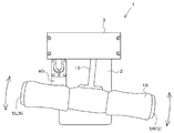
図3に示すように、この下肢載置部4は、平面視でT字形状を呈しており、左右方向それぞれに突出する二叉に分かれた一対の載置棒体5(右載置棒体5R、左載置棒体5L)を有している。この下肢載置部4は、駆動機構6により、上下方向に往復揺動されるものとなっている。さらに、下肢載置部4は、駆動機構6により、左右方向や前後方向に往復揺動されるものとなっている。すなわち、駆動機構6は、下肢載置部4を上下方向に揺動させると共に、下肢載置部4を前後、左右に移動するようになっている。   As shown in FIG. 3, the lower limb placing portion 4 has a T shape in plan view, and has a pair of bifurcated placing rods 5 (right placing rods) protruding in the left and right directions. 5R, left mounting rod 5L). The lower limb placement unit 4 is reciprocally swung in the vertical direction by a drive mechanism 6. Further, the lower limb placement unit 4 is reciprocally swung in the left-right direction and the front-rear direction by the drive mechanism 6. That is, the drive mechanism 6 swings the lower limb placement unit 4 in the vertical direction and moves the lower limb placement unit 4 in the front-rear and left-right directions.

すなわち、図1、図3の矢印に示すように、駆動機構6は、右載置棒体5Rが下に傾いたときには、左載置棒体5Lが上に傾き、右載置棒体5Rが上に傾いたときには、左載置棒体5Lが下に傾くように揺動する。同時に右載置棒体5Rが前側に移動した際には、左載置棒体5Lが後側に移動し、右載置棒体5Rが後側に移動した際には、左載置棒体5Lが前側に移動するようになり、うねるような動作(うねり運動)を呈するようになる。併せて、図2の矢印に示すように、このようなうねり運動をする一対の載置棒体5が、駆動機構6により、大きく上下に往復移動することとなる。   That is, as shown by the arrows in FIG. 1 and FIG. 3, when the right mounting bar 5R is tilted downward, the drive mechanism 6 has the left mounting bar 5L tilted upward and the right mounting bar 5R tilted. When tilted upward, the left mounting rod 5L swings so as to tilt downward. At the same time, when the right mounting bar 5R moves to the front side, the left mounting bar 5L moves to the rear side, and when the right mounting bar 5R moves to the rear side, the left mounting bar body 5L moves to the front side and exhibits a swell motion (swell motion). In addition, as shown by the arrows in FIG. 2, the pair of mounting rod bodies 5 that make such a swell movement are reciprocally moved up and down by the drive mechanism 6.

以上述べた下肢載置部4の動きを実現すべく、駆動機構6は、下肢載置部4を左右方向及び前後方向に往復揺動させる第1の揺動機構7を備えている。加えて、駆動機構6は、下肢載置部4を上下方向に往復移動させる第2の揺動機構8を備えている。第1の揺動機構7及び第2の揺動機構8の詳細な説明は後述する。
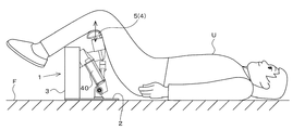
図4は、本発明の腰部運動機1の使用態様を示したものである。
In order to realize the movement of the lower limb placement unit 4 described above, the drive mechanism 6 includes a first swing mechanism 7 that reciprocally swings the lower limb placement unit 4 in the left-right direction and the front-rear direction. In addition, the drive mechanism 6 includes a second swinging mechanism 8 that reciprocates the lower limb placement unit 4 in the vertical direction. Detailed description of the first swing mechanism 7 and the second swing mechanism 8 will be described later.
FIG. 4 shows a usage mode of the lower back exercise machine 1 of the present invention.

本発明の腰部運動機1を使用して、腰部に対して牽引や捻り運動を付与させるにあたっては、使用者Uは、腰部運動機1を載置した床面F上に、上向きに寝る姿勢(仰臥姿勢)を取るようにする。その上で、下肢載置部4の上面に対し下肢の膝窩(ひざの後ろのくぼんでいる所、ひかがみ)が載置されるように、使用者Uの下肢を下肢載置部4に掛ける。具体的には、右の載置棒体5に使用者Uの右の下肢が載置され、左の載置棒体5に左の下肢が載置されるようにする。   In using the lumbar exercise machine 1 of the present invention to give a traction or twisting motion to the lumbar part, the user U sleeps on the floor F on which the lumbar exercise machine 1 is placed ( Take a supine posture). In addition, the lower limb of the user U is placed on the lower limb placement unit 4 so that the popliteal of the lower limb (the recessed portion behind the knee, the bow) is placed on the upper surface of the lower limb placement unit 4. Multiply. Specifically, the lower leg of the user U is placed on the right placement bar 5, and the left leg is placed on the left placement bar 5.

なお、下肢載置部4に載置する下肢の部位は、膝窩に限定されない。ふくらはぎの部分でもよく足首の部分でもよい。使用者の膝から足先に亘ってのいずれかの部位を下肢載置部4に載置するようにするとよい。
その上で、腰部運動機1を動作させると、第1の揺動機構7により、左右一対の載置棒体5がうねるような動きをする。この動きは、下肢を通じて、使用者Uの腰部へと伝わる。使用者Uは床面F上に寝ているため、その上体は床面F上のほぼ一定の位置に存在することとなる(上体がほぼ固定された状態)。そのため、左右一対の載置棒体5のうねるような動きは、腰部へと作用し、腰部に対し捻り運動を付与するようになる。
In addition, the site | part of the leg which mounts on the leg mounting part 4 is not limited to a popliteal. It may be a calf or ankle. It is preferable to place any part from the user's knee to the toe on the lower limb placement unit 4.
Then, when the lower back exercise machine 1 is operated, the pair of left and right mounting rod bodies 5 move by the first swing mechanism 7. This movement is transmitted to the user's U waist through the lower limbs. Since the user U is sleeping on the floor surface F, the upper body exists at a substantially constant position on the floor surface F (a state where the upper body is substantially fixed). Therefore, the undulating movement of the pair of left and right mounting rods 5 acts on the waist and imparts a twisting motion to the waist.

同時に、第2の揺動機構8により、左右一対の載置棒体5が上下に往復移動する。この上下往復移動の動きは、下肢を通じて、使用者Uの腰部へと伝わる。使用者Uは床面F上
に寝ているため、その上体は床面F上のほぼ一定の位置に存在することとなる故、左右一対の載置棒体5の上下動は、腰部へと作用し、腰部に対し引っ張り(腰の牽引)運動を付与するようになる。
At the same time, the pair of left and right mounting bars 5 reciprocate up and down by the second swing mechanism 8. This vertical reciprocating movement is transmitted to the user's U waist through the lower limbs. Since the user U is sleeping on the floor surface F, the upper body is present at a substantially constant position on the floor surface F, and therefore, the vertical movement of the pair of left and right mounting rod bodies 5 moves to the waist. Acts to give a pulling (waist pulling) motion to the waist.

以上述べたように、本発明の腰部運動機1を用いることで、一般の使用者Uが自宅などで簡単に腰部への牽引動作やひねり運動などを付与できるようになる。本発明の腰部運動機1は、例えば、特許文献1の腰椎牽引装置のように、病院のような本格的な治療施設での使用を意図したものはなく、非常にコンパクトで、使用者Uが自宅などで使用するには、最適な装置となっている。腰がだるいといった不快感を日常抱きがちの使用者Uは、本装置を用いることで、係る腰の不快感を自宅などで簡単に解消できるようになる。   As described above, by using the lower back exercise machine 1 of the present invention, a general user U can easily give a pulling operation or a twisting exercise to the lower back at home or the like. The lumbar exercise machine 1 of the present invention is not intended to be used in a full-scale treatment facility such as a hospital like the lumbar traction device of Patent Document 1, and is very compact. It is an optimal device to use at home. By using this apparatus, the user U who tends to feel unpleasant feelings such as dullness can easily eliminate such unpleasant feelings at home or the like.

本発明に備えられた腰部運動機1の駆動機構6としては、様々な機構が採用可能であるが、本実施形態では、図1〜図3、図5に示すような機構を採用している。
まず、図1に示すように、腰部運動機1は、床面F上に載置される水平基板2とこの水平基板2の後方縁から垂直に立設された垂直基板3とを有している。
垂直基板3の上側部には、第1の揺動機構7が設けられている。すなわち、垂直基板3の上側部には、第1回転軸10が左右方向を向くように設けられている。第1回転軸10の両側は軸受部12で回転自在に支持されている。左側の軸受部12に関しては、第1回転軸10が貫通状に設けられており、左側の軸受部12のさらに左側に設けられた駆動モータ機構9に連結されるようになっている。
Various mechanisms can be employed as the drive mechanism 6 of the lower back exercise machine 1 provided in the present invention, but in the present embodiment, a mechanism as shown in FIGS. 1 to 3 and 5 is employed. .
First, as shown in FIG. 1, the lower back exercise machine 1 has a horizontal substrate 2 placed on the floor surface F and a vertical substrate 3 erected vertically from the rear edge of the horizontal substrate 2. Yes.
A first swing mechanism 7 is provided on the upper portion of the vertical substrate 3. That is, the first rotating shaft 10 is provided on the upper side of the vertical substrate 3 so as to face in the left-right direction. Both sides of the first rotating shaft 10 are rotatably supported by the bearing portion 12. With respect to the left bearing portion 12, the first rotating shaft 10 is provided in a penetrating manner, and is connected to a drive motor mechanism 9 provided further to the left of the left bearing portion 12.

第1回転軸10の略中央部からは、前方(使用者側)に突出するブラケット部13が設けられている。第1回転軸10はこのブラケット部13の基端部(後端部)を貫通するように設けられており、このブラケット部13の基端部には、第1回転軸10の回転運動をブラケット部13の揺動運動に変換する揺動変換部14が設けられている。揺動変換部14の詳細は後述する。   A bracket portion 13 that protrudes forward (on the user side) is provided from a substantially central portion of the first rotating shaft 10. The first rotating shaft 10 is provided so as to pass through the proximal end portion (rear end portion) of the bracket portion 13, and the rotational motion of the first rotating shaft 10 is bracketed to the proximal end portion of the bracket portion 13. A swing conversion part 14 for converting the swing motion of the part 13 is provided. Details of the swing converter 14 will be described later.

ブラケット部13の先端部からは、上方に突出する突出部15が設けられ、突出部15の上面には左右方向に突出する二叉状の棒部材、すなわち左載置棒体5L及び右載置棒体5Rが突出している。この載置棒体5は使用者Uの下肢を引っかけることができる程度の長さを有しており、載置棒体5の上面には、使用者Uに下肢に対する当たりを柔らかくするために、クッション部材16が貼り付けられている。   A protruding portion 15 that protrudes upward is provided from the distal end portion of the bracket portion 13, and a bifurcated bar member that protrudes in the left-right direction on the upper surface of the protruding portion 15, that is, the left mounting rod 5 </ b> L and the right mounting rod. The rod body 5R protrudes. The mounting bar 5 has a length that can hook the lower limbs of the user U, and the upper surface of the mounting bar 5 has a soft contact with the lower limbs of the user U. A cushion member 16 is affixed.

ブラケット部13、ひいては左右一対の載置棒体5に左右、前後方向の揺動を与えるための揺動変換部14は、以下のような構造を有している。
すなわち、図5に示すように、揺動変換部14は、第1回転軸10に取り付けられると共にこの第1回転軸10の回転に伴い回転する回転ボス部20と、回転ボス部20の外側に嵌り込む環状嵌合部21とで構成されている。回転ボス部20は、第1回転軸10の軸心方向中央部に配置され、回転ボス部20は、回転軸に対して傾斜した略円形であって無端状の軌道(カム面22)を有するものとなっている。
The swing conversion portion 14 for giving the left and right and front and rear swings to the bracket portion 13 and thus the pair of left and right mounting rods 5 has the following structure.
That is, as shown in FIG. 5, the swing conversion portion 14 is attached to the first rotating shaft 10 and rotates with the rotation of the first rotating shaft 10, and on the outer side of the rotating boss portion 20. It is comprised with the annular fitting part 21 to fit. The rotating boss portion 20 is disposed at the central portion in the axial center direction of the first rotating shaft 10, and the rotating boss portion 20 has a substantially circular and endless track (cam surface 22) inclined with respect to the rotating shaft. It has become a thing.

具体的には、回転ボス部20は、略円柱形状で無端状の軌道(カム面22)が外周面に形成されている内カム部材23と、略円柱形状であって内カム部材23の一方の端面に対面するような端面を有する外カム部材24とで構成されている。この内外のカム部材23,24は、各端面が接するように付き合わされる共にネジでネジ止めされ一体となって組み合わされる。回転ボス部20は、第1回転軸10に相対回転できないように固定されている。   Specifically, the rotating boss portion 20 includes an inner cam member 23 having a substantially cylindrical shape and an endless track (cam surface 22) formed on the outer peripheral surface, and one of the inner cam member 23 having a substantially cylindrical shape. And an outer cam member 24 having an end face facing the end face. The inner and outer cam members 23 and 24 are brought together so that their end faces are in contact with each other, and are screwed together with screws to be combined together. The rotating boss portion 20 is fixed so as not to rotate relative to the first rotating shaft 10.

カム面22は、内カム部材23の端面に隣接する外周面に形成されている。回転ボス部20のカム面22は、回転軸に対して同じ向きに傾斜するようになっている。内カム部材23のカム面22には、ベアリング25が摺動自在に嵌合され、環状嵌合部21が回動自在になっている。
環状嵌合部21は、回転ボス部20のカム面22上に嵌り込んだベアリング25を外嵌し、回転ボス部20の回転を揺動運動に変換するものである。環状嵌合部21は、側面視略環状に形成され、略中央部には、回転ボス部20の大きさの円状の開口部が開口されている。この開口部は、カム面22上に嵌め込まれたベアリング25の外周面を外嵌している。そのため、回転ボス部20と環状嵌合部21とが相対回動自在になっている。
The cam surface 22 is formed on the outer peripheral surface adjacent to the end surface of the inner cam member 23. The cam surface 22 of the rotating boss portion 20 is inclined in the same direction with respect to the rotation axis. A bearing 25 is slidably fitted to the cam surface 22 of the inner cam member 23, and the annular fitting portion 21 is rotatable.
The annular fitting portion 21 externally fits a bearing 25 fitted on the cam surface 22 of the rotating boss portion 20 and converts the rotation of the rotating boss portion 20 into a swinging motion. The annular fitting part 21 is formed in a substantially annular shape in a side view, and a circular opening having a size of the rotating boss part 20 is opened in a substantially central part. This opening is fitted on the outer peripheral surface of the bearing 25 fitted on the cam surface 22. For this reason, the rotating boss portion 20 and the annular fitting portion 21 are relatively rotatable.

図1、図2などに示すように、ブラケット部13の先端部でその下面には、当該ブラケット部13が第1回転軸10の回転と供回りすることを規制するための規制部28が配備されている。
この規制部28は、ブラケット部13の先端部の下面から下方突出するように形成された規制突起29を有している。この規制突起29の先端(下端)は、球状体30とされている。この球状体30は、後述する第2の揺動機構8を構成する第2クランク体36の先端部に設けられた球状凹部37に、摺動自在に嵌り込んでいる。この第2クランク体36によりブラケット部13は位置固定されている(所定範囲内のみで上下・前後・左右に移動可能)ため、第1回転軸10が回転したとしても、ブラケット部13は、第1回転軸10と共に連れ回ることがなくなる。
As shown in FIG. 1 and FIG. 2, a restricting portion 28 for restricting the bracket portion 13 from rotating with the rotation of the first rotating shaft 10 is provided on the lower surface of the front end portion of the bracket portion 13. Has been.
The restricting portion 28 has a restricting protrusion 29 formed so as to protrude downward from the lower surface of the front end portion of the bracket portion 13. The tip (lower end) of the restriction projection 29 is a spherical body 30. The spherical body 30 is slidably fitted into a spherical concave portion 37 provided at the tip of a second crank body 36 constituting the second swing mechanism 8 described later. Since the bracket portion 13 is fixed in position by the second crank body 36 (movable up and down, front and rear, and left and right only within a predetermined range), even if the first rotating shaft 10 rotates, the bracket portion 13 There is no need to follow the rotating shaft 10 together.

一方、図1、図2に示すように、腰部運動機1を構成する水平基板2上の前後方向略中央部であって、ブラケット部13の直下に対応する所には、第2回転軸32が左右方向を向くように設けられている。第2回転軸32の両側は軸受部12で回転自在に支持されている。左側の軸受部12に関しては、第2回転軸32が貫通状に設けられており、左側の軸受部12のさらに左側に設けられた駆動モータ機構9に連結されるようになっている。   On the other hand, as shown in FIGS. 1 and 2, the second rotating shaft 32 is provided at a substantially central portion in the front-rear direction on the horizontal substrate 2 constituting the lower back exercise machine 1 and corresponding to a position directly below the bracket portion 13. Is provided to face in the left-right direction. Both sides of the second rotating shaft 32 are rotatably supported by the bearing portion 12. With respect to the left bearing portion 12, a second rotating shaft 32 is provided in a penetrating manner and is connected to a drive motor mechanism 9 provided further to the left of the left bearing portion 12.

第2回転軸32の略中央部には、第2回転軸32の軸心に対し直交方向に突出する突出片、言い換えればクランクスロー34が設けられている。クランクスロー34は左右一対で所定間隔を開けて設けられており、このクランクスロー34の基端部は第2回転軸32と一体回転するように固定されている。クランクスロー34の先端部には左右軸心回りに回転自在となるように、長棒状で上下方向を向く第1クランク体35(コネクティングロッド)の下端部が取り付けられている。この第1クランク体35は単一の棒体で構成され、その下端部は左右一対に設けられたクランクスロー34に挟まれるように配備されている。   A projecting piece that projects in a direction orthogonal to the axis of the second rotating shaft 32, in other words, a crank throw 34 is provided at a substantially central portion of the second rotating shaft 32. A pair of left and right crank throws 34 are provided at predetermined intervals, and a base end portion of the crank throw 34 is fixed so as to rotate integrally with the second rotary shaft 32. A lower end portion of a first crank body 35 (connecting rod) is attached to the front end portion of the crank throw 34 so as to be rotatable around the left and right axial centers and is in the shape of a long bar and facing in the vertical direction. The first crank body 35 is composed of a single rod body, and the lower end portion thereof is disposed so as to be sandwiched between a pair of left and right crank throws 34.

第1クランク体35の上端部には、この第1クランク体35よりは短い棒状の第2クランク体36が取り付けられている。第2クランク体36の下端部は、第1クランク体35の上端部に対して前後軸心回りに回動自在に連結されている。第2クランク体36の上面(上端部)には、前述した球状凹部37が形成されており、この球状凹部37に、ブラケット部13の先端の下部から突出するように形成された規制突起29が摺動自在に嵌り込んでおり、ボールジョイント機構を形成している。   A rod-like second crank body 36 shorter than the first crank body 35 is attached to the upper end portion of the first crank body 35. The lower end portion of the second crank body 36 is connected to the upper end portion of the first crank body 35 so as to be rotatable around the front-rear axis. The spherical recess 37 described above is formed on the upper surface (upper end) of the second crank body 36, and a restriction projection 29 formed so as to protrude from the lower end of the tip of the bracket portion 13 is formed in the spherical recess 37. It is slidably fitted to form a ball joint mechanism.

図1に示す如く、以上述べた第1回転軸10及び第2回転軸32に対して回転駆動力を与えるために、腰部運動機1の左側に、駆動モータ機構9が設けられている。この駆動モータ機構9は単一の電動モータ40を備えており、この電動モータ40は、水平基板2の上部から垂直基板3の前部に向けて斜めになるように配備されている(図2参照)。この電動モータ40は、その上端側と下端側のそれぞれに駆動回転軸が突出状に設けられており、上側の駆動回転軸はウォームギア機構を介して第1回転軸10へ繋がるようになっている。下側の駆動回転軸はウォームギア機構を介して第2回転軸32へ繋がるようになっている。   As shown in FIG. 1, a drive motor mechanism 9 is provided on the left side of the lower back exercise machine 1 in order to give a rotational drive force to the first rotary shaft 10 and the second rotary shaft 32 described above. The drive motor mechanism 9 includes a single electric motor 40, and this electric motor 40 is disposed so as to be inclined from the upper part of the horizontal board 2 toward the front part of the vertical board 3 (FIG. 2). reference). The electric motor 40 is provided with a drive rotation shaft protruding from the upper end side and the lower end side thereof, and the upper drive rotation shaft is connected to the first rotation shaft 10 via a worm gear mechanism. . The lower drive rotation shaft is connected to the second rotation shaft 32 via a worm gear mechanism.

以上述べた構成を有しているため、駆動モータ機構9の電動モータ40を回転させると、その回転駆動力は、ウォームギア機構を介して第1回転軸10へ伝達される。第1回転軸10の回転駆動力は、揺動変換部14により、ブラケット部13、言い換えれば載置棒体5の揺動運動(主に左右、前後の往復揺動運動)へと変換される。同時に、電動モータ40の回転駆動力は、ウォームギア機構を介して第2回転軸32へ伝達される。第2回転軸32の回転駆動力は、クランクスロー34を左右軸心回り回転させることになり、それに伴って、第1クランク体35及び第2クランク体36を上下方向に往復移動させる。往復移動の振幅は、クランクスロー34の長さの約2倍である。この上下往復移動は、規制部28を介してブラケット部13へ伝えられ、下肢載置部4の揺動運動(主に上下の往復揺動運動)へと変換される。   Since it has the configuration described above, when the electric motor 40 of the drive motor mechanism 9 is rotated, the rotational driving force is transmitted to the first rotary shaft 10 via the worm gear mechanism. The rotational driving force of the first rotating shaft 10 is converted by the swing conversion portion 14 into swing motion (mainly reciprocating swing motion in the left and right and front and rear directions) of the bracket portion 13, in other words, the mounting rod body 5. . At the same time, the rotational driving force of the electric motor 40 is transmitted to the second rotating shaft 32 via the worm gear mechanism. The rotational driving force of the second rotating shaft 32 causes the crank throw 34 to rotate about the left and right axis, and accordingly, the first crank body 35 and the second crank body 36 are reciprocated in the vertical direction. The amplitude of the reciprocating movement is about twice the length of the crank throw 34. This up-and-down reciprocating movement is transmitted to the bracket portion 13 via the restricting portion 28 and converted into a swinging motion (mainly a vertical reciprocating swinging motion) of the lower limb resting portion 4.

第2クランク体36は、第1クランク体35に対して前後軸心回りに揺動自在であり、ブラケット部13と第2クランク体36とはピボット揺動可能とされたボールジョイント機構で連結されているため、クランクスロー34で生成された上下揺動の動きは、揺動変
換部14により生成される揺動運動を妨げることにはならず、両揺動運動は互いに協働しあって作用し、下肢載置部4(右載置棒体5R、及び左載置棒体5L)に上下、左右、前後の揺動が混じり合った複雑な往復運動を実現するようになる。
The second crank body 36 is swingable about the longitudinal axis with respect to the first crank body 35, and the bracket portion 13 and the second crank body 36 are connected by a ball joint mechanism that is pivotably swingable. Therefore, the up / down swing motion generated by the crank throw 34 does not interfere with the swing motion generated by the swing conversion unit 14, and both swing motions cooperate with each other. In addition, a complicated reciprocating motion is realized in which the lower limb placement unit 4 (the right placement rod 5R and the left placement rod 5L) is mixed with up / down, left / right, and forward / backward swing.

この下肢載置部4の動き、言い換えれば、左右一対の載置棒体5のうねるような動きは、下肢を通じて、使用者Uの腰部へと伝わる。使用者Uは床面F上に寝ているため、その上体は床面F上のほぼ一定の位置に存在することとなる。そのため、左右一対の載置棒体5のうねるような動きは、腰部へと作用し、腰部に対し捻り運動や引っ張り運動を付与するようになり、一般の使用者Uが自宅などで簡単に腰部への牽引動作やひねり運動などを行うことができるようになる。   The movement of the lower limb placement unit 4, in other words, the undulating movement of the pair of left and right placement bars 5 is transmitted to the waist of the user U through the lower limbs. Since the user U is sleeping on the floor surface F, the upper body is present at a substantially constant position on the floor surface F. Therefore, the undulating movement of the pair of left and right mounting rods 5 acts on the waist, and gives a twisting motion and a pulling motion to the waist. Towing and twisting movements can be performed.

なお、今回開示された実施形態はすべての点で例示であって制限的なものではないと考えられるべきである。特に、今回開示された実施形態において、明示的に開示されていない事項、例えば、運転条件や操作手順、各種パラメータ、構成物の寸法、重量、体積などは、当業者が通常実施する範囲を逸脱するものではなく、通常の当業者であれば、容易に想定することが可能な値を採用している。   The embodiment disclosed this time should be considered as illustrative in all points and not restrictive. In particular, in the embodiment disclosed this time, matters that are not explicitly disclosed, such as operating conditions and operating procedures, various parameters, dimensions, weights, volumes, and the like of a component deviate from a range that is normally performed by those skilled in the art. Instead, values that can be easily assumed by those skilled in the art are employed.

1 腰部運動機
2 水平基板
3 垂直基板
4 下肢載置部
5 載置棒体
5R 右載置棒体
5L 左載置棒体
6 駆動機構
7 第1の揺動機構
8 第2の揺動機構
9 駆動モータ機構
10 第1回転軸
12 軸受部
13 ブラケット部
14 揺動変換部
15 突出部
16 クッション部材
20 回転ボス部
21 環状嵌合部
22 カム面
23 内カム部材
24 外カム部材
25 ベアリング
28 規制部
29 規制突起
30 球状体
32 第2回転軸
34 クランクスロー
35 第1クランク体
36 第2クランク体
37 球状凹部
40 電動モータ
F 床面
U 使用者
DESCRIPTION OF SYMBOLS 1 Lumbar exercise machine 2 Horizontal board | substrate 3 Vertical board | substrate 4 Lower leg mounting part 5 Mounting rod body 5R Right mounting rod body 5L Left mounting rod body 6 Drive mechanism 7 First swing mechanism 8 Second swing mechanism 9 Drive motor mechanism 10 First rotating shaft 12 Bearing portion 13 Bracket portion 14 Oscillating conversion portion 15 Protruding portion 16 Cushion member 20 Rotating boss portion 21 Annular fitting portion 22 Cam surface 23 Inner cam member 24 Outer cam member 25 Bearing 28 Restricting portion 29 Restriction protrusion 30 Spherical body 32 2nd rotating shaft 34 Crank throw 35 1st crank body 36 2nd crank body 37 Spherical recessed part 40 Electric motor F Floor surface
U user

Claims (7)

仰臥姿勢とされた使用者の下肢が載置される下肢載置部と、この下肢載置部を上下方向に往復移動させる駆動機構と、を有することを特徴とする腰部運動機。   A lumbar exercise machine comprising: a lower limb placement portion on which a user's lower limb placed in a supine posture is placed; and a drive mechanism for reciprocating the lower limb placement portion in the vertical direction. 仰臥姿勢とされた使用者の下肢が載置される下肢載置部と、この下肢載置部を左右方向に往復移動させる駆動機構と、を有することを特徴とする腰部運動機。   A lumbar exercise machine comprising: a lower limb placement portion on which a user's lower limb placed in a supine posture is placed; and a drive mechanism that reciprocates the lower limb placement portion in the left-right direction. 仰臥姿勢とされた使用者の下肢が載置される下肢載置部と、この下肢載置部を前後方向に往復移動させる駆動機構と、を有することを特徴とする腰部運動機。   A lumbar exercise machine comprising: a lower limb placement portion on which a user's lower limb placed in a supine posture is placed; and a drive mechanism for reciprocating the lower limb placement portion in the front-rear direction. 仰臥姿勢とされた使用者の下肢が掛けられ且つ前記下肢の膝窩が載置される下肢載置部と、この下肢載置部を少なくとも上下方向に往復揺動させる駆動機構と、を有し、
前記駆動機構は、下肢載置部が上下方向に往復移動するに伴って、下肢載置部を左右方向及び前後方向に往復揺動させるように構成されていることを特徴とする腰部運動機。
A lower limb placement unit on which a user's lower limb in a supine posture is hung and a popliteal cavity of the lower limb is placed, and a drive mechanism that reciprocally swings the lower limb placement unit at least in the vertical direction ,
The said exercise | movement mechanism is comprised so that a lower limbs mounting part may be reciprocally rocked in the left-right direction and the front-back direction as a lower limbs mounting part reciprocates to an up-down direction, The waist exercise machine characterized by the above-mentioned.
前記下肢載置部は、二叉に分かれた載置棒体を有しており、一方の載置棒体に使用者の一方の下肢が載置され、他方の載置棒体に使用者の他方の下肢が載置されるように構成されていることを特徴とする請求項1〜4のいずれかに記載の腰部運動機。   The lower limb placement unit has a bifurcated placement rod body, one of the user's lower limbs is placed on one placement rod body, and the other placement rod body of the user The lumbar exercise machine according to any one of claims 1 to 4, wherein the lower limb is placed. 前記駆動機構は、下肢載置部を左右方向及び前後方向に往復移動させる第1の揺動機構を備えていることを特徴とする請求項4又は5に記載の腰部運動機。   The lumbar exercise machine according to claim 4 or 5, wherein the driving mechanism includes a first swing mechanism that reciprocally moves the lower limb placement portion in the left-right direction and the front-rear direction. 前記駆動機構は、下肢載置部を上下方向に往復移動させる第2の揺動機構を備えていることを特徴とする請求項5に記載の腰部運動機。   The lumbar exercise machine according to claim 5, wherein the drive mechanism includes a second swinging mechanism that reciprocates the lower limb placement unit in the vertical direction.
JP2012112522A 2012-05-16 2012-05-16 Lumbar exercise machine Active JP5542170B2 (en)

Priority Applications (1)

Application Number Priority Date Filing Date Title
JP2012112522A JP5542170B2 (en) 2012-05-16 2012-05-16 Lumbar exercise machine

Applications Claiming Priority (1)

Application Number Priority Date Filing Date Title
JP2012112522A JP5542170B2 (en) 2012-05-16 2012-05-16 Lumbar exercise machine

Publications (2)

Publication Number Publication Date
JP2013236806A true JP2013236806A (en) 2013-11-28
JP5542170B2 JP5542170B2 (en) 2014-07-09

Family

ID=49762403

Family Applications (1)

Application Number Title Priority Date Filing Date
JP2012112522A Active JP5542170B2 (en) 2012-05-16 2012-05-16 Lumbar exercise machine

Country Status (1)

Country Link
JP (1) JP5542170B2 (en)

Cited By (3)

* Cited by examiner, † Cited by third party
Publication number Priority date Publication date Assignee Title
JP2015180244A (en) * 2014-03-07 2015-10-15 株式会社トップラン Lower limb stimulator
WO2018101580A1 (en) * 2016-11-29 2018-06-07 장종현 Lower body exercise apparatus for swivel chair
CN112169268A (en) * 2020-11-03 2021-01-05 重庆科技学院 Dance training is with multi-functional ligament stretching device

Citations (8)

* Cited by examiner, † Cited by third party
Publication number Priority date Publication date Assignee Title
JPH0712109U (en) * 1993-06-17 1995-02-28 オージー技研株式会社 Rotary lumbar traction machine
JP2000308661A (en) * 1999-04-28 2000-11-07 Koji Sutani Lumbago treatment appliance
JP2001178756A (en) * 1999-12-27 2001-07-03 Sadao Yoshizawa Traction device
JP3087355U (en) * 2002-01-18 2002-08-02 榮 俊 曾 Transmission structure of leg health device
JP2002291783A (en) * 2001-03-28 2002-10-08 Masao Kojima Backache therapeutic apparatus
JP2003523231A (en) * 2000-01-10 2003-08-05 バックライフ リミテッド Device for preventing or relieving pain in the lower back
JP2003325699A (en) * 2002-05-08 2003-11-18 Masayuki Kuzuu Rocking tool
JP2005514986A (en) * 2002-01-11 2005-05-26 サンセプツ インコーポレイティッド Passive motion device providing controlled range of motion

Patent Citations (8)

* Cited by examiner, † Cited by third party
Publication number Priority date Publication date Assignee Title
JPH0712109U (en) * 1993-06-17 1995-02-28 オージー技研株式会社 Rotary lumbar traction machine
JP2000308661A (en) * 1999-04-28 2000-11-07 Koji Sutani Lumbago treatment appliance
JP2001178756A (en) * 1999-12-27 2001-07-03 Sadao Yoshizawa Traction device
JP2003523231A (en) * 2000-01-10 2003-08-05 バックライフ リミテッド Device for preventing or relieving pain in the lower back
JP2002291783A (en) * 2001-03-28 2002-10-08 Masao Kojima Backache therapeutic apparatus
JP2005514986A (en) * 2002-01-11 2005-05-26 サンセプツ インコーポレイティッド Passive motion device providing controlled range of motion
JP3087355U (en) * 2002-01-18 2002-08-02 榮 俊 曾 Transmission structure of leg health device
JP2003325699A (en) * 2002-05-08 2003-11-18 Masayuki Kuzuu Rocking tool

Cited By (4)

* Cited by examiner, † Cited by third party
Publication number Priority date Publication date Assignee Title
JP2015180244A (en) * 2014-03-07 2015-10-15 株式会社トップラン Lower limb stimulator
WO2018101580A1 (en) * 2016-11-29 2018-06-07 장종현 Lower body exercise apparatus for swivel chair
CN112169268A (en) * 2020-11-03 2021-01-05 重庆科技学院 Dance training is with multi-functional ligament stretching device
CN112169268B (en) * 2020-11-03 2021-07-16 重庆科技学院 Dance training is with multi-functional ligament stretching device

Also Published As

Publication number Publication date
JP5542170B2 (en) 2014-07-09

Similar Documents

Publication Publication Date Title
JP6238619B2 (en) Massage device and chair type massage machine equipped with this massage device
JP3988642B2 (en) Balance training equipment
KR101528562B1 (en) Remedial exercise device for rotator cuff
KR20200001546U (en) Massage roller structure
KR101415105B1 (en) Machine for exercising and medical treating for whole body by bending body right and left
JP4915645B2 (en) Massage machine
JP5542170B2 (en) Lumbar exercise machine
JP3200162U (en) Massage equipment
JP5030596B2 (en) Chair
JPH10328262A (en) Chair type massage machine
JP6902799B2 (en) Knee joint pain improvement device
JP2019025299A (en) Massage machine
JP2007260171A (en) Rocking type exercise apparatus
JP4710759B2 (en) Massage machine
JP4996162B2 (en) Massage machine
JP2007054598A (en) Chair with rotary pedal
KR200377430Y1 (en) Health chair
JP2018015065A (en) Waist part exercise machine
RU10061U1 (en) MULTIFUNCTIONAL CHAIR
JP3921646B2 (en) Massage equipment
JP7332225B1 (en) knee pain relief device
JP2005230399A (en) Massage machine
JP3001832U (en) Human body strain reduction chair
JP2003204836A (en) Chair with foot rest
JP2009247451A (en) Swing type exercise apparatus

Legal Events

Date Code Title Description
A977 Report on retrieval

Free format text: JAPANESE INTERMEDIATE CODE: A971007

Effective date: 20140228

A131 Notification of reasons for refusal

Free format text: JAPANESE INTERMEDIATE CODE: A131

Effective date: 20140304

A521 Request for written amendment filed

Free format text: JAPANESE INTERMEDIATE CODE: A523

Effective date: 20140404

TRDD Decision of grant or rejection written
A01 Written decision to grant a patent or to grant a registration (utility model)

Free format text: JAPANESE INTERMEDIATE CODE: A01

Effective date: 20140430

A61 First payment of annual fees (during grant procedure)

Free format text: JAPANESE INTERMEDIATE CODE: A61

Effective date: 20140502

R150 Certificate of patent or registration of utility model

Ref document number: 5542170

Country of ref document: JP

Free format text: JAPANESE INTERMEDIATE CODE: R150

R250 Receipt of annual fees

Free format text: JAPANESE INTERMEDIATE CODE: R250

R250 Receipt of annual fees

Free format text: JAPANESE INTERMEDIATE CODE: R250

R250 Receipt of annual fees

Free format text: JAPANESE INTERMEDIATE CODE: R250

R250 Receipt of annual fees

Free format text: JAPANESE INTERMEDIATE CODE: R250

R250 Receipt of annual fees

Free format text: JAPANESE INTERMEDIATE CODE: R250

R250 Receipt of annual fees

Free format text: JAPANESE INTERMEDIATE CODE: R250

R250 Receipt of annual fees

Free format text: JAPANESE INTERMEDIATE CODE: R250