JP2013228002A - Bracket, and vibration-proof connecting rod - Google Patents
Bracket, and vibration-proof connecting rod Download PDFInfo
- Publication number
- JP2013228002A JP2013228002A JP2012098755A JP2012098755A JP2013228002A JP 2013228002 A JP2013228002 A JP 2013228002A JP 2012098755 A JP2012098755 A JP 2012098755A JP 2012098755 A JP2012098755 A JP 2012098755A JP 2013228002 A JP2013228002 A JP 2013228002A
- Authority
- JP
- Japan
- Prior art keywords
- vibration
- bush
- pair
- curved portion
- bracket
- Prior art date
- Legal status (The legal status is an assumption and is not a legal conclusion. Google has not performed a legal analysis and makes no representation as to the accuracy of the status listed.)
- Granted
Links
Images


Abstract
Description
本発明は、例えば自動車のエンジンを車体に対して防振しながら連結するトルクロッド等として用いることのできる防振連結ロッド及び当該防振連結ロッドにおいて防振ブッシュを保持するブラケットに関するものである。 The present invention relates to an anti-vibration connecting rod that can be used, for example, as a torque rod for connecting an automobile engine to a vehicle body while isolating vibrations, and a bracket that holds an anti-vibration bush in the anti-vibration coupling rod.
自動車の車体と振動発生源であるエンジンとの間には、エンジンのロール方向の動きや振動を抑制するためにトルクロッドと称される防振連結ロッドが設けられている。 An anti-vibration connecting rod called a torque rod is provided between an automobile body and an engine which is a vibration generation source in order to suppress movement and vibration in the roll direction of the engine.
かかる防振連結ロッド100として、例えば、図8に示すように、エンジンと車体のいずれか一方に連結される第1防振ブッシュ101と、エンジンと車体のいずれか他方に連結される第2防振ブッシュ102と、第1防振ブッシュ101及び第2防振ブッシュ102を保持するブラケット103とを備え、ブラケット103が、一端部に第1防振ブッシュ101を保持する筒状の保持部104と、保持部104の外周面に固定され他端部に第2防振ブッシュ102を保持する一対の連結部105とを備えたものが知られている(下記特許文献1参照)。
As the anti-vibration connecting
また、他の防振連結ロッドと110して、図9に示すように、一対の防振ブッシュ111、112の外筒113,114と連結部115とが、一枚の環状金属板をプレス成形して一体に形成され、連結部115においてスポット溶接により接合されたものが知られている(例えば、下記特許文献2参照)。
Further, as shown in FIG. 9, the
上記特許文献1に記載された防振連結ロッド100のブラケット103では、連結部105を保持部104に固定するために、連結部105の一端部に保持部104の外周面に沿って曲がる屈曲部105aが設けられており、この屈曲部105a近傍において連結部105と保持部104とが溶接固定されている。そのため、防振連結ロッド100に振動が入力され第1防振ブッシュ101を保持する保持部104が変形したときに溶接部分106に歪みが集中し易く、溶接部分106から破損しやすいという問題がある。
In the
しかも、上記のような防振連結ロッド100では、一対の連結部105の剛性を高めるため、一対の連結部105とこれらを連結する補強部107とを1枚の金属板の曲げ加工により一体形成する場合があるが、このような場合、金属板の打ち抜きロスが出やすく防振連結ロッド100の製造コストがかかる問題がある。
Moreover, in the vibration-proof connecting
上記特許文献2に記載された防振連結ロッド110では、スポット溶接により接合する位置が防振ブッシュ111,112を保持する外筒113,114の近傍であると、防振連結ロッド110に振動が入力され外筒113,114が変形したときに溶接部分に歪みが集中し易く破損しやすいという問題がある。連結部105の外筒113,114から離れた位置で溶接することで溶接部分に歪みが集中することを抑えることができるものの、防振連結ロッド110では外筒113,114が連結部115に向けて開口しているため、防振ブッシュ111,112の保持力が著しく低下するという問題がある。
In the anti-vibration connecting
本発明は上記の点を考慮してなされたものであり、製造コストを抑えつつ防振連結ロッドの耐久性を向上させることができる防振連結ロッド、及び、第1防振ブッシュ及び第2防振ブッシュを保持するブラケットを提供することを目的とする。 The present invention has been made in consideration of the above points, and the anti-vibration connecting rod, the first anti-vibration bush and the second anti-vibration which can improve the durability of the anti-vibration connecting rod while suppressing the manufacturing cost. An object is to provide a bracket for holding a vibration bush.
本発明に係るブラケットは、第1防振ブッシュと第2防振ブッシュとを連結する連結部材と、前記連結部材に固定される補強部材とを備え、前記連結部材は、前記第1防振ブッシュの外周面に沿って設けられる湾曲部と、前記湾曲部の両端部より前記第1防振ブッシュから離間する方向へ延び、前記第2防振ブッシュの軸方向に間隔をあけて設けられる一対の連結部とを備え、前記湾曲部及び前記一対の連結部が1枚の金属板の曲げ加工により形成されてなり、前記補強部材は、前記一対の連結部に沿って設けられる一対の固定部と、前記一対の固定部を連結し前記第1防振ブッシュの外周面に当接する当接部とを備えることを特徴とする。 The bracket according to the present invention includes a connection member that connects the first vibration isolation bush and the second vibration isolation bush, and a reinforcing member that is fixed to the connection member, and the connection member includes the first vibration isolation bush. A pair of curved portions provided along an outer peripheral surface of the curved portion, and extending in a direction away from the first anti-vibration bush from both ends of the curved portion, and provided with a space in the axial direction of the second anti-vibration bush. A connecting portion, wherein the bending portion and the pair of connecting portions are formed by bending a single metal plate, and the reinforcing member includes a pair of fixing portions provided along the pair of connecting portions, And a contact portion that connects the pair of fixed portions and contacts the outer peripheral surface of the first anti-vibration bush.
また、上記した本発明のブラケットにおいて、前記湾曲部と前記一対の連結部との間にリブが設けられてもよい。 In the bracket of the present invention described above, a rib may be provided between the curved portion and the pair of connecting portions.
本発明に係る防振連結ロッドは、第1防振ブッシュと、第2防振ブッシュと、前記第1防振ブッシュと前記第2防振ブッシュとを連結する連結部材と、前記連結部材に固定される補強部材とを備え、前記連結部材は、第1防振ブッシュの外周面の少なくとも一部に沿って設けられる湾曲部と、前記湾曲部の両端部より前記第1防振ブッシュから離間する方向へ延び、前記第2防振ブッシュの軸方向に間隔をあけて設けられる一対の連結部とを備え、前記湾曲部及び前記一対の連結部が1枚の金属板の曲げ加工により形成されてなり、前記補強部材は、前記一対の連結部に沿って設けられる一対の固定部と、前記一対の固定部を連結し前記第1防振ブッシュの外周面に当接する当接部とを備えることを特徴とする。 The anti-vibration connecting rod according to the present invention includes a first anti-vibration bush, a second anti-vibration bush, a connecting member connecting the first anti-vibration bush and the second anti-vibration bush, and fixed to the connecting member. The connecting member is spaced apart from the first anti-vibration bush from a curved portion provided along at least a part of the outer peripheral surface of the first anti-vibration bush, and both ends of the curved portion. A pair of connecting portions extending in a direction and spaced apart in the axial direction of the second vibration-proof bushing, wherein the bending portion and the pair of connecting portions are formed by bending a single metal plate. The reinforcing member includes a pair of fixing portions provided along the pair of connecting portions, and an abutting portion that connects the pair of fixing portions and contacts the outer peripheral surface of the first vibration isolation bushing. It is characterized by.
本発明によれば、コスト安価に防振連結ロッドの耐久性を向上させることができる。 According to the present invention, the durability of the vibration-isolating connecting rod can be improved at low cost.
(第1の実施形態)
以下、本発明の第1の実施形態について、図面を参照して説明する。
(First embodiment)
A first embodiment of the present invention will be described below with reference to the drawings.
本実施形態の防振連結ロッド10は、自動車の車体と振動発生源であるエンジンとの間に組付けられて、エンジンのロール方向の動きや振動を抑制するトルクロッドである。
The anti-vibration connecting
この防振連結ロッド10は、図1及び図2に示すように、エンジンと車体のいずれか一方、例えば車体側に連結される第1防振ブッシュ20と、エンジンと車体のいずれか他方、例えばエンジン側に連結される第2防振ブッシュ30と、第1防振ブッシュ20と第2防振ブッシュ30とを保持するブラケット40とを備える。
As shown in FIGS. 1 and 2, the vibration isolating connecting
第1防振ブッシュ20は、円筒状の第1外筒21と、第1外筒21内に軸平行かつ同軸状に配置された第1内筒22と、第1外筒21及び第1内筒22の間に介設されたゴム弾性体からなる第1ゴム状弾性体23とから構成されており、本実施形態では、第1内筒22が車体側に不図示のボルトを介して連結固定される。
The first
第2防振ブッシュ30は、円筒状の第2外筒31と、第2外筒31内に軸平行かつ同軸状に配置された第2内筒32と、第2外筒31及び第2内筒32の間に介設されたゴム弾性体からなる第2ゴム状弾性体33とから構成されている。本実施形態において、第2防振ブッシュ30は、第2内筒32がブラケット40にボルト41を介して連結固定されるとともに、第2外筒31がエンジン側に固定されるエンジン側ブラケット35に設けられた筒部36に圧入されることで、車体側に連結固定される。
The second
ブラケット40は、図1〜図3に示すように、第1防振ブッシュ20と第2防振ブッシュ30とを連結する連結部材50と、連結部材50に固定される補強部材70とを備える。
As shown in FIGS. 1 to 3, the
連結部材50は、第1防振ブッシュ20を外側から保持する湾曲部52と、湾曲部52から一体に設けられ第2防振ブッシュ30を保持する一対の連結部54とを備え、湾曲部52と一対の連結部54とが細長い略矩形状の1枚の金属板の曲げ加工により一体に形成されている。
The connecting
湾曲部52は、第1外筒21の外周面の一部に沿う円弧状をなしており、周方向の両端部より第1防振ブッシュ20から離間する方向へ一対の連結部54が延出している。一対の連結部54は、第1防振ブッシュ20の軸方向から見た平面視において互いに平行な直線状をなしており、第2外筒31及び第2内筒32の軸方向に間隔をあけて対向して設けられている。
The
一対の連結部54の対向間隔は、湾曲部52の直径(つまり、第1外筒21の直径)より小さく設けられており、一対の連結部54と湾曲部52との境界部分が、湾曲部52に近づくほど外向き(つまり、対向する連結部54が互いに離れる方向)に曲がり、一対の連結部54から湾曲部52が一体に設けられている。
The facing interval between the pair of connecting
一対の連結部54の先端部は、第2防振ブッシュ30を固定するためのボルト41を挿通するボルト孔56が対向して穿設され、一方の連結部54にはボルト41と螺合するナット58が固定されている。そして、一対の連結部54に第2防振ブッシュ30の第2内筒32を挟持させた状態でボルト41がボルト孔56及び第2内筒32の中空部を挿通されナット58に螺合することで、第2防振ブッシュ30が一対の連結部54の他端部に保持される。
The front ends of the pair of connecting
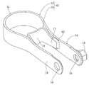
なお、図4に示すように、湾曲部52と一対の連結部54と跨って補強リブ55を設け連結部材50の高剛性化を図ってもよく、この補強リブ55は湾曲部52と一対の連結部54とを成形するプレス成形により同時に形成してもよい。
As shown in FIG. 4, a reinforcing
補強部材70は、連結部材50に固定され連結部材50の剛性を高め補強するものであって、一対の連結部54の対向面に沿って設けられる一対の固定部72と、一対の固定部72を連結する当接部74とを備え、一対の固定部72と当接部74とが略矩形状の1枚の金属板の曲げ加工により一体に形成されている。
The reinforcing
補強部材70は、一対の固定部72の一端部(第2防振ブッシュ側端部)が、連結部材50の一対の連結部54に溶接部60を介して溶接固定され、一対の固定部72の他端部(第1防振ブッシュ側端部)に当接部74が一体に設けられている。当接部74は、連結部材50の湾曲部52の周方向に開口する部分において第1防振ブッシュ20の第1外筒21の外周面に沿う円弧状をなしており、当接部74と湾曲部52との間に第1防振ブッシュ20の第1外筒22が圧入され、第1防振ブッシュ20がブラケット40に保持固定される。
In the reinforcing
なお、図5に示すように、一対の固定部72及び当接部74に一体に設けられた補強部75によって補強部材70の剛性を高めて圧入された第1防振ブッシュ20の保持力を向上させてもよい。
As shown in FIG. 5, the holding force of the first
以上のような本実施形態の防振連結ロッド10のブラケット40では、第1防振ブッシュ20を保持する湾曲部52から径方向外方に突出する連結部54と、この連結部54に沿って設けられた固定部72とが溶接部60によって固定され、連結部材50において第1防振ブッシュ20の第1外筒21と接触する部分や、連結部54と湾曲部52との境界部分近傍を避けて連結部材50に補強部材70を固定する溶接部60が設けられている。そのため、防振連結ロッド10に振動が入力され第1防振ブッシュ20を保持する湾曲部52や補強部材70の当接部74に歪みが生じても、その歪みが溶接部60に集中しにくくなり、ブラケット40の耐久性を大幅に向上させることができる。
In the
しかも、本実施形態では、連結部材50の湾曲部52と補強部材70の当接部74との間に第1防振ブッシュ20が圧入されると、補強部材70には、第2防振ブッシュ30へ向けて連結部材50の連結部54の延びる方向に沿った力が作用することになり、固定部72を連結部54から引き離す方向の力がほとんど作用することがないため、第1防振ブッシュ20の圧入時に溶接部60が破損しにくく、ブラケット40の耐久性を大幅に向上させることができる。
In addition, in the present embodiment, when the first
また、本実施形態では、連結部材50と、補強部材70とが別部材で構成されているため、連結部材50の湾曲部52に対する補強部材70の当接部74の位置を連結部54の延びる方向に沿って変更することで、言い換えれば、補強部材70の当接部74の位置を湾曲部52の中心位置に近接離隔されることで、第1防振ブッシュ20を圧入する際の締め代を調整することができ、第1防振ブッシュ20の保持力を高めることができる。
Further, in this embodiment, since the connecting
更にまた、本実施形態では、ブラケット40を構成する連結部材50及び補強部材70が、略矩形状の1枚の金属板の曲げ加工により成形されているため、金属板の打ち抜き形状を単純化し金属板の打ち抜きロスを抑えることができ、防振連結ロッド100の製造コストを抑えることができる。
Furthermore, in this embodiment, since the connecting
(第2の実施形態)
次に、本発明の第2の実施形態について、図面を参照して説明する。
(Second Embodiment)
Next, a second embodiment of the present invention will be described with reference to the drawings.
本実施形態の防振連結ロッド10では、ブラケット40を構成する連結部材50の湾曲部52にフランジ部53が設けられている点で上記した第1の実施形態と相違する。
The
詳細には、図6に示すように、湾曲部52における第1防振ブッシュ20の軸方向一端部には、径方向内方に向けて突出するフランジ部53が設けられている。フランジ部53には、湾曲部52に圧入された第1防振ブッシュ20の第1外筒21の軸方向一端が当接しており、軸方向一端から第1防振ブッシュ20が脱落するのを防止する。フランジ部53は、湾曲部52の周方向の全域に設けてもよく、また、周方向の一部に設けてもよい。
Specifically, as shown in FIG. 6, a
このようなフランジ部53を形成するには、第1外筒21よりも湾曲部52の軸方向に沿った長さを長く設け、連結部材50の湾曲部52と補強部材70の当接部74との間に第1防振ブッシュ20を圧入した後、第1外筒21よりはみ出た部分を径方向内方へかしめることで、フランジ部53を形成することができる。
In order to form such a
なお、軸方向一端から第1防振ブッシュ20が脱落するのを防止するために、湾曲部52にフランジ部53を設ける場合について説明したが、図7に示すように、第1外筒21の軸方向一端に径方向外方に向けて突出するフランジ部24を設け、連結部材50の湾曲部52と補強部材70の当接部74との間に第1防振ブッシュ20を圧入した後、第1外筒21に設けられたフランジ部24を湾曲部52に当接させてもよい。
In addition, although the case where the
その他の構成は第1の実施形態と同様であり、同様の作用効果が奏される。 Other configurations are the same as those of the first embodiment, and the same functions and effects are achieved.
10…防振連結ロッド 20…第1防振ブッシュ 21…第1外筒
22…第1内筒 23…第1ゴム状弾性体 24…フランジ部
30…第2防振ブッシュ 31…第2外筒 32…第2内筒
33…第2ゴム状弾性体 35…エンジン側ブラケット 36…筒部
40…ブラケット 41…ボルト 50…連結部材
52…湾曲部 53…フランジ部 54…連結部
55…補強リブ 56…ボルト孔 58…ナット
60…溶接部 70…補強部材 72…固定部
74…当接部 75…補強部
DESCRIPTION OF
Claims (3)
前記連結部材は、前記第1防振ブッシュの外周面に沿って設けられる湾曲部と、前記湾曲部の両端部より前記第1防振ブッシュから離間する方向へ延び、前記第2防振ブッシュの軸方向に間隔をあけて設けられる一対の連結部とを備え、前記湾曲部及び前記一対の連結部が1枚の金属板の曲げ加工により形成されてなり、
前記補強部材は、前記一対の連結部に沿って設けられる一対の固定部と、前記一対の固定部を連結し前記第1防振ブッシュの外周面に当接する当接部とを備えることを特徴とするブラケット。 A connection member that connects the first vibration isolation bush and the second vibration isolation bush, and a reinforcing member that is fixed to the connection member;
The connecting member includes a curved portion provided along an outer peripheral surface of the first vibration isolating bush, and extends in a direction away from the first vibration isolating bush from both end portions of the curved portion. A pair of connecting portions provided at intervals in the axial direction, the curved portion and the pair of connecting portions are formed by bending a single metal plate,
The reinforcing member includes a pair of fixing portions provided along the pair of connecting portions, and an abutting portion that connects the pair of fixing portions and contacts an outer peripheral surface of the first vibration isolation bushing. And a bracket.
前記連結部材は、第1防振ブッシュの外周面の少なくとも一部に沿って設けられる湾曲部と、前記湾曲部の両端部より前記第1防振ブッシュから離間する方向へ延び、前記第2防振ブッシュの軸方向に間隔をあけて設けられる一対の連結部とを備え、前記湾曲部及び前記一対の連結部が1枚の金属板の曲げ加工により形成されてなり、
前記補強部材は、前記一対の連結部に沿って設けられる一対の固定部と、前記一対の固定部を連結し前記第1防振ブッシュの外周面に当接する当接部とを備えることを特徴とする防振連結ロッド。 A first anti-vibration bush, a second anti-vibration bush, a connecting member for connecting the first anti-vibration bush and the second anti-vibration bush, and a reinforcing member fixed to the connecting member,
The connecting member includes a curved portion provided along at least a part of the outer peripheral surface of the first vibration isolating bush, and extends in a direction away from the first vibration isolating bush from both ends of the curved portion. A pair of connecting portions provided at intervals in the axial direction of the vibration bush, the curved portion and the pair of connecting portions are formed by bending a single metal plate,
The reinforcing member includes a pair of fixing portions provided along the pair of connecting portions, and an abutting portion that connects the pair of fixing portions and contacts an outer peripheral surface of the first vibration isolation bushing. Anti-vibration connecting rod.
Priority Applications (1)
| Application Number | Priority Date | Filing Date | Title |
|---|---|---|---|
| JP2012098755A JP5959918B2 (en) | 2012-04-24 | 2012-04-24 | Bracket and anti-vibration connecting rod |
Applications Claiming Priority (1)
| Application Number | Priority Date | Filing Date | Title |
|---|---|---|---|
| JP2012098755A JP5959918B2 (en) | 2012-04-24 | 2012-04-24 | Bracket and anti-vibration connecting rod |
Publications (2)
| Publication Number | Publication Date |
|---|---|
| JP2013228002A true JP2013228002A (en) | 2013-11-07 |
| JP5959918B2 JP5959918B2 (en) | 2016-08-02 |
Family
ID=49675824
Family Applications (1)
| Application Number | Title | Priority Date | Filing Date |
|---|---|---|---|
| JP2012098755A Active JP5959918B2 (en) | 2012-04-24 | 2012-04-24 | Bracket and anti-vibration connecting rod |
Country Status (1)
| Country | Link |
|---|---|
| JP (1) | JP5959918B2 (en) |
Cited By (4)
| Publication number | Priority date | Publication date | Assignee | Title |
|---|---|---|---|---|
| US9347517B2 (en) * | 2011-07-13 | 2016-05-24 | Nissan Motor Co., Ltd. | Torque rod |
| JP2016161049A (en) * | 2015-03-02 | 2016-09-05 | 倉敷化工株式会社 | Link bracket |
| CN107963131A (en) * | 2017-12-26 | 2018-04-27 | 重庆小康工业集团股份有限公司 | Torque arm suspension bracket after light-type automobile |
| CN108312823A (en) * | 2018-01-11 | 2018-07-24 | 浙江零跑科技有限公司 | A kind of electronic automobile-used two-stage vibration reduction suspending device |
Citations (6)
| Publication number | Priority date | Publication date | Assignee | Title |
|---|---|---|---|---|
| JPS6252330U (en) * | 1985-09-20 | 1987-04-01 | ||
| JPS62191531U (en) * | 1986-05-28 | 1987-12-05 | ||
| JPH07117428A (en) * | 1993-10-28 | 1995-05-09 | Nissan Motor Co Ltd | Link member of vehicle suspension |
| JP2003206991A (en) * | 2002-01-10 | 2003-07-25 | Tokai Rubber Ind Ltd | Vibration isolating device, fixture used for it and manufacture of vibration isolating device |
| JP2006194370A (en) * | 2005-01-14 | 2006-07-27 | Toyo Tire & Rubber Co Ltd | Vibration-proof device |
| JP2008002615A (en) * | 2006-06-23 | 2008-01-10 | Hosei Brake Ind Ltd | Torque rod |
-
2012
- 2012-04-24 JP JP2012098755A patent/JP5959918B2/en active Active
Patent Citations (6)
| Publication number | Priority date | Publication date | Assignee | Title |
|---|---|---|---|---|
| JPS6252330U (en) * | 1985-09-20 | 1987-04-01 | ||
| JPS62191531U (en) * | 1986-05-28 | 1987-12-05 | ||
| JPH07117428A (en) * | 1993-10-28 | 1995-05-09 | Nissan Motor Co Ltd | Link member of vehicle suspension |
| JP2003206991A (en) * | 2002-01-10 | 2003-07-25 | Tokai Rubber Ind Ltd | Vibration isolating device, fixture used for it and manufacture of vibration isolating device |
| JP2006194370A (en) * | 2005-01-14 | 2006-07-27 | Toyo Tire & Rubber Co Ltd | Vibration-proof device |
| JP2008002615A (en) * | 2006-06-23 | 2008-01-10 | Hosei Brake Ind Ltd | Torque rod |
Cited By (5)
| Publication number | Priority date | Publication date | Assignee | Title |
|---|---|---|---|---|
| US9347517B2 (en) * | 2011-07-13 | 2016-05-24 | Nissan Motor Co., Ltd. | Torque rod |
| JP2016161049A (en) * | 2015-03-02 | 2016-09-05 | 倉敷化工株式会社 | Link bracket |
| CN107963131A (en) * | 2017-12-26 | 2018-04-27 | 重庆小康工业集团股份有限公司 | Torque arm suspension bracket after light-type automobile |
| CN107963131B (en) * | 2017-12-26 | 2024-03-29 | 重庆小康工业集团股份有限公司 | Light-weight rear torsion bar suspension bracket of automobile |
| CN108312823A (en) * | 2018-01-11 | 2018-07-24 | 浙江零跑科技有限公司 | A kind of electronic automobile-used two-stage vibration reduction suspending device |
Also Published As
| Publication number | Publication date |
|---|---|
| JP5959918B2 (en) | 2016-08-02 |
Similar Documents
| Publication | Publication Date | Title |
|---|---|---|
| US9010716B2 (en) | Vibration-damping device | |
| JP5959918B2 (en) | Bracket and anti-vibration connecting rod | |
| JP6532367B2 (en) | Tubular vibration control with bracket | |
| WO2016047395A1 (en) | Tubular antivibration device | |
| WO2014141929A1 (en) | Antivibration device | |
| JP6418980B2 (en) | Link bracket | |
| JP2005282732A (en) | Engine mount | |
| JP2003294084A (en) | Vibration-resistant bush | |
| JP5628634B2 (en) | Torque rod and its mounting structure | |
| WO2011036890A1 (en) | Torque rod | |
| JP2013177924A (en) | Bracket and vibration-isolating connecting rod | |
| JP5207524B2 (en) | Torque rod mounting structure | |
| JP2014145410A (en) | Suspension bush | |
| JP2008002615A (en) | Torque rod | |
| JP5951468B2 (en) | Anti-vibration bush | |
| JP2018070039A (en) | Vehicular-member mounting structure | |
| WO2019131511A1 (en) | Vibration isolating device | |
| JP2009085315A (en) | Cylindrical type antivibration device | |
| JP2010038195A (en) | Torque rod and manufacturing method therefor | |
| JP2023170298A (en) | Antivibration device | |
| JP3937352B2 (en) | Vibration isolator | |
| JP2013221595A (en) | Bearing structure and manufacturing method | |
| JP2014201191A (en) | Suspension arm mounting structure | |
| JP2009216135A (en) | Automobile cylindrical vibration isolator | |
| JP5184287B2 (en) | Anti-vibration bush |
Legal Events
| Date | Code | Title | Description |
|---|---|---|---|
| A621 | Written request for application examination |
Free format text: JAPANESE INTERMEDIATE CODE: A621 Effective date: 20150407 |
|
| A977 | Report on retrieval |
Free format text: JAPANESE INTERMEDIATE CODE: A971007 Effective date: 20160115 |
|
| A131 | Notification of reasons for refusal |
Free format text: JAPANESE INTERMEDIATE CODE: A131 Effective date: 20160119 |
|
| A521 | Request for written amendment filed |
Free format text: JAPANESE INTERMEDIATE CODE: A523 Effective date: 20160318 |
|
| TRDD | Decision of grant or rejection written | ||
| A01 | Written decision to grant a patent or to grant a registration (utility model) |
Free format text: JAPANESE INTERMEDIATE CODE: A01 Effective date: 20160607 |
|
| A61 | First payment of annual fees (during grant procedure) |
Free format text: JAPANESE INTERMEDIATE CODE: A61 Effective date: 20160622 |
|
| R150 | Certificate of patent or registration of utility model |
Ref document number: 5959918 Country of ref document: JP Free format text: JAPANESE INTERMEDIATE CODE: R150 |
|
| S531 | Written request for registration of change of domicile |
Free format text: JAPANESE INTERMEDIATE CODE: R313531 |
|
| R350 | Written notification of registration of transfer |
Free format text: JAPANESE INTERMEDIATE CODE: R350 |
|
| S533 | Written request for registration of change of name |
Free format text: JAPANESE INTERMEDIATE CODE: R313533 |
|
| R350 | Written notification of registration of transfer |
Free format text: JAPANESE INTERMEDIATE CODE: R350 |
|
| R250 | Receipt of annual fees |
Free format text: JAPANESE INTERMEDIATE CODE: R250 |
|
| R250 | Receipt of annual fees |
Free format text: JAPANESE INTERMEDIATE CODE: R250 |
|
| R250 | Receipt of annual fees |
Free format text: JAPANESE INTERMEDIATE CODE: R250 |
|
| R250 | Receipt of annual fees |
Free format text: JAPANESE INTERMEDIATE CODE: R250 |
|
| R250 | Receipt of annual fees |
Free format text: JAPANESE INTERMEDIATE CODE: R250 |