JP2013222991A - Radio communication system, radio communication method, and radio terminal device - Google Patents
Radio communication system, radio communication method, and radio terminal device Download PDFInfo
- Publication number
- JP2013222991A JP2013222991A JP2012091383A JP2012091383A JP2013222991A JP 2013222991 A JP2013222991 A JP 2013222991A JP 2012091383 A JP2012091383 A JP 2012091383A JP 2012091383 A JP2012091383 A JP 2012091383A JP 2013222991 A JP2013222991 A JP 2013222991A
- Authority
- JP
- Japan
- Prior art keywords
- wireless
- wireless communication
- terminal device
- setting information
- ssid
- Prior art date
- Legal status (The legal status is an assumption and is not a legal conclusion. Google has not performed a legal analysis and makes no representation as to the accuracy of the status listed.)
- Pending
Links
Images


Classifications
-
- H—ELECTRICITY
- H04—ELECTRIC COMMUNICATION TECHNIQUE
- H04W—WIRELESS COMMUNICATION NETWORKS
- H04W12/00—Security arrangements; Authentication; Protecting privacy or anonymity
- H04W12/06—Authentication
-
- H—ELECTRICITY
- H04—ELECTRIC COMMUNICATION TECHNIQUE
- H04W—WIRELESS COMMUNICATION NETWORKS
- H04W48/00—Access restriction; Network selection; Access point selection
- H04W48/08—Access restriction or access information delivery, e.g. discovery data delivery
- H04W48/10—Access restriction or access information delivery, e.g. discovery data delivery using broadcasted information
-
- H—ELECTRICITY
- H04—ELECTRIC COMMUNICATION TECHNIQUE
- H04W—WIRELESS COMMUNICATION NETWORKS
- H04W48/00—Access restriction; Network selection; Access point selection
- H04W48/08—Access restriction or access information delivery, e.g. discovery data delivery
- H04W48/12—Access restriction or access information delivery, e.g. discovery data delivery using downlink control channel
-
- H—ELECTRICITY
- H04—ELECTRIC COMMUNICATION TECHNIQUE
- H04W—WIRELESS COMMUNICATION NETWORKS
- H04W76/00—Connection management
- H04W76/10—Connection setup
- H04W76/11—Allocation or use of connection identifiers
-
- H—ELECTRICITY
- H04—ELECTRIC COMMUNICATION TECHNIQUE
- H04L—TRANSMISSION OF DIGITAL INFORMATION, e.g. TELEGRAPHIC COMMUNICATION
- H04L41/00—Arrangements for maintenance, administration or management of data switching networks, e.g. of packet switching networks
- H04L41/08—Configuration management of networks or network elements
- H04L41/085—Retrieval of network configuration; Tracking network configuration history
- H04L41/0853—Retrieval of network configuration; Tracking network configuration history by actively collecting configuration information or by backing up configuration information
-
- H—ELECTRICITY
- H04—ELECTRIC COMMUNICATION TECHNIQUE
- H04W—WIRELESS COMMUNICATION NETWORKS
- H04W48/00—Access restriction; Network selection; Access point selection
- H04W48/16—Discovering, processing access restriction or access information
-
- H—ELECTRICITY
- H04—ELECTRIC COMMUNICATION TECHNIQUE
- H04W—WIRELESS COMMUNICATION NETWORKS
- H04W8/00—Network data management
- H04W8/005—Discovery of network devices, e.g. terminals
-
- H—ELECTRICITY
- H04—ELECTRIC COMMUNICATION TECHNIQUE
- H04W—WIRELESS COMMUNICATION NETWORKS
- H04W84/00—Network topologies
- H04W84/02—Hierarchically pre-organised networks, e.g. paging networks, cellular networks, WLAN [Wireless Local Area Network] or WLL [Wireless Local Loop]
- H04W84/10—Small scale networks; Flat hierarchical networks
- H04W84/12—WLAN [Wireless Local Area Networks]
Abstract
Description
本発明は、無線通信システム、無線通信方法及び無線端末装置に関する。 The present invention relates to a wireless communication system, a wireless communication method, and a wireless terminal device.
電子情報機器同士の無線ネットワーク接続については、従来から様々な接続方法が提案されている。たとえば、プロジェクタとPCを無線通信により接続することによって、PCからの映像を電子情報ボード等の大型ディスプレイに映し出すことができる。 Conventionally, various connection methods have been proposed for wireless network connection between electronic information devices. For example, by connecting a projector and a PC by wireless communication, an image from the PC can be displayed on a large display such as an electronic information board.
無線ネットワークでの通信を行うためには、端末同士で無線ネットワークの設定を正しく行う必要がある。しかし、無線の設定にはIPアドレス、サブネットマスク、認証方式、暗号方式、暗号方式に対応した暗号鍵等のさまざまな設定があり、知識の無いユーザにとっては正しい設定を行うことが難しい。そこで、上記の無線ネットワークの設定を簡単な操作で自動的に行う技術が考えられ、既に知られている。 In order to communicate on a wireless network, it is necessary to correctly set the wireless network between terminals. However, wireless settings include various settings such as an IP address, a subnet mask, an authentication method, an encryption method, and an encryption key corresponding to the encryption method, and it is difficult for a user without knowledge to make a correct setting. Therefore, a technique for automatically setting the wireless network with a simple operation is conceivable and already known.
特許文献1及び特許文献2には、無線ネットワークの設定を簡単な操作で行う目的で、自身の端末の無線LAN(Local Area Network)のIPv4のIPアドレスと端末識別子(たとえば、端末の名前)からなるSSID(Service Set Identifier)を生成し、無線ビーコンに含めて送信する無線端末装置や無線通信システムが開示されている。
In
しかし、今までの無線ネットワークの設定を簡単な操作で自動的に行う装置では、ビーコンに含まれるSSIDに端末のIPアドレスを含めていた。このため、IPv4(Internet Protocol version4)以外の無線の通信プロトコルを採用している場合には、この方式が使えないという課題があった。 However, in a device that automatically sets up a wireless network with a simple operation so far, the IP address of the terminal is included in the SSID included in the beacon. For this reason, there is a problem that this method cannot be used when a wireless communication protocol other than IPv4 (Internet Protocol version 4) is adopted.
具体的に説明すると、無線端末装置の一方(接続される端末)は一定の間隔で、自分自身の存在を知らせるためにビーコンと呼ばれる無線信号を送信し続ける。このビーコンには無線ネットワークを識別する32バイトのSSIDが含まれている。今までの方式では、通信相手に無線ネットワークの設定情報を知らせるために、SSIDに自身の端末の無線LANのIPv4のIPアドレスと無線端末装置を識別する領域を含めていた。そして、無線端末装置のもう一方(接続する端末)は上記SSIDに含まれている情報から通信相手のIPアドレスを取得し、通信を行っていた。 More specifically, one of the wireless terminal devices (connected terminal) continues to transmit a wireless signal called a beacon to notify the presence of itself at a constant interval. This beacon includes a 32-byte SSID that identifies the wireless network. In the conventional method, in order to notify the communication partner of the setting information of the wireless network, the SSID includes an area for identifying the wireless terminal IPv4 IP address and the wireless terminal device. Then, the other of the wireless terminal devices (terminal to be connected) acquires the communication partner's IP address from the information included in the SSID and performs communication.
SSIDには一般的にASCII文字列しか含めることができないため、IPアドレスを16進数の文字列に変換し8バイトの領域に割り当て、残りの24バイトを、無線端末装置を識別する領域に割り当てていた。IPv6(Internet Protocol version6)ではIPv4の4倍の32バイトの領域が必要になるため、他の情報を入れる領域が割り当てられなくなるという課題があった。 Since an SSID can generally contain only an ASCII character string, an IP address is converted into a hexadecimal character string and assigned to an 8-byte area, and the remaining 24 bytes are assigned to an area for identifying a wireless terminal device. It was. In IPv6 (Internet Protocol version 6), an area of 32 bytes, which is four times as large as IPv4, is required, and there is a problem that an area for storing other information cannot be allocated.
たとえば、特許文献1及び特許文献2においても、無線の通信プロトコルがIPv6のときにこれらの特許文献にて開示された方式では、SSIDにIPv6以外の他の情報を入れる領域が割り当てられなくなり、無線ネットワークの設定を簡単な操作で自動的に行うことはできない。
For example, also in
このように、これまでの技術では、無線通信のプロトコルがIPv6のときにビット数が大きくなり無線通信ができないという課題を有する。また、これまでの技術では、無線通信を確立する際に交換する無線設定情報が多すぎるため、無線通信の接続を確立するまでに時間がかかるという課題を有する。更に、特に無線通信においては、通信パケットが通信相手の端末装置まで届かずに通信の接続の確立が失敗しやすいという課題を有する。 As described above, the conventional techniques have a problem that the number of bits becomes large and the wireless communication cannot be performed when the wireless communication protocol is IPv6. In addition, the conventional technology has a problem that it takes time to establish a wireless communication connection because too much wireless setting information is exchanged when establishing wireless communication. Furthermore, particularly in wireless communication, there is a problem that the establishment of communication connection is likely to fail because the communication packet does not reach the terminal device of the communication partner.
上記課題に対して、本発明の目的とするところは、IPv6のプロトコルだけでなく、IPv4以外のプロトコルにおいても無線ネットワークの設定を容易に行うことが可能な無線通信システム、無線通信方法及び無線端末装置を提供することにある。 In view of the above problems, an object of the present invention is to provide a wireless communication system, a wireless communication method, and a wireless terminal capable of easily setting a wireless network not only with the IPv6 protocol but also with a protocol other than IPv4. To provide an apparatus.
上記課題を解決するために、本発明のある観点によれば、
接続される無線端末装置と接続する無線端末装置とが無線通信可能な無線通信システムであって、
前記接続される無線端末装置は、
前記接続する無線端末装置に保持される第2の無線設定情報との無線通信における共通情報として予め定められた第1の無線設定情報を設定する第1のネットワーク制御部と、
前記無線通信における固有の識別情報を含むSSIDを生成する生成部と、
前記生成されたSSIDを含むビーコンを送信する第1の無線通信部と、を備え、
前記接続する無線端末装置は、
前記ビーコンを受信する第2の無線通信部と、
前記ビーコンから前記SSIDを抽出し、該抽出されたSSIDに含まれる前記固有の識別情報を抽出する抽出部と、
前記第2の無線設定情報を保持する第2の保持部と、
前記第2の無線設定情報を設定し、前記抽出された固有の識別情報と前記第2の無線設定情報とを用いて前記接続される無線端末装置との無線通信の接続を確立する第2のネットワーク制御部と、
を備えることを特徴とする無線通信システムが提供される。
In order to solve the above problems, according to one aspect of the present invention,
A wireless communication system capable of wireless communication with a connected wireless terminal device and a wireless terminal device connected thereto,
The connected wireless terminal device is:
A first network control unit configured to set first wireless setting information predetermined as common information in wireless communication with second wireless setting information held in the connected wireless terminal device;
A generating unit that generates an SSID including unique identification information in the wireless communication;
A first wireless communication unit that transmits a beacon including the generated SSID,
The wireless terminal device to be connected is
A second wireless communication unit that receives the beacon;
An extraction unit that extracts the SSID from the beacon and extracts the unique identification information included in the extracted SSID;
A second holding unit for holding the second wireless setting information;
The second wireless setting information is set, and a wireless communication connection with the connected wireless terminal device is established using the extracted unique identification information and the second wireless setting information. A network controller;
A wireless communication system is provided.
以上説明したように、本発明によれば、IPv6のプロトコルだけでなく、IPv4以外のプロトコルにおいても無線ネットワークの設定を容易に行うことができる。 As described above, according to the present invention, not only the IPv6 protocol but also a protocol other than IPv4 can easily set a wireless network.
以下に添付図面を参照しながら、本発明の実施形態について説明する。なお、本明細書及び図面において、実質的に同一の機能構成を有する構成要素については、同一の符号を付することにより重複説明を省略する。 Embodiments of the present invention will be described below with reference to the accompanying drawings. In addition, in this specification and drawing, about the component which has the substantially same function structure, duplication description is abbreviate | omitted by attaching | subjecting the same code | symbol.
以下に説明する一実施形態に係る無線通信システムは、接続される無線端末装置と接続する無線端末装置とが無線通信することが可能なシステムである。この無線通信システムでは、IPアドレス/サブネットマスク等の無線設定情報については、無線端末装置の一方(接続される無線端末装置)では予め決められた番号を使用し、ビーコンに含まれるSSIDには、無線端末装置同士が重複しない各無線端末装置に固有の端末識別子のみ含める。よって、無線通信の接続を確立する際、本実施形態に係る無線通信システムでは、送信ビーコンにSSIDの情報が含まれる。これにより、本実施形態に係る無線通信システムは、簡単な操作で無線ネットワークの設定を自動的に行うことが可能な無線通信システムを提供することができる。 A wireless communication system according to an embodiment described below is a system that enables wireless communication with a connected wireless terminal device and a wireless terminal device connected thereto. In this wireless communication system, for wireless setting information such as an IP address / subnet mask, one of the wireless terminal devices (connected wireless terminal device) uses a predetermined number, and the SSID included in the beacon includes: Only terminal identifiers unique to each wireless terminal apparatus that do not overlap each other are included. Therefore, when establishing a wireless communication connection, the transmission beacon includes SSID information in the wireless communication system according to the present embodiment. Thereby, the radio | wireless communications system which concerns on this embodiment can provide the radio | wireless communications system which can set a wireless network automatically by simple operation.
また、本実施形態に係る無線通信システムは、たとえIPv6のようにアドレス情報がIPv4より長くなった場合でも、SSID内の情報にIPアドレスを含める必要がない。このため、無線の通信プロトコルの方式がIPv4及びIPv6のいずれの場合であっても同様に接続できる。 Further, the wireless communication system according to the present embodiment does not need to include the IP address in the information in the SSID even when the address information is longer than IPv4 as in IPv6. For this reason, connection is possible in the same way regardless of whether the wireless communication protocol is IPv4 or IPv6.
接続される無線端末装置側で予め設定される第1の無線設定情報、及び接続する無線端末装置側で予め設定される第2の無線設定情報は共通情報として予め定められ、第1の保持部及び第2の保持部にそれぞれ保持されている。ここで、第1の無線設定情報と第2の無線設定情報とが共通情報であるとは、第1の無線設定情報と第2の無線設定情報とが同一である場合に限られず、例えば、第1の無線設定情報に所望の変換を施すことによって第2の無線設定情報と同一の値を得られる場合も含む。 The first wireless setting information set in advance on the connected wireless terminal device side and the second wireless setting information set in advance on the connected wireless terminal device side are predetermined as common information, and the first holding unit And the second holding portion. Here, the fact that the first wireless setting information and the second wireless setting information are common information is not limited to the case where the first wireless setting information and the second wireless setting information are the same, for example, This includes the case where the same value as the second wireless setting information can be obtained by performing desired conversion on the first wireless setting information.
このため、無線通信の接続時に接続される無線端末装置と接続する無線端末装置とで情報の交換すべき無線設定情報が少なくなり、情報の交換に費やしていた時間を減らすことができる。これにより、接続までの時間が短く、かつユーザの利便性が高いシステムを構築することができる。更に、無線通信において通信パケットが通信相手の無線端末装置まで届かずに接続の確立に失敗する確率が低いシステムを構築することができる。以下、本実施形態に係る無線通信システムについて詳細に説明する。 For this reason, the wireless setting information to be exchanged between the wireless terminal device connected at the time of wireless communication connection and the wireless terminal device to be connected is reduced, and the time spent for exchanging information can be reduced. As a result, it is possible to construct a system that is short in connection time and high in user convenience. Furthermore, it is possible to construct a system with a low probability that a communication packet does not reach the wireless terminal device of the communication partner in wireless communication and connection establishment fails. Hereinafter, the radio communication system according to the present embodiment will be described in detail.
[無線通信システムの全体構成]
(無線通信システムのハードウエア構成)
まず、本発明の一実施形態に係る無線通信システムのハードウエア構成について、図1を参照しながら説明する。図1は、本発明の一実施形態に係る無線通信システムのハードウエア構成図である。
[Overall configuration of wireless communication system]
(Hardware configuration of wireless communication system)
First, a hardware configuration of a wireless communication system according to an embodiment of the present invention will be described with reference to FIG. FIG. 1 is a hardware configuration diagram of a wireless communication system according to an embodiment of the present invention.
本実施形態に係る無線通信システム1は、無線ネットワーク機能を備えたプロジェクタ100と無線ネットワーク機能を備えたPC200(たとえばノートPC)とが無線ネットワークにより接続されている。本実施形態に係る無線通信システム1では、プロジェクタ100は接続される無線端末装置の一例であり、PC200は接続する無線端末装置の一例であるが、接続される無線端末装置及び接続する無線端末装置はこれに限られない。たとえば、本実施形態に係る無線通信システム1は、電子会議システムにも応用できる。この場合、接続される無線端末装置は電子掲示板、接続する無線端末装置はPCとすることができる。このように、本実施形態に係る無線通信システム1によって電子掲示板とPCとを直接、高速に接続したり、それ以外の表示装置とPCとを直接高速に接続したりすることができる。その他、接続される無線端末装置をプリンタ、接続する無線端末装置をPCとし、本無線通信システム1を使用してPCが接続相手のプリンタを迅速に見つけて、高速にプリント処理することができる。
In the
プロジェクタ100は、CPU10、第1の記憶部12、第1の操作入力部14、第1の無線通信部16、第1の映像出力部18を有している。CPU10は、プロジェクタ100の全体の制御を行う。例えば、CPU10の全体制御は、第1の記憶部12に格納されたプログラムに従って動作することによって実現されうる。このプログラムは、記憶媒体に格納して提供され、図示しないドライバを介して第1の記憶部12に読み込まれるものであってもよく、また、ネットワークからダウンロードされて第1の記憶部12に格納されるものであってもよい。第1の記憶部12は、例えば、RAM(Random Access Memory)またはROM(Read Only Memory)、HDD(Hard Disk Drive)として実現されうる。
The
第1の操作入力部14は、ユーザ操作に応じて情報を入力する。第1の無線通信部16は、PC200の第2の無線通信部26と無線通信により情報を送受信する。第1の無線通信部16は、後述するSSID生成部によって生成されたSSIDを含むビーコンを送信する。第1の映像出力部18は、PC200から送信された映像をスクリーン等の表示装置に投影する。
The first
PC200は、CPU20、第2の記憶部22、第2の操作入力部24、第2の無線通信部26、第2の映像出力部28を有している。CPU20は、PC200の全体の制御を行う。例えば、CPU20の全体制御は、第2の記憶部22に格納されたプログラムに従って動作することによって実現されうる。このプログラムは、記憶媒体に格納して提供され、図示しないドライバを介して第2の記憶部22に読み込まれるものであってもよく、また、ネットワークからダウンロードされて第2の記憶部22に格納されるものであってもよい。第1の記憶部12は、RAM(Random Access Memory)またはROM(Read Only Memory)、HDD(Hard Disk Drive)として実現されうる。
The
第2の操作入力部24は、ユーザ操作に応じて情報を入力する。第2の操作入力部24は、タッチパネルやマウス、キーボード等により実現されうる。
The second
第2の無線通信部26は、第1の無線通信部16からビーコンを受信する。また、第2の無線通信部26は、第1の無線通信部16と情報を送受信する。第2の映像出力部28は、PC200が保持する映像を液晶ディスプレイ等に表示する。
(無線通信システムのソフトウエア構成)
次に、本発明の一実施形態に係る無線通信システムのソフトウエア構成について、図2を参照しながら説明する。図2は、本発明の一実施形態に係る無線通信システムのソフトウエア構成図である。プロジェクタ100は、第1のユーザ操作部30、第1の無線設定保持部32、第1のネットワーク制御部34、端末識別子生成部36、SSID生成部38、第1の映像表示部40を有している。
The second
(Software configuration of wireless communication system)
Next, the software configuration of the wireless communication system according to the embodiment of the present invention will be described with reference to FIG. FIG. 2 is a software configuration diagram of the wireless communication system according to the embodiment of the present invention. The
第1のユーザ操作部30は、ユーザによる入力操作を可能とする。
The first
第1の無線設定保持部32は、予め設定された無線通信における共通情報を保持する。第1の無線設定保持部32は、PC200に保持される第2の無線設定情報と共通情報として予め設定された第1の無線設定情報を保持する第1の保持部に相当する。
The first wireless
PC200の立ち上げ時、第1のネットワーク制御部34は、その時点での無線設定値を無線設定情報(本実施形態では、無線通信における共通情報)として設定する。第1のネットワーク制御部34は、無線通信の接続時、無線設定情報が第1の無線設定情報と異なる値に設定されている場合、第1の無線設定情報に設定を変更する。
When the
端末識別子生成部36は、無線通信における固有の識別情報を生成する。例えば、端末識別子生成部36は、固有の識別情報として、無線LANにおけるMAC(Media Access Control address)アドレス、そのMACアドレスを更に変換した数値、プロジェクタ100の製造番号、プロジェクタ100の製造番号を更に変換した数値、乱数等を利用することができる。なお、本実施形態における固有の識別情報は、プロジェクタ100との無線通信が可能な空間において実質的に固有な識別情報であればよい。つまり、ここでの固有の識別情報は、識別情報が異なる、もしくは同値になる可能性が極端に低く、使用上の問題にはならない程度に実質的に固有な識別情報であればよい。
The terminal
SSID生成部38は、端末識別子生成部36により生成された固有の識別情報を含むSSIDを生成する。端末識別子生成部36及びSSID生成部38は、無線通信における固有の識別情報を含むSSIDを生成する生成部に相当する。
The
SSIDにIPアドレスを含めると、無線通信のプロトコルがIPv6に設定されたとき、前述の通り、IPv6はIPv4よりアドレス数が多いため、IPv6のアドレスをSSIDに入れようとしても、SSIDは最大32バイトまでしか許容しないため、IPv6のアドレス以外の情報をSSIDに含ませることができなくなる。よって、SSIDにIPアドレスを含める無線通信方式は、無線通信のプロトコルがIPv6に設定されたとき適用できない。 When the IP address is included in the SSID, when the wireless communication protocol is set to IPv6, as described above, since IPv6 has more addresses than IPv4, even if an IPv6 address is tried to be included in the SSID, the SSID is a maximum of 32 bytes. Therefore, information other than the IPv6 address cannot be included in the SSID. Therefore, the wireless communication method including the IP address in the SSID cannot be applied when the wireless communication protocol is set to IPv6.
一方、本実施形態では、SSIDを生成する際、SSIDにIPアドレスを含めない。よって、本実施形態では、IPv4のアドレスとIPv6のIPアドレスとが混在して構成される現状においても、IPアドレスがIPv6のアドレスのみで構成される将来においても、先行技術の課題を解消したシステムを構築することができる。なお、SSIDは、IEEE802.11シリーズの無線LANにおけるネットワークの識別子を含む。SSID生成については後程詳細を説明する。 On the other hand, in this embodiment, when generating the SSID, the IP address is not included in the SSID. Therefore, in the present embodiment, a system that solves the problems of the prior art even in the present situation where the IPv4 address and the IPv6 IP address are mixed and in the future where the IP address is composed only of the IPv6 address. Can be built. The SSID includes a network identifier in the IEEE802.11 series wireless LAN. Details of SSID generation will be described later.
第1の映像表示部40は、プロジェクタ100の識別情報、その他の映像を表示する。第1の映像表示部40は、複数のプロジェクタ100から一のプロジェクタ100を選択するための選択情報を表示する第1の表示部に相当する。第1の表示部は、プロジェクタ100の選択情報として、生成されたSSIDに設定された情報の全部又は一部を表示してもよい。
The first
PC200は、第2のユーザ操作部50、第2の無線設定保持部52、第2のネットワーク制御部54、端末識別子抽出部56、SSID抽出部58、第2の映像表示部60を有している。第2のユーザ操作部50は、ユーザによる入力操作を可能とする。
The
第2の無線設定保持部52は、予め設定された無線通信における共通情報を保持する。第2の無線設定保持部52は、プロジェクタ100に保持される第1の無線設定情報と共通情報として予め設定された第2の無線設定情報を保持する第2の保持部に相当する。
The second wireless setting holding
第2のネットワーク制御部54は、識別された固有の識別情報と第2の無線設定情報を用いてプロジェクタ100との無線通信の接続を確立する。PC200の立ち上げ時、第2のネットワーク制御部54は、その時点での無線設定値を無線設定情報として設定する。第2のネットワーク制御部54は、無線通信の接続時、無線設定情報が第2の無線設定情報と異なる値に設定されている場合、第2の無線設定情報に設定を変更する。
The second
SSID抽出部58及び端末識別子抽出部56は、ビーコンからSSIDを抽出し、その抽出されたSSIDに含まれる固有の識別情報を抽出する抽出部に相当する。
The
第2の映像表示部60は、SSIDに含まれる無線通信における固有の識別情報の全部又は一部を表示する第2の表示部に相当する。無線通信における固有の識別情報は、プロジェクタ100に関する固有の識別情報である。例えば、第2の映像表示部60は、リスト形式に複数の固有の識別情報を表示する。第2の映像表示部60は、その他の映像を表示してもよい。
The second video display unit 60 corresponds to a second display unit that displays all or part of unique identification information in wireless communication included in the SSID. The unique identification information in the wireless communication is unique identification information regarding the
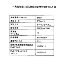
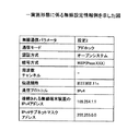
[無線設定情報]
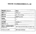
第1の無線設定保持部32及び第2の無線設定保持部52は、共通情報となる第1の無線設定情報及び第2の無線設定情報として、無線通信において共通情報をそれぞれ保持する。図3〜図5は、第1の無線設定情報及び第2の無線設定情報の一例である。
[Wireless setting information]
The first wireless
図3〜図5では、第1の無線設定保持部32は、無線の通信モード、認証方式、暗号方式、無線の通信プロトコル及び接続される無線端末装置のIP(Internet Protoco)アドレスを含んだ第1の無線設定情報を保持する。
3 to 5, the first wireless
第2の無線設定保持部52は、第1の無線設定情報に対応する無線の通信モード、認証方式、暗号方式、無線の通信プロトコル及び接続される無線端末装置のIPアドレスを含んだ第2の無線設定情報を保持する。
The second wireless setting holding
無線の通信モードとしては、アクセスポイントを介さずに無線通信を行うアドホックモードまたはアクセスポイントを介して無線通信を行うインフラストラクチャモードのいずれかを設定することができる。 As the wireless communication mode, either an ad hoc mode in which wireless communication is performed without using an access point or an infrastructure mode in which wireless communication is performed through an access point can be set.
認証方式及び暗号方式についても、様々な公知の技術を採用することができる。例えば、暗号方式としては、WEP(Wired Equivalent Privacy)やWPS(Wi−Fi Protected Setup)が一例として挙げられる。第1の無線通信部16は、生成後のSSIDの文字列を暗号化する。第2の無線通信部26は、ビーコンに含まれるSSIDを復号する。
Various known techniques can be employed for the authentication method and the encryption method. For example, as an encryption method, WEP (Wired Equivalent Privacy) and WPS (Wi-Fi Protected Setup) are mentioned as examples. The first
無線の通信プロトコルは、IPv4であってもIPv6であってもその他の独自のプロトコルであってもよい。図3及び図4には、無線の通信プロトコルがIPv4の場合、図5には、無線の通信プロトコルがIPv6の場合が示されている。無線の通信プロトコルがIPv4の場合、接続される無線端末装置のIPアドレスとして、無線のIPv4(Internet Protocol version4)アドレスと無線のIPv4サブネットマスクアドレスを設定する。 The wireless communication protocol may be IPv4, IPv6, or another unique protocol. 3 and 4 show a case where the wireless communication protocol is IPv4, and FIG. 5 shows a case where the wireless communication protocol is IPv6. When the wireless communication protocol is IPv4, a wireless IPv4 (Internet Protocol version 4) address and a wireless IPv4 subnet mask address are set as the IP address of the connected wireless terminal device.
接続される無線端末装置の通信プロトコルがIPv6の場合、無線のIPアドレスとして、無線のIPv6(Internet Protocol version6)アドレスと無線のIPv6アドレスプレフィックスとを設定する。IPv4アドレスとIPv4サブネットマスクアドレスは対になって使用され、互いに対応した値をもっている必要がある。IPv6アドレスとIPv6プレフィックスも同様に互いに対応した値をもっている必要がある。 When the communication protocol of the connected wireless terminal device is IPv6, a wireless IPv6 (Internet Protocol version 6) address and a wireless IPv6 address prefix are set as the wireless IP address. The IPv4 address and the IPv4 subnet mask address are used as a pair and need to have values corresponding to each other. Similarly, the IPv6 address and the IPv6 prefix need to have values corresponding to each other.
無線設定情報としては、これらの無線通信パラメータの他、周波数チャンネルや伝送規格を含んでもよい。伝送規格には、IEEE802の種別を特定する。周波数チャンネルには、予め定められた値を設定してもよいし、走査して得られたユーザ指定の周波数チャンネルの値を設定してもよい。図3では、周波数チャンネルとして固定値が設定されている。図4では、走査して得られたユーザ指定の周波数チャンネルが設定されている。チャンネルを固定化しないことにより、空いている周波数帯域を柔軟に使用することができるというメリットがある。 The wireless setting information may include frequency channels and transmission standards in addition to these wireless communication parameters. The transmission standard specifies the type of IEEE802. A predetermined value may be set for the frequency channel, or a user-specified frequency channel value obtained by scanning may be set. In FIG. 3, a fixed value is set as the frequency channel. In FIG. 4, a user-specified frequency channel obtained by scanning is set. By not fixing the channel, there is an advantage that an available frequency band can be flexibly used.
本実施形態では、第2の無線設定情報は第1の無線設定情報と同一であるが、対応していれば第2の無線設定情報は第1の無線設定情報と必ずしも同一でなくてもよい。たとえば、本実施形態では、無線ネットワークで使用する無線設定情報(無線通信パラメータ)としてPC200で保持される第2の無線設定情報とプロジェクタ100で保持される第1の無線設定情報とが共通情報になるように予め設定され、かつ第2の無線設定情報と第1の無線設定情報との対応関係が予め通知されていればよい。無線通信パラメータの集まりは、1種類であるとは限らず、2種類以上設定されていてもよい。
In the present embodiment, the second wireless setting information is the same as the first wireless setting information, but the second wireless setting information may not necessarily be the same as the first wireless setting information as long as it corresponds. . For example, in the present embodiment, the second wireless setting information held by the
PC200に電源を投入したとき、第2のネットワーク制御部54は、その時点での無線設定値を無線設定情報として設定する。無線通信の接続時、PC200に設定された無線設定情報が第2の無線設定情報と異なる場合、第2のネットワーク制御部54は、第2の無線設定情報に設定を変更する。
When the
同様に、プロジェクタ100に電源を投入したとき、第1のネットワーク制御部34は、その時点での無線設定値を設定する。無線通信の接続時、プロジェクタ100に設定された無線設定情報が第1の無線設定情報と異なる場合、第1のネットワーク制御部34は、第1の無線設定情報に設定を変更する。
Similarly, when the
これまでの通信方式では、IPアドレスは固定値ではなく、どのIPアドレスが割り当てられるか通信相手の機器は知り得ない。そのため、SSIDにIPアドレスを含めることにより、割り当てられたIPアドレスを相手に知らせるようになっている。よって、これまでの通信方式では、無線通信の接続を確立する際に、これらの無線通信パラメータの値をプロジェクタ100とPC200との間で交換しなければならない。
In the conventional communication method, the IP address is not a fixed value, and the communication partner device cannot know which IP address is assigned. For this reason, the IP address is included in the SSID so as to notify the other party of the assigned IP address. Therefore, in the conventional communication method, the values of these wireless communication parameters must be exchanged between the
一方、本実施形態では、以上のように、無線通信における共有の情報を第1の無線設定情報と第2の無線設定情報として予め設定され、プロジェクタ100とPC200とがそれぞれ予め保持している。このため、無線通信接続時にこれらの情報を何らの情報交換なく自動で設定することができる。このため、無線通信接続までの時間を顕著に短縮することができる。また、無線通信において通信パケットが通信相手の無線端末装置まで届かずに接続の確立に失敗する確率が低いシステムを構築することができる。
On the other hand, in the present embodiment, as described above, shared information in wireless communication is set in advance as first wireless setting information and second wireless setting information, and the
[端末識別子の生成方法]
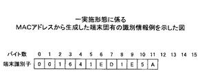
次に、端末識別子生成部36により生成される端末識別子(無線通信における固有の識別情報)の一例について、図6〜図9を参照しながら説明する。
[Terminal identifier generation method]
Next, an example of a terminal identifier (unique identification information in wireless communication) generated by the terminal
図6及び図7は、MACアドレスを使用した端末識別子の生成方法の一例である。図6の端末識別子の生成方法では、MACアドレスをASCIIコードで表す。これにより、端末識別子「001641ED1E5A」が生成される。図7の端末識別子の生成方法では、MACアドレスを元にMACアドレスに何らかの変換処理を加えて端末識別子を生成する。図7では、図6にて示したMACアドレス中の「A」と「0」とを入れ替え、「B」と「0」とを入れ替えるというようにアルファベットの順番と数字を入れ替えている。これにより、端末識別子「AABFDB54B5E0」が生成される。MACアドレスの値を変換方法はどんな方法でもよいが、変換方法は無線接続を行う機器間で予め定められている。 6 and 7 show an example of a method for generating a terminal identifier using a MAC address. In the terminal identifier generation method of FIG. 6, the MAC address is represented by an ASCII code. As a result, the terminal identifier “001641ED1E5A” is generated. In the terminal identifier generation method of FIG. 7, a terminal identifier is generated by adding some conversion processing to the MAC address based on the MAC address. In FIG. 7, the alphabetical order and the numbers are exchanged such that “A” and “0” in the MAC address shown in FIG. 6 are exchanged, and “B” and “0” are exchanged. As a result, the terminal identifier “AABFDB54B5E0” is generated. Any method may be used to convert the MAC address value, but the conversion method is predetermined between devices that perform wireless connection.
プロジェクタ100の製造番号を使用して端末識別子を生成してもよい。図8の端末識別子の生成方法では、プロジェクタ100の製造番号をASCIIコードで表す。これにより、端末識別子「0404286−0E0」が生成される。
The terminal identifier may be generated using the manufacturing number of the
乱数を使用して端末識別子を生成してもよい。図9の端末識別子の生成方法では、16桁のランダムな数字が読み込まれる。ここでは、端末識別子「1736895357798421」が読み込まれる。 A terminal identifier may be generated using a random number. In the terminal identifier generation method of FIG. 9, a 16-digit random number is read. Here, the terminal identifier “1736889535798421” is read.
以上に説明したように、端末識別子の「生成」には、ある元データから端末識別子を生成する場合と端末識別子そのものを読み込む場合がある。 As described above, in the “generation” of the terminal identifier, there are a case where the terminal identifier is generated from certain original data and a case where the terminal identifier itself is read.
[SSIDの生成方法]
次に、SSID生成部38により生成される端末識別子(無線通信における固有の識別情報)を含んだSSIDの生成方法の一例について、図10を参照しながら説明する。図10は、一実施形態に係るSSIDの生成方法を説明するための図である。SSIDは、32バイトの情報から構成されている。0〜2バイトは、本方式で無線通信を行うことを示す固定文字列である。3〜5バイトは、第1及び第2の無線設定情報を識別するための情報である。例えば、無線設定情報の識別情報としては、「001」であれば図3に示した無線設定情報(設定1)を使用し、「002」であれば図4の無線設定情報(設定1)を使用し、「003」であれば図5に示した無線設定情報(設定3)使用する。6〜19バイトは、ユーザが設定する情報として接続される装置名などを入れる。20〜31バイトは、端末識別子生成部36にて生成された端末識別子である。図10では、例として図6のMACアドレスの値が20〜31バイトに設定されている。
[SSID generation method]
Next, an example of an SSID generation method including a terminal identifier (unique identification information in wireless communication) generated by the
SSIDは上限が32バイトと定められているため、入力できるデータの上限は32バイトである。よって、例えば端末識別子に図9のように16バイトを使用した場合には、その分ユーザが設定する情報の領域を減らす必要がある。何バイト目が何の情報であるかは無線接続する両者の機器(ここでは、プロジェクタ100及びPC200)で決まっていればよく、必ずしも図10のような順序で記載する必要はない。SSIDの3〜5バイト目は設定値が一つであれば設定する必要はない。また、SSID生成部38は、ユーザ操作により取得した情報、無線設定情報を識別するための情報(例えば前述した「001」、「002」、「003」)、接続される無線端末装置の装置名の少なくともいずれかの値を含んだSSIDを生成してもよい。
Since the upper limit of the SSID is determined to be 32 bytes, the upper limit of data that can be input is 32 bytes. Therefore, for example, when 16 bytes are used for the terminal identifier as shown in FIG. 9, it is necessary to reduce the information area set by the user accordingly. It is only necessary for both devices (in this case, the
本実施形態に係るSSIDの生成方法によれば、SSIDは必ず固有な端末識別子を含むためSSID自体も固有の値となり、他のSSIDと同値にならない、もしくは同値になる可能性が極端に低くなる。例えば、SSIDには、必ず機器一台に一つ割り当てられる、MACアドレスや機器の製造番号、プロジェクタを識別する装置名などの固有の識別子、または前述の固有の識別子を組み合わせた識別子が含まれる。よって、同種のプロジェクタが複数存在する場合であってもSSIDが同じになることはない、もしくは同値になる可能性は極端に低くなり、使用上の問題にはならない。 According to the SSID generation method according to the present embodiment, since the SSID always includes a unique terminal identifier, the SSID itself also has a unique value, and the possibility that the SSID does not become the same as another SSID or becomes the same value becomes extremely low. . For example, the SSID includes a unique identifier such as a MAC address, a device manufacturing number, a device name for identifying a projector, or a combination of the above unique identifiers, which is always assigned to one device. Therefore, even when there are a plurality of projectors of the same type, the possibility that the SSID will not be the same or become the same value is extremely low, and this does not cause a problem in use.
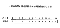
例えば、図11は、一実施形態に係るプロジェクタ100の装置名の初期値の一例を示した図である。図11では、11〜13バイト目に図8に示したプロジェクタ100に固有の製造番号の下3桁「0E0」が付加されている。このようにして、プロジェクタ100の装置名の初期値には、プロジェクタ100の装置名の製造番号を含める。これにより、プロジェクタ100の装置名の初期値はプロジェクタ100毎に異なる値に予め設定される、もしくは複数のプロジェクタ100で同値になる可能性が極端に低くなる。また、生成された値に更にアルファベットの文字を含めれば初期値が同値になる可能性は更に減る。更に、MACアドレスやプロジェクタ100の製造番号との組み合わせを使用すれば、初期値が同値になる可能性はなくなる。
For example, FIG. 11 is a diagram illustrating an example of an initial value of the device name of the
これにより、同種のプロジェクタ100等、接続される無線端末装置が複数あった場合であっても、無線端末装置の装置名をユーザが指定せずとも、接続するPC200により無線通信の接続時に間違いなく対象となる無線端末装置と他の無線端末装置とを区別することができる。
Accordingly, even when there are a plurality of wireless terminal devices to be connected, such as the
このように、異なるプロジェクタ100に同一のSSIDが付与されることはないということを利用して、PC200は、所望のプロジェクタ100と接続することを可能とし、そのプロジェクタ100に映像を投影することができる。
In this way, using the fact that the same SSID is not assigned to
また、本実施形態では、SSIDに装置名やMACアドレス等のプロジェクタ100を特定する情報が含まれるため、セキュリティ上、これらの値を隠したいときには、プロジェクタ100で変換を行い、PC200がSSIDを元に戻す。変換方法はどんな方法でもよいが、無線接続を行う機器間で予め決まっている。
In the present embodiment, since the SSID includes information for identifying the
[無線通信システムのシーケンス]
次に、本実施形態に係る無線通信システム1のシーケンスについて、図12を参照しながら説明する。図12は、一実施形態に係る無線通信システムのシーケンス図である。
[Sequence of wireless communication system]
Next, a sequence of the
例えば、ユーザが会議室に入り、会議室にあるプロジェクタ100と持ち込んだユーザのPC200との接続を確立する場合を想定する。
For example, it is assumed that a user enters a conference room and establishes a connection between the
まず、ユーザは、PC200の電源をオンし(1.0)、次いで、プロジェクタ100の電源をオンする(2.0)。 First, the user turns on the PC 200 (1.0), and then turns on the projector 100 (2.0).
プロジェクタ100は、無線設定情報を予め決められた第1の無線設定に変更し(2.1)、端末識別子を生成する(2.2)。次に、端末識別子を含むSSIDを生成する(2.3)。更に、SSIDを含むビーコンを生成し(2.4)、生成されたビーコンをPC200及び他の機器に対して随時、ブロードキャストする(2.5)。
The
PC200は、ビーコンを受信する(2.6)。ユーザは、PC200からプロジェクタ100への無線通信の接続を要求する(3.0)。PC200は、ビーコンからSSIDを取得する(3.1)。次に、PC200は、SSIDから端末識別子を抽出する(3.2)。次に、PC200は、端末識別子が含まれているSSIDに変更する(3.3)。次に、PC200は、予め定められた無線設定情報に変更する(3.4)。これにより、PC200は、プロジェクタ100との無線通信の接続を確立する。
The
無線通信の接続が確立された後は、ユーザがPC200からプロジェクタ100に映像の送信を要求し(4.0)、これに応じてPC200から所望の映像がプロジェクタ100に送信され(4.1)、プロジェクタ100に所望の映像が投影される。
(プロジェクタの選択表示)
図14(a)に示したように、無線の電波が届く範囲に3台のプロジェクタ(プロジェクタA100a、プロジェクタB100b、プロジェクタC100c)があった場合、プロジェクタA100a、プロジェクタB100b、プロジェクタC100cの情報として、それぞれの装置名、SSID、無線LAN、MACアドレスが、PC200上の画面に表示される。
After the wireless communication connection is established, the user requests the
(Projector selection display)
As shown in FIG. 14A, when there are three projectors (projector A100a, projector B100b, and projector C100c) within a range where radio waves reach, as information on projector A100a, projector B100b, and projector C100c, The device name, SSID, wireless LAN, and MAC address are displayed on the screen on the
その場合、PC200は、プロジェクタAからプロジェクタAに固有の識別情報を含むSSIDを取得し、図14(b)の左側の「プロジェクタAの表示内容」のようにPCの画面に表示する。同様にして、PC200は、プロジェクタBからプロジェクタBの固有の識別情報を含むSSIDを取得し、プロジェクタCからプロジェクタCの固有の識別情報を含むSSIDを取得してPCの画面に表示する。このようにして、「接続する無線端末装置」の一例であるPC200は、無線の電波が届く範囲に存在するすべての「接続される無線端末装置」からSSIDを取得し、PCの画面に「接続される無線端末装置」毎に表示する。
In that case, the
このようにして、PC200は、取得したSSIDから固有の識別情報を抽出し、プロジェクタAの情報、プロジェクタBの情報、プロジェクタCの情報としてそれら固有の識別情報を一覧にする。表示一覧を、図14(b)の右側に示す。プロジェクタAの情報、プロジェクタBの情報、プロジェクタCの情報が選択可能なように表示されている。プロジェクタAの詳細情報も選択情報の一つである。プロジェクタAの詳細情報はポップアップ形式にしてもよい。
In this way, the
ユーザは、PC200の表示画面に表示された固有の識別情報から、プロジェクタA100a、プロジェクタB100b、プロジェクタC100cを特定することができる。よって、ユーザは、無線通信の接続を要求するときに、接続したいプロジェクタを選択することができる。このユーザ操作に応じて、接続する側のPC200は、PC画面上にリスト表示されている複数のSSIDから所望のSSIDを選択し、SSID内の端末識別子に対応するプロジェクタに対して無線通信を要求する。
The user can specify the
ユーザは、例えばPCなどの接続する無線端末装置と、例えばプロジェクタ等の接続される無線端末装置とを自動で素早く接続し、PC内に記憶した映像をプロジェクタにより早く投影したいという要求が高い。よって、本実施形態のように、ユーザの選択操作をトリガとして自動的に無線通信の接続を開始することにより、接続までの時間を顕著に短縮することができる状態はユーザにとって大変好ましい。 There is a high demand for a user to quickly and automatically connect a wireless terminal device to be connected, such as a PC, and a wireless terminal device to be connected, such as a projector, and to quickly project an image stored in the PC. Therefore, as in the present embodiment, it is very preferable for the user that the time until the connection can be significantly shortened by automatically starting the wireless communication connection triggered by the user's selection operation.
表示された固有の識別情報の内容は、図14(b)の表示内容に限らず、例えば、プロジェクタの製造番号を表示してもよい。また、SSIDをすべて表示せず、SSIDに設定された情報の全部又は一部を表示するようにしてもよい。また、SSIDに含まれる固有の端末識別子(固有の識別情報)の全部又は一部を表示することもできる。 The content of the displayed unique identification information is not limited to the display content of FIG. 14B, and for example, a projector serial number may be displayed. Alternatively, all or part of the information set in the SSID may be displayed without displaying all SSIDs. It is also possible to display all or part of the unique terminal identifier (unique identification information) included in the SSID.
図14(b)に示したように、PC200の表示画面には、プロジェクタ毎の装置名、SSID、MACアドレス等がユーザの選択のために表示されている。しかし、例えばSSIDが数字とローマ字の羅列であると、どのプロジェクタを示しているのか判別しにくい。よって、SSIDの全部又は一部を表示する際、人間が視覚的に把握しやすい数字等に置き換えたり、色や書体を変えたり、強調表示を取り入れたりしてもよい。
As shown in FIG. 14B, the device name, SSID, MAC address, and the like for each projector are displayed on the display screen of the
具体例を挙げれば、第1の無線設定情報及び第2の無線設定情報には、会議室の識別情報が、第1会議室の番号「001」、第2会議室の番号「002」・・・というように、共通情報として予め設定されている。第1会議室001で使われるプロジェクタの情報を表示するとき、SSIDの一部の表示を「001(第1会議室の番号)」等に置き換え、かつその数字を太字にする。これにより、ユーザは適切なプロジェクタを選択することができる。
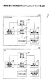
(無線通信の接続切断)
次に、無線通信の接続の切断について、図15を参照しながら説明する。図15は、一実施形態に係る接続終了時の無線通信システムのシーケンス図である。
For example, in the first wireless setting information and the second wireless setting information, the conference room identification information includes the first conference room number “001”, the second conference room number “002”,. As such, it is preset as common information. When displaying information on the projector used in the first conference room 001, the display of a part of the SSID is replaced with “001 (first conference room number)” and the number is bolded. Thereby, the user can select an appropriate projector.
(Wireless communication disconnection)
Next, disconnection of wireless communication will be described with reference to FIG. FIG. 15 is a sequence diagram of a wireless communication system at the end of connection according to an embodiment.
ユーザが通信の終了を要求すると(5.0)、PC200からプロジェクタ100に通信の終了が通知される(5.1)。また、第2のネットワーク制御部54は、無線設定情報の設定を予め決められた第2の無線設定情報から、変更前の無線設定情報に再設定する(5.2)。
When the user requests the end of communication (5.0), the
このようにして無線設定情報を予め決められた第2の無線接続の設定から変更前の無線設定情報に戻すことにより、接続する無線端末装置を元々接続されていたネットワークに復帰させることができる。
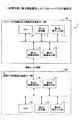
(重複したIPアドレスが存在した場合の処理)
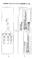
本実施形態に係る無線通信システム1では、同種の無線端末装置同士ではSSIDが必ず異なるため、IPアドレスが重複することが原因で通信ができない事態は発生しない。本実施形態に係る無線通信システム1では、別の無線端末装置においても、通常に使用する場合でIPアドレスが重複する可能性は非常に低い。しかしながら、万が一、IPアドレスが重複した場合の対策も予防策として取り得ることは好ましい。よって。以下ではIPアドレスが重複した場合の処理について図13を参照しながら説明する。図13は、一実施形態に係る重複したIPアドレスが存在した場合の処理フローを示した図である。
Thus, by returning the wireless setting information from the predetermined second wireless connection setting to the wireless setting information before the change, it is possible to return the connected wireless terminal device to the originally connected network.
(Processing when duplicate IP addresses exist)
In the
本処理が開始すると(S1)、プロジェクタ100は、無線設定情報を予め決められた第1の無線設定情報に変更し(S2)、端末識別子を生成し(S3)、端末識別子を含むSSIDを生成する(S4)。次に、プロジェクタ100は、無線の通信プロトコルがIPv4又はIPv6の場合、IPv4アドレス又はIPv6アドレスが、他の無線端末装置から送信されたビーコンのSSID中に存在するかを検出する(S5)。検出方法の一例としては、例えば、検出対象のIPv4アドレス又はIPv6アドレスを使って他の機器と通信を試みる方法がある。この場合、他の機器から返事があれば、そのIPアドレスは他の機器に使用されているためすでにIPアドレスは存在すると判定する。他の機器から返事がなければ、そのIPアドレスは存在しない(重複していない)と判定する。
When this process starts (S1), the
以上の検出結果に基づき、IPアドレスは存在しないと判定された場合には、プロジェクタ100は、通常通り、生成したSSIDを含むビーコンを生成し、送信する(S6)。一方、IPアドレスは存在すると判定された場合には、プロジェクタ100は、接続ができないことを通知し、ユーザに警告する(S7)。
If it is determined that the IP address does not exist based on the above detection result, the
これにより、IPアドレスが重複することが原因で通信ができない事態が発生することを防止することができる。
(複数台のプロジェクタが存在する場合の切り替え)
次に、PC200から送信される映像の投影先を別のプロジェクタに切り替える場合の処理について、図16を参照しながら説明する。
As a result, it is possible to prevent a situation in which communication cannot be performed due to overlapping IP addresses.
(Switching when there are multiple projectors)
Next, processing when the projection destination of the video transmitted from the
電源ON(1.0、2.0)の後に行われる、2.1〜2.6の処理(プロジェクタA側)、電源ON(2.7)の後に行われる、2.8〜2.13の処理(プロジェクタB側)は、図12にて説明した電源ON(1.0、2.0)の後の2.1〜2.6の処理と同様であるため、ここでは説明を省略する。つまり、プロジェクタ毎にビーコンの生成及び送信が実行され、PC200は、プロジェクタA,Bのビーコンを受信する。
Processes 2.1 to 2.6 (projector A side) performed after power ON (1.0, 2.0), 2.8 to 2.13 performed after power ON (2.7) The process (projector B side) is the same as the process 2.1 to 2.6 after the power-on (1.0, 2.0) described with reference to FIG. . That is, generation and transmission of a beacon are executed for each projector, and the
ユーザがPC200からプロジェクタへの接続を要求すると(3.0)、PC200は、受信ビーコンからSSIDを取得する(3.1)。ここでは、最初に受信したビーコンからSSIDを取得する。
When the user requests connection from the
次に、PC200は、SSIDから端末識別子を抽出する(3.2)。ここでは、プロジェクタAの端末を示す端末識別子1を含むSSIDが先に取得されたものとする。よって、この時点では、PC200は、端末識別子1を含むSSIDに変更する(3.3)。次に、PC200は、予め定められた無線設定情報に変更する(3.4)。これにより、PC200は、プロジェクタAとの無線通信の接続を確立する。
Next, the
PC200は、接続される無線端末装置のリストを表示する(3.5)。これに対して、ユーザは、リストからプロジェクタBを選択し、プロジェクタBへの接続を要求する(4.0)。これに応じて、PC200は、選択されたプロジェクタBの端末を示す端末識別子2を含むSSIDに変更する(4.1)。次に、PC200は、予め定められた無線設定情報に変更する(4.2)。これにより、PC200は、プロジェクタBとの無線通信の接続を確立する。
The
ユーザはPC200からプロジェクタBへの通信を指示し(5.0)、PC200は、プロジェクタBへデータを送信する(5.1)。この結果、PC200の映像は、プロジェクタBに投影される。
(複数台のPCが存在する場合の切り替え)
次に、プロジェクタに映像を送るPCが複数存在する場合の切り替え処理について、図17を参照しながら説明する。
The user instructs communication from the
(Switching when there are multiple PCs)
Next, switching processing when there are a plurality of PCs that send images to the projector will be described with reference to FIG.
この場合、図12で示したビーコンをプロジェクタ100からPC−A200a及びPC−B200bに送受信後(2.5〜2.8)のPC側の一連のシーケンスの流れ(3.0〜4.1、5.0〜6.1)を複数台のPCが別々に処理する。
In this case, a series of sequence flows (3.0 to 4.1, 3.0 to 4.1) after transmitting and receiving the beacon illustrated in FIG. 12 from the
つまり、図17で示したビーコンの送信後(2.5、2.7)、2台のPC−A200a及びPC−B200bがビーコンを受信する(2.6、2.8)。
That is, after transmitting the beacon shown in FIG. 17 (2.5, 2.7), two PC-A 200a and PC-
ユーザがPC−A200aからプロジェクタ100への接続を指示した場合(3.0)、PC−A200aは、ビーコンからSSIDを取得し(3.1)、SSIDから端末識別子を抽出し(3.2)、端末識別子を含むSSIDに変更し(3.3)、予め定められた無線設定情報に変更する(3.4)。これにより、PC−A200aは、プロジェクタとの無線通信の接続を確立する。 When the user instructs the connection from the PC-A 200a to the projector 100 (3.0), the PC-A 200a acquires the SSID from the beacon (3.1), and extracts the terminal identifier from the SSID (3.2). Then, the SSID including the terminal identifier is changed (3.3), and the wireless setting information is changed to predetermined wireless setting information (3.4). Thereby, the PC-A 200a establishes a wireless communication connection with the projector.
その後、ユーザからの通信要求がなされると(4.0)、PC−A200aは、これに応じて所望のデータをプロジェクタ100に送信し、プロジェクタ100に投影させる(4.1)。
Thereafter, when a communication request is made from the user (4.0), the PC-A 200a transmits desired data to the
ユーザがPC−B200bからプロジェクタ100への接続を指示した場合も、上述した処理と同様に5.0〜5.4、6.0〜6.1の処理を行う。これにより、PC−B200bは、プロジェクタ100との無線通信の接続を確立し、所望のデータをプロジェクタ100に投影させることができる。
(ユーザが接続を指示する場合)
通常、PCの近くに存在する接続対象のプロジェクタは1台しかない場合が多い。よって、図12の接続の確立では、接続可能なプロジェクタをPC画面にリスト表示し、ユーザに所望のプロジェクタを選択させることはせず、最初に見つかったSSIDに含まれる端末識別子を持つプロジェクタに自動的に接続する。
Even when the user instructs the connection from the PC-
(When the user instructs connection)
Usually, there is often only one projector to be connected that exists near the PC. Therefore, in the establishment of the connection in FIG. 12, a list of connectable projectors is displayed on the PC screen, and the user is not allowed to select a desired projector, and the projector having the terminal identifier included in the first SSID found is automatically selected. Connect.
これに対して、図18では、最初に見つかったSSIDに自動的に接続せず、ユーザに所望のプロジェクタを選択させて、そのプロジェクタとの接続を確立する。この場合について簡単に説明する。 On the other hand, in FIG. 18, the user does not automatically connect to the first SSID found, but allows the user to select a desired projector and establishes a connection with the projector. This case will be briefly described.
図18の1.0、2.0〜2.13の処理は、図16と同様であるためここでは説明を省略する。次に、図18では、ユーザはプロジェクタの一覧表示を要求する(3.0)。これに応じて、PC200は、プロジェクタA100aから受信したビーコンからSSIDを取得するとともに、プロジェクタB100bから受信したビーコンからSSIDを取得する(3.1)。そして、2つのSSIDから端末識別子(すなわち、端末識別子1、端末識別子2)を抽出し(3.2)、それらをPC画面にリスト表示する(3.3)。
The processes of 1.0 and 2.0 to 2.13 in FIG. 18 are the same as those in FIG. Next, in FIG. 18, the user requests display of a list of projectors (3.0). In response to this, the
これに対して、例えば、ユーザがPC画面のリスト表示からプロジェクタBの端末識別子を選択し、プロジェクタB100bに接続するように要求すると(4.0)、PC200は、指定された端末識別子2を含むSSIDに変更し(4.1)、予め決められた無線設定情報に変更する(4.2)。これによりPC200は、プロジェクタB100bとの無線通信の接続を確立する。その後、ユーザから通信要求が出されると(5.0)、これに応じてPC200は、所望のデータをプロジェクタBに送信する(5.1)。
On the other hand, for example, when the user selects the terminal identifier of the projector B from the list display on the PC screen and requests to connect to the
[効果]
以上説明したように、本実施形態に係る無線通信システム1によれば、ビーコンに様々な情報を含ませて送信する。接続する無線端末装置はビーコンを受信する。このとき、ビーコンは定期的に出続けているから、PCからの接続時にプロジェクタのSSIDを含む接続情報を時間のかかるアクティブスキャンによって取得する必要がない。これにより無線通信の高速接続が可能になる。また、無線通信における共通情報は、接続される無線端末装置と接続する無線端末装置とで予め設定された第1の無線設定情報と第2の無線設定情報としてそれぞれの保存領域に保持されている。このため、無線通信接続時、接続する無線端末装置と接続される無線端末装置との間で、無線通信の接続に必要な情報を交換する回数を少なくすることができる。これにより無線通信の接続時間を短縮することができる。更に、無線通信において通信パケットが通信相手の無線端末装置まで届かずに接続の確立に失敗する確率を低く抑えることができる。
[effect]
As described above, according to the
以上、添付図面を参照しながら本発明の好適な実施形態について詳細に説明したが、本発明はかかる例に限定されない。本発明の属する技術の分野における通常の知識を有する者であれば、特許請求の範囲に記載された技術的思想の範疇において、各種の変更例または修正例に想到し得ることは明らかであり、これらについても、当然に本発明の技術的範囲に属するものと了解される。 The preferred embodiments of the present invention have been described in detail above with reference to the accompanying drawings, but the present invention is not limited to such examples. It is obvious that a person having ordinary knowledge in the technical field to which the present invention belongs can come up with various changes or modifications within the scope of the technical idea described in the claims. Of course, it is understood that these also belong to the technical scope of the present invention.
1 無線通信システム
16 第1の無線通信部
18 第1の映像出力部
26 第2の無線通信部
28 第2の映像出力部
32 第1の無線設定保持部
34 第1のネットワーク制御部
36 端末識別子生成部
38 SSID生成部
40 第1の映像表示部
50 第2のユーザ操作部
52 第2の無線設定保持部
54 第2のネットワーク制御部
56 端末識別子抽出部
58 SSID抽出部
60 第2の映像表示部
100 プロジェクタ
200 PC
DESCRIPTION OF
Claims (23)
前記接続される無線端末装置は、
前記接続する無線端末装置に保持される第2の無線設定情報との無線通信における共通情報として予め定められた第1の無線設定情報を設定する第1のネットワーク制御部と、
前記無線通信における固有の識別情報を含むSSIDを生成する生成部と、
前記生成されたSSIDを含むビーコンを送信する第1の無線通信部と、を備え、
前記接続する無線端末装置は、
前記ビーコンを受信する第2の無線通信部と、
前記ビーコンから前記SSIDを抽出し、該抽出されたSSIDに含まれる前記固有の識別情報を抽出する抽出部と、
前記第2の無線設定情報を保持する第2の保持部と、
前記第2の無線設定情報を設定し、前記抽出された固有の識別情報と前記第2の無線設定情報とを用いて前記接続される無線端末装置との無線通信の接続を確立する第2のネットワーク制御部と、
を備えることを特徴とする無線通信システム。 A wireless communication system capable of wireless communication with a connected wireless terminal device and a wireless terminal device connected thereto,
The connected wireless terminal device is:
A first network control unit configured to set first wireless setting information predetermined as common information in wireless communication with second wireless setting information held in the connected wireless terminal device;
A generating unit that generates an SSID including unique identification information in the wireless communication;
A first wireless communication unit that transmits a beacon including the generated SSID,
The wireless terminal device to be connected is
A second wireless communication unit that receives the beacon;
An extraction unit that extracts the SSID from the beacon and extracts the unique identification information included in the extracted SSID;
A second holding unit for holding the second wireless setting information;
The second wireless setting information is set, and a wireless communication connection with the connected wireless terminal device is established using the extracted unique identification information and the second wireless setting information. A network controller;
A wireless communication system comprising:
前記第2の無線設定情報と異なる値に設定されている場合、前記第2の無線設定情報に設定を変更することを特徴とする請求項1に記載の無線通信システム。 The second network controller is
The wireless communication system according to claim 1, wherein when the second wireless setting information is set to a value different from the second wireless setting information, the setting is changed to the second wireless setting information.
前記第1の無線設定情報と異なる値に設定されている場合、前記第1の無線設定情報に設定を変更することを特徴とする請求項1又は2に記載の無線通信システム。 The first network control unit
3. The wireless communication system according to claim 1, wherein when a value different from the first wireless setting information is set, the setting is changed to the first wireless setting information. 4.
前記第1の保持部は、
無線の通信モード、認証方式、暗号方式、無線の通信プロトコル及び無線のIP(Internet Protocol)アドレスを含んだ前記第1の無線設定情報を保持し、
前記第2の保持部は、
前記第1の無線設定情報に対応する無線の通信モード、認証方式、暗号方式、無線の通信プロトコル及び無線のIPアドレスを含んだ前記第2の無線設定情報を保持することを特徴とする請求項1〜3のいずれか一項に記載の無線通信システム。 A first holding unit that holds the first wireless setting information set in advance as common information in wireless communication with the second wireless setting information;
The first holding part is
Holding the first wireless setting information including a wireless communication mode, an authentication method, an encryption method, a wireless communication protocol, and a wireless IP (Internet Protocol) address;
The second holding part is
The wireless communication mode, authentication method, encryption method, wireless communication protocol, and wireless IP address corresponding to the first wireless setting information are stored in the second wireless setting information. The radio | wireless communications system as described in any one of 1-3.
前記無線の通信モードとして、アクセスポイントを介さずに無線通信を行うアドホックモードまたはアクセスポイントを介して無線通信を行うインフラストラクチャモードのいずれかを設定することを特徴とする請求項4に記載の無線通信システム。 The first holding unit and the second holding unit are:
The wireless communication mode according to claim 4, wherein the wireless communication mode is set to either an ad hoc mode in which wireless communication is performed without using an access point or an infrastructure mode in which wireless communication is performed through an access point. Communications system.
前記無線のIPアドレスとして、無線のIPv4(Internet Protocol version4)アドレスと無線のIPv4サブネットマスクアドレスを設定することを特徴とする請求項4又は5に記載の無線通信システム。 The first holding unit and the second holding unit are:
6. The wireless communication system according to claim 4, wherein a wireless IPv4 (Internet Protocol version 4) address and a wireless IPv4 subnet mask address are set as the wireless IP address.
前記無線のIPアドレスとして、無線のIPv6(Internet Protocol version6)アドレスと無線のIPv6アドレスプレフィックスとを設定することを特徴とする請求項4又は5に記載の無線通信システム。 The first holding unit and the second holding unit are:
6. The wireless communication system according to claim 4, wherein a wireless IPv6 (Internet Protocol version 6) address and a wireless IPv6 address prefix are set as the wireless IP address.
更に、周波数チャンネル及び伝送規格の少なくともいずれかを含んだ前記第1の無線設定情報及び前記第2の無線設定情報を保持することを特徴とする請求項4〜7のいずれか一項に記載の無線通信システム。 The first holding unit and the second holding unit are:
Further, the first wireless setting information and the second wireless setting information including at least one of a frequency channel and a transmission standard are held. 8. Wireless communication system.
周波数チャンネルに予め定められた値を設定する、又は走査して得られたユーザ指定の周波数チャンネルの値を設定することを特徴とする請求項8に記載の無線通信システム。 The first holding unit and the second holding unit are:
9. The wireless communication system according to claim 8, wherein a predetermined value is set for the frequency channel, or a value of a user-specified frequency channel obtained by scanning is set.
前記接続される無線端末装置に関する固有の識別情報であることを特徴とする請求項1〜9のいずれか一項に記載の無線通信システム。 The unique identification information in the wireless communication is
The wireless communication system according to claim 1, wherein the wireless communication system is unique identification information related to the connected wireless terminal device.
前記無線通信におけるMACアドレス、前記MACアドレスの値を変換した識別情報、前記接続される無線端末装置の製造番号、前記接続される無線端末装置の製造番号の値を変換した値、乱数の少なくともいずれかであることを特徴とする請求項10に記載の無線通信システム。 The unique identification information regarding the connected wireless terminal device is:
At least one of a MAC address in the wireless communication, identification information obtained by converting the value of the MAC address, a manufacturing number of the connected wireless terminal device, a value converted of a manufacturing number of the connected wireless terminal device, and a random number The wireless communication system according to claim 10, wherein
ユーザ操作により取得した情報、無線設定情報を識別するための情報、前記接続される無線端末装置の装置名の少なくともいずれかの値を含んだ前記SSIDを生成することを特徴とする請求項1〜11のいずれか一項に記載の無線通信システム。 The generator is
The SSID including at least one of values obtained by user operation, information for identifying wireless setting information, and a device name of the connected wireless terminal device is generated. 11. The wireless communication system according to claim 11.
前記接続される無線端末装置の装置名の初期値が含まれ、該初期値は前記接続される無線端末装置毎に異なる値に予め設定されていることを特徴とする請求項12に記載の無線通信システム。 The device name of the connected wireless terminal device includes:
13. The wireless device according to claim 12, wherein an initial value of a device name of the connected wireless terminal device is included, and the initial value is preset to a different value for each connected wireless terminal device. Communications system.
前記生成後のSSIDの文字列を暗号化し、
前記第2の無線通信部は、
前記ビーコンに含まれるSSIDを復号することを特徴とする請求項1〜13のいずれか一項に記載の無線通信システム。 The first wireless communication unit is
Encrypt the generated SSID character string,
The second wireless communication unit is
The wireless communication system according to claim 1, wherein the SSID included in the beacon is decoded.
前記無線の通信プロトコルがIPv4又はIPv6の場合、すでに同一のIPv4アドレス又はIPv6アドレスが、他の無線端末装置から送信されたビーコンのSSID中に存在するかを検出し、検出の結果、存在すると判定した場合、前記無線通信の接続を確立できないことを通知することを特徴とする請求項6又は7に記載の無線通信システム。 The connected wireless terminal device is:
When the wireless communication protocol is IPv4 or IPv6, it is detected whether the same IPv4 address or IPv6 address already exists in the SSID of the beacon transmitted from another wireless terminal device, and it is determined that it exists as a result of the detection. When it does, it notifies that the connection of the said wireless communication cannot be established, The wireless communication system of Claim 6 or 7 characterized by the above-mentioned.
前記接続される無線端末装置は、
複数の前記接続される無線端末装置から一の接続される無線端末装置を選択するための選択情報を表示する第1の表示部を有することを特徴とする請求項1〜15のいずれか一項に記載の無線通信システム。 When there are a plurality of wireless terminal device candidates to be connected to the connected wireless terminal device,
The connected wireless terminal device is:
16. The apparatus according to claim 1, further comprising a first display unit that displays selection information for selecting one connected wireless terminal device from the plurality of connected wireless terminal devices. The wireless communication system according to 1.
前記接続される無線端末装置の選択情報として、前記生成されたSSIDに設定された情報の全部又は一部を表示することを特徴とする請求項16に記載の無線通信システム。 The first display unit includes:
The wireless communication system according to claim 16, wherein all or part of information set in the generated SSID is displayed as selection information of the connected wireless terminal device.
前記SSIDに含まれる前記固有の識別情報の全部又は一部を表示する第2の表示部を有することを特徴とする請求項1〜17のいずれか一項に記載の無線通信システム。 The wireless terminal device to be connected is
The wireless communication system according to any one of claims 1 to 17, further comprising a second display unit that displays all or part of the unique identification information included in the SSID.
リスト形式に複数の前記固有の識別情報を表示することを特徴とする請求項18に記載の無線通信システム。 The second display unit includes:
The wireless communication system according to claim 18, wherein a plurality of the unique identification information is displayed in a list format.
前記切り替え後新たに接続する無線端末装置の前記第2の無線通信部は、前記固有の識別情報により識別される接続される無線端末装置から送信されたビーコンを受信し、
前記抽出部は、前記ビーコンから前記SSIDを抽出し、該SSIDに変更し、
無線設定情報を、前記新たに接続する無線端末装置の第2の無線設定情報に変更することを特徴とすることを特徴とする請求項1〜19のいずれか一項に記載の無線通信システム。 After establishing the wireless communication connection, when the wireless terminal device to be connected is switched,
The second wireless communication unit of the wireless terminal device newly connected after the switching receives a beacon transmitted from the connected wireless terminal device identified by the unique identification information,
The extraction unit extracts the SSID from the beacon, changes the SSID,
The wireless communication system according to any one of claims 1 to 19, wherein wireless setting information is changed to second wireless setting information of the newly connected wireless terminal device.
前記第2のネットワーク制御部は、無線設定情報の設定を変更前の無線設定情報に再設定することを特徴とすることを特徴とする請求項1〜20のいずれか一項に記載の無線通信システム。 When disconnecting the established wireless communication connection,
The wireless communication according to any one of claims 1 to 20, wherein the second network control unit resets the setting of the wireless setting information to the wireless setting information before the change. system.
前記接続する無線端末装置に保持される第2の無線設定情報との共通情報として予め定められた第1の無線設定情報を設定する第1のネットワーク制御ステップと、
前記無線通信における固有の識別情報を含むSSIDを生成する生成ステップと、
前記生成されたSSIDを含むビーコンを送信する第1の無線通信ステップと、
前記ビーコンを受信する第2の無線通信ステップと、
前記ビーコンから前記SSIDを抽出し、該抽出されたSSIDに含まれる前記固有の識別情報を抽出する抽出ステップと、
前記第1の無線設定情報との共通情報として予め設定された前記第2の無線設定情報を保持する第2の保持ステップと、
前記第2の無線設定情報を設定する設定ステップと、
前記抽出された固有の識別情報と前記第2の無線設定情報とを用いて前記接続される無線端末装置との無線通信の接続を確立する第2のネットワーク制御ステップと、
を含むことを特徴とする無線通信方法。 A wireless communication method for wirelessly communicating between a connected wireless terminal device and a connected wireless terminal device,
A first network control step for setting first wireless setting information predetermined as common information with second wireless setting information held in the connected wireless terminal device;
Generating a SSID including unique identification information in the wireless communication;
A first wireless communication step of transmitting a beacon including the generated SSID;
A second wireless communication step of receiving the beacon;
An extraction step of extracting the SSID from the beacon and extracting the unique identification information included in the extracted SSID;
A second holding step for holding the second wireless setting information set in advance as common information with the first wireless setting information;
A setting step for setting the second wireless setting information;
A second network control step for establishing a wireless communication connection with the connected wireless terminal device using the extracted unique identification information and the second wireless setting information;
A wireless communication method comprising:
前記他の無線端末装置に保持される第2の無線設定情報との共通情報として予め定められた第1の無線設定情報を設定する第1のネットワーク制御部と、
前記無線通信における固有の識別情報を含むSSIDを生成する生成部と、
前記生成されたSSIDを含むビーコンを送信する第1の無線通信部と、を備え、
前記他の無線端末装置に、前記ビーコン中の前記SSIDに含まれる固有の識別情報と前記第2の無線設定情報とを用いて自機との無線通信の接続を確立させることを特徴とする無線端末装置。 A wireless terminal device capable of wireless communication with other wireless terminal devices,
A first network control unit configured to set first wireless setting information predetermined as common information with second wireless setting information held in the other wireless terminal device;
A generating unit that generates an SSID including unique identification information in the wireless communication;
A first wireless communication unit that transmits a beacon including the generated SSID,
A wireless communication device that causes the other wireless terminal device to establish a wireless communication connection with its own device using unique identification information included in the SSID in the beacon and the second wireless setting information. Terminal device.
Priority Applications (4)
| Application Number | Priority Date | Filing Date | Title |
|---|---|---|---|
| JP2012091383A JP2013222991A (en) | 2012-04-12 | 2012-04-12 | Radio communication system, radio communication method, and radio terminal device |
| US13/858,992 US9301326B2 (en) | 2012-04-12 | 2013-04-09 | Wireless communication system, wireless communication method, and wireless terminal |
| EP13163441.2A EP2651162A3 (en) | 2012-04-12 | 2013-04-12 | Wireless communication system, wireless communication method, and wireless terminal |
| CN201310126070.7A CN103379589B (en) | 2012-04-12 | 2013-04-12 | Wireless communication system, wireless communications method and wireless terminal |
Applications Claiming Priority (1)
| Application Number | Priority Date | Filing Date | Title |
|---|---|---|---|
| JP2012091383A JP2013222991A (en) | 2012-04-12 | 2012-04-12 | Radio communication system, radio communication method, and radio terminal device |
Related Child Applications (1)
| Application Number | Title | Priority Date | Filing Date |
|---|---|---|---|
| JP2015022101A Division JP6056885B2 (en) | 2015-02-06 | 2015-02-06 | Wireless communication system, wireless communication method, and first communication apparatus |
Publications (2)
| Publication Number | Publication Date |
|---|---|
| JP2013222991A true JP2013222991A (en) | 2013-10-28 |
| JP2013222991A5 JP2013222991A5 (en) | 2014-07-17 |
Family
ID=48087447
Family Applications (1)
| Application Number | Title | Priority Date | Filing Date |
|---|---|---|---|
| JP2012091383A Pending JP2013222991A (en) | 2012-04-12 | 2012-04-12 | Radio communication system, radio communication method, and radio terminal device |
Country Status (4)
| Country | Link |
|---|---|
| US (1) | US9301326B2 (en) |
| EP (1) | EP2651162A3 (en) |
| JP (1) | JP2013222991A (en) |
| CN (1) | CN103379589B (en) |
Cited By (10)
| Publication number | Priority date | Publication date | Assignee | Title |
|---|---|---|---|---|
| JP2015179885A (en) * | 2014-03-18 | 2015-10-08 | Necプラットフォームズ株式会社 | Radio device, receiver, and radio communication method |
| KR101567333B1 (en) * | 2014-04-25 | 2015-11-10 | 주식회사 크레스프리 | Mobile communication terminal and module for establishing network communication of IoT device and method of establishing network communication of IoT device with using mobile communication terminal |
| JP2016201701A (en) * | 2015-04-10 | 2016-12-01 | キヤノン株式会社 | Communication device, control method thereof, and program |
| JP2017046227A (en) * | 2015-08-27 | 2017-03-02 | 株式会社バッファロー | Radio communication system, terminal device, access point, and program |
| JP2017525287A (en) * | 2014-07-31 | 2017-08-31 | ホアウェイ・テクノロジーズ・カンパニー・リミテッド | Method, apparatus and system for establishing a connection by a terminal |
| WO2017212602A1 (en) * | 2016-06-09 | 2017-12-14 | Necディスプレイソリューションズ株式会社 | Projector having wireless lan terminal function, method for wireless lan connection of said projector, and projection system |
| JP2018011356A (en) * | 2017-10-05 | 2018-01-18 | 株式会社Jvcケンウッド | Communication device and communication method |
| JP2018194890A (en) * | 2017-05-12 | 2018-12-06 | 株式会社リコー | Information processing apparatus, electronic device, setting information utilization method and program |
| WO2018220817A1 (en) * | 2017-06-02 | 2018-12-06 | Necディスプレイソリューションズ株式会社 | Electronic device, wireless lan terminal and wireless lan system |
| US10356792B2 (en) | 2014-11-21 | 2019-07-16 | JVC Kenwood Corporation | Communication terminal device, communication system, communication method compatible with at least two communication schemes |
Families Citing this family (19)
| Publication number | Priority date | Publication date | Assignee | Title |
|---|---|---|---|---|
| JP2014158255A (en) | 2013-01-16 | 2014-08-28 | Ricoh Co Ltd | Radio communication apparatus, radio communication method, and program |
| CN103686293A (en) * | 2013-12-30 | 2014-03-26 | 天津三星电子有限公司 | Television control terminal and data transmission connection establishing method |
| KR102139998B1 (en) * | 2014-03-21 | 2020-08-03 | 에스케이플래닛 주식회사 | Security control system and method for beacon and control apparatus thereof |
| CN103987017B (en) * | 2014-06-03 | 2017-09-19 | 北京奇虎科技有限公司 | A kind of method and system for being used to set up service access in a wlan |
| CN105323516B (en) * | 2014-06-17 | 2019-07-12 | 中强光电股份有限公司 | Optical projection system and method for controlling projection |
| TWI530223B (en) * | 2014-07-22 | 2016-04-11 | 廣達電腦股份有限公司 | Method, system and device of establishing link |
| US9621417B2 (en) * | 2014-09-30 | 2017-04-11 | Ruckus Wireless, Inc. | Avoiding electronic-device identification errors |
| JP2016177097A (en) | 2015-03-19 | 2016-10-06 | キヤノン株式会社 | Communication device, communication device control method, and display system |
| JP2016177088A (en) * | 2015-03-19 | 2016-10-06 | 株式会社リコー | Display control device, display control system, graphical user interface, and display control program |
| JP6525714B2 (en) * | 2015-04-30 | 2019-06-05 | キヤノン株式会社 | Communication device, control method of communication device, and program |
| JP6585957B2 (en) * | 2015-07-31 | 2019-10-02 | キヤノン株式会社 | Radiographic system, control method of radiographic system, and control apparatus |
| CN105227650B (en) * | 2015-09-23 | 2019-10-11 | Tcl移动通信科技(宁波)有限公司 | File sharing method and system between a kind of mobile terminal |
| JP6744783B2 (en) | 2016-08-17 | 2020-08-19 | キヤノン株式会社 | Information processing apparatus, control method thereof, and program |
| CN106535294A (en) * | 2016-10-20 | 2017-03-22 | 珠海市魅族科技有限公司 | Network connection method, device and system |
| DE102016223633A1 (en) | 2016-11-29 | 2018-05-30 | Siemens Aktiengesellschaft | Method and devices for providing at least one service, in particular in the automotive environment |
| US11032143B2 (en) | 2018-08-03 | 2021-06-08 | Netapp, Inc. | Assignment of network configuration for a wired network using a wireless network |
| CN109582263A (en) * | 2018-10-26 | 2019-04-05 | 深圳点猫科技有限公司 | The method and electronic equipment of projection device are wirelessly connected based on Linux |
| US11658781B2 (en) | 2019-05-03 | 2023-05-23 | Qualcomm Incorporated | Techniques for updating reference signals |
| CN113765903B (en) * | 2021-08-26 | 2023-07-28 | 科大讯飞股份有限公司 | Screen projection method, related device, electronic equipment and storage medium |
Citations (10)
| Publication number | Priority date | Publication date | Assignee | Title |
|---|---|---|---|---|
| JP2005167696A (en) * | 2003-12-03 | 2005-06-23 | Canon Inc | Wireless communication controller and its control method |
| JP2006086959A (en) * | 2004-09-17 | 2006-03-30 | Fujitsu Ltd | Radio terminal and ad hoc communication method |
| JP2006157815A (en) * | 2004-12-01 | 2006-06-15 | Kddi Corp | Cellular phone adaptable to wireless lan and wireless lan setting method thereof |
| JP2007135146A (en) * | 2005-11-14 | 2007-05-31 | Fujitsu Access Ltd | System and method for wireless lan communication |
| JP2007143117A (en) * | 2005-10-17 | 2007-06-07 | Canon Inc | Communication apparatus and communication parameter setting method |
| JP2009231971A (en) * | 2008-03-19 | 2009-10-08 | Seiko Epson Corp | Radio communication system, electronic equipment, ad-hoc network establishment method |
| JP2011166600A (en) * | 2010-02-12 | 2011-08-25 | Toshiba Corp | Portable radio terminal |
| JP2013009069A (en) * | 2011-06-23 | 2013-01-10 | Ntt Docomo Inc | Mobile communication system, mobile telephone terminal, data access point and method therefor, using usim proper information |
| JP2013066175A (en) * | 2011-09-02 | 2013-04-11 | Panasonic Corp | Wireless communication device, projector apparatus, wireless communication system, and wireless communication method |
| JP2013179454A (en) * | 2012-02-28 | 2013-09-09 | Brother Ind Ltd | Portable information processing device, karaoke system, and program |
Family Cites Families (21)
| Publication number | Priority date | Publication date | Assignee | Title |
|---|---|---|---|---|
| US7620713B2 (en) * | 2002-04-23 | 2009-11-17 | Sharp Kabushiki Kaisha | Device control management apparatus |
| US7769837B2 (en) * | 2003-12-12 | 2010-08-03 | Brother Kogyo Kabushiki Kaisha | Wireless LAN setting system and communication terminal |
| US7546357B2 (en) * | 2004-01-07 | 2009-06-09 | Microsoft Corporation | Configuring network settings using portable storage media |
| US20050198233A1 (en) * | 2004-01-07 | 2005-09-08 | Microsoft Corporation | Configuring network settings of thin client devices using portable storage media |
| JP2005198154A (en) * | 2004-01-09 | 2005-07-21 | Seiko Epson Corp | Method for setting radio communication equipment |
| JP2006254301A (en) | 2005-03-14 | 2006-09-21 | Fuji Xerox Co Ltd | Ip address setting system |
| US7616594B2 (en) * | 2005-04-22 | 2009-11-10 | Microsoft Corporation | Wireless device discovery and configuration |
| US7648812B2 (en) | 2005-08-01 | 2010-01-19 | Ricoh Company Limited | Toner, developer, and image forming apparatus |
| JP2007065620A (en) | 2005-08-01 | 2007-03-15 | Ricoh Co Ltd | Toner and image forming apparatus |
| JP2007096464A (en) | 2005-09-27 | 2007-04-12 | Toshiba Corp | Access point and communication method |
| US8576846B2 (en) * | 2005-10-05 | 2013-11-05 | Qualcomm Incorporated | Peer-to-peer communication in ad hoc wireless network |
| KR100765768B1 (en) * | 2005-12-07 | 2007-10-15 | 삼성전자주식회사 | Method and apparatus of auto configuration on wireless communication network, wireless communication network thereof |
| JP5239123B2 (en) | 2006-03-15 | 2013-07-17 | 日本電気株式会社 | Wireless LAN system |
| US9445353B2 (en) * | 2006-09-14 | 2016-09-13 | Omnitrail Technologies Inc. | Presence platform for passive radio access network-to-radio access network device transition |
| JP4944564B2 (en) * | 2006-10-20 | 2012-06-06 | キヤノン株式会社 | COMMUNICATION PARAMETER SETTING METHOD, COMMUNICATION DEVICE, COMMUNICATION DEVICE CONTROL METHOD, AND PROGRAM |
| JP2008219550A (en) | 2007-03-06 | 2008-09-18 | Sony Ericsson Mobilecommunications Japan Inc | Information providing system and mobile terminal |
| JP5053715B2 (en) * | 2007-05-31 | 2012-10-17 | キヤノン株式会社 | COMMUNICATION DEVICE, COMMUNICATION DEVICE CONTROL METHOD, AND COMPUTER PROGRAM FOR CAUSING COMPUTER TO EXECUTE THE CONTROL METHOD |
| JP4613969B2 (en) * | 2008-03-03 | 2011-01-19 | ソニー株式会社 | Communication apparatus and communication method |
| JP2010136308A (en) | 2008-12-08 | 2010-06-17 | Brother Ind Ltd | Control device for radio communication apparatus |
| JP5293649B2 (en) | 2010-03-09 | 2013-09-18 | セイコーエプソン株式会社 | Wireless communication system, wireless communication terminal, and wireless communication method |
| US9137171B2 (en) * | 2011-12-19 | 2015-09-15 | Cisco Technology, Inc. | System and method for resource management for operator services and internet |
-
2012
- 2012-04-12 JP JP2012091383A patent/JP2013222991A/en active Pending
-
2013
- 2013-04-09 US US13/858,992 patent/US9301326B2/en active Active
- 2013-04-12 CN CN201310126070.7A patent/CN103379589B/en active Active
- 2013-04-12 EP EP13163441.2A patent/EP2651162A3/en not_active Ceased
Patent Citations (10)
| Publication number | Priority date | Publication date | Assignee | Title |
|---|---|---|---|---|
| JP2005167696A (en) * | 2003-12-03 | 2005-06-23 | Canon Inc | Wireless communication controller and its control method |
| JP2006086959A (en) * | 2004-09-17 | 2006-03-30 | Fujitsu Ltd | Radio terminal and ad hoc communication method |
| JP2006157815A (en) * | 2004-12-01 | 2006-06-15 | Kddi Corp | Cellular phone adaptable to wireless lan and wireless lan setting method thereof |
| JP2007143117A (en) * | 2005-10-17 | 2007-06-07 | Canon Inc | Communication apparatus and communication parameter setting method |
| JP2007135146A (en) * | 2005-11-14 | 2007-05-31 | Fujitsu Access Ltd | System and method for wireless lan communication |
| JP2009231971A (en) * | 2008-03-19 | 2009-10-08 | Seiko Epson Corp | Radio communication system, electronic equipment, ad-hoc network establishment method |
| JP2011166600A (en) * | 2010-02-12 | 2011-08-25 | Toshiba Corp | Portable radio terminal |
| JP2013009069A (en) * | 2011-06-23 | 2013-01-10 | Ntt Docomo Inc | Mobile communication system, mobile telephone terminal, data access point and method therefor, using usim proper information |
| JP2013066175A (en) * | 2011-09-02 | 2013-04-11 | Panasonic Corp | Wireless communication device, projector apparatus, wireless communication system, and wireless communication method |
| JP2013179454A (en) * | 2012-02-28 | 2013-09-09 | Brother Ind Ltd | Portable information processing device, karaoke system, and program |
Non-Patent Citations (1)
| Title |
|---|
| 外村 克也, パソコンでもスマホでも! WI−FIつながる使える完全活用法, JPN6014030704, 24 March 2012 (2012-03-24), pages 23 - 27, ISSN: 0002860351 * |
Cited By (16)
| Publication number | Priority date | Publication date | Assignee | Title |
|---|---|---|---|---|
| JP2015179885A (en) * | 2014-03-18 | 2015-10-08 | Necプラットフォームズ株式会社 | Radio device, receiver, and radio communication method |
| KR101567333B1 (en) * | 2014-04-25 | 2015-11-10 | 주식회사 크레스프리 | Mobile communication terminal and module for establishing network communication of IoT device and method of establishing network communication of IoT device with using mobile communication terminal |
| JP2017525287A (en) * | 2014-07-31 | 2017-08-31 | ホアウェイ・テクノロジーズ・カンパニー・リミテッド | Method, apparatus and system for establishing a connection by a terminal |
| US10321493B2 (en) | 2014-07-31 | 2019-06-11 | Huawei Technologies Co., Ltd. | Method for establishing connection by terminal, apparatus, and system |
| US10356792B2 (en) | 2014-11-21 | 2019-07-16 | JVC Kenwood Corporation | Communication terminal device, communication system, communication method compatible with at least two communication schemes |
| JP2016201701A (en) * | 2015-04-10 | 2016-12-01 | キヤノン株式会社 | Communication device, control method thereof, and program |
| JP2017046227A (en) * | 2015-08-27 | 2017-03-02 | 株式会社バッファロー | Radio communication system, terminal device, access point, and program |
| WO2017212602A1 (en) * | 2016-06-09 | 2017-12-14 | Necディスプレイソリューションズ株式会社 | Projector having wireless lan terminal function, method for wireless lan connection of said projector, and projection system |
| JPWO2017212602A1 (en) * | 2016-06-09 | 2019-04-04 | Necディスプレイソリューションズ株式会社 | Projector having wireless LAN terminal function, wireless LAN connection method of the projector, and projection system |
| US10893552B2 (en) | 2016-06-09 | 2021-01-12 | Nec Display Solutions, Ltd. | Projector having wireless LAN terminal function, method for wireless LAN connection of said projector, and projection system |
| JP2018194890A (en) * | 2017-05-12 | 2018-12-06 | 株式会社リコー | Information processing apparatus, electronic device, setting information utilization method and program |
| WO2018220817A1 (en) * | 2017-06-02 | 2018-12-06 | Necディスプレイソリューションズ株式会社 | Electronic device, wireless lan terminal and wireless lan system |
| WO2018221673A1 (en) * | 2017-06-02 | 2018-12-06 | Necディスプレイソリューションズ株式会社 | Electronic device, wireless lan terminal and wireless lan system |
| JPWO2018221673A1 (en) * | 2017-06-02 | 2020-04-02 | Necディスプレイソリューションズ株式会社 | Electronic device, wireless LAN terminal and wireless LAN system |
| US11160122B2 (en) | 2017-06-02 | 2021-10-26 | Sharp Nec Display Solutions, Ltd. | Electronic device, wireless LAN terminal, and wireless LAN system |
| JP2018011356A (en) * | 2017-10-05 | 2018-01-18 | 株式会社Jvcケンウッド | Communication device and communication method |
Also Published As
| Publication number | Publication date |
|---|---|
| CN103379589B (en) | 2016-04-27 |
| CN103379589A (en) | 2013-10-30 |
| US9301326B2 (en) | 2016-03-29 |
| US20130272224A1 (en) | 2013-10-17 |
| EP2651162A2 (en) | 2013-10-16 |
| EP2651162A3 (en) | 2016-11-16 |
Similar Documents
| Publication | Publication Date | Title |
|---|---|---|
| JP2013222991A (en) | Radio communication system, radio communication method, and radio terminal device | |
| US20230155977A1 (en) | Communication apparatus, methods, and non-transitory computer-readable media for determining ip addresses for use in different networks | |
| US10015206B2 (en) | Client device obtaining network connection information from an image processing apparatus by capturing an image with a camera | |
| JP5002149B2 (en) | Communication apparatus and communication method | |
| EP2112844A2 (en) | Methods and apparatus for setting up wireless LAN | |
| US20140337950A1 (en) | Method and Apparatus for Secure Communications in a Wireless Network | |
| US9510380B2 (en) | Communication apparatus, communication system, and computer program | |
| US20060171388A1 (en) | Communication apparatus and method having function of transmitting notification signal while hiding group identification information | |
| US20090274065A1 (en) | Method and apparatus for setting wireless local area network by using button | |
| JP2014036292A (en) | Radio communication device, communication setting method and communication setting program | |
| US9357479B2 (en) | Communication system, communication control system, communication apparatus, communication method, and connection program | |
| JP5862652B2 (en) | Wireless connection apparatus, method for copying setting information related to wireless communication, and network system | |
| JP6269025B2 (en) | Wireless connection apparatus, method for copying setting information related to wireless communication, and network system | |
| KR102022330B1 (en) | Method for connecting network using Wi-Fi Direct in image forming apparatus, image forming apparatus supporting Wi-Fi Direct and image forming system | |
| US10098161B2 (en) | Information processing apparatus and non-transitory computer readable medium | |
| JP2014187654A (en) | Information processing system, information processing device, and program | |
| JP5895678B2 (en) | Wireless communication system and wireless communication method | |
| JP6056885B2 (en) | Wireless communication system, wireless communication method, and first communication apparatus | |
| JP5040949B2 (en) | Communication device, access point and address providing system. | |
| JP6468341B2 (en) | Wireless connection apparatus, method for copying setting information related to wireless communication, and network system | |
| JP2012089911A (en) | Radio communication device, peripheral apparatus, radio communication connection method, and radio communication connection program | |
| JP2016036190A (en) | Communication device | |
| JP6256567B2 (en) | Information processing system, information processing apparatus, and program | |
| JP2008244945A (en) | Wireless connection environment setting system, wireless connection environment setting server, information terminal, and program | |
| JP4479494B2 (en) | Document processing system |
Legal Events
| Date | Code | Title | Description |
|---|---|---|---|
| A521 | Request for written amendment filed |
Free format text: JAPANESE INTERMEDIATE CODE: A523 Effective date: 20140602 |
|
| A621 | Written request for application examination |
Free format text: JAPANESE INTERMEDIATE CODE: A621 Effective date: 20140602 |
|
| A131 | Notification of reasons for refusal |
Free format text: JAPANESE INTERMEDIATE CODE: A131 Effective date: 20140722 |
|
| A521 | Request for written amendment filed |
Free format text: JAPANESE INTERMEDIATE CODE: A523 Effective date: 20140919 |
|
| A02 | Decision of refusal |
Free format text: JAPANESE INTERMEDIATE CODE: A02 Effective date: 20141111 |
|
| A521 | Request for written amendment filed |
Free format text: JAPANESE INTERMEDIATE CODE: A523 Effective date: 20150206 |
|
| A911 | Transfer to examiner for re-examination before appeal (zenchi) |
Free format text: JAPANESE INTERMEDIATE CODE: A911 Effective date: 20150217 |
|
| A912 | Re-examination (zenchi) completed and case transferred to appeal board |
Free format text: JAPANESE INTERMEDIATE CODE: A912 Effective date: 20150424 |