JP2013215424A - Cords drawing device of wiring duct - Google Patents
Cords drawing device of wiring duct Download PDFInfo
- Publication number
- JP2013215424A JP2013215424A JP2012089158A JP2012089158A JP2013215424A JP 2013215424 A JP2013215424 A JP 2013215424A JP 2012089158 A JP2012089158 A JP 2012089158A JP 2012089158 A JP2012089158 A JP 2012089158A JP 2013215424 A JP2013215424 A JP 2013215424A
- Authority
- JP
- Japan
- Prior art keywords
- duct
- cover
- opening
- wiring
- top plate
- Prior art date
- Legal status (The legal status is an assumption and is not a legal conclusion. Google has not performed a legal analysis and makes no representation as to the accuracy of the status listed.)
- Granted
Links
Images


Abstract
Description
本発明は、配線ダクトのコード類引出装置に係わり、更に詳しくは天板下方の配線ダクトから天板上にコード類を配線するためのコード類引出装置に関するものである。 The present invention relates to a cord drawing device for a wiring duct, and more particularly to a cord drawing device for wiring cords on a top plate from a wiring duct below the top plate.
テーブルやデスクの天板の横方向、つまり天板の長手方向にダクト開口を形成し、該ダクト開口にダクトカバーを装着し、天板下方に設けた水平配線ダクトからコード類を天板上に引き出すことができる構造は各種提供されている。この場合、前記ダクトカバーを外し、あるいは回動させて開き、ダクト開口を開放してコード類の配線作業を行うが、前記ダクトカバーでダクト開口を閉じた状態でもコード類を隙間から引き出すことができるようになっているものも公知である。 A duct opening is formed in the horizontal direction of the top plate of the table or desk, that is, the longitudinal direction of the top plate, a duct cover is attached to the duct opening, and cords are placed on the top plate from a horizontal wiring duct provided below the top plate. Various structures that can be pulled out are provided. In this case, the duct cover is removed or rotated to open, and the duct opening is opened to perform the wiring work of the cords, but the cords can be pulled out from the gap even when the duct opening is closed by the duct cover. What can be done is also known.
例えば、特許文献1には、左右の脚体の間を脚間モジュールで連結するとともに、両脚体の上面に前後に間隔を置いて天板を載置して取付け、前後の天板間の下方には前記脚間モジュールのダクト開口を位置させ、該脚間モジュールのダクト開口にはダクトカバーを着脱可能に装着するとともに、前記天板の後端と該ダクトカバーの間には隙間を設けた構造の配線ダクトのコード類引出装置が開示されている。つまり、前記ダクトカバーをダクト開口に装着したままで、該ダクトカバーの前後縁と天板の後端との間の隙間を通してコード類を天板上に引き出すことができるようになっている。
For example, in
また、特許文献2には、天板の長さ方向に沿って開口された配線ダクトに対し、そのダクトを横断する方向でカバー受け金具を設けると共に、該受け金具に、配線カバーの開閉回転動作を支持する軸を具備した支持軸ブロックを位置と向きを変更して装着できるように形成したブロック装着部材を取付ける一方、前記ブロック装着部材に対称な向きで装着した支持軸ブロックの軸に、配線カバーを、そのカバー裏面に形成した軸受部において着脱可能で起伏自在に装着したダクトカバーの取付構造が開示されている。ここで、前記配線カバーの先端縁には柔軟性のフリーカバーが設けられているので、該配線カバーを閉じた状態でもフリーカバーを変形させながら、配線カバーと前記天板の後端との間からコード類を天板上に引き出すことが可能である。
Further, in
しかしながら、ダクト開口にダクトカバーを装着する従来の構造は、ダクト開口の内部にダクトカバーを支持する部材を別途設けたりするなど、構造が複雑になったっていた。また、ダクトカバーは、合成樹脂やアルミの押出し型材を適当な長さに切断して使用するものが多く、木質系の天板の場合に材質が異なるので、外観性の不一致が否めない。 However, the conventional structure in which the duct cover is attached to the duct opening has a complicated structure such as separately providing a member for supporting the duct cover inside the duct opening. In addition, many duct covers are made by cutting an extruded mold material of synthetic resin or aluminum to an appropriate length, and since the materials are different in the case of a wooden top plate, a mismatch in appearance cannot be denied.
そこで、本発明が前述の状況に鑑み、解決しようとするところは、天板に設けたダクト開口へダクトカバーを装着する構造が簡単であり、ダクト開口に対する着脱も容易であり、ダクトカバーをダクト開口に装着したままでもコード類を天板上に引き出すことが可能であり、しかも天板とダクトカバーをどちらも木質系に統一することが可能である配線ダクトのコード類引出装置を提供する点にある。 Therefore, in view of the above-mentioned situation, the present invention intends to solve the problem that the structure in which the duct cover is attached to the duct opening provided on the top plate is simple, and the attachment to the duct opening is easy. It is possible to draw out the cords on the top plate even when attached to the opening, and to provide a cord duct cord drawing device that can unify both the top plate and the duct cover into a wooden system It is in.
本発明は、前述の課題解決のために、什器の天板下方に配線ダクトを備え、該天板に配線ダクトに連通するダクト開口を設けるとともに、該ダクト開口にダクトカバーを装着してなる配線ダクトのコード類引き出し装置であって、前記ダクトカバーを、前記ダクト開口の内部の前後部に形成された段状部に載置するとともに、該ダクトカバーと段状部とに設けた係着手段にて着脱可能に位置固定し、該ダクトカバーの左右両側端とダクト開口の左右開口縁との間にコード類を引き出すための挿通孔を設けたことを特徴とする配線ダクトのコード類引出装置を構成した(請求項1)。 In order to solve the above-mentioned problems, the present invention provides a wiring duct provided with a wiring duct below the top plate of the fixture, a duct opening communicating with the wiring duct in the top plate, and a duct cover attached to the duct opening. A duct cord drawing device, wherein the duct cover is placed on a stepped portion formed at the front and rear portions inside the duct opening, and engaging means provided on the duct cover and the stepped portion A wiring duct cord pulling device, characterized in that an insertion hole is provided between the left and right ends of the duct cover and the left and right opening edges of the duct opening. (Claim 1).
ここで、前記配線ダクトは、天板の下面にスチール製のダクト本体杆を設けて形成し、該ダクト本体杆は、上方開放した凹溝部を有するとともに、前後上縁に補強鍔部を折曲形成した長尺部材であり、前記凹溝部の横幅よりも前記ダクト開口の前後幅を広く設定し、該ダクト開口の内部の前後部に前記補強鍔部が段状に位置して前記段状部を形成してなることが好ましい(請求項2)。 Here, the wiring duct is formed by providing a steel duct main body に on the lower surface of the top plate. The duct main body 杆 has a concave groove portion opened upward, and a reinforcing hook portion is bent at the front and rear upper edges. A long member formed, wherein the front and rear width of the duct opening is set wider than the lateral width of the concave groove portion, and the reinforcing flange portion is stepped on the front and rear portions inside the duct opening. It is preferable to form (Claim 2).
更に、前記係着手段として、前記段状部に形成した係合孔に前記ダクトカバーの裏面に突設したピンを係合する構造を用いてなることが好ましい(請求項3)。 Further, it is preferable that the engaging means is configured to engage a pin protruding from the back surface of the duct cover into an engagement hole formed in the stepped portion.
あるいは、前記係着手段として、前記ダクトカバーの裏面に設けたマグネットを前記段状部の磁性材料に吸着する構造を用いてなることも好ましい(請求項4)。 Alternatively, as the engaging means, it is also preferable to use a structure in which a magnet provided on the back surface of the duct cover is attracted to the magnetic material of the stepped portion (Claim 4).
あるいは、前記係着手段として、前記段状部の左右中央には係合孔をそれぞれ形成し、前記ダクトカバーの裏面の左右中央の前後縁部に前記係合孔に係入するピンを突設するとともに、裏面の四隅部分には前記段状部の磁性材料に吸着するマグネットを埋設してなる構造を用いてなることがより好ましい(請求項5)。 Alternatively, as the engaging means, an engagement hole is formed in the left and right center of the stepped portion, and a pin engaging with the engagement hole is provided at the front and rear edge portions of the left and right center of the duct cover. In addition, it is more preferable to use a structure in which magnets that are attracted to the magnetic material of the stepped portion are embedded in the four corners of the back surface.
以上にしてなる請求項1に係る発明の配線ダクトのコード類引出装置は、什器の天板下方に配線ダクトを備え、該天板に配線ダクトに連通するダクト開口を設けるとともに、該ダクト開口にダクトカバーを装着してなる配線ダクトのコード類引き出し装置であって、前記ダクトカバーを、前記ダクト開口の内部の前後部に形成された段状部に載置するとともに、該ダクトカバーと段状部とに設けた係着手段にて着脱可能に位置固定し、該ダクトカバーの左右両側端とダクト開口の左右開口縁との間にコード類を引き出すための挿通孔を設けたので、単にダクトカバーの裏面前後部をダクト開口の内部の前後部に形成した段状部に載置すると同時に、ダクトカバーと段状部とに設けた係着手段にて着脱可能に位置固定するだけで、正確な位置にダクトカバーを装着することができ、またダクトカバーをダクト開口に装着したままでも、左右両側の挿通孔からコード類を天板上に引き出すことができる。また、前記天板とダクトカバーをどちらも木質系の材質で作製することができ、その場合には外観性の統一を図ることができる。 In the wiring duct cord drawing device according to the first aspect of the present invention, the wiring duct is provided below the top plate of the fixture, and the top plate is provided with a duct opening communicating with the wiring duct. A wiring duct cord drawing device having a duct cover mounted thereon, wherein the duct cover is placed on a stepped portion formed at the front and rear portions inside the duct opening, and the duct cover and stepped Since the position is detachably fixed by the engaging means provided in the section, and the insertion holes for drawing out the cords are provided between the left and right ends of the duct cover and the left and right opening edges of the duct opening, Just place the back and front of the back of the cover on the stepped part formed in the front and back part inside the duct opening, and at the same time, simply fix the position detachably with the engaging means provided on the duct cover and stepped part. In the right position It can be fitted with Kutokaba, also while wearing the duct cover to the duct opening can be drawn from the left and right sides of the insertion hole of the cords on the top plate. Moreover, both the top plate and the duct cover can be made of a wood-based material, and in that case, the appearance can be unified.
請求項2によれば、前記配線ダクトは、天板の下面にスチール製のダクト本体杆を設けて形成し、該ダクト本体杆は、上方開放した凹溝部を有するとともに、前後上縁に補強鍔部を折曲形成した長尺部材であり、前記凹溝部の横幅よりも前記ダクト開口の前後幅を広く設定し、該ダクト開口の内部の前後部に前記補強鍔部が段状に位置して前記段状部を形成してなるので、天板の下面にスチール製のダクト本体杆の補強鍔部をネジ止めする等の固定手段で連結すれば、天板を補強することができ、また両側の補強鍔部が前記ダクト開口の前後部に露出するので、この露出部分を、前記ダクトカバーを載置する段状部として利用でき、天板に特別な加工を施す必要がない。 According to a second aspect of the present invention, the wiring duct is formed by providing a steel duct main body rod on the lower surface of the top plate, and the duct main body rod has a concave groove portion opened upward, and reinforcing ribs on the front and rear upper edges. Is a long member formed by bending a portion, the front and rear width of the duct opening is set wider than the lateral width of the concave groove portion, and the reinforcing flange portion is positioned stepwise at the front and rear portions inside the duct opening. Since the stepped portion is formed, the top plate can be reinforced by connecting the reinforcing rib portion of the steel duct main body rod to the lower surface of the top plate with a fixing means such as a screw. Since the reinforcing flange portion is exposed at the front and rear portions of the duct opening, the exposed portion can be used as a stepped portion on which the duct cover is placed, and it is not necessary to apply special processing to the top plate.
請求項3によれば、前記係着手段として、前記段状部に形成した係合孔に前記ダクトカバーの裏面に突設したピンを係合する構造を用いてなるので、単にダクトカバーを段状部に載置するとともに、ピンを係合孔に係合するだけで、ダクトカバーをダクト開口の正確な位置に装着することができ、コード類の配線作業の際にダクトカバーの着脱も極めて容易である。つまり、ダクトカバーを外す場合には、前記挿通孔から指を挿入してダクトカバーの左右一側部を持ち上げれば、ピンも係合孔から抜けるので、作業が容易である。 According to the third aspect of the present invention, since the engaging means uses a structure in which a pin protruding from the back surface of the duct cover is engaged with an engagement hole formed in the stepped portion, the duct cover is simply stepped. The duct cover can be mounted at the exact position of the duct opening simply by engaging the pin with the engaging hole, and it is extremely easy to attach and detach the duct cover when wiring cords. Easy. That is, when removing the duct cover, if the finger is inserted from the insertion hole and the left and right sides of the duct cover are lifted, the pin is also removed from the engagement hole, so that the operation is easy.
請求項4によれば、前記係着手段として、前記ダクトカバーの裏面に設けたマグネットを前記段状部の磁性材料に吸着する構造を用いてなるので、前記ピンと係合孔の係合と、スチール製の段状部にマグネットを吸着させることにより、単にダクトカバーを段状部に載置するとともに、マグネットを段状部の磁性材料に吸着するだけで、ダクトカバーをダクト開口の正確な位置に装着することができ、コード類の配線作業の際にダクトカバーの着脱も極めて容易である。つまり、ダクトカバーを外す場合には、前記挿通孔から指を挿入してダクトカバーの左右一側部を持ち上げれば、前記マグネットが段状部から引き離されるので、作業が容易である。
According to
請求項5によれば、前記係着手段として、前記段状部の左右中央には係合孔をそれぞれ形成し、前記ダクトカバーの裏面の左右中央の前後縁部に前記係合孔に係入するピンを突設するとともに、裏面の四隅部分には前記段状部の磁性材料に吸着するマグネットを埋設してなる構造を用いてなるので、ピンと係合孔の係合により正確に位置決めすることができるとともに、マグネットと段状部の磁性材料との吸着により固定することができ且つダクトカバーを持ち上げれば引き離すことができ、加えてダクトカバーは左右反転させてもダクト開口に、正確な姿勢で装着することができる。 According to a fifth aspect of the present invention, as the engagement means, an engagement hole is formed in the left and right center of the stepped portion, and the engagement hole is engaged with the front and rear edge portions of the left and right center of the back surface of the duct cover. In addition to projecting pins to be projected, and using a structure in which magnets that are attracted to the magnetic material of the stepped portion are embedded in the four corners of the back surface, accurate positioning is achieved by engaging the pins with the engagement holes. It can be fixed by attracting the magnet and the magnetic material of the stepped part and can be separated by lifting the duct cover. Can be installed.
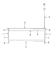
次に、添付図面に示した実施形態に基づき、本発明を更に詳細に説明する。図1〜図3は本発明に係る配線ダクトのコード類引出装置を備えたテーブルを示し、図4〜図10はその詳細を示し、図中符号1は脚体、2は天板、3はビーム、4は水平配線ダクト、5は柱状配線ダクト、10はダクト開口、12はダクトカバーをそれぞれ示している。尚、本発明はデスクであっても、何ら変更することなく、適用可能である。 Next, the present invention will be described in more detail based on the embodiments shown in the accompanying drawings. 1 to 3 show a table provided with a cord drawing device for a wiring duct according to the present invention, FIG. 4 to FIG. 10 show the details, in which 1 is a leg, 2 is a top plate, 3 is The beam, 4 is a horizontal wiring duct, 5 is a columnar wiring duct, 10 is a duct opening, and 12 is a duct cover. Note that the present invention can be applied to a desk without any changes.
本実施形態のテーブルは、両側に配した脚体1,1の下部間にビーム3を連結するとともに、上端部間に水平配線ダクト4を構成するダクト本体杆6を連結し、前記脚体1,1と該ダクト本体杆6とで天板2を支持する構造である。前記脚体1は、垂直な脚柱7の下端に接地杆8を前後方向に固定するとともに、脚柱7の上端に水平杆9を固定した、側面視倒H字形の構造であり、前記脚柱7の下部と上端部の内面側にそれぞれ前記ビーム3とダクト本体杆6とを連結している。
The table of this embodiment connects the
本発明は、天井から天板上にコード類を配線するための柱状配線ダクト5と水平配線ダクト4とを備えたテーブル、デスクにおける配線装置であって、脚体1に支持された天板2の下方に前記水平配線ダクト4のダクト本体杆6を備えるとともに、該天板2の側端よりも中央寄りに前記水平配線ダクト4のダクト開口10を形成し、前記柱状配線ダクト5の下部を、前記ダクト開口10を通して前記ダクト本体杆6の終端部に固定して立設し、前記水平配線ダクト4と柱状配線ダクト5を連係してなるものである。
The present invention is a wiring device in a table or desk provided with
更に詳しくは、前記水平配線ダクト4のダクト本体杆6は、上方が開放された樋状長尺部材であり、前記両脚体1,1間に終端部を連結して該脚体1と共に前記天板2の下面を支持し、前記天板2に形成した単数又は複数の前記ダクト開口10,…が前記ダクト本体杆6の凹溝部11の上方に位置するようにしている。
More specifically, the duct main body 杆 6 of the
そして、前記各ダクト開口10には、ダクトカバー12を着脱自在に設けている。本実施形態では、前記天板2は木質系の材質を用い、前記ダクトカバー12も木質系の材質を用いて全体の外観性の統一を図っている。前記ダクト開口10の左右開口縁、即ち前記ダクト本体杆6の凹溝部11に沿った方向と交差する両開口縁と前記ダクトカバー12の両側端縁の間に、コード類を引き出すことが可能な挿通孔13,13を形成している。尚、前記ダクト開口10の前後縁と前記ダクトカバー12の前後縁との間は着脱のための僅かなクリアランスを設けただけであり、前記天板2とダクトカバー12の上面は略面一で実質的に連続している。
A
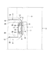
そして、図1、図4〜図9に示すように、前記ダクト本体杆6の終端部に前記脚体1の脚柱7の内面に連結する取付板14を有し、前記柱状配線ダクト5の下部を前記取付板14と前記脚体1の脚柱7の内面に共締めしている。ここで、前記柱状配線ダクト5は、内側面側にコード類を収容する凹溝16を有する柱部材15と、該凹溝16を塞ぐカバー部材17とから形成され、該柱部材15の下端部にはカバー部材17を設けないようにしている。前記柱部材15は、アルミ押出し型材からなり、前記カバー部材17は、合成樹脂製の押出し型材からなる。尚、前記柱部材15の強度が足らない場合には、前記凹溝16の内部に断面略コ字形のスチール製の補強部材を嵌着し、一体化する。
As shown in FIGS. 1 and 4 to 9, the end of the duct
前記柱状配線ダクト5の下部を前記取付板14と前記脚体1の脚柱7の内面に共締めする具体的な構造は、図4、図5、図8及び図9に示している。前記脚体1の脚柱7の上端部内面に、上下に複数の螺孔18,18を形成し、それぞれの螺孔18に締結ネジ19を螺合する。一方、前記ダクト本体杆6の取付板14と、前記柱状配線ダクト5の柱部材15の下部に、前記締結ネジ19に対応するように、それぞれダルマ孔20,20とダルマ孔21,21を形成している。ここで、前記ダルマ孔20,21は、前記締結ネジ19の頭部19Aを挿入する大径孔20A,21Aと、その上方に前記締結ネジ19の軸部19Bを受け入れ且つ頭部19Aより幅の狭い小径孔20B,21Bとを連続した形状である。そして、前記脚体1の脚柱7の内面に緩く螺合した前記締結ネジ19,19に、前記ダクト本体杆6の取付板14に形成したダルマ孔20,20をそれぞれ係止して仮連結し、それから該脚体1とダクト本体杆6に前記天板2を載置した状態で、前記ダクト開口10を通して挿入した前記柱状配線ダクト5の柱部材15に形成したダルマ孔21,21を前記締結ネジ19,19に係止した後、該締結ネジ19,19を本締めする。
A specific structure for fastening the lower part of the
それから、前記ダクト本体杆6の終端部に固定して立設した前記柱状配線ダクト5の外側面に、前記天板2の側端側のダクト開口10の側縁を当止し、その位置決め状態で、該天板2を下方から、前記脚体1の上端に設けた水平杆9と、ダクト本体杆6の両側上端に形成した補強鍔部22,22に、ネジ止めする。前記天板2の下面には、所定位置に予めオニメナット等を埋設して螺孔23,…を形成しておき、前記脚体1の水平杆9と前記ダクト本体杆6の補強鍔部22,22に形成した取付孔24,…に下方からネジ25,…を挿入して前記螺孔23,…に螺合する。ここで、前記天板2の下面は平面であるので、前記脚体1とダクト本体杆6に載置しただけでは、前記螺孔23と取付孔24の位置を合わせるのは難しいが、前述のようにダクト開口10の側縁と柱状配線ダクト5の外側面を位置決めの基準とすることにより、容易に位置決めができるのである。
Then, the side edge of the
本実施形態では、前記ダクト開口10は、前記天板2の前後中央部で左右方向の三箇所に形成している。そして、前記天板2の一側端側のダクト開口10の外側端部に前記柱状配線ダクト5が位置している。前記ダクトカバー12は、前記柱状配線ダクト5を立起状態で装着した状態でも前記ダクト開口10に装着することができるようになっている。その場合にも、中央寄りの他側には前記挿通孔13が形成される。
In the present embodiment, the
前記ダクト本体杆6は、スチール製で作製されており、前記凹溝部11の横幅よりも前記ダクト開口10の前後幅を広く設定し、該ダクト開口10の内部の前後部に前記補強鍔部22,22が段状に位置し、この段状部26,26に前記ダクトカバー12の前後縁部を載置できるようになっている。前記段状部26,26の左右中央には係合孔27,27をそれぞれ形成し、前記ダクトカバー12の裏面の左右中央の前後縁部に突設したピン28,28を前記係合孔27,27に係入することにより、ダクト開口10の内部の正確な位置に当該ダクトカバー12を装着できるようにしている。更に、前記ダクトカバー12の裏面の四隅部分にはマグネット29,…を埋設し、前記段状部26,26に吸着して当該ダクトカバー12を保持するようにしている。つまり、スチール製の前記段状部26,26が磁性材料となる。前記ダクトカバー12をダクト開口10から外すには、前記挿通孔13から指を挿入して該ダクトカバー12の一側部を持ち上げれば、前記マグネット29,…が前記補強鍔部22,22から離れると同時に、前記ピン28,28が補強鍔部22,22の係合孔27,27から抜ける。尚、前記ダクト本体杆6がスチール製でない場合には、前記段状部26,26に鉄片などの磁性材料を別途固定すればよい。
The
本発明において係着手段とは、前記ピン28と係合孔27との係合構造、あるいは前記マグネット29と前記段状部26,26が磁性材料との吸着構造、あるいは両者を併用した構造とする。
In the present invention, the engagement means means an engagement structure between the
ここで、前記ダクトカバー12は、左右対称形にすれば、前記ダクト開口10に装着する際に向きを間違えることがなく、また左右両側に形成られる挿通孔13,13の幅が同じになり、外観的にも好ましくなる。そして、前記柱状配線ダクト5が、前記挿通孔13に収まるように構成すれば、全てのダクト開口10とダクトカバー12を共通の形状にすることができる。
Here, if the
前述のように、前記脚体1の脚柱7の内面に緩く螺合した締結ネジ19,19に、前記ダクト本体杆6の取付板14に形成したダルマ孔20,20と前記柱状配線ダクト5の柱部材15に形成したダルマ孔21,21を係止して仮連結した後、前記締結ネジ19,19を本締めするが、このとき電動ドライバーを使用できるように、前記ダクト本体杆6の凹溝部11の横幅と、前記ダクト開口10の左右方向の長さに、十分に余裕を持たせている。本実施形態では、前記凹溝部11の横幅は、約70mmであり、前記ダクト開口10は100mm×400mmに設定している。このようにすれば、電動ドライバーをダクト開口10から前記凹溝部11内に挿入し、前記締結ネジ19,19を軸方向から回転させることができる。
As described above, the fastening screws 19 and 19 which are loosely screwed into the inner surface of the
前記柱状配線ダクト5の柱部材15は、図4及び図6に示すように、凹溝16内の両側に係止条部30,30を形成し、両係止条部30,30に前記カバー部材17の両側の脚片31,31を係脱可能に係合するようになっている。そして、前記凹溝16とカバー部材17とで、鉛直方向の閉じたダクト空間が形成される。尚、本実施形態では、前記係止条部30の外側にも前記カバー部材17で覆われない溝部が形成されており、前記ダクト空間に電源コード等の強電コード類を配線し、外側の溝部にLANケーブルや電話線等の弱電コード類を分離して配線することも可能である。勿論、全てのコード類を前記凹溝16とカバー部材17とで形成られたダクト空間に配線することも可能である。
As shown in FIGS. 4 and 6, the
そして、天井から前記柱状配線ダクト5にコード類を引き込むために、直接引き込んでも良いが、天井からのコード類と柱状配線ダクト5に配線するコード類をコネクタで接続することもあり、その場合にタップやプラグ等のコネクタ類を収容するための接続ボックス32が前記柱部材15の上端に固定されている。前記接続ボックス32は、図1〜図3に示すように、上方へ開放した台形状を有し、その内部に余剰コード類を収容しておくことも可能である。また、前記柱状配線ダクト5の下端部で、前記ダクト本体杆6の凹溝部11の内部に対応する部分には、前記カバー部材17を設けてなく、前記柱部材15の凹溝16を露出させている。こうすることによって、前記水平配線ダクト4と柱状配線ダクト5が連通し、天井から下ろしたコード類を、柱状配線ダクト5を通して水平配線ダクト4に配線し、前記ダクト開口10から天板2上に引き出すことができる。そして、前記ダクト開口10にダクトカバー12を装着した場合であっても、左右両側の挿通孔13,13の片方又は両方からコード類を引き出したままにできるのである。尚、前記ダクト開口10に対応するダクト本体杆6の底面には、開口33が設けられ、該開口33を通して下方へコード類を引き出すこともできるとうにしている。
In order to draw the cords from the ceiling to the
本発明に係るテーブルは、図1、図2、図5、図6及び図9に示すように、前記天板2の側端面よりも中央寄り位置に前記柱状配線ダクト5が立設されている。従って、前記天板2の側端を他のテーブルの天板の縁部に接合したり、壁面に接合する場合でも、前記柱状配線ダクト5が邪魔になることはない。更に、前記柱状配線ダクト5よりも側方の天板2の側部を積極的に利用できるように、前記脚体1から側方へ突出する長さを大きくして、側部に着座した使用者も余裕を持って天板2を利用できるようにすることも好ましい。更に、前記天板2の側部を半円状に側方へ突出させることも好ましい。このように、前記天板2の形状を自由に設定できるので、前記柱状配線ダクト5を天板2の側端よりも中央より寄り位置に設けたダクト開口10の内部を利用して立設したからである。
As shown in FIGS. 1, 2, 5, 6 and 9, the table according to the present invention has the
1 脚体、 2 天板、
3 ビーム、 4 水平配線ダクト、
5 柱状配線ダクト、 6 ダクト本体杆、
7 脚柱、 8 接地杆、
9 水平杆、 10 ダクト開口、
11 凹溝部、 12 ダクトカバー、
13 挿通孔、 14 取付板、
15 柱部材、 16 凹溝、
17 カバー部材、 18 螺孔、
19 締結ネジ、 19A 頭部、
19B 軸部、 20 ダルマ孔、
21 ダルマ孔、 20A,21A 大径孔、
20B,21B 小径孔、 22 補強鍔部、
23 螺孔、 24 取付孔、
25 ネジ、 26 段状部、
27 係合孔、 28 ピン、
29 マグネット、 30 係止条部、
31 脚片、 32 接続ボックス、
33 開口。
1 leg, 2 top plate,
3 beam, 4 horizontal wiring duct,
5
7 pedestal, 8 grounding rod,
9 horizontal fence, 10 duct opening,
11 concave groove, 12 duct cover,
13 insertion hole, 14 mounting plate,
15 column member, 16 groove,
17 cover member, 18 screw hole,
19 fastening screws, 19A head,
19B Shaft, 20 Dharma hole,
21 Dharma hole, 20A, 21A large diameter hole,
20B, 21B small-diameter hole, 22 reinforcing collar,
23 screw holes, 24 mounting holes,
25 screws, 26 steps,
27 engagement holes, 28 pins,
29 magnets, 30 locking strips,
31 leg pieces, 32 connection boxes,
33 Opening.
Claims (5)
Priority Applications (1)
| Application Number | Priority Date | Filing Date | Title |
|---|---|---|---|
| JP2012089158A JP5880236B2 (en) | 2012-04-10 | 2012-04-10 | Wire duct cord drawing device |
Applications Claiming Priority (1)
| Application Number | Priority Date | Filing Date | Title |
|---|---|---|---|
| JP2012089158A JP5880236B2 (en) | 2012-04-10 | 2012-04-10 | Wire duct cord drawing device |
Publications (2)
| Publication Number | Publication Date |
|---|---|
| JP2013215424A true JP2013215424A (en) | 2013-10-24 |
| JP5880236B2 JP5880236B2 (en) | 2016-03-08 |
Family
ID=49588304
Family Applications (1)
| Application Number | Title | Priority Date | Filing Date |
|---|---|---|---|
| JP2012089158A Active JP5880236B2 (en) | 2012-04-10 | 2012-04-10 | Wire duct cord drawing device |
Country Status (1)
| Country | Link |
|---|---|
| JP (1) | JP5880236B2 (en) |
Cited By (4)
| Publication number | Priority date | Publication date | Assignee | Title |
|---|---|---|---|---|
| JP2017093925A (en) * | 2015-11-26 | 2017-06-01 | コクヨ株式会社 | shelf |
| JP2017099736A (en) * | 2015-12-03 | 2017-06-08 | コクヨ株式会社 | Furniture with frame |
| CN107877131A (en) * | 2017-12-13 | 2018-04-06 | 金子电线电讯(苏州)有限公司 | A kind of microtubular inner tube pulling device |
| JP2018068906A (en) * | 2016-11-02 | 2018-05-10 | 株式会社岡村製作所 | Wiring housing furniture |
Citations (3)
| Publication number | Priority date | Publication date | Assignee | Title |
|---|---|---|---|---|
| JPS57124217U (en) * | 1981-01-29 | 1982-08-03 | ||
| JP2001128745A (en) * | 1999-11-05 | 2001-05-15 | Okamura Corp | Structure of wiring duct of table |
| JP2006026429A (en) * | 2005-08-31 | 2006-02-02 | Ebisuya Kogyo Kk | Receptacle |
-
2012
- 2012-04-10 JP JP2012089158A patent/JP5880236B2/en active Active
Patent Citations (3)
| Publication number | Priority date | Publication date | Assignee | Title |
|---|---|---|---|---|
| JPS57124217U (en) * | 1981-01-29 | 1982-08-03 | ||
| JP2001128745A (en) * | 1999-11-05 | 2001-05-15 | Okamura Corp | Structure of wiring duct of table |
| JP2006026429A (en) * | 2005-08-31 | 2006-02-02 | Ebisuya Kogyo Kk | Receptacle |
Cited By (4)
| Publication number | Priority date | Publication date | Assignee | Title |
|---|---|---|---|---|
| JP2017093925A (en) * | 2015-11-26 | 2017-06-01 | コクヨ株式会社 | shelf |
| JP2017099736A (en) * | 2015-12-03 | 2017-06-08 | コクヨ株式会社 | Furniture with frame |
| JP2018068906A (en) * | 2016-11-02 | 2018-05-10 | 株式会社岡村製作所 | Wiring housing furniture |
| CN107877131A (en) * | 2017-12-13 | 2018-04-06 | 金子电线电讯(苏州)有限公司 | A kind of microtubular inner tube pulling device |
Also Published As
| Publication number | Publication date |
|---|---|
| JP5880236B2 (en) | 2016-03-08 |
Similar Documents
| Publication | Publication Date | Title |
|---|---|---|
| US10907806B2 (en) | Lighting fixture with multiple configurations for different junction box configurations | |
| JP5880236B2 (en) | Wire duct cord drawing device | |
| KR200480539Y1 (en) | Integrated raceway device having wire distribution | |
| JP5796178B2 (en) | Floor wiring equipment | |
| JP5780198B2 (en) | Wiring device for table and desk | |
| JP2007209386A (en) | Fixing structure of mirror | |
| JP2020065877A (en) | Article stand | |
| WO2018196773A1 (en) | Indoor unit and air conditioner having same | |
| JP6163764B2 (en) | Table wiring duct equipment | |
| JP2013121270A (en) | Wiring duct device of post | |
| JP2014061195A (en) | At-hand wiring device of table | |
| CN205557960U (en) | Aluminum plate sitting room suspended ceiling system | |
| JP2011249473A (en) | Electronic device housing | |
| JP5147118B2 (en) | lighting equipment | |
| JP6541062B2 (en) | lighting equipment | |
| JP2018153038A (en) | Assembly structure of decoration member | |
| KR200474889Y1 (en) | Illumination installation equipped in high ceiling with convenient and safe lamp replacement and management | |
| JP6308648B2 (en) | Table fixtures and table equipment | |
| JP4450360B2 (en) | Wiring cover configuration | |
| JP2010022172A (en) | High airtight separate structure | |
| KR200480308Y1 (en) | Pedal board for electric guitar | |
| JP2005273280A (en) | Partition wall structure | |
| JP2013121295A (en) | Wiring cover device of horizontal beam | |
| JP6206813B2 (en) | Wiring fixture mounting device | |
| JP2016096282A (en) | Box for housing electric apparatus |
Legal Events
| Date | Code | Title | Description |
|---|---|---|---|
| A621 | Written request for application examination |
Free format text: JAPANESE INTERMEDIATE CODE: A621 Effective date: 20141227 |
|
| A977 | Report on retrieval |
Free format text: JAPANESE INTERMEDIATE CODE: A971007 Effective date: 20150420 |
|
| A131 | Notification of reasons for refusal |
Free format text: JAPANESE INTERMEDIATE CODE: A131 Effective date: 20150519 |
|
| A521 | Written amendment |
Free format text: JAPANESE INTERMEDIATE CODE: A523 Effective date: 20150717 |
|
| TRDD | Decision of grant or rejection written | ||
| A01 | Written decision to grant a patent or to grant a registration (utility model) |
Free format text: JAPANESE INTERMEDIATE CODE: A01 Effective date: 20160105 |
|
| A61 | First payment of annual fees (during grant procedure) |
Free format text: JAPANESE INTERMEDIATE CODE: A61 Effective date: 20160118 |
|
| R150 | Certificate of patent or registration of utility model |
Ref document number: 5880236 Country of ref document: JP Free format text: JAPANESE INTERMEDIATE CODE: R150 |
|
| S531 | Written request for registration of change of domicile |
Free format text: JAPANESE INTERMEDIATE CODE: R313531 |
|
| R350 | Written notification of registration of transfer |
Free format text: JAPANESE INTERMEDIATE CODE: R350 |