JP2013215388A - Absorbent article - Google Patents
Absorbent article Download PDFInfo
- Publication number
- JP2013215388A JP2013215388A JP2012088358A JP2012088358A JP2013215388A JP 2013215388 A JP2013215388 A JP 2013215388A JP 2012088358 A JP2012088358 A JP 2012088358A JP 2012088358 A JP2012088358 A JP 2012088358A JP 2013215388 A JP2013215388 A JP 2013215388A
- Authority
- JP
- Japan
- Prior art keywords
- longitudinal
- width direction
- absorbent article
- width
- pressing
- Prior art date
- Legal status (The legal status is an assumption and is not a legal conclusion. Google has not performed a legal analysis and makes no representation as to the accuracy of the status listed.)
- Pending
Links
Images


Classifications
-
- A—HUMAN NECESSITIES
- A61—MEDICAL OR VETERINARY SCIENCE; HYGIENE
- A61F—FILTERS IMPLANTABLE INTO BLOOD VESSELS; PROSTHESES; DEVICES PROVIDING PATENCY TO, OR PREVENTING COLLAPSING OF, TUBULAR STRUCTURES OF THE BODY, e.g. STENTS; ORTHOPAEDIC, NURSING OR CONTRACEPTIVE DEVICES; FOMENTATION; TREATMENT OR PROTECTION OF EYES OR EARS; BANDAGES, DRESSINGS OR ABSORBENT PADS; FIRST-AID KITS
- A61F13/00—Bandages or dressings; Absorbent pads
- A61F13/15—Absorbent pads, e.g. sanitary towels, swabs or tampons for external or internal application to the body; Supporting or fastening means therefor; Tampon applicators
- A61F13/51—Absorbent pads, e.g. sanitary towels, swabs or tampons for external or internal application to the body; Supporting or fastening means therefor; Tampon applicators characterised by the outer layers
- A61F13/511—Topsheet, i.e. the permeable cover or layer facing the skin
- A61F13/51104—Topsheet, i.e. the permeable cover or layer facing the skin the top sheet having a three-dimensional cross-section, e.g. corrugations, embossments, recesses or projections
-
- A—HUMAN NECESSITIES
- A61—MEDICAL OR VETERINARY SCIENCE; HYGIENE
- A61F—FILTERS IMPLANTABLE INTO BLOOD VESSELS; PROSTHESES; DEVICES PROVIDING PATENCY TO, OR PREVENTING COLLAPSING OF, TUBULAR STRUCTURES OF THE BODY, e.g. STENTS; ORTHOPAEDIC, NURSING OR CONTRACEPTIVE DEVICES; FOMENTATION; TREATMENT OR PROTECTION OF EYES OR EARS; BANDAGES, DRESSINGS OR ABSORBENT PADS; FIRST-AID KITS
- A61F13/00—Bandages or dressings; Absorbent pads
- A61F13/15—Absorbent pads, e.g. sanitary towels, swabs or tampons for external or internal application to the body; Supporting or fastening means therefor; Tampon applicators
- A61F13/45—Absorbent pads, e.g. sanitary towels, swabs or tampons for external or internal application to the body; Supporting or fastening means therefor; Tampon applicators characterised by the shape
- A61F13/47—Sanitary towels, incontinence pads or napkins
- A61F13/4704—Sanitary towels, incontinence pads or napkins having preferential bending zones, e.g. fold lines or grooves
-
- A—HUMAN NECESSITIES
- A61—MEDICAL OR VETERINARY SCIENCE; HYGIENE
- A61F—FILTERS IMPLANTABLE INTO BLOOD VESSELS; PROSTHESES; DEVICES PROVIDING PATENCY TO, OR PREVENTING COLLAPSING OF, TUBULAR STRUCTURES OF THE BODY, e.g. STENTS; ORTHOPAEDIC, NURSING OR CONTRACEPTIVE DEVICES; FOMENTATION; TREATMENT OR PROTECTION OF EYES OR EARS; BANDAGES, DRESSINGS OR ABSORBENT PADS; FIRST-AID KITS
- A61F13/00—Bandages or dressings; Absorbent pads
- A61F13/15—Absorbent pads, e.g. sanitary towels, swabs or tampons for external or internal application to the body; Supporting or fastening means therefor; Tampon applicators
- A61F13/53—Absorbent pads, e.g. sanitary towels, swabs or tampons for external or internal application to the body; Supporting or fastening means therefor; Tampon applicators characterised by the absorbing medium
- A61F13/531—Absorbent pads, e.g. sanitary towels, swabs or tampons for external or internal application to the body; Supporting or fastening means therefor; Tampon applicators characterised by the absorbing medium having a homogeneous composition through the thickness of the pad
- A61F13/532—Absorbent pads, e.g. sanitary towels, swabs or tampons for external or internal application to the body; Supporting or fastening means therefor; Tampon applicators characterised by the absorbing medium having a homogeneous composition through the thickness of the pad inhomogeneous in the plane of the pad
- A61F13/533—Absorbent pads, e.g. sanitary towels, swabs or tampons for external or internal application to the body; Supporting or fastening means therefor; Tampon applicators characterised by the absorbing medium having a homogeneous composition through the thickness of the pad inhomogeneous in the plane of the pad having discontinuous areas of compression
-
- A—HUMAN NECESSITIES
- A61—MEDICAL OR VETERINARY SCIENCE; HYGIENE
- A61F—FILTERS IMPLANTABLE INTO BLOOD VESSELS; PROSTHESES; DEVICES PROVIDING PATENCY TO, OR PREVENTING COLLAPSING OF, TUBULAR STRUCTURES OF THE BODY, e.g. STENTS; ORTHOPAEDIC, NURSING OR CONTRACEPTIVE DEVICES; FOMENTATION; TREATMENT OR PROTECTION OF EYES OR EARS; BANDAGES, DRESSINGS OR ABSORBENT PADS; FIRST-AID KITS
- A61F13/00—Bandages or dressings; Absorbent pads
- A61F13/15—Absorbent pads, e.g. sanitary towels, swabs or tampons for external or internal application to the body; Supporting or fastening means therefor; Tampon applicators
- A61F13/51—Absorbent pads, e.g. sanitary towels, swabs or tampons for external or internal application to the body; Supporting or fastening means therefor; Tampon applicators characterised by the outer layers
- A61F2013/51078—Absorbent pads, e.g. sanitary towels, swabs or tampons for external or internal application to the body; Supporting or fastening means therefor; Tampon applicators characterised by the outer layers being embossed
Abstract
Description
本発明は、生理用ナプキン等の吸収性物品に関する。 The present invention relates to an absorbent article such as a sanitary napkin.
特許文献1及び特許文献2には、液透過性の表面シートと、液不透過性の裏面シートと、表面シートと裏面シートとの間に配置される吸収体とを有する吸収性物品としての生理用ナプキンが記載されている。特許文献1の吸収性物品には、表面シートと吸収体とが厚み方向に圧縮されたチャネルが形成されている。チャネルは、着用者の排泄口に当接する排泄口当接領域を囲むように環状に形成されている。 In Patent Document 1 and Patent Document 2, a physiological article as an absorbent article having a liquid-permeable top sheet, a liquid-impermeable back sheet, and an absorbent body disposed between the top sheet and the back sheet. A napkin for use is described. In the absorbent article of Patent Document 1, a channel in which a top sheet and an absorbent body are compressed in the thickness direction is formed. The channel is formed in an annular shape so as to surround an excretion opening contact area that contacts the excretion opening of the wearer.
また、特許文献2の吸収性物品は、表面シートと吸収体とが厚み方向に圧縮された可撓軸を有する生理用ナプキンが記載されている。可撓軸は、排泄口当接領域の幅方向両外側において、幅方向内側に向かって突出する円弧状に形成されている。 Further, the absorbent article of Patent Document 2 describes a sanitary napkin having a flexible shaft in which a top sheet and an absorbent body are compressed in the thickness direction. The flexible shaft is formed in an arc shape projecting inward in the width direction on both outer sides in the width direction of the excretory opening contact region.
吸収体の排泄口当接領域は、着用者に装着された状態で着用者の股下に位置し、着用者の脚の間に挟まれるように配置される。着用者の脚等によって吸収体が挟まれて幅方向外側から幅方向内側に向かって力が掛けられることにより、環状のチャネル又は可撓軸が内方向に向かって変形する。 The excretory opening contact region of the absorber is positioned so as to be sandwiched between the legs of the wearer while being placed on the wearer's crotch while being worn by the wearer. The absorbent body is sandwiched between the legs of the wearer and a force is applied from the outer side in the width direction toward the inner side in the width direction, whereby the annular channel or the flexible shaft is deformed inward.
しかし、上述の吸収性物品には、以下の問題があった。
例えば、特許文献1に記載の排泄口当接領域は、楕円形の環状のチャネルによって囲まれており、排泄口当接領域全体がチャネルによって内方向に圧縮されることにより、排泄口当接領域の幅が短くなることがある。
However, the above absorbent article has the following problems.
For example, the excretory opening contact area described in Patent Document 1 is surrounded by an elliptical annular channel, and the entire excretion opening contact area is compressed inward by the channel, whereby the excretion opening contact area The width may be shortened.
また、特許文献2に記載の吸収性物品は、一対の可撓軸の円弧状が1カ所であり、一対の可撓軸間の距離が排泄口当接領域の長手方向中央部において最も短くなっている。よって、排泄口当接領域の長手方向中央に応力が集中し、排泄口当接領域の長手方向中央の幅が短くなり易い。このように、排泄口当接領域の幅が局所的に短くなると、排泄口に対向して吸収体を配置できず、体液の漏れが発生するおそれがある。また、長手方向において吸収性物品の装着位置がずれると、一対の可撓軸間の距離が短くなる部分が排泄口当接領域に対応して配置されず、フィット性が向上しないことがある。 Further, in the absorbent article described in Patent Document 2, the arc shape of the pair of flexible shafts is one place, and the distance between the pair of flexible shafts is the shortest in the central portion in the longitudinal direction of the excretory opening contact region. ing. Therefore, stress concentrates on the center in the longitudinal direction of the excretory opening contact area, and the width of the center in the longitudinal direction of the excretion opening contact area tends to be short. Thus, when the width | variety of an excretion opening | mouth contact area | region becomes short locally, an absorber cannot be arrange | positioned facing an excretion opening | mouth, and there exists a possibility that the leakage of a bodily fluid may generate | occur | produce. Moreover, if the mounting position of the absorbent article is shifted in the longitudinal direction, the portion where the distance between the pair of flexible shafts is shortened is not arranged corresponding to the excretory opening contact region, and the fit may not be improved.
また、近年、開発途上国や新興国においても、吸収性物品が普及してきている。本出願人が開発途上国等における使用態様を調査した結果、普及し始めたばかり国においては、吸収性物品を持ち歩くことに抵抗を感じる着用者が存在することがわかった。また、吸収性物品を持ち歩くことに抵抗がない着用者であっても、外出先において吸収性物品を交換する環境が整っていなかったり、捨てる場所がなかったりして、吸収性物品を適宜交換できない着用者が存在することがわかった。このような着用者は、吸収性物品を持ち歩いて適宜交換する着用者に比べて、日中における装着時間が長くなる。 In recent years, absorbent articles have become popular in developing and emerging countries. As a result of investigating the use modes in developing countries and the like by the present applicant, it has been found that there are wearers who feel resistance to carrying absorbent articles in countries that have just started to spread. Moreover, even if the wearer has no resistance to carrying the absorbent article, the absorbent article cannot be properly replaced because the environment for exchanging the absorbent article is not in place or there is no place to throw it away. It was found that there was a wearer. Such a wearer has a longer wearing time during the day than a wearer who carries an absorbent article and replaces it appropriately.
日中の装着時間が長くなると、歩行時等に脚によって挟まれる回数が増え、繰り返し吸収体が幅方向内側に圧縮される。吸収性物品が繰り返し幅方向内側に圧縮されると、吸収体の幅が更に短くなり、排泄口に対向する位置に吸収体が配置されなかったり、吸収体が硬化したりするおそれがある。このように、排泄口に対向して吸収体が配置されないと、体液の漏れが発生するおそれがある。また、吸収体の排泄口当接領域が硬化すると、装着感が悪化したり、フィット性が低下したりするおそれがある。 If the wearing time during the day becomes long, the number of times that the body is pinched by the legs during walking increases, and the absorbent body is repeatedly compressed inward in the width direction. When the absorbent article is repeatedly compressed inward in the width direction, the width of the absorbent body is further shortened, and the absorbent body may not be disposed at a position facing the excretion opening, or the absorbent body may be cured. Thus, if the absorbent body is not disposed facing the excretion opening, there is a possibility that body fluid leaks. Moreover, when the excretion opening | mouth contact | abutting area | region of an absorber hardens | cures, there exists a possibility that a feeling of mounting may deteriorate or a fitting property may fall.
そこで、本発明は、上述の課題に鑑みてなされたものであり、吸収性物品の耐久性を向上させて、日中に長時間使用した場合であっても、吸収性能を確保しつつ、フィット性や装着感を向上させることができる吸収性物品を提供することを目的とする。 Therefore, the present invention has been made in view of the above-described problems, and improves the durability of the absorbent article, and even when used for a long time during the day, the absorption performance is secured while being fit. It aims at providing the absorbent article which can improve a property and a feeling of wearing.
上述した課題を解決するため、本発明に係る吸収性物品は、液透過性の表面シート(表面シート10)、液不透過性の裏面シート(裏面シート20)、及び前記表面シートと前記裏面シートとの間に配置される吸収体(吸収体30)を有し、前記表面シートと前記吸収体とを前記吸収性物品の厚み方向に圧縮した圧搾部が形成された吸収性物品(吸収性物品1)であって、前記圧搾部は、着用者の排泄口に対向して配置される排泄口当接領域の中心を含む中央領域(中央領域CA)よりも前記吸収性物品の幅方向両外側に配置され、かつ前記吸収性物品の長手方向に延びる一対の第1長手圧搾部(第1長手圧搾部81)と、前記第1長手圧搾部よりも前記幅方向両外側に配置され、かつ前記長手方向に延びる一対の第2長手圧搾部(第2長手圧搾部82)と、を備えており、前記第2長手圧搾部には、前記幅方向外側に向かう凸形状を有する曲線部(第2曲線部86)が長手方向に連続して複数設けられており、曲線部の長手方向の端部(第2曲線部86の長手方向端部86L)は、前記中央領域の前記長手方向中心を通り、かつ幅方向に沿った中心ライン(中心ラインCACL)上に設けられており、前記各曲線部の長手方向における端部は、前記各曲線部の幅方向における外側端部よりも幅方向内側に配置されていることを要旨とする。
In order to solve the above-described problems, an absorbent article according to the present invention includes a liquid-permeable top sheet (top sheet 10), a liquid-impermeable back sheet (back sheet 20), and the top sheet and the back sheet. An absorbent article (absorbent article) in which a compressed portion is formed by compressing the topsheet and the absorbent body in the thickness direction of the absorbent article. 1) Comprising: The said compression part is the width direction both outer sides of the said absorbent article rather than the center area | region (central area | region CA) containing the center of the excretion opening | mouth contact | abutting area | region arrange | positioned facing a wearer's excretion opening | mouth. And a pair of first longitudinal pressing parts (first longitudinal pressing part 81) extending in the longitudinal direction of the absorbent article, and arranged on both outer sides in the width direction than the first longitudinal pressing part, and A pair of second longitudinal pressing parts (second longitudinal direction) extending in the longitudinal direction Squeezed portion 82), and a plurality of curved portions (second curved portion 86) having a convex shape toward the outer side in the width direction are continuously provided in the second longitudinal compressed portion in the longitudinal direction. In addition, an end portion in the longitudinal direction of the curved portion (
本開示に係る吸収性物品によれば、吸収性物品の耐久性を向上させて、日中に長時間使用した場合であっても、吸収性能を確保しつつ、フィット性や装着感を向上させることができる吸収性物品を提供する According to the absorbent article according to the present disclosure, the durability of the absorbent article is improved, and even when used for a long time during the day, the absorption performance is ensured and the fit and the feeling of wearing are improved. Provide an absorbent article that can
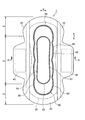
図面を参照して、実施形態に係る吸収性物品1について説明する。図1は、吸収性物品の平面図であり、図2は、図1に示すA−A断面図である。本実施形態に係る吸収性物品1は、例えば、生理用ナプキンである。 With reference to drawings, the absorbent article 1 which concerns on embodiment is demonstrated. FIG. 1 is a plan view of the absorbent article, and FIG. 2 is a cross-sectional view taken along line AA shown in FIG. The absorbent article 1 according to the present embodiment is, for example, a sanitary napkin.
実施の形態に係る吸収性物品は、昼用の生理用ナプキンである。したがって、本実施の形態に係る吸収性物品は、長手方向において着用者の前側に位置する前側領域FAと、着用者の後側に位置する後側領域BAとの長さが略同じである。 The absorbent article according to the embodiment is a daytime sanitary napkin. Therefore, in the absorbent article according to the present embodiment, the lengths of the front area FA located on the front side of the wearer in the longitudinal direction and the rear area BA located on the rear side of the wearer are substantially the same.
なお、後述する一対のウイング部の間の領域は、着用者の排泄口が当接する排泄口当接領域を含む中央領域CAである。中央領域CAよりも前側が前側領域FAとなり、中央領域CAよりも後側が後側領域BAとなる。 In addition, the area | region between a pair of wing parts mentioned later is center area | region CA containing the excretion opening | mouth contact | abutting area | region where a wearer's excretion opening contacts. A front side of the central area CA is a front side area FA, and a rear side of the central area CA is a rear side area BA.
なお、本実施の形態では、昼用の生理用ナプキンを例に挙げて説明しているが、本発明に係る吸収性物品は、夜用の生理用ナプキンにおいても適用することができる。夜用の生理用ナプキンは、長手方向において着用者の前側に位置する前側領域FAよりも、着用者の後側に位置する後側領域BAの方が長く構成されている。 In the present embodiment, a daytime sanitary napkin is described as an example, but the absorbent article according to the present invention can also be applied to a night sanitary napkin. The night sanitary napkin is configured such that the rear area BA located on the rear side of the wearer is longer than the front area FA located on the front side of the wearer in the longitudinal direction.
吸収性物品1は、着用者の肌に当接する表面シート10と、液体を透過しない液不透過性の裏面シート20と、吸収体30とを有する。吸収体30は、表面シート10と裏面シート20との間に配設される。従って、吸収体30は、図1及び図2において破線で示される。吸収体30は、吸収性物品1の長手方向L及び幅方向Wにおける中央部分に配設される。
The absorbent article 1 includes a
吸収性物品1は、図1に示す平面視にて、長手方向Lに直交する幅方向Wにおいて吸収体30の外側に設けられるウイング部43,44を備える。更に、吸収性物品1は、幅方向Wにおいて吸収体30の外側に設けられるサイドシート41,42を備える。
The absorbent article 1 includes
表面シート10は、体液等の液体を透過する液透過性のシートである。表面シート10は、少なくとも吸収体30の表面を覆う。表面シート10は、不織布、織布、有孔プラスチックシート、メッシュシート等、液体を透過する構造のシート状の材料であれば、特に限定されない。織布や不織布の素材としては、天然繊維、化学繊維のいずれも使用できる。
The
天然繊維の例としては、粉砕パルプ、コットン等のセルロースが挙げられる。化学繊維の例としては、レーヨン、フィブリルレーヨン等の再生セルロース、アセテート、トリアセテート等の半合成セルロース、熱可塑性疎水性化学繊維、もしくは親水化処理を施した熱可塑性疎水性化学繊維が挙げられる。 Examples of natural fibers include cellulose such as pulverized pulp and cotton. Examples of the chemical fiber include regenerated cellulose such as rayon and fibril rayon, semi-synthetic cellulose such as acetate and triacetate, thermoplastic hydrophobic chemical fiber, and thermoplastic hydrophobic chemical fiber subjected to hydrophilic treatment.
前記熱可塑性疎水性化学繊維としては、ポリエチレン(PE)、ポリプロピレン(PP)、ポリエチレンテレフタレート(PET)等の単繊維、PEとPPをグラフト重合してなる繊維、芯鞘構造等の複合繊維が例として挙げられる。 Examples of the thermoplastic hydrophobic chemical fibers include single fibers such as polyethylene (PE), polypropylene (PP), and polyethylene terephthalate (PET), fibers obtained by graft polymerization of PE and PP, and composite fibers such as a core-sheath structure. As mentioned.
なお、特に不織布には、ウェブフォーミングは、乾式(カード法、スパンボンド法メルトブローン法、エアレイド法等)や湿式等のいずれか、又は複数を組み合わせて行ってもよい。また、ボンディングの方法としては、サーマルボンディング、ニードルパンチ、ケミカルボンディング等の方法が挙げられるが、特にこれらの方法に限定されるものではない。また、水流交絡法によりシート状に形成したスパンレースを用いても良い。 In particular, for non-woven fabrics, web forming may be performed by any of dry methods (card method, spun bond method melt blown method, air laid method, etc.), wet methods, or a combination of a plurality of them. Examples of bonding methods include thermal bonding, needle punching, chemical bonding, and the like, but are not particularly limited to these methods. Moreover, you may use the spunlace formed in the sheet form by the hydroentanglement method.
有孔プラスチックシートとしては、PE、PP、PETといった熱可塑性樹脂の有孔シートや、多孔質の発泡材等を用いることができる。また、これらについては必要に応じて酸化チタンや炭酸カルシウム等からなるフィラーを0.5〜10%の範囲で混入することにより、白濁化させて使用することも好ましい。また、前記熱可塑性樹脂からなるフィルムを、パーフォレーション、ヒートエンボス加工、或いは機械加工等により開孔した有孔フィルムを使用しても良い。有孔フィルムは、不織布との複合シートとして使用しても良い。 As the perforated plastic sheet, a perforated sheet of a thermoplastic resin such as PE, PP, and PET, a porous foam material, or the like can be used. Moreover, about these, it is also preferable to make it cloudy by mixing the filler which consists of a titanium oxide, a calcium carbonate, etc. in the range of 0.5 to 10% as needed. Moreover, you may use the perforated film which opened the film which consists of the said thermoplastic resin by perforation, heat embossing, or machining. The perforated film may be used as a composite sheet with a nonwoven fabric.
裏面シート20は、表面シート10の長さと略同一の長さを有する。裏面シート20は、ポリエチレンシート、ポリプロピレン等を主体としたラミネート不織布、通気性の樹脂フィルム、スパンボンド、又はスパンレース等の不織布に通気性の樹脂フィルムが接合されたシートなどを用いることができる。裏面シート20は、着用時の違和感を生じさせない程度の柔軟性を有する材料とすることが好ましく、例えば低密度ポリエチレン(LDPE)樹脂を主体とした目付15〜30g/m2の範囲から得られるフィルムを用いることができる。裏面シート20は、不透液性且つ透湿性であることが望ましく、例えばポリエチレンやポリプロピレン等のオレフィン系樹脂に無機充填剤を溶融混練したものを延伸処理した微多孔性シートによって構成することができる。
The
吸収体30は、親水性繊維、パルプを含む。吸収体30は、経血などの体液を吸収可能な材料によって形成される。例として、粉砕パルプ、コットン等のセルロース、レーヨン、フィブリルレーヨン等の再生セルロース、アセテート、トリアセテート等の半合成セルロース、粒子状ポリマー、繊維状ポリマー、熱可塑性疎水性化学繊維、もしくは親水化処理を施した熱可塑性疎水性化学繊維、ケミカルボンド処理されたエアレイドパルプ等を単独又は混合して用いることができる。
The
これらの材料を吸収体に成形する方法は特に限定されるものではないが、例えばエアレイド法、メルトブローン法、スパンレース法、抄紙法等によってシート化したものが使用される。また、吸収体としてセルロース発泡体、合成樹脂の連続発泡体等も使用することができる。さらに、発泡体又は前記シート化した材料を粉砕した後に吸収体に成形したものを使用することも可能である。これらの中でも、パルプを80〜100%の範囲、粒子状ポリマーを20〜0%の範囲で混合し、テッィシュで被覆した後、エンボス加工によりシート化した目付100〜2000g/m2、1〜50mmの嵩を有する吸収体が挙げられる。エンボス加工は吸収体の型崩れを防止するためであり、エンボス面積率は10〜100%の範囲、好ましくは30〜80%の範囲である。 The method for forming these materials into the absorbent body is not particularly limited, but for example, a sheet formed by an airlaid method, a meltblown method, a spunlace method, a papermaking method or the like is used. Moreover, a cellulose foam, a synthetic resin continuous foam, etc. can also be used as an absorber. Furthermore, it is also possible to use what was formed into an absorber after pulverizing the foam or the sheeted material. Among these, pulp is mixed in the range of 80 to 100%, particulate polymer is mixed in the range of 20 to 0%, coated with tissue, and then sheeted by embossing to have a basis weight of 100 to 2000 g / m 2 , 1 to 50 mm The absorber which has the bulk of this is mentioned. Embossing is for preventing the shape of the absorber from being lost, and the embossed area ratio is in the range of 10 to 100%, preferably in the range of 30 to 80%.
吸収体30は、親水性繊維又は粉体をエアレイド法によって積層して形成されてもよいし、親水性繊維又は粉体をエアレイド法によってシート状に成形したエアレイドシートでもよいし、ティッシュ(例えば、目付15g/m2)上に高吸収ポリマーを混入した粉砕パルプを配置し、ティッシュで包むことによって形成されていてもよい。
The
さらには、薄型吸収体の材料の他の例としては、吸収シート及びポリマーシートが挙げられ、その厚さは、0.3〜5mmであるのが好ましい。この吸収シート及びポリマーシートとしては、通常、生理用ナプキンなどの吸収性物品に用いられるものであれば特に制限なく用いることができる。 Furthermore, other examples of the material of the thin absorber include an absorbent sheet and a polymer sheet, and the thickness is preferably 0.3 to 5 mm. The absorbent sheet and polymer sheet can be used without particular limitation as long as they are usually used for absorbent articles such as sanitary napkins.
吸収シートとしては、吸収紙や不織布、繊維をバインダー等でシート化したパルプシート等が挙げられ、上記ポリマーシートとしては、粉砕パルプ、及び繊維に粒子状ポリマーを混合してシート状に形成したシート等が挙げられる。尚、繊維に粒子状ポリマーを混合してシート状に形成したシートとしては、粒子状ポリマーが層状に分散されているもの、三次元状に分散されているもののいずれも用いることができる。 Examples of the absorbent sheet include absorbent paper, non-woven fabric, and a pulp sheet in which fibers are formed into a sheet with a binder. The polymer sheet is a sheet formed by mixing pulverized pulp and fibers with a particulate polymer into a sheet shape. Etc. In addition, as the sheet formed by mixing the particulate polymer with the fiber to form a sheet, any of those in which the particulate polymer is dispersed in layers and those in which the particulate polymer is dispersed in three dimensions can be used.
吸収シートを形成する材料及びポリマーシートに用いられる繊維としては、木材パルプ等のセルロース繊維、レーヨン、キュプラ等の再生セルロース繊維、ポリビニルアルコール繊維やポリアクリロニトリル繊維等の親水性合成繊維、若しくは、界面活性剤等で繊維表面を親水化したポリエチレン、ポリプロピレン、ポリエチレンテレフタレート、ポリエチレン/ポリプロピレン複合繊維、ポリエチレン/ポリエチレンテレフタレート複合繊維が好ましく、親水性が良好に維持される点からは、セルロース繊維がより好ましい。 Materials used for the absorbent sheet and polymer sheet include cellulose fibers such as wood pulp, regenerated cellulose fibers such as rayon and cupra, hydrophilic synthetic fibers such as polyvinyl alcohol fibers and polyacrylonitrile fibers, or surface active Polyethylene, polypropylene, polyethylene terephthalate, polyethylene / polypropylene composite fiber, and polyethylene / polyethylene terephthalate composite fiber whose surface has been hydrophilized with an agent or the like are preferred, and cellulose fiber is more preferred from the viewpoint of maintaining good hydrophilicity.
ポリマーシートに用いられる粒子状ポリマーとしては、自重の20倍以上の液体を吸収・保持でき且つゲル化し得るものが好ましく、そのような例としては、デンプンや架橋カルボキシメチル化セルロース、ポリアクリル酸及びその塩並びにポリアクリル酸塩グラフト重合体等を挙げることができる。
The particulate polymer used for the polymer sheet is preferably one that can absorb and retain a liquid having a
本実施の形態に係る吸収体30は、綿状パルプや合成パルプ等を坪量100〜300g/m2程度に積層したパルプを保護紙(図示せず)で包むことによって構成されている。保護紙は、パルプの形状を保持するためのものであり、例えばクレープ紙やティッシュペーパーなどを用いることができる。
The
吸収体30は、前後方向に延びる形状であり、裏面シート20よりも略一回り程度小さい。吸収体30の幅方向Wの長さは、成人女性の股間隔に対応しており、概ね50〜80mmである。吸収体30は、ホットメルトなどの接着剤によって裏面シート20に接着される。
The
サイドシート41,42は、表面シート10の両側に配設される。サイドシート41,42は、表面シート10と同様の材料から選ぶことができる。但し、サイドシート41,42を乗り越えて吸収性物品1外方へ経血が流れることを防止するためには、疎水性又は撥水性を有することが好ましい。サイドシート41,42は、吸収体30の側縁の一部及びウイング部43,44を覆う。
The
吸収性物品1では、表面シート10、サイドシート41,42、及び裏面シート20の周縁が接合されて、吸収体30が内封される。表面シート10と裏面シート20との接合方法としては、ヒートエンボス加工、超音波、又はホットメルト接着剤のいずれか一つ、又は複数を組み合わせることが可能である。
In the absorbent article 1, the periphery of the
裏面シート20において、下着と接触する表面には、複数の領域において粘着剤(図示せず)が塗布されている。粘着剤は、吸収体の裏面側において長手方向Lに沿って間欠的に配置されている。粘着剤は、ウイング部43及びウイング部44において、下着と接触する表面にも設けられる。使用前の状態では、粘着剤は、図示しない剥離シートに接している。剥離シートは、使用前に粘着剤が劣化するのを防止している。そして、使用時に着用者によって剥離シートが剥離される。
In the
なお、剥離シートを有しない吸収性物品においては、吸収性物品を個別に包装する包装シートによって使用前に粘着剤が劣化するのを防止するように構成されていてもよい。粘着剤と包装シートが接する場合には、包装シートの表面には、粘着剤の粘着力を低下させることなく粘着剤を剥離可能にする処理を施すことが望ましい。 In addition, in the absorbent article which does not have a peeling sheet, you may be comprised so that it may prevent that an adhesive deteriorates before use with the packaging sheet which wraps an absorbent article separately. When the adhesive and the packaging sheet are in contact with each other, it is desirable that the surface of the packaging sheet be treated so that the adhesive can be peeled without reducing the adhesive strength of the adhesive.
吸収性物品1には、表面シート10及び吸収体30を厚み方向に圧縮した圧搾部80が形成されている。圧搾部80は、吸収性物品1の表面シートの肌当接側と吸収体30の非肌当接側(衣服当接面側)に対して加工が施されることによって形成された溝である。
In the absorbent article 1, a
圧搾部は、図示しない低圧搾部と高圧搾部とによって、所定幅を有するライン状に形成されている。高圧搾部は、低圧搾部よりも高い力で圧縮されており、間隔を空けて複数並んで配置されており、全体として一定のラインを形成するように構成されている。低圧搾部は、圧搾部よりも低い力で圧縮されており、複数の高圧搾部によって構成されたライン形状を含む領域に設けることができる。 The pressing part is formed in a line shape having a predetermined width by a low pressing part and a high pressing part (not shown). The high-pressure squeezed part is compressed with a higher force than the low-pressure squeezed part, and is arranged side by side at intervals, and is configured to form a constant line as a whole. The low-pressure squeezed part is compressed with a force lower than that of the squeezed part, and can be provided in a region including a line shape constituted by a plurality of high-pressure squeezed parts.
なお、圧搾部80は、高圧搾部と低圧搾部とを含んで形成されていてもよいし、全体が同じ力で圧縮されて形成されていてもよい。また、圧搾部は、表面シート側から裏面シート側に向かって圧縮されていてもよいし、裏面シート側から表面シート側に向かって圧縮されていてもよいし、表面シート側から裏面シート側に向かって圧縮された圧搾部と、裏面シート側から表面シート側に向かって圧縮された圧搾部と、が形成されていてもよい。
In addition, the
圧搾部80の設けられる位置は、吸収体が配置された領域であればよい。圧搾部80の形状は、一定の領域を曲線によって囲んだ円形や楕円形や、一定の領域を複数の折れ線で囲んだ多角形や円形、又は長手方向または幅方向に沿って延びる直線や曲線を例示できる。
The position where the
圧搾部80の厚み方向の寸法(圧搾部が肌当接面側と衣服当接面側の両方に形成される形態においては、肌当接面側からの寸法と吸収体の衣服当接面側からの寸法との合計深さ)は、0.1mm以上20mm以下が好ましいが、吸収性物品の厚みより浅ければよい。また、肌当接面側の溝の深さは、吸収性物品の厚みに対し20〜80%であればよいが、液体の流通性と溝を折り起点とした変形性を考慮すると30〜60%が好ましい。 Dimensions in the thickness direction of the compressed portion 80 (in the form in which the compressed portion is formed on both the skin contact surface side and the clothing contact surface side, the dimensions from the skin contact surface side and the clothing contact surface side of the absorbent body The total depth with respect to the dimension from the above is preferably 0.1 mm or more and 20 mm or less, but may be shallower than the thickness of the absorbent article. Further, the depth of the groove on the skin contact surface side may be 20 to 80% with respect to the thickness of the absorbent article, but 30 to 60 in consideration of the fluidity of the liquid and the deformability with the groove as a fold point. % Is preferred.
また、吸収体の衣服当接面側の高圧搾部と低圧搾部の厚みは、それぞれ吸収性物品の厚みに対する5〜20%であればよく、低圧搾部の深さが高圧搾部よりも小さければよい。衣服当接面側の圧搾部の深さが5%より小さくなると、圧搾部の変形性、可撓性が悪くなる。また20%より大きくなると、圧搾部自体が深くなりすぎて脆弱になる。 Moreover, the thickness of the high pressure squeezing part and the low pressure squeezing part on the clothing contact surface side of the absorbent body may be 5 to 20% of the thickness of the absorbent article, respectively, and the depth of the low pressure squeezing part is higher than that of the high pressing part Small is enough. If the depth of the pressing portion on the clothing contact surface side is smaller than 5%, the deformability and flexibility of the pressing portion are deteriorated. Moreover, when it becomes larger than 20%, the pressing part itself becomes too deep and becomes fragile.
具体的には、厚みが7mmの吸収性物品における圧搾部の深さは、衣服当接面側の圧搾部が4mmであり、衣服面側の低圧搾部が0.2mm、高圧搾部が0.8mmであると好ましい。 Specifically, the depth of the squeezed part in the absorbent article having a thickness of 7 mm is 4 mm for the squeezed part on the clothing contact surface side, 0.2 mm for the squeezed part on the clothing side, and 0.8 mm for the high-pressure squeezed part. Is preferable.
衣服当接面側の圧搾部の形状は、ドット状、格子状、楕円状などが挙げられるが、低圧搾部と高圧搾部を交互に配置する場合は格子状の溝であると、加工が容易である。圧搾部の大きさは、0.5mm2から100mm2であり、圧搾部のピッチは、0.5mmから3mmであることが好ましい。 The shape of the squeezed portion on the clothing contact surface side may be a dot shape, a lattice shape, an ellipse shape, etc. Easy. The size of the pressing part is preferably 0.5 mm 2 to 100 mm 2 , and the pitch of the pressing part is preferably 0.5 mm to 3 mm.
具体的には、高圧搾部の形状が菱形で0.64mm2、低圧搾部は高圧搾部の周囲を取り囲む格子状とした場合1.92mm2、であり、高圧搾部は0.8mmピッチで繰り返される。 Specifically, the shape of the high-compressed part is diamond-shaped 0.64 mm 2 , and the low-compressed part is 1.92 mm 2 in the case of a grid surrounding the high-compressed part, and the high-compressed part is repeated at a pitch of 0.8 mm. .
圧搾部80の加工方法は、例えば以下のような方法が挙げられる。上下方向に向かい合うエンボスロールの間を通過させて、当該エンボスロールによって上下方向に押圧して圧搾部を形成する。上側のエンボスロールの吸収性物品の肌当接面側との接触面には、1段階の深さが連続した略楕円形状の溝が配置されている。下側のエンボスロールの吸収性物品の衣服当接面側との接触面には、段階の深さからなる溝が配置されている。
The processing method of the
なお、圧搾部の加工方法はこれに限らず、ロールの上下を反転させたり、2段階の深さのパターン形状を変更したり、エンボス条件である温度やロール間の距離を適宜調整してもよい。 In addition, the processing method of a pressing part is not restricted to this, Even if the upper and lower sides of a roll are reversed, the pattern shape of the depth of two steps is changed, or the temperature and the distance between rolls which are embossing conditions are adjusted suitably Good.
圧搾部80は、着用者の排泄口に対向して配置される排泄口当接領域の中心を含む中央領域CAの周囲に設けられている。圧搾部80は、第1長手圧搾部81と、第2長手圧搾部82と、第1幅圧搾部83と、第2幅圧搾部84と、を備える。図3は、図1に示す平面図において圧搾部80を拡大した図である。
The
なお、排泄口当接領域の中心とは、着用者の排泄口が当接する中央領域CAの長手方向及び幅方向の中心と一致する。例えば、ウイング部を有する吸収性物品においては、ウイング部の長手方向の中心が、中央領域の長手方向の中心となる。また、ウイング部を有しない吸収性物品においては、吸収体の幅方向の長さ寸法が最も短い位置が、中央領域の長手方向の中心となる。なお、排泄口当接領域は、着用者の股間部と当接する領域に含まれており、着用者の両脚の間に位置する。 The center of the excretion opening contact area coincides with the center in the longitudinal direction and the width direction of the central area CA where the wearer's excretion opening contacts. For example, in an absorbent article having a wing portion, the center in the longitudinal direction of the wing portion is the center in the longitudinal direction of the central region. Moreover, in the absorbent article which does not have a wing part, the position where the length dimension of the width direction of an absorber is the shortest becomes the center of the longitudinal direction of a center area | region. The excretory opening contact region is included in a region that contacts the wearer's crotch, and is located between the wearer's legs.
第1長手圧搾部81は、中央領域CAよりも幅方向両外側に配置され、長手方向に延びている。第1長手圧搾部81は、幅方向に間隔を空けて一対で配置されている。第1長手圧搾部81には、幅方向内側に向かう凸形状を有する第1曲線部85が設けられている。第1曲線部85は、第1長手圧搾部81の長手方向両端部から長手方向中心に向かうにつれて、幅方向内側に延びている。よって、第1長手圧搾部81の長手方向中心81CLは、第1長手圧搾部81において最も幅方向内側に位置している。
The 1st longitudinal pressing
なお、第1長手圧搾部は、第1曲線部を有していてもよいし、第1曲線部を有さずに、長手方向に延びる直線状に形成されていてもよい。また、第1曲線部は、幅方向内側に向かう円弧形状であるが、必ずしも円弧形状でなくてもよい。 In addition, the 1st longitudinal pressing part may have a 1st curve part, and may be formed in the linear form extended in a longitudinal direction, without having a 1st curve part. Moreover, although the 1st curve part is circular arc shape which goes to the width direction inner side, it does not necessarily need to be circular arc shape.
第1幅圧搾部83は、一対の第1長手圧搾部81間において第1長手圧搾部81同士を繋ぐように設けられている。具体的には、一対の第1長手圧搾部81の前側端部同士を繋ぐように第1幅圧搾部83が配置され、かつ第1長手圧搾部81の後側端部同士を繋ぐように第1幅圧搾部83が配置されている。第1長手圧搾部81と第1幅圧搾部83とは連続して配置され、平面視にて環状である。中央領域CAは、第1長手圧搾部81と第1幅圧搾部83とによって囲まれた領域である。
The first
第2長手圧搾部82は、第1長手圧搾部81よりも幅方向両外側に配置され、長手方向に延びている。第2長手圧搾部82は、幅方向に間隔を空けて一対で配置されている。
The 2nd longitudinal pressing
第2長手圧搾部82には、幅方向外側に向かう凸形状を有する2つの第2曲線部86が長手方向に連続して設けられている。第2曲線部86は、その長手方向両端部から長手方向中心に向かうにつれて、幅方向外側に延びている。よって、第2曲線部86の長手方向中心86CLは、各第2曲線部において最も幅方向外側に位置しており、各第2曲線部86の長手方向端部86Lは、各第2曲線部において最も幅方向内側に位置している。第2曲線部は、幅方向外側に向かう円弧形状であるが、必ずしも円弧形状でなくてもよい。
The second longitudinal pressing
第2長手圧搾部82は、2つの第2曲線部86が連続して配置されており、一方の第2曲線部86の長手方向端部86Lは、他方の長手方向の端部と一致するため、第2長手圧搾部82には、第2曲線部86の長手方向端部86Lが3か所設けられている。
In the second longitudinal pressing
第2曲線部の長手方向端部86Lは、3カ所設けられており、そのうち1カ所は、中央領域CAの長手方向中心を通り、かつ幅方向に沿った中心ラインCACL上に設けられている。本実施の形態に係る吸収性物品は、昼用のナプキンであって前側領域の長手方向の長さと後側領域の長手方向の長さとが同じであるため、中央領域の長手方向中心は、吸収体の長手方向中心であり、かつ吸収性物品1の長手方向中心となる。
Three
第2幅圧搾部84は、一対の第2長手圧搾部82間において一対の第2長手圧搾部82を繋ぐように設けられている。具体的には、吸収性物品の前側領域FAにおいて一対の第2長手圧搾部82の前側端部同士を繋ぐように第2幅圧搾部84が配置され、かつ吸収性物品の後側領域BAにおいて一対の第2長手圧搾部82の後側端部同士を繋ぐように第2幅圧搾部84が配置されている。第2長手圧搾部82と第2幅圧搾部84とは連続して配置され、平面視にて環状である。第2長手圧搾部82と第2幅圧搾部84とは、第1長手圧搾部81及び第1幅圧搾部83を囲むように配置されている。
The second
第1長手圧搾部81及び第2長手圧搾部82は、長手方向Lに沿った直線に対して傾斜するように形成されていてもよく、長手方向Lに沿った直線と、第1長手圧搾部81又は第2長手圧搾部82とによって形成される角度(鋭角側)が45度以下であるものとする。一方、第1幅圧搾部83及び第2幅圧搾部84は、幅方向Wに沿った直線に対して傾斜するように形成されていてもよく、幅方向Wに沿った直線と、第1幅圧搾部83又は第2幅圧搾部84とによって形成される角度(鋭角側)が45度未満であるものとする。
The 1st longitudinal pressing
また、長手圧搾部と幅圧搾部とは、実施の形態のように連なっていてもよいし、離間して配置されていてもよい。具体的には、第1幅圧搾部83は、第1長手圧搾部81と離間して、第1長手圧搾部81よりも長手方向外側に配置されていてもよいし、第1長手圧搾部81と離間して、第1長手圧搾部81よりも幅方向内側に配置されていてもよい。また、第2幅圧搾部84は、第2長手圧搾部82と離間して、第2長手圧搾部82よりも長手方向外側に配置されていてもよいし、第2長手圧搾部82と離間して、第2長手圧搾部82よりも幅方向内側に配置されていてもよい。
Moreover, the longitudinal pressing part and the width pressing part may be continued as in the embodiment, or may be spaced apart. Specifically, the first
また、第1曲線部85の曲率半径は、第2曲線部86の曲率半径よりも大きく、第1曲線部85の凸部は、第2曲線部86の凸部よりも緩やかな曲線である。平面視において、第1長手圧搾部81と第2長手圧搾部82との距離は、第2曲線部86の長手方向端部において最も近接し、第2曲線部86の長手方向中心において最も離間する。図3に第2曲線部の長手方向端部と第1長手圧搾部との距離D1と、第2曲線部の長手方向中心と第1長手圧搾部との距離D2とを図示する。
Further, the radius of curvature of the first
第2長手圧搾部82の幅方向の長さは、第1長手圧搾部81の幅方向の長さよりも長い。図3に、第1長手圧搾部の前記幅方向の長さW1と、第2長手圧搾部の前記幅方向の長さW2と、を図示する。
The length in the width direction of the second longitudinal pressing
次いで、このように構成された吸収性物品の変形態様について説明する。図4は、吸収性物品1を下着Sに装着した状態における変形態様を模式的に示した図である。図4(A)は、変形前の状態であり、図4(B)は、両脚等によって吸収性物品が挟まれ、幅方向外側から幅方向内側に向かって吸収性物品が押圧された際の変形状態である。 Subsequently, the deformation | transformation aspect of the absorbent article comprised in this way is demonstrated. FIG. 4 is a diagram schematically showing a deformation mode in a state where the absorbent article 1 is attached to the underwear S. FIG. 4 (A) shows a state before deformation, and FIG. 4 (B) shows a state where the absorbent article is sandwiched between both legs and the like, and the absorbent article is pressed from the outer side in the width direction toward the inner side in the width direction. Deformed state.
圧搾部80は、少なくとも表面シート10及び吸収体30を厚み方向に圧縮して形成されており、比較的硬い部分となる。よって、図4(A)に示す状態において吸収性物品1に幅方向内側に向かって力が掛かると、第2長手圧搾部82を介して幅方向内側に力が伝播する。このとき、第2長手圧搾部の幅方向内側端部は、3か所の第2曲線部86の長手方向端部86Lであり、第2長手圧搾部82に力が掛かった際に、3カ所の第2曲線部の長手方向端部86Lに力が集中し、この第2曲線部の長手方向端部86Lから分散して応力が伝播する。
The
例えば、第2長手圧搾部において幅方向内側端部が1か所であると、当該1か所に応力が集中して、集中箇所が局所的に変形してしまうことがある。例えば、排泄口当接領域の長手方向中央の1か所に応力が集中すると、排泄口当接領域の長手方向中央の幅が局所的に短くなり、排泄口に対向して吸収体を配置できず、体液の漏れが発生したり、吸収体30が硬化したりするおそれがある。
For example, if the widthwise inner end portion is one place in the second longitudinal pressing portion, stress concentrates on the one place, and the concentrated portion may be locally deformed. For example, if stress concentrates in one central position in the longitudinal direction of the excretory opening contact area, the width in the longitudinal center of the excretion opening contact area is locally shortened, and the absorbent body can be disposed facing the excretion opening. There is a risk that body fluid leaks or the
しかし、3カ所の第2曲線部の長手方向端部86Lに力がかかり、分散して応力が伝播するため、応力集中を抑制できる。よって、吸収性物品の耐久性を向上させて、長時間吸収性物品1を使用した場合であっても、吸収体の硬化を抑制したり、排泄口当接領域のみの幅が短くなることを抑制したりできる。
However, force is applied to the
また、幅方向内外側から幅方向内側に向かう力は、第2長手圧搾部82を介して第1長手圧搾部81に伝播し、第1長手圧搾部81を介して中央領域CAが幅方向内側に押圧される。このとき、中央領域CAは、第1長手圧搾部81及び第2長手圧搾部82よりも剛性が低く変形し易いため、第1長手圧搾部及び第2長手圧搾部を介して幅方向内側に押圧され、着用者の肌当接面側に隆起する。図4(B)は、着用者側に隆起した状態を示した図である。中央領域CAが着用者側に隆起することにより、吸収体を着用者に近づけて配置でき、体液を迅速に吸収することができる。
Moreover, the force which goes to the width direction inner side from the width direction inner side outer side propagates to the 1st longitudinal pressing
また、第2曲線部の長手方向端部は、複数配置されており、それぞれが長手方向にずれて位置するため、吸収性物品が前側や後側にずれて配置された場合であっても、いずれかの第2曲線部の長手方向の端部で応力を分散させつつ幅方向内側に吸収体を圧縮できる。 Further, a plurality of end portions in the longitudinal direction of the second curved portion are arranged, and each is located displaced in the longitudinal direction, so even if the absorbent article is arranged displaced on the front side or the rear side, The absorber can be compressed inward in the width direction while stress is dispersed at the end portion in the longitudinal direction of any of the second curved portions.
また、第2曲線部86の長手方向端部は、第2長手圧搾部82の幅方向内側端部に位置しており、第1長手圧搾部81との距離が短くなる。第2曲線部86の長手方向端部は、その前後部分と比較して第1長手圧搾部81と第2長手圧搾部82とが近接しており、比較的剛性が高くなる。このように、力が掛かり易い第2曲線部86の長手方向端部の剛性を高く構成することにより、第2長手圧搾部の変形を抑制し、吸収性物品の耐久性を向上させることができる。
Moreover, the longitudinal direction edge part of the 2nd
また、幅方向に延びる第1幅圧搾部83及び第2幅圧搾部84が設けられているため、幅方向外側から幅方向内側に向かう力がかかった際に、幅方向内側に変形することを抑制し、排泄口当接領域の硬化を抑制できる。特に、外側に位置する第2長手圧搾部をつなぐ第2幅圧搾部を備えることにより、外側に環状の圧搾部を設け、製品の外形を維持し易くなる。更に、幅方向外側から内側に向かう応力を環状の圧搾部に沿って分散でき、部分的な硬化を抑制できる。
Moreover, since the 1st
また、第1長手圧搾部81をつなぐ第1幅圧搾部83を備えることにより、幅方向外側から幅方向内側に向かう力がかかった際に、幅方向内側に変形することを抑制し、排泄口当接領域の硬化を抑制できる。
Moreover, by providing the 1st
第1曲線部85の曲率半径は、第2曲線部86の曲率半径よりも小さいため、第1長手圧搾部の方が第2長手圧搾部よりも緩やかなカーブになる。よって、排泄口当接領域の長手方向中心等、局所的に応力が集中するのを抑制し、第1長手圧搾部間の全体を隆起させ易くなり、局所的な応力集中による吸収体の硬化を抑制できる。
Since the curvature radius of the
複数の第2曲線部の長手方向の端部のうち1カ所は、中央領域の長手方向中心を通り、かつ幅方向に沿った中心ラインCACL上に配置されているため、着用者は、排泄口当接領域の中心位置を把握でき、装着時の目安になる。よって、着用者は、正しい位置に吸収性物品を配置し易くなり、装着位置のずれを防止できる。適切に吸収性物品が配置されることにより、設計した吸収性能を発揮させることができる。 One of the ends in the longitudinal direction of the plurality of second curved portions passes through the center of the central region in the longitudinal direction and is disposed on the center line CACL along the width direction. The center position of the contact area can be grasped and can be used as a guide when mounting. Therefore, the wearer can easily place the absorbent article at the correct position, and can prevent the wearing position from shifting. By appropriately arranging the absorbent article, the designed absorption performance can be exhibited.
第2長手圧搾部の幅の方が第1長手圧搾部の幅よりも長いため、吸収体の側方から力が掛かった際に、第2長手圧搾部がフラットな状態で維持され易くなり、吸収体の側方を着用者の排泄口に対向された状態で、吸収体の中心を隆起させることができる。 Since the width of the second longitudinal pressing portion is longer than the width of the first longitudinal pressing portion, when a force is applied from the side of the absorber, the second longitudinal pressing portion is easily maintained in a flat state, The center of the absorber can be raised with the side of the absorber facing the excretion opening of the wearer.
なお、吸収性物品等の硬さは、例えば、JIS-1096に規定されているガーレー法を用いて測定することができる。また、吸収体の目付及び密度は、例えば、以下の測定方法によって測定することができる。包装体によって包装された吸収性物品においては包装体を開封し、折り畳まれた吸収性物品を展開して、目付及び密度を測定する部分の厚み及び面積を測定する。次いで、目付及び密度を測定する部分を吸収性物品から切り出し、切り出した部分の重量を測定する。次いで、切り出した部分から表面シート及び裏面シート等、吸収体以外の部分を取り除き、吸収体の重量を測定する。吸収体の重量と、目付及び密度を測定する部分の面積とに基づいて目付を算出する。目付及び厚みに基づいて、密度を算出する。 In addition, the hardness of an absorbent article etc. can be measured using the Gurley method prescribed | regulated to JIS-1096, for example. Moreover, the fabric weight and density of an absorber can be measured with the following measuring methods, for example. In the absorbent article packaged by the packaging body, the packaging body is opened, the folded absorbent article is developed, and the thickness and area of the portion where the basis weight and density are measured are measured. Subsequently, the part which measures a fabric weight and a density is cut out from an absorbent article, and the weight of the cut-out part is measured. Next, parts other than the absorber, such as the top sheet and the back sheet, are removed from the cut out part, and the weight of the absorber is measured. The basis weight is calculated based on the weight of the absorbent body and the area of the portion where the basis weight and density are measured. The density is calculated based on the basis weight and thickness.
なお、厚みは、以下のような測定方法によって測定することができる。具体的には、サンプルの吸収性物品を、液体窒素に含浸させて凍結させた後、剃刀でカットし、常温に戻した後、電子顕微鏡(例えば、キーエンス社VE7800)を用いて、50倍の倍率で測定する。ここで、サンプルの吸収性物品を凍結させる理由は、カット時の圧縮により厚みが変動するのを防ぐためである。 The thickness can be measured by the following measurement method. Specifically, after the sample absorbent article was impregnated with liquid nitrogen and frozen, it was cut with a razor and returned to room temperature, and then it was magnified 50 times using an electron microscope (for example, KEYENCE VE7800). Measure with magnification. Here, the reason why the absorbent article of the sample is frozen is to prevent the thickness from fluctuating due to compression during cutting.
次に、実施形態に係る吸収性物品1の製造方法の一部について説明する。なお、説明しない方法については、既存の方法を用いることができる。吸収性物品の製造方法は、第1ステップとして、表面シート生成工程を行う。 Next, a part of manufacturing method of the absorbent article 1 according to the embodiment will be described. In addition, about the method which is not demonstrated, the existing method can be used. The manufacturing method of an absorbent article performs a surface sheet production | generation process as a 1st step.
次いで、第2ステップとして、表面シート接合工程を行う。具体的には、表面シートとサイドシート41,42とを、例えば熱溶着によって接着する。
Next, as a second step, a surface sheet joining step is performed. Specifically, the top sheet and the
第3ステップとして、吸収体成型工程を行う。具体的には、成型ドラムによって吸収体の材料となるパルプを成型して吸収体30を成型する。なお、第1ステップ及び第2ステップの表面シートの製造工程と、第3ステップの吸収体成型工程の順序は、逆の順序であってもよい。
As a third step, an absorber molding process is performed. Specifically, the
第4ステップにおいて、接合工程を行う。具体的には、第3ステップにおいて成型した吸収体と、第2ステップにおいて接合した表面シート及びサイドシートをと、を接合する接合工程を行う。 In the fourth step, a joining process is performed. Specifically, the joining process which joins the absorber shape | molded in the 3rd step, and the surface sheet and side sheet which were joined in the 2nd step is performed.
第5ステップにおいて、圧搾工程を行う。具体的には、吸収体30と表面シート10とを厚み方向に圧縮し、圧搾部80を形成する。
In the fifth step, a pressing process is performed. Specifically, the
第6ステップにおいて、裏面シート接合工程を行う。具体的には、圧搾部を形成した吸収体及び表面シート等と、裏面シートとを接合する。裏面シートを接合した後、接着剤を塗布する工程を備える。上記の工程により、本実施の形態に係る吸収性物品を製造することができる。 In the sixth step, a back sheet joining step is performed. Specifically, the absorber, the top sheet, and the like that have formed the compressed parts are joined to the back sheet. After joining the back sheet, a step of applying an adhesive is provided. The absorbent article which concerns on this Embodiment can be manufactured according to said process.
上述したように、本発明の実施形態を通じて本発明の内容を開示したが、この開示の一部をなす論述及び図面は、本発明を限定するものであると理解すべきではない。この開示から当業者には様々な代替実施の形態、実施例及び運用技術が明らかとなる。 Although the contents of the present invention have been disclosed through the embodiments of the present invention as described above, it should not be understood that the descriptions and drawings constituting a part of this disclosure limit the present invention. From this disclosure, various alternative embodiments, examples, and operational techniques will be apparent to those skilled in the art.
例えば、圧搾部は、少なくとも第1長手圧搾部及び第2長手圧搾部を有していればよく、第1幅圧搾部及び/又は第2幅圧搾部を備えていなくてもよい。また、第2長手圧搾部の第2曲線部は、3以上であってもよい。 For example, the pressing part may have at least the first longitudinal pressing part and the second longitudinal pressing part, and may not include the first width pressing part and / or the second width pressing part. Moreover, 3 or more may be sufficient as the 2nd curve part of a 2nd longitudinal pressing part.
第1長手圧搾部は、第1曲線部のみならず、直線状に配置され直線部を有していてもよい。第2長手圧搾部は、第2曲線部のみならず、直線状に配置された直線部を有していてもよい。 The 1st longitudinal pressing part may be arranged not only in the 1st curve part but in the shape of a straight line, and may have a straight part. The 2nd longitudinal pressing part may have not only the 2nd curve part but the straight part arranged in the shape of a straight line.
また、吸収性物品は、生理用ナプキンに限られず、吸収パッド、パンティーライナーであってもよい。また、例えば、吸収性物品は、吸収体の幅方向外側端部に、ギャザーが形成されていてもよい。 The absorbent article is not limited to a sanitary napkin, and may be an absorbent pad or a panty liner. Further, for example, in the absorbent article, a gather may be formed at the outer end in the width direction of the absorbent body.
CA…中央領域
FA…前側領域
BA…後側領域
L…長手方向
S…下着
T…厚み方向
W…幅方向
1…吸収性物品
10…表面シート
20…裏面シート
30…吸収体
41,42…サイドシート
43,44…ウイング部
80…圧搾部
81…第1長手圧搾部
82…第2長手圧搾部
83…第1幅圧搾部
84…第2幅圧搾部
85…第1曲線部
86…第2曲線部
CA ... Central area FA ... Front area BA ... Rear area L ... Longitudinal direction S ... Underwear T ... Thickness direction W ... Width direction 1 ...
Claims (8)
前記圧搾部は、着用者の排泄口に対向して配置される排泄口当接領域の中心を含む中央領域よりも前記吸収性物品の幅方向両外側に配置され、かつ前記吸収性物品の長手方向に延びる一対の第1長手圧搾部と、前記第1長手圧搾部よりも前記幅方向両外側に配置され、かつ前記長手方向に延びる一対の第2長手圧搾部と、を備えており、
前記第2長手圧搾部には、前記幅方向外側に向かう凸形状を有する曲線部が長手方向に連続して複数設けられており、
前記曲線部の長手方向の端部は、前記中央領域の前記長手方向中心を通り、かつ幅方向に沿った中心ライン上に設けられており、
前記各曲線部の長手方向における端部は、前記各曲線部の幅方向における外側端部よりも幅方向内側に配置されていることを特徴とする、吸収性物品。 It has a liquid-permeable top sheet, a liquid-impermeable back sheet, and an absorber disposed between the top sheet and the back sheet, and the top sheet and the absorber are made of the absorbent article. An absorbent article formed with a compressed portion compressed in the thickness direction,
The compressed parts are arranged on both outer sides in the width direction of the absorbent article with respect to the center area including the center of the excretory opening contact area arranged to face the excretion opening of the wearer, and the length of the absorbent article A pair of first longitudinal pressing portions extending in the direction, and a pair of second longitudinal pressing portions disposed on both outer sides in the width direction than the first longitudinal pressing portion and extending in the longitudinal direction,
A plurality of curved portions having a convex shape toward the outside in the width direction are continuously provided in the second longitudinal pressing portion in the longitudinal direction,
An end portion in the longitudinal direction of the curved portion is provided on a center line passing through the longitudinal center of the central region and along the width direction,
An end in the longitudinal direction of each curve part is arranged in the width direction inside rather than an outside end part in the width direction of each curve part, An absorptive article characterized by things.
前記第2長手圧搾部の曲線部は、前記幅方向外側に向かう凸形状を有する第2曲線部であり、
前記各第2曲線部の長手方向における端部は、前記各第2曲線部の幅方向における外側端部よりも幅方向内側に配置されている、請求項1に記載の吸収性物品。 The first longitudinal pressing portion is provided with a first curved portion having a convex shape toward the inner side in the width direction,
The curved part of the second longitudinal pressing part is a second curved part having a convex shape toward the outside in the width direction,
The absorbent article according to claim 1, wherein an end portion in the longitudinal direction of each of the second curved portions is disposed on an inner side in the width direction than an outer end portion in the width direction of each of the second curved portions.
前記第2長手圧搾部の前記第2曲線部は、前記幅方向内側に凸状の円弧形状であり、
前記第1曲線部の曲率半径は、前記第2曲線部の曲率半径よりも小さい、請求項2に記載の吸収性物品。 The first curved portion of the first longitudinal pressing portion has a circular arc shape that is convex inward in the width direction,
The second curved portion of the second longitudinal pressing portion has a circular arc shape that is convex inward in the width direction,
The absorbent article according to claim 2, wherein a radius of curvature of the first curved portion is smaller than a radius of curvature of the second curved portion.
Priority Applications (3)
| Application Number | Priority Date | Filing Date | Title |
|---|---|---|---|
| JP2012088358A JP2013215388A (en) | 2012-04-09 | 2012-04-09 | Absorbent article |
| PCT/JP2013/060687 WO2013154087A1 (en) | 2012-04-09 | 2013-04-09 | Absorbent article |
| CN201380019023.0A CN104220031B (en) | 2012-04-09 | 2013-04-09 | Absorbent commodity |
Applications Claiming Priority (1)
| Application Number | Priority Date | Filing Date | Title |
|---|---|---|---|
| JP2012088358A JP2013215388A (en) | 2012-04-09 | 2012-04-09 | Absorbent article |
Publications (2)
| Publication Number | Publication Date |
|---|---|
| JP2013215388A true JP2013215388A (en) | 2013-10-24 |
| JP2013215388A5 JP2013215388A5 (en) | 2015-07-23 |
Family
ID=49327650
Family Applications (1)
| Application Number | Title | Priority Date | Filing Date |
|---|---|---|---|
| JP2012088358A Pending JP2013215388A (en) | 2012-04-09 | 2012-04-09 | Absorbent article |
Country Status (3)
| Country | Link |
|---|---|
| JP (1) | JP2013215388A (en) |
| CN (1) | CN104220031B (en) |
| WO (1) | WO2013154087A1 (en) |
Cited By (3)
| Publication number | Priority date | Publication date | Assignee | Title |
|---|---|---|---|---|
| JP2014147446A (en) * | 2013-01-31 | 2014-08-21 | Daio Paper Corp | Absorbent article |
| JP2015123194A (en) * | 2013-12-26 | 2015-07-06 | 花王株式会社 | Absorbent article |
| WO2015190546A1 (en) * | 2014-06-13 | 2015-12-17 | 大王製紙株式会社 | Absorbent product |
Families Citing this family (4)
| Publication number | Priority date | Publication date | Assignee | Title |
|---|---|---|---|---|
| JP5766253B2 (en) * | 2013-11-14 | 2015-08-19 | ユニ・チャーム株式会社 | Absorbent articles |
| JP5766254B2 (en) * | 2013-11-14 | 2015-08-19 | ユニ・チャーム株式会社 | Absorbent articles |
| WO2015072502A1 (en) * | 2013-11-14 | 2015-05-21 | ユニ・チャーム株式会社 | Absorbent article |
| JP5978350B1 (en) * | 2015-06-03 | 2016-08-24 | ユニ・チャーム株式会社 | Absorbent articles |
Citations (6)
| Publication number | Priority date | Publication date | Assignee | Title |
|---|---|---|---|---|
| EP1332742A1 (en) * | 2002-02-04 | 2003-08-06 | McNEIL-PPC, INC. | Sanitary napkin having multiple longitudinal hinges |
| JP2004113538A (en) * | 2002-09-27 | 2004-04-15 | Daio Paper Corp | Body liquid absorbable article |
| JP2004208919A (en) * | 2002-12-27 | 2004-07-29 | Uni Charm Corp | Absorbent article equipped with compressed groove and flexible part |
| JP2008541943A (en) * | 2005-06-02 | 2008-11-27 | ザ プロクター アンド ギャンブル カンパニー | Absorbent articles having transverse reinforcing elements |
| WO2010030007A1 (en) * | 2008-09-12 | 2010-03-18 | ユニ・チャーム株式会社 | Absorbent article |
| JP2010246614A (en) * | 2009-04-10 | 2010-11-04 | Uni Charm Corp | Absorptive article |
Family Cites Families (1)
| Publication number | Priority date | Publication date | Assignee | Title |
|---|---|---|---|---|
| JP4953618B2 (en) * | 2005-11-02 | 2012-06-13 | ユニ・チャーム株式会社 | Absorbent articles |
-
2012
- 2012-04-09 JP JP2012088358A patent/JP2013215388A/en active Pending
-
2013
- 2013-04-09 CN CN201380019023.0A patent/CN104220031B/en active Active
- 2013-04-09 WO PCT/JP2013/060687 patent/WO2013154087A1/en active Application Filing
Patent Citations (6)
| Publication number | Priority date | Publication date | Assignee | Title |
|---|---|---|---|---|
| EP1332742A1 (en) * | 2002-02-04 | 2003-08-06 | McNEIL-PPC, INC. | Sanitary napkin having multiple longitudinal hinges |
| JP2004113538A (en) * | 2002-09-27 | 2004-04-15 | Daio Paper Corp | Body liquid absorbable article |
| JP2004208919A (en) * | 2002-12-27 | 2004-07-29 | Uni Charm Corp | Absorbent article equipped with compressed groove and flexible part |
| JP2008541943A (en) * | 2005-06-02 | 2008-11-27 | ザ プロクター アンド ギャンブル カンパニー | Absorbent articles having transverse reinforcing elements |
| WO2010030007A1 (en) * | 2008-09-12 | 2010-03-18 | ユニ・チャーム株式会社 | Absorbent article |
| JP2010246614A (en) * | 2009-04-10 | 2010-11-04 | Uni Charm Corp | Absorptive article |
Cited By (6)
| Publication number | Priority date | Publication date | Assignee | Title |
|---|---|---|---|---|
| JP2014147446A (en) * | 2013-01-31 | 2014-08-21 | Daio Paper Corp | Absorbent article |
| JP2015123194A (en) * | 2013-12-26 | 2015-07-06 | 花王株式会社 | Absorbent article |
| WO2015190546A1 (en) * | 2014-06-13 | 2015-12-17 | 大王製紙株式会社 | Absorbent product |
| CN105167915A (en) * | 2014-06-13 | 2015-12-23 | 大王制纸株式会社 | Absorbent Product |
| JP2016002096A (en) * | 2014-06-13 | 2016-01-12 | 大王製紙株式会社 | Absorbent article |
| US10307304B2 (en) | 2014-06-13 | 2019-06-04 | Daio Paper Corporation | Absorbent article |
Also Published As
| Publication number | Publication date |
|---|---|
| CN104220031A (en) | 2014-12-17 |
| CN104220031B (en) | 2016-10-12 |
| WO2013154087A1 (en) | 2013-10-17 |
Similar Documents
| Publication | Publication Date | Title |
|---|---|---|
| JP5727246B2 (en) | Absorbent articles | |
| CN109152679B (en) | Absorbent article | |
| EP2087866A1 (en) | Absorptive article and method of producing the same | |
| WO2013154087A1 (en) | Absorbent article | |
| JP5904712B2 (en) | Absorbent articles | |
| WO2015190547A1 (en) | Absorbent product | |
| WO2015005502A2 (en) | Absorbent article | |
| JP6068233B2 (en) | Absorbent articles | |
| JP5766253B2 (en) | Absorbent articles | |
| JP5693267B2 (en) | Absorbent articles | |
| JP5587004B2 (en) | Disposable absorbent article and method for producing disposable absorbent article | |
| JP6159121B2 (en) | Absorbent articles | |
| JP2015066245A (en) | Absorbent article | |
| JP6030875B2 (en) | Absorbent articles | |
| JP6043567B2 (en) | Absorbent articles | |
| WO2017169391A1 (en) | Absorbent article | |
| JP6221020B1 (en) | Absorbent articles | |
| JP5766254B2 (en) | Absorbent articles | |
| WO2004021937A1 (en) | Absorbable product | |
| WO2015072502A1 (en) | Absorbent article | |
| JP5735869B2 (en) | Absorbent articles | |
| JP2013034525A (en) | Absorbent article | |
| JP3210014U (en) | Absorbent articles | |
| JP6321897B1 (en) | Absorbent articles | |
| JP6591279B2 (en) | Absorbent article, packaging structure for absorbent article, and method for manufacturing absorbent article packaging structure |
Legal Events
| Date | Code | Title | Description |
|---|---|---|---|
| RD01 | Notification of change of attorney |
Free format text: JAPANESE INTERMEDIATE CODE: A7421 Effective date: 20140602 |
|
| A621 | Written request for application examination |
Free format text: JAPANESE INTERMEDIATE CODE: A621 Effective date: 20140917 |
|
| A521 | Written amendment |
Free format text: JAPANESE INTERMEDIATE CODE: A523 Effective date: 20150608 |
|
| A131 | Notification of reasons for refusal |
Free format text: JAPANESE INTERMEDIATE CODE: A131 Effective date: 20160105 |
|
| A02 | Decision of refusal |
Free format text: JAPANESE INTERMEDIATE CODE: A02 Effective date: 20160426 |