JP2013213802A - Measuring apparatus - Google Patents

Measuring apparatus Download PDF

Info

Publication number
JP2013213802A
JP2013213802A JP2012165139A JP2012165139A JP2013213802A JP 2013213802 A JP2013213802 A JP 2013213802A JP 2012165139 A JP2012165139 A JP 2012165139A JP 2012165139 A JP2012165139 A JP 2012165139A JP 2013213802 A JP2013213802 A JP 2013213802A
Authority
JP
Japan
Prior art keywords
light
measurement
condenser lens
interference
reflected
Prior art date
Legal status (The legal status is an assumption and is not a legal conclusion. Google has not performed a legal analysis and makes no representation as to the accuracy of the status listed.)
Pending
Application number
JP2012165139A
Other languages
Japanese (ja)
Other versions
JP2013213802A5 (en
Inventor
Masaru Osawa
大 大沢
Current Assignee (The listed assignees may be inaccurate. Google has not performed a legal analysis and makes no representation or warranty as to the accuracy of the list.)
Canon Inc
Original Assignee
Canon Inc
Priority date (The priority date is an assumption and is not a legal conclusion. Google has not performed a legal analysis and makes no representation as to the accuracy of the date listed.)
Filing date
Publication date
Application filed by Canon Inc filed Critical Canon Inc
Priority to JP2012165139A priority Critical patent/JP2013213802A/en
Priority to US13/775,828 priority patent/US9062967B2/en
Publication of JP2013213802A publication Critical patent/JP2013213802A/en
Publication of JP2013213802A5 publication Critical patent/JP2013213802A5/ja
Pending legal-status Critical Current

Links

Images

Classifications

    • GPHYSICS
    • G01MEASURING; TESTING
    • G01BMEASURING LENGTH, THICKNESS OR SIMILAR LINEAR DIMENSIONS; MEASURING ANGLES; MEASURING AREAS; MEASURING IRREGULARITIES OF SURFACES OR CONTOURS
    • G01B11/00Measuring arrangements characterised by the use of optical techniques
    • G01B11/24Measuring arrangements characterised by the use of optical techniques for measuring contours or curvatures
    • G01B11/2441Measuring arrangements characterised by the use of optical techniques for measuring contours or curvatures using interferometry

Abstract

PROBLEM TO BE SOLVED: To provide a measuring apparatus advantageous to a measurement of an object surface.SOLUTION: The measuring apparatus measures a measurement surface from an interference signal obtained by causing measuring light reflected on the measurement surface to interfere with reference light reflected on a reference surface. The measuring apparatus comprises: an interference optical system that includes a condenser lens for condensing light entering on the measurement surface and causes the measuring light to interfere with the reference light; and an adjusting unit that adjusts a focus state of light to be condensed by the condenser lens such that a measuring point on the measurement surface is located within a range of focal depth of the condenser lens. The measuring apparatus acquires the interference signal, with the focus state adjusted by the adjusting unit.

Description

本発明は、面を計測する計測装置に関する。   The present invention relates to a measuring device that measures a surface.

天体観測のために地上に設置される望遠鏡の主鏡の大きさは、望遠鏡の性能を向上させるために、次第に大きくなってきている。例えば、すばる望遠鏡においては、1枚のミラーで構成される主鏡は、8.2mの大きさを有する。   The size of the primary mirror of a telescope installed on the ground for astronomical observation is gradually increasing in order to improve the performance of the telescope. For example, in the Subaru Telescope, the primary mirror composed of one mirror has a size of 8.2 m.

近年では、複数の六角形のミラー(セグメントミラー)を繋ぎ合わせて構成された複合ミラーを主鏡として用いる望遠鏡が提案されている。例えば、TMT(Thirty Meter Telescope)の主鏡は、492枚のセグメントミラー(外周円の直径1.5m、対角の長さ1.44mの六角形のミラー)からなる複合ミラーを用いて、その有効口径30mを実現しようとしている。   In recent years, a telescope has been proposed that uses a composite mirror formed by connecting a plurality of hexagonal mirrors (segment mirrors) as a primary mirror. For example, the primary mirror of TMT (Thirty Meter Telescope) uses a composite mirror consisting of 492 segment mirrors (hexagonal mirrors with a circumference circle diameter of 1.5 m and a diagonal length of 1.44 m). An effective aperture of 30m is being realized.

このような複合ミラーを構成するセグメントミラーを高精度に製造するためには、その反射面(ミラー面)を形成するための基板の形状(表面形状)を正確に計測する必要がある。図8は、複合ミラーの一部分の構成を示す概略図である。図8を参照するに、6枚のセグメントミラーM、M、M、M、M及びMが密に配置されている。セグメントミラーM乃至Mは、対角の長さが1.44mの六角形のミラーである。複数のセグメントミラーM乃至Mを密に配置して複合ミラーを構成する場合には、複合ミラーの有効口径を大きくするために、各セグメントミラーにおいて不要となる外周近傍の領域(表面形状を計測できない領域)を小さくする必要がある。従って、セグメントミラーの外周から1mm程度の幅だけ内側までの外周領域を除く領域について、セグメントミラーの表面形状を、数mm(2mm〜3mm)のピッチで、非接触に計測する技術が要求されている。 In order to manufacture the segment mirror constituting such a composite mirror with high accuracy, it is necessary to accurately measure the shape (surface shape) of the substrate for forming the reflection surface (mirror surface). FIG. 8 is a schematic diagram showing a configuration of a part of the composite mirror. Referring to FIG. 8, six segment mirrors M a , M b , M c , M d , M e and M f are densely arranged. The segment mirrors M a to M f are hexagonal mirrors having a diagonal length of 1.44 m. When a composite mirror is configured by densely arranging a plurality of segment mirrors M a to M f , in order to increase the effective aperture of the composite mirror, a region in the vicinity of the outer periphery (surface shape is changed in each segment mirror). It is necessary to reduce the area that cannot be measured. Therefore, there is a demand for a technique for measuring the surface shape of the segment mirror in a non-contact manner at a pitch of several mm (2 mm to 3 mm) in an area excluding the outer peripheral area from the outer circumference of the segment mirror to the inside by about 1 mm. Yes.

このように大きな面の表面形状を非接触に計測する技術として、ダブルパス干渉方式を利用した非接触型プローブを備えた3次元形状計測装置が提案されている(特許文献1参照)。かかる計測装置では、図9に示すように、光源LSからの光がコーナーキューブCC、基準面SS、計測面TSなどを通過して検出部DDで検出され、計測面TSの形状を計測する。この際、非接触型プローブをXY面内で駆動しながら計測光の光路長の変化を計測することで、計測面TSの表面形状を非接触に計測することができる。   As a technique for measuring the surface shape of such a large surface in a non-contact manner, a three-dimensional shape measuring device including a non-contact type probe using a double path interference method has been proposed (see Patent Document 1). In such a measuring apparatus, as shown in FIG. 9, the light from the light source LS passes through the corner cube CC, the reference surface SS, the measurement surface TS, etc., and is detected by the detection unit DD, and the shape of the measurement surface TS is measured. At this time, the surface shape of the measurement surface TS can be measured in a non-contact manner by measuring the change in the optical path length of the measurement light while driving the non-contact type probe in the XY plane.

また、計測面の表面形状を、分解能1mm以下の高い空間周波数で、非接触に計測する技術として、ヘテロダイン干渉方式を利用した非接触型プローブを備えた3次元形状計測装置が提案されている(特許文献2参照)。かかる計測装置において、光源から射出された周波数f1の光及び周波数f2の光は、ウォーラストンプリズムで周波数f1の光と周波数f2の光とに分離され、集光レンズによって、それぞれが計測面の上の異なる位置に集光される。計測面は回転軸を中心に回転可能に保持され、周波数f1の光が回転軸上の点に集光される(即ち、焦点を結ぶ)ように構成されている。従って、回転軸を中心として計測面を回転させることで、計測面の全体のうち、周波数f1の光が集光された点を中心とする円周上の領域に周波数f2の光が照射され、その領域の表面形状を計測することができる。   In addition, as a technique for measuring the surface shape of the measurement surface in a non-contact manner at a high spatial frequency with a resolution of 1 mm or less, a three-dimensional shape measurement device including a non-contact type probe using a heterodyne interference method has been proposed ( Patent Document 2). In such a measuring device, the light with the frequency f1 and the light with the frequency f2 emitted from the light source are separated into light with the frequency f1 and light with the frequency f2 by the Wollaston prism. Are collected at different positions. The measurement surface is held so as to be rotatable about the rotation axis, and is configured such that light having a frequency f1 is condensed (that is, focused) on a point on the rotation axis. Therefore, by rotating the measurement surface about the rotation axis, the light of the frequency f2 is irradiated to the region on the circumference centered on the point where the light of the frequency f1 is collected in the entire measurement surface, The surface shape of the region can be measured.

特開2009−145095号公報JP 2009-145095 A 米国特許第4353650号明細書US Pat. No. 4,353,650

しかしながら、従来の計測装置をセグメントミラーの表面形状の計測に適用した場合、以下のような課題が生じてしまう。例えば、特許文献1に開示された計測装置では、図9に示すように、計測面TSで反射された計測光が基準面SSと計測面TSとの間を2回往復する。計測光の径を小さくすると、ヘテロダイン信号を得るために必要な参照光との重なりが少なくなり、十分な強度のヘテロダイン信号が得られなくなる。このため、計測光は、少なくとも3mm程度の径を有する。また、計測光は、基準面SSと計測面TSとの間を2回往復する過程において、1回目の光と2回目の光とが6mm程度離れて往復する。このように、互いに6mm離れ、且つ、3mmの径を有する2つの光からなる計測光では、セグメントミラーの表面形状を数mmのピッチで計測することは困難である。更に、このような計測光では、セグメントミラーの外周近傍の領域について表面形状を計測することができない。   However, when the conventional measuring device is applied to the measurement of the surface shape of the segment mirror, the following problems occur. For example, in the measurement device disclosed in Patent Document 1, as shown in FIG. 9, the measurement light reflected by the measurement surface TS reciprocates twice between the reference surface SS and the measurement surface TS. When the diameter of the measurement light is reduced, the overlap with the reference light necessary for obtaining the heterodyne signal is reduced, and a sufficiently strong heterodyne signal cannot be obtained. For this reason, the measurement light has a diameter of at least about 3 mm. The measurement light reciprocates about 6 mm away from the first light and the second light in the process of reciprocating twice between the reference surface SS and the measurement surface TS. As described above, it is difficult to measure the surface shape of the segment mirror at a pitch of several mm with the measurement light composed of two lights having a diameter of 6 mm and 6 mm apart from each other. Furthermore, with such measurement light, the surface shape cannot be measured for the region near the outer periphery of the segment mirror.

特許文献2に開示された計測装置では、周波数f2の光が計測面の上に集光されているため、分解能1mm以下で表面形状を計測することができる。しかし、周波数f1の光が集光された点を中心とする円周上の領域の表面形状しか計測することができない。従って、特許文献2に開示された計測装置では、セグメントミラーの外周領域を除く任意の領域について、表面形状を数mmのピッチで計測することはできない。また、周波数f2の光を集光する集光レンズの焦点深度の範囲内に計測面が収まらなければならいため、セグメントミラーのように曲率を有する計測面の表面形状を計測することは非常に困難である。   In the measurement apparatus disclosed in Patent Document 2, since the light with the frequency f2 is condensed on the measurement surface, the surface shape can be measured with a resolution of 1 mm or less. However, only the surface shape of the region on the circumference centered on the point where the light of frequency f1 is collected can be measured. Therefore, in the measuring device disclosed in Patent Document 2, the surface shape cannot be measured at a pitch of several mm in any region except the outer peripheral region of the segment mirror. In addition, since the measurement surface must be within the range of the focal depth of the condenser lens that collects light of frequency f2, it is very difficult to measure the surface shape of the measurement surface having a curvature like a segment mirror. It is.

本発明は、このような従来技術の課題に鑑みてなされ、物体の面を計測するのに有利な計測装置を提供することを例示的目的とする。   The present invention has been made in view of the above-described problems of the related art, and an object of the present invention is to provide a measurement device that is advantageous for measuring the surface of an object.

上記目的を達成するために、本発明の一側面としての計測装置は、計測面で反射した計測光と参照面で反射した参照光とを干渉させて得られる干渉信号から前記計測面を計測する計測装置であって、前記計測面に入射する光を集光する集光レンズを含み、前記計測光と前記参照光とを干渉させる干渉光学系と、前記集光レンズの焦点深度の範囲内に前記計測面の上の計測箇所が位置するように、前記集光レンズによって集光される光のフォーカス状態を調整する調整部と、を有し、前記調整部により前記フォーカス状態が調整された状態で前記干渉信号を取得する、ことを特徴とする。   In order to achieve the above object, a measurement apparatus according to one aspect of the present invention measures the measurement surface from an interference signal obtained by causing interference between measurement light reflected on the measurement surface and reference light reflected on the reference surface. A measuring device including a condensing lens that condenses the light incident on the measurement surface; and an interference optical system that interferes with the measuring light and the reference light; and within a range of a focal depth of the condensing lens An adjustment unit that adjusts a focus state of light collected by the condenser lens so that a measurement point on the measurement surface is located, and the focus state is adjusted by the adjustment unit And obtaining the interference signal.

本発明の更なる目的又はその他の側面は、以下、添付図面を参照して説明される好ましい実施形態によって明らかにされるであろう。   Further objects and other aspects of the present invention will become apparent from the preferred embodiments described below with reference to the accompanying drawings.

本発明によれば、例えば、物体の面を計測するのに有利な計測装置を提供することができる。   According to the present invention, for example, it is possible to provide a measuring device that is advantageous for measuring the surface of an object.

本発明の第1の実施形態における計測装置の構成を示す概略図である。It is the schematic which shows the structure of the measuring device in the 1st Embodiment of this invention. 図1に示す計測装置の外観を示す概略図である。It is the schematic which shows the external appearance of the measuring device shown in FIG. 本発明の第1の実施形態における計測装置の構成を示す概略図である。It is the schematic which shows the structure of the measuring device in the 1st Embodiment of this invention. 計測面に入射する光及び計測面で反射される光について説明するための図である。It is a figure for demonstrating the light which injects into a measurement surface, and the light reflected by a measurement surface. 集光レンズの焦点深度の範囲内に計測面の上の計測箇所が収まるように制御することの必要性を説明するための図である。It is a figure for demonstrating the necessity of controlling so that the measurement location on a measurement surface may be settled in the range of the focal depth of a condensing lens. 本発明の第2の実施形態における計測装置の構成を示す概略図である。It is the schematic which shows the structure of the measuring device in the 2nd Embodiment of this invention. 本発明の第3の実施形態における計測装置の構成を示す概略図である。It is the schematic which shows the structure of the measuring device in the 3rd Embodiment of this invention. 複合ミラーの一部分の構成を示す概略図である。It is the schematic which shows the structure of a part of composite mirror. 3次元形状計測装置の構成を示す概略図である。It is the schematic which shows the structure of a three-dimensional shape measuring apparatus. 図1に示す計測装置の計測部の構成の一例を示す概略図である。It is the schematic which shows an example of a structure of the measurement part of the measuring device shown in FIG. 本発明の第4の実施形態における計測装置の構成を示す概略図である。It is the schematic which shows the structure of the measuring device in the 4th Embodiment of this invention.

以下、添付図面を参照して、本発明の好適な実施の形態について説明する。なお、各図において、同一の部材については同一の参照番号を付し、重複する説明は省略する。   DESCRIPTION OF EXEMPLARY EMBODIMENTS Hereinafter, preferred embodiments of the invention will be described with reference to the accompanying drawings. In addition, in each figure, the same reference number is attached | subjected about the same member and the overlapping description is abbreviate | omitted.

<第1の実施形態>
図1は、本発明の第1の実施形態における計測装置1の構成を示す概略図である。図2は、計測装置1の外観を示す概略図である。計測装置1は、計測面(物体の面)で反射された計測光の光路長の変化を計測する機能を有し、本実施形態では、ヘテロダイン干渉方式を利用した非接触型プローブを備えた3次元形状計測装置として具現化される。計測装置1は、例えば、曲率を有し、外周円の直径が1mを超すような計測面の形状(例えば、望遠鏡の主鏡として使用可能な複合ミラーを構成するセグメントミラーの表面形状)の計測に好適である。
<First Embodiment>
FIG. 1 is a schematic diagram showing a configuration of a measuring apparatus 1 according to the first embodiment of the present invention. FIG. 2 is a schematic diagram showing the external appearance of the measuring device 1. The measurement apparatus 1 has a function of measuring a change in the optical path length of measurement light reflected by a measurement surface (object surface). In this embodiment, the measurement device 1 includes a non-contact type probe using a heterodyne interference method. It is embodied as a three-dimensional shape measuring device. The measurement apparatus 1 measures, for example, the shape of a measurement surface having a curvature and a diameter of an outer peripheral circle exceeding 1 m (for example, the surface shape of a segment mirror constituting a composite mirror that can be used as a primary mirror of a telescope). It is suitable for.

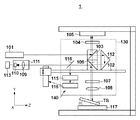
計測装置1は、主な構成として、光源101と、ステージ102と、基準ミラー105と、検出部111と、干渉光学系130と、オートフォーカス系140とを有する。干渉光学系130は、平行光を射出する光源101からの光を2つの光に分割し、一方の光を、集光レンズ108を介して計測面TSに入射させ、他方の光を参照面に入射させ、計測面TSで反射された光と参照面で反射された光とを干渉させる光学系である。計測装置1において、干渉光学系130は、非接触型プローブ(光プローブ)として機能する。   The measurement apparatus 1 includes a light source 101, a stage 102, a reference mirror 105, a detection unit 111, an interference optical system 130, and an autofocus system 140 as main components. The interference optical system 130 divides the light from the light source 101 that emits parallel light into two lights, makes one light incident on the measurement surface TS via the condenser lens 108, and makes the other light the reference surface. It is an optical system that causes the light reflected by the measurement surface TS and the light reflected by the reference surface to interfere with each other. In the measurement apparatus 1, the interference optical system 130 functions as a non-contact type probe (optical probe).

光源101から射出された光は、ステージ102に保持された干渉光学系130の偏光ビームスプリッタ103に入射する。なお、光源101から射出された光は、図1では、Y軸又はZ軸に平行であるように図示されているが、実際には、若干の傾き誤差を含んでいる。   The light emitted from the light source 101 is incident on the polarization beam splitter 103 of the interference optical system 130 held on the stage 102. Note that the light emitted from the light source 101 is shown in FIG. 1 as being parallel to the Y axis or the Z axis, but actually includes a slight tilt error.

ステージ102は、図2に示すように、X軸駆動部151及びY軸駆動部152によって、XY平面内で駆動される。また、ステージ102は、Y軸駆動部152及びZ軸駆動部153によって、YZ平面内で駆動される。X軸駆動部151、Y軸駆動部152及びZ軸駆動部153は、干渉光学系130(を保持するステージ102)を位置決めする位置決め機構として機能する。   As shown in FIG. 2, the stage 102 is driven in the XY plane by an X-axis drive unit 151 and a Y-axis drive unit 152. The stage 102 is driven in the YZ plane by the Y-axis drive unit 152 and the Z-axis drive unit 153. The X-axis drive unit 151, the Y-axis drive unit 152, and the Z-axis drive unit 153 function as a positioning mechanism that positions the interference optical system 130 (the stage 102 that holds the interference optical system 130).

光源101と偏光ビームスプリッタ103との間には、光ファイバやミラーなどが配置されていてもよい。光源101は、波長及び偏光方向が互いに異なる2つの光、本実施形態では、偏光方向が互いに直交するS偏光の光とP偏光の光とを射出する。偏光ビームスプリッタ103は、S偏光の光を反射し、P偏光の光を透過するように構成されている。従って、光源101からの光のうち、S偏光の光は偏光ビームスプリッタ103で反射されてZ軸と略平行な光となり、λ/4板104に入射する。また、光源101からの光のうち、P偏光の光は偏光ビームスプリッタ103を透過してY軸と略平行な光となり、参照面としてのコーナーキューブ112に入射する。   An optical fiber, a mirror, or the like may be disposed between the light source 101 and the polarizing beam splitter 103. The light source 101 emits two lights having different wavelengths and polarization directions, in this embodiment, S-polarized light and P-polarized light whose polarization directions are orthogonal to each other. The polarization beam splitter 103 is configured to reflect S-polarized light and transmit P-polarized light. Accordingly, of the light from the light source 101, the S-polarized light is reflected by the polarization beam splitter 103, becomes light substantially parallel to the Z axis, and enters the λ / 4 plate 104. Of the light from the light source 101, the P-polarized light is transmitted through the polarization beam splitter 103 to become light substantially parallel to the Y axis, and enters the corner cube 112 as a reference surface.

λ/4板104に入射した光は、λ/4板104を透過して円偏光の光となり、基準ミラー(基準面)105で反射される。基準ミラー105で反射された光は、λ/4板104を再び透過してP偏光の光となり、偏光ビームスプリッタ103を透過して偏光ビームスプリッタ106に入射する。偏光ビームスプリッタ106に入射した光は、偏光ビームスプリッタ106を透過し、λ/4板107を透過して円偏光の光となり、集光レンズ108を介して、計測ステージ117に保持された計測面TSの上に集光される(計測面TSの上に焦点を結ぶ)。計測面TSで反射された光は、集光レンズ108を透過して平行光となり、λ/4板107に入射する。以下では、計測面TSで反射された光を計測光と称する。λ/4板107に入射した計測光は、λ/4板107を透過してS偏光の光となり、偏光ビームスプリッタ106で反射され、レンズ109及びフォトダイオード110を含んで構成された検出部111に入射する。   The light that has entered the λ / 4 plate 104 passes through the λ / 4 plate 104 and becomes circularly polarized light, and is reflected by the reference mirror (reference surface) 105. The light reflected by the reference mirror 105 passes through the λ / 4 plate 104 again to become P-polarized light, passes through the polarizing beam splitter 103, and enters the polarizing beam splitter 106. The light incident on the polarization beam splitter 106 passes through the polarization beam splitter 106, passes through the λ / 4 plate 107, becomes circularly polarized light, and is measured by the measurement surface 117 held by the measurement stage 117 via the condenser lens 108. The light is condensed on the TS (focused on the measurement surface TS). The light reflected by the measurement surface TS passes through the condenser lens 108 to become parallel light and enters the λ / 4 plate 107. Hereinafter, the light reflected by the measurement surface TS is referred to as measurement light. The measurement light incident on the λ / 4 plate 107 passes through the λ / 4 plate 107 to become S-polarized light, is reflected by the polarization beam splitter 106, and includes a lens 109 and a photodiode 110. Is incident on.

一方、コーナーキューブ112に入射した光は、コーナーキューブ112で入射した方向に反射され、偏光ビームスプリッタ106に入射する。以下では、コーナーキューブ112で反射された光を参照光と称する。偏光ビームスプリッタ106に入射した参照光は、偏光ビームスプリッタ106を透過し、偏光ビームスプリッタ106で反射された計測光とともに、検出部111に入射する。検出部111では、計測光と参照光との干渉光が検出され、かかる干渉光に対応する干渉信号、本実施形態では、ヘテロダイン干渉信号が取得される。処理部113は、検出部111で検出された干渉信号に基づいて、計測光の光路長の変化を求める。   On the other hand, the light incident on the corner cube 112 is reflected in the direction incident on the corner cube 112 and enters the polarizing beam splitter 106. Hereinafter, the light reflected by the corner cube 112 is referred to as reference light. The reference light that has entered the polarization beam splitter 106 passes through the polarization beam splitter 106 and enters the detection unit 111 together with the measurement light reflected by the polarization beam splitter 106. The detection unit 111 detects interference light between the measurement light and the reference light, and acquires an interference signal corresponding to the interference light, in this embodiment, a heterodyne interference signal. The processing unit 113 obtains a change in the optical path length of the measurement light based on the interference signal detected by the detection unit 111.

また、計測装置1では、X軸駆動部151及びY軸駆動部152によってステージ102をXY平面内で駆動させながら、検出部111でヘテロダイン干渉信号を取得する。そして、検出部111で取得されるヘテロダイン干渉信号に基づいて計測光の光路長の変化を求めることで、計測面TSの形状を計測することができる。なお、ヘテロダイン干渉信号には、既に説明した計測光の光路からわかるように、基準ミラー(基準面)105の面形状が反映されている。そこで、基準ミラー(基準面)105の面形状は、面形状計測器(例えば、干渉方式計測器)により数nm以下の計測精度で事前に計測されているのが好ましい。その場合、検出部111で取得されたヘテロダイン干渉信号から基準ミラー105の面形状の成分を取り除くことができるため、より正確に計測面TSの形状を計測することができる。   In the measuring apparatus 1, the heterodyne interference signal is acquired by the detection unit 111 while the stage 102 is driven in the XY plane by the X-axis drive unit 151 and the Y-axis drive unit 152. The shape of the measurement surface TS can be measured by obtaining a change in the optical path length of the measurement light based on the heterodyne interference signal acquired by the detection unit 111. The heterodyne interference signal reflects the surface shape of the reference mirror (reference surface) 105, as can be seen from the optical path of the measurement light already described. Therefore, the surface shape of the reference mirror (reference surface) 105 is preferably measured in advance by a surface shape measuring instrument (for example, an interference measuring instrument) with a measurement accuracy of several nanometers or less. In this case, since the surface shape component of the reference mirror 105 can be removed from the heterodyne interference signal acquired by the detection unit 111, the shape of the measurement surface TS can be measured more accurately.

計測装置1において、集光レンズ108は、オートフォーカス系(調整部)140によって、集光レンズ108の光軸に沿った方向における位置が制御されている。具体的には、オートフォーカス系140は、集光レンズ108の焦点深度の範囲内に計測面TSの上の計測箇所が収まる(位置する)ように、集光レンズ108と計測面TSとの間の距離を調整(制御)する。   In the measuring apparatus 1, the position of the condenser lens 108 in the direction along the optical axis of the condenser lens 108 is controlled by an autofocus system (adjusting unit) 140. Specifically, the autofocus system 140 is arranged between the condensing lens 108 and the measurement surface TS so that the measurement location on the measurement surface TS is within the range of the focal depth of the condensing lens 108 (positioned). Adjust (control) the distance.

オートフォーカス系140は、例えば、レンズ駆動部114と、計測部115と、フォーカス制御部116とを含む。レンズ駆動部114は、例えば、ボイスコイルなどで構成され、集光レンズ108を集光レンズ108の光軸に沿った方向に移動させる。計測部115は、集光レンズ108の光軸に沿った方向における位置(集光レンズ108によって集光される光のフォーカス状態)を計測する。フォーカス制御部116は、計測部115の計測結果(フォーカス状態)に基づいて、集光レンズ108の焦点深度の範囲内に計測面TSの上の計測箇所が収まるように、レンズ駆動部114による集光レンズ108の移動を制御する。   The autofocus system 140 includes, for example, a lens driving unit 114, a measurement unit 115, and a focus control unit 116. The lens driving unit 114 is configured by, for example, a voice coil, and moves the condenser lens 108 in a direction along the optical axis of the condenser lens 108. The measurement unit 115 measures the position in the direction along the optical axis of the condenser lens 108 (the focus state of the light condensed by the condenser lens 108). Based on the measurement result (focus state) of the measurement unit 115, the focus control unit 116 collects the light by the lens driving unit 114 so that the measurement location on the measurement surface TS is within the focal depth range of the condensing lens 108. The movement of the optical lens 108 is controlled.

計測部115の構成の一例について説明する。集光レンズ108によって集光される光が集光レンズ108の焦点深度の範囲外となると、計測面TSで反射されて集光レンズ108を再度通過した光は平行光ではなく、収束又は発散する。従って、図10を参照して後述するように、シリンドリカルレンズと4分割センサとで計測部115を構成し、計測面TSで反射された光を、ハーフミラー118を介して計測部115に入射させることによって、フォーカス状態を計測することができる。但し、計測部115の構成は、計測面TSで反射されて集光レンズ108を再度通過した光の収束や発散を利用する構成に限定されるものではなく、その要旨の範囲内で、集光レンズ108を通過した光を利用しない構成であってもよい。   An example of the configuration of the measurement unit 115 will be described. When the light collected by the condenser lens 108 falls outside the range of the focal depth of the condenser lens 108, the light reflected by the measurement surface TS and passing through the condenser lens 108 again is not parallel light but converges or diverges. . Accordingly, as will be described later with reference to FIG. 10, the cylindrical lens and the four-divided sensor constitute the measurement unit 115 and the light reflected by the measurement surface TS is incident on the measurement unit 115 via the half mirror 118. Thus, the focus state can be measured. However, the configuration of the measurement unit 115 is not limited to the configuration using the convergence or divergence of the light reflected by the measurement surface TS and again passing through the condensing lens 108. A configuration in which light that has passed through the lens 108 is not used may be used.

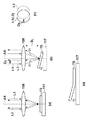
図10(a)乃至図10(c)を参照して、計測部115の詳細な構成の一例を説明する。計測面TSで反射され、集光レンズ108に再度入射して、偏光ビームスプリッタ106を含む光学系に戻る光を利用して、フォーカス状態を計測する方法は、例えば、文献1に紹介されている方法を適用可能である。なお、文献1とは、「メカノプティクス 昭和56年度調査報告(光学工業技術協会)」である。文献1には、非点収差法、ナイフエッジ法、フーコー法、臨界角法などの幾つかの方法が紹介されているが、ここでは、非点収差法を例に説明する。   An example of a detailed configuration of the measurement unit 115 will be described with reference to FIGS. 10 (a) to 10 (c). A method for measuring the focus state using light reflected by the measurement surface TS, reentering the condenser lens 108, and returning to the optical system including the polarization beam splitter 106 is introduced in, for example, Document 1. The method is applicable. Reference 1 is “Mechanoptics 1986 Survey Report (Optical Industry and Technology Association)”. Reference 1 introduces several methods such as the astigmatism method, the knife edge method, the Foucault method, and the critical angle method. Here, the astigmatism method will be described as an example.

図10(a)乃至図10(c)は、非点収差法を用いた計測部115の構成を示す概略図である。図10(a)に示すように、集光レンズ108の焦点近傍の位置をB、位置Bを基準として集光レンズ108から離れた位置をA、位置Bを基準として集光レンズ108に近づいた位置をCとする。計測面TSで反射された光LLは、位置Aで反射されると収束光、位置Bで反射されると平行光、位置Cで反射されると発散光となる。   FIG. 10A to FIG. 10C are schematic views showing the configuration of the measurement unit 115 using the astigmatism method. As shown in FIG. 10A, the position near the focal point of the condensing lens 108 is B, the position distant from the condensing lens 108 is based on the position B, and the position is close to the condensing lens 108 based on the position B. Let C be the position. The light LL reflected by the measurement surface TS becomes convergent light when reflected at the position A, parallel light when reflected at the position B, and divergent light when reflected at the position C.

計測部115は、図10(b)に示すように、コリメータレンズ1002、シリンドリカルレンズ1003及び4分割センサ1006で構成される。シリンドリカルレンズ1003の光学的に屈折力を持つ面内を通過する光LL1と、シリンドリカルレンズ1003の光学的に屈折力を持たない面内を通過する光LL2とが集光され、4分割センサ1006の上で円形状又は楕円形状の光強度分布を形成する。図10(b)には、シリンドリカルレンズ1003の光学的に屈折力を持たない面内(紙面に垂直な面内)を通過する光LL2の集光状態を点線で示した。4分割センサ1006の上で形成される光強度分布を詳細に説明すると、次のようになる。例えば、図10(c)に示すように、位置Aで反射された収束光は、4分割センサ1006の上で横長の光強度分布LD1を形成し、位置Bで反射された平行光は、4分割センサ1006の上で円形の光強度分布LD2を形成する。また、位置Cで反射された発散光は、4分割センサ1006の上で縦長の光強度分布LD3を形成する。従って、演算処理デバイスOPにおいて、4分割センサ1006を構成する4つの光センサS1、S2、S3及びS4のそれぞれが検知する光出力P1、P2、P3及びP4に基づいて、集光レンズ108に対する計測面TSの位置を求めることが可能となる。具体的には、P1+P3<P2+P4であれば光LLは位置Aで反射され、P1+P3=P2+P4であれば光LLは位置Bで反射され、P1+P3>P2+P4であれば光LLは位置Cで反射されたと検知することができる。更に、P1+P3の値及びP2+P4の値を、電気的に高精度に検出することによって、計測面TSの位置を位置Bを基準(中心)として高精度に求めることが可能である。   As shown in FIG. 10B, the measurement unit 115 includes a collimator lens 1002, a cylindrical lens 1003, and a quadrant sensor 1006. The light LL1 that passes through the optical surface of the cylindrical lens 1003 that has optical power and the light LL2 that passes through the optical surface of the cylindrical lens 1003 that does not have optical power are collected and collected by the quadrant sensor 1006. A circular or elliptical light intensity distribution is formed above. In FIG. 10B, the condensing state of the light LL2 that passes through the plane of the cylindrical lens 1003 that does not have optical power (in the plane perpendicular to the paper surface) is indicated by a dotted line. The light intensity distribution formed on the quadrant sensor 1006 will be described in detail as follows. For example, as shown in FIG. 10C, the convergent light reflected at the position A forms a horizontally long light intensity distribution LD1 on the four-divided sensor 1006, and the parallel light reflected at the position B is 4 A circular light intensity distribution LD2 is formed on the split sensor 1006. Further, the divergent light reflected at the position C forms a vertically long light intensity distribution LD3 on the quadrant sensor 1006. Accordingly, in the arithmetic processing device OP, the measurement with respect to the condensing lens 108 is performed based on the light outputs P1, P2, P3, and P4 detected by each of the four optical sensors S1, S2, S3, and S4 constituting the quadrant sensor 1006. The position of the surface TS can be obtained. Specifically, if P1 + P3 <P2 + P4, the light LL is reflected at the position A, if P1 + P3 = P2 + P4, the light LL is reflected at the position B, and if P1 + P3> P2 + P4, the light LL is reflected at the position C. Can be detected. Furthermore, by detecting the values of P1 + P3 and P2 + P4 electrically with high accuracy, the position of the measurement surface TS can be obtained with high accuracy using the position B as a reference (center).

このように、計測部115は、計測面TSで反射され、集光レンズ108に再度入射して、偏光ビームスプリッタ106を含む光学系に戻る光を利用して、フォーカス状態を計測することができる。   As described above, the measurement unit 115 can measure the focus state by using the light reflected by the measurement surface TS, reentering the condenser lens 108, and returning to the optical system including the polarization beam splitter 106. .

上述したように、集光レンズ108によって集光される光が集光レンズ108の焦点深度の範囲外になると、計測面TSで反射されて集光レンズ108を再度通過した光は、収束又は発散する。更に、集光レンズ108の焦点深度の範囲内であっても、光LLが微小に収束又は発散するような計測面TSの位置も存在する。従って、コリメータレンズ1002、シリンドリカルレンズ1003及び4分割センサ1006で計測部115を構成し、計測面TSで反射された光を、ハーフミラー118を介して計測部115に入射させることで、フォーカス状態を計測することができる。ここで、ハーフミラー118は、ハーフミラー118を透過する光(透過光)とハーフミラー118で反射される光(反射光)とを適当な割合で分割する光学部品であって、透過光と反射光とをそれぞれ50%に分割する光学部品に限定されるものではない。   As described above, when the light collected by the condensing lens 108 is out of the range of the focal depth of the condensing lens 108, the light reflected by the measurement surface TS and again passing through the condensing lens 108 converges or diverges. To do. Further, even within the range of the focal depth of the condenser lens 108, there is a position on the measurement surface TS where the light LL converges or diverges slightly. Accordingly, the collimator lens 1002, the cylindrical lens 1003, and the quadrant sensor 1006 constitute the measurement unit 115, and the light reflected by the measurement surface TS is incident on the measurement unit 115 via the half mirror 118, so that the focus state is changed. It can be measured. Here, the half mirror 118 is an optical component that divides light transmitted through the half mirror 118 (transmitted light) and light reflected by the half mirror 118 (reflected light) at an appropriate ratio. It is not limited to optical components that divide light into 50% each.

また、オートフォーカス系140は、図3に示すように、レンズ駆動部114ではなく、干渉光学系130を保持するステージ102及びZ軸駆動部153を用いて、集光レンズ108の光軸に沿った方向における集光レンズ108の位置を制御してもよい。この場合、フォーカス制御部116は、計測部115の計測結果(フォーカス状態)に基づいて、集光レンズ108の焦点深度の範囲内に計測面TSの上の計測箇所が収まるように、Z軸駆動部153によるステージ102の移動を制御する。Z軸駆動部153は、上述したように、ステージ102をZ軸方向に駆動する駆動部であるため、ステージ102によって保持される干渉光学系130の集光レンズ108を集光レンズ108の光軸に沿った方向に移動させることができる。   Further, as shown in FIG. 3, the autofocus system 140 uses the stage 102 holding the interference optical system 130 and the Z-axis drive unit 153 instead of the lens drive unit 114, and follows the optical axis of the condenser lens 108. The position of the condenser lens 108 in the selected direction may be controlled. In this case, the focus control unit 116 performs Z-axis driving so that the measurement location on the measurement surface TS is within the focal depth range of the condenser lens 108 based on the measurement result (focus state) of the measurement unit 115. The movement of the stage 102 by the unit 153 is controlled. Since the Z-axis driving unit 153 is a driving unit that drives the stage 102 in the Z-axis direction as described above, the condensing lens 108 of the interference optical system 130 held by the stage 102 is used as the optical axis of the condensing lens 108. It can be moved in the direction along.

ここで、図4を参照して、計測ステージ117に保持された計測面TSに入射する光及び計測面TSで反射された光(計測光)について説明する。図4(a)は、集光レンズ108の光軸AXに対して計測面TSが傾いていない状態において、集光レンズ108を介して計測面TSに入射する光L1、及び、計測面TSで反射されて集光レンズ108に入射する光L2を示している。   Here, with reference to FIG. 4, the light which injects into the measurement surface TS hold | maintained at the measurement stage 117, and the light (measurement light) reflected by the measurement surface TS are demonstrated. FIG. 4A illustrates the light L1 incident on the measurement surface TS via the condensing lens 108 and the measurement surface TS in a state where the measurement surface TS is not inclined with respect to the optical axis AX of the condensing lens 108. The light L2 reflected and incident on the condenser lens 108 is shown.

一方、図4(b)に示すように、集光レンズ108の光軸AXに対して計測面TSが角度θだけ傾いた状態では、集光レンズ108に平行光で入射した光L1は、計測面TSにおいて角度2θで反射され、集光レンズ108に入射(再入射)する。この際、計測面TSに入射する光L1は、オートフォーカス系140によって、集光レンズ108の焦点深度の範囲内に計測面TSの上の計測箇所が収まるように制御されている。従って、集光レンズ108に再入射した光L3は、集光レンズ108を通過して平行光となる。但し、計測面TSが光軸AXに対して角度θだけ傾いているため、図4(c)に示すように、光L3の光軸中心は、光L1(光L2)の光軸中心からシフトしている。光L1の光軸中心からの光L3の光軸中心のシフト量Dは、集光レンズ108と計測面TSとの間の距離Dと角度2θとにほぼ比例した量となる。 On the other hand, as shown in FIG. 4B, in a state where the measurement surface TS is inclined by the angle θ with respect to the optical axis AX of the condenser lens 108, the light L1 incident on the condenser lens 108 as parallel light is measured. The light is reflected at an angle 2θ on the surface TS and enters (re-enters) the condenser lens 108. At this time, the light L1 incident on the measurement surface TS is controlled by the autofocus system 140 so that the measurement location on the measurement surface TS is within the focal depth range of the condenser lens 108. Therefore, the light L3 re-entering the condenser lens 108 passes through the condenser lens 108 and becomes parallel light. However, since the measurement surface TS is inclined by an angle θ with respect to the optical axis AX, as shown in FIG. 4C, the optical axis center of the light L3 is shifted from the optical axis center of the light L1 (light L2). doing. Shift amount D s of the center of the optical axis of the light L3 from the optical axis of the light L1 is substantially proportional amounts to the distance D L and the angle 2θ between the condenser lens 108 and the measurement surface TS.

集光レンズ108の光軸AXに対して角度θだけ傾いた計測面TSで反射された光(計測光)L3とコーナーキューブ112で反射された光(参照光)とは、重なり合いながら検出部111に入射し、ヘテロダイン干渉信号として検出部111で取得される。この際、集光レンズ108の光軸AXに対して計測面TSが角度θだけ傾いていることによって、計測光の光軸中心が参照光の光軸中心からシフトしている(シフト量D)ため、その分だけヘテロダイン干渉信号の強度が低下している。但し、ヘテロダイン干渉方式における位相計測に要求される精度には影響しない程度であり、面形状を高精度に求めることができる。 The light (measurement light) L3 reflected by the measurement surface TS inclined by the angle θ with respect to the optical axis AX of the condensing lens 108 and the light (reference light) reflected by the corner cube 112 are overlapped with each other, and the detection unit 111 is overlapped. And is acquired by the detection unit 111 as a heterodyne interference signal. At this time, since the measurement surface TS is inclined by the angle θ with respect to the optical axis AX of the condenser lens 108, the optical axis center of the measurement light is shifted from the optical axis center of the reference light (shift amount D s Therefore, the intensity of the heterodyne interference signal is reduced accordingly. However, it does not affect the accuracy required for phase measurement in the heterodyne interference method, and the surface shape can be obtained with high accuracy.

また、本実施形態では、集光レンズ108の光軸AXに対して計測面TSが角度θだけ傾いた状態について説明した。但し、図4(d)に示すように、計測面TSが各位置で異なる角度を有する場合や計測面TSが非球面形状を有する場合にも、同様に、面形状を高精度に求めることができる。   In the present embodiment, the state in which the measurement surface TS is inclined by the angle θ with respect to the optical axis AX of the condenser lens 108 has been described. However, as shown in FIG. 4D, when the measurement surface TS has a different angle at each position or when the measurement surface TS has an aspherical shape, the surface shape can be obtained with high accuracy in the same manner. it can.

図5(a)乃至図5(c)を参照して、集光レンズ108の焦点深度の範囲内に計測面TSの上の計測箇所が収まるように制御することの必要性について説明する。図5(a)は、集光レンズ108の焦点位置が計測面TSのZ軸方向(光軸方向)における位置Pに一致している状態を示している。図5(a)において、集光レンズ108の焦点深度の範囲RDFとして、集光レンズ108の焦点深度の上限値RUP及び下限値RLOを定義している。集光レンズ108の主平面のZ軸方向(光軸方向)における位置をPとする。 With reference to FIG. 5A to FIG. 5C, the necessity of controlling the measurement location on the measurement surface TS within the focal depth range of the condenser lens 108 will be described. FIG. 5A shows a state in which the focal position of the condensing lens 108 matches the position PT in the Z-axis direction (optical axis direction) of the measurement surface TS. In FIG. 5A, an upper limit value R UP and a lower limit value R LO of the focal depth of the condenser lens 108 are defined as the focal depth range R DF of the condenser lens 108. The position in the main plane of the Z-axis direction (optical axis direction) of the condenser lens 108 and P M.

図5(b)及び図5(c)に示すように、計測面TSの位置Pに対して、集光レンズ108が焦点深度の範囲RDF(焦点深度の上限値RUPと下限値RLOとの間)で光軸方向に集光点がシフトした場合を考える。この場合、計測面TSで反射された光L4の波面の波面収差は十分に小さいため、ヘテロダイン干渉方式では、計測面TSの移動量を数nm以下の高精度で計測することができる。 As shown in FIGS. 5B and 5C, the condensing lens 108 moves the focal depth range R DF (the upper limit value R UP and the lower limit value R of the focal depth) with respect to the position PT on the measurement surface TS. Let us consider a case where the focal point is shifted in the direction of the optical axis (between LO ). In this case, since the wavefront aberration of the wavefront of the light L4 reflected by the measurement surface TS is sufficiently small, the amount of movement of the measurement surface TS can be measured with high accuracy of several nm or less in the heterodyne interference method.

このように、計測装置1は、集光レンズ108の焦点深度の範囲内に計測面TSの上の計測箇所が収まるように、集光レンズ108の光軸方向における位置を制御している。これにより、計測面TSで反射されて集光レンズ108に入射した光(計測光)は、平行光として偏光ビームスプリッタ106で反射され、コーナーキューブ112で反射された光(参照光)とともに検出部111で検出される。従って、検出部111において良好なヘテロダイン信号が検出される。このため、計測装置1は、干渉光学系130を保持するステージ102をXY平面内で移動させながら、検出部111でヘテロダイン干渉信号を取得することで、計測面TSの形状を高精度に計測することができる。特に、計測装置1は、曲率を有する計測面の形状を、その広範囲にわたって、数mmのピッチで高精度に計測することができるため、セグメントミラーの表面形状の計測に有利である。   As described above, the measurement apparatus 1 controls the position of the condenser lens 108 in the optical axis direction so that the measurement location on the measurement surface TS is within the range of the focal depth of the condenser lens 108. Thereby, the light (measurement light) reflected by the measurement surface TS and incident on the condenser lens 108 is reflected by the polarization beam splitter 106 as parallel light and together with the light (reference light) reflected by the corner cube 112, the detection unit. 111. Therefore, a good heterodyne signal is detected by the detection unit 111. For this reason, the measuring apparatus 1 measures the shape of the measurement surface TS with high accuracy by acquiring the heterodyne interference signal by the detection unit 111 while moving the stage 102 holding the interference optical system 130 in the XY plane. be able to. In particular, the measuring device 1 is advantageous in measuring the surface shape of the segment mirror because the shape of the measuring surface having a curvature can be measured with high accuracy over a wide range at a pitch of several millimeters.

本実施形態では、干渉光学系130として、ヘテロダイン干渉方式を利用した非接触型プローブを用いる場合について説明したが、ホモダイン干渉方式を利用した非接触型プローブを用いてもよい。また、本実施形態の構成は、ステージ102をXY平面内で移動させながら検出部111で干渉信号を取得して計測光の光路長の変化を求めるものであるから、表面形状に限らず当該変化に相関のある物体の特性を計測することができる。例えば、物体の表面粗さを計測することもできる。   In this embodiment, the case where a non-contact type probe using a heterodyne interference method is used as the interference optical system 130 has been described, but a non-contact type probe using a homodyne interference method may be used. In the configuration of the present embodiment, the stage 102 is moved in the XY plane, the interference signal is acquired by the detection unit 111, and the change in the optical path length of the measurement light is obtained. It is possible to measure the characteristics of an object having a correlation with. For example, the surface roughness of the object can be measured.

また、図10を参照してフォーカス状態を検知する方法の一例を説明したが、フォーカス状態を検知するために他の方法を用いてもよい。例えば、検出部111を構成するレンズ109とフォトダイオード110との間に光ファイバー(不図示)を配置した構成においても、フォーカス状態を検知することができる。計測面TSが集光レンズ108の焦点深度の範囲内にある場合、計測面TSで反射した後、レンズ109に入射する干渉光は平行光になる。そのため、光ファイバー(不図示)の入射端面をレンズ109の焦点位置に配置しておけば、干渉光は、レンズ109により光ファイバー(不図示)の入射端面上に良好に集光される。その結果、入射端面上に集光された干渉光は、光ファイバー(不図示)に良好に結合される(効率よく導入される)。一方、計測面TSが集光レンズ108の焦点深度の範囲外にある場合には、干渉光の光ファイバー(不図示)への結合効率は低下する。これは、計測面TSで反射されて集光レンズ108を再度通過した光が平行光ではなく、収束光又は発散光となるため、レンズ109を透過した後、光ファイバー(不図示)の入射端面上に良好に集光されないためである。その結果、干渉光の光ファイバー(不図示)への結合の効率が劣化する。この現象を利用して、光ファイバー(不図示)の射出端面からフォトダイオード110に入射する光量をフォトダイオード110の出力でモニターすることにより、フォーカス状態を検知することができる。   In addition, although an example of the method for detecting the focus state has been described with reference to FIG. 10, other methods may be used for detecting the focus state. For example, even in a configuration in which an optical fiber (not shown) is arranged between the lens 109 and the photodiode 110 that constitute the detection unit 111, the focus state can be detected. When the measurement surface TS is within the range of the focal depth of the condensing lens 108, the interference light incident on the lens 109 after being reflected by the measurement surface TS becomes parallel light. Therefore, if the incident end face of the optical fiber (not shown) is arranged at the focal position of the lens 109, the interference light is well condensed on the incident end face of the optical fiber (not shown) by the lens 109. As a result, the interference light collected on the incident end face is well coupled (efficiently introduced) to an optical fiber (not shown). On the other hand, when the measurement surface TS is outside the range of the focal depth of the condensing lens 108, the coupling efficiency of the interference light to the optical fiber (not shown) decreases. This is because the light reflected by the measurement surface TS and passing through the condenser lens 108 again is not parallel light, but convergent light or divergent light, and thus after passing through the lens 109, on the incident end face of an optical fiber (not shown). This is because the light is not collected well. As a result, the efficiency of coupling interference light to an optical fiber (not shown) is degraded. By utilizing this phenomenon, the focus state can be detected by monitoring the amount of light incident on the photodiode 110 from the exit end face of the optical fiber (not shown) by the output of the photodiode 110.

<第2の実施形態>
図6は、本発明の第2の実施形態における計測装置1Aの構成を示す概略図である。計測装置1Aは、計測面で反射された計測光と参照面で反射された参照光とを干渉させ、計測光の光路長の変化を計測する機能を有し、本実施形態では、ヘテロダイン干渉方式を利用した非接触型プローブを備えた3次元形状計測装置として具現化される。計測装置1Aは、例えば、曲率を有し、外周円の直径が1mを超すような計測面の形状(例えば、望遠鏡の主鏡として使用可能な複合ミラーを構成するセグメントミラーの表面形状)の計測に好適である。
<Second Embodiment>
FIG. 6 is a schematic diagram showing the configuration of a measuring apparatus 1A according to the second embodiment of the present invention. The measurement apparatus 1A has a function of causing the measurement light reflected by the measurement surface to interfere with the reference light reflected by the reference surface, and measuring a change in the optical path length of the measurement light. In this embodiment, the heterodyne interference method It is embodied as a three-dimensional shape measuring apparatus provided with a non-contact type probe using the. The measurement apparatus 1A measures, for example, the shape of a measurement surface having a curvature and a diameter of the outer circumference circle exceeding 1 m (for example, the surface shape of a segment mirror constituting a composite mirror that can be used as a primary mirror of a telescope). It is suitable for.

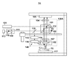
計測装置1Aは、主な構成として、光源101と、ステージ102と、基準ミラー105と、検出部111と、干渉光学系130Aと、オートフォーカス系140とを有する。干渉光学系130Aは、本実施形態では、光源101からの光が計測面TSと基準ミラー105との間を2回往復するダブルパスのヘテロダイン干渉系を構成する。また、計測装置1Aにおいて、干渉光学系130Aは、非接触型プローブ(光プローブ)として機能する。   The measurement apparatus 1A includes a light source 101, a stage 102, a reference mirror 105, a detection unit 111, an interference optical system 130A, and an autofocus system 140 as main components. In the present embodiment, the interference optical system 130A constitutes a double-pass heterodyne interference system in which light from the light source 101 reciprocates twice between the measurement surface TS and the reference mirror 105. In the measurement apparatus 1A, the interference optical system 130A functions as a non-contact type probe (optical probe).

光源101から射出された光(平行光)は、ステージ102に保持された干渉光学系130Aの偏光ビームスプリッタ181に入射する。光源101は、波長及び偏光方向が互いに異なる2つの光、本実施形態では、偏光方向が互いに直交するS偏光の光とP偏光の光とを射出する。偏光ビームスプリッタ181は、S偏光の光を反射し、P偏光の光を透過するように構成されている。従って、光源101からの光のうち、S偏光の光は偏光ビームスプリッタ181で反射されてZ軸と略平行な光となり、λ/4板104に入射する。また、光源101からの光のうち、P偏光の光は偏光ビームスプリッタ181を透過してY軸と略平行な光となり、参照面としてのコーナーキューブ112に入射する。   The light (parallel light) emitted from the light source 101 enters the polarization beam splitter 181 of the interference optical system 130 </ b> A held on the stage 102. The light source 101 emits two lights having different wavelengths and polarization directions, in this embodiment, S-polarized light and P-polarized light whose polarization directions are orthogonal to each other. The polarization beam splitter 181 is configured to reflect S-polarized light and transmit P-polarized light. Accordingly, among the light from the light source 101, S-polarized light is reflected by the polarization beam splitter 181 to become light substantially parallel to the Z axis and enters the λ / 4 plate 104. Of the light from the light source 101, P-polarized light is transmitted through the polarization beam splitter 181 and becomes substantially parallel to the Y axis, and is incident on the corner cube 112 as a reference surface.

λ/4板104に入射した光は、λ/4板104を透過して円偏光の光となり、基準ミラー(基準面)105で反射される。基準ミラー105で反射された光は、λ/4板104を再び透過してP偏光の光となり、偏光ビームスプリッタ181を透過してλ/4板107に入射する。λ/4板107に入射した光は、λ/4板107を透過して円偏光の光となり、集光レンズ182を介して、計測ステージ117に保持された計測面TSの上に集光される(計測面TSの上に焦点を結ぶ)。計測面TSで反射された光は、集光レンズ182を透過して平行光となり、λ/4板107に入射する。λ/4板107に入射した光は、λ/4板107を透過してS偏光の光となり、偏光ビームスプリッタ181で反射され、コーナーキューブ112に入射する。コーナーキューブ112で反射された光は、偏光ビームスプリッタ181で反射され、λ/4板107及び集光レンズ182を介して、再度、計測面TSの上に集光される。この際、計測面TSで反射された光は、集光レンズ182を透過して平行光となり、λ/4板107に入射する。以下では、計測面TSで2回反射された光を計測光と称する。λ/4板107に入射した計測光は、λ/4板107を透過してP偏光の光となり、偏光ビームスプリッタ181を透過してλ/4板104に入射する。λ/4板104に入射した光は、λ/4板104を透過して円偏光の光となり、基準ミラー(基準面)105で反射される。基準ミラー105で反射された光は、λ/4板104を再び透過してS偏光の光となり、偏光ビームスプリッタ181で反射され、レンズ109及びフォトダイオード110で構成された検出部111に入射する。   The light that has entered the λ / 4 plate 104 passes through the λ / 4 plate 104 and becomes circularly polarized light, and is reflected by the reference mirror (reference surface) 105. The light reflected by the reference mirror 105 passes through the λ / 4 plate 104 again to become P-polarized light, passes through the polarization beam splitter 181, and enters the λ / 4 plate 107. The light incident on the λ / 4 plate 107 passes through the λ / 4 plate 107 and becomes circularly polarized light, and is condensed on the measurement surface TS held on the measurement stage 117 via the condenser lens 182. (Focus on the measurement surface TS). The light reflected by the measurement surface TS passes through the condenser lens 182 and becomes parallel light and enters the λ / 4 plate 107. The light incident on the λ / 4 plate 107 passes through the λ / 4 plate 107 to become S-polarized light, is reflected by the polarization beam splitter 181, and enters the corner cube 112. The light reflected by the corner cube 112 is reflected by the polarization beam splitter 181, and is condensed again on the measurement surface TS through the λ / 4 plate 107 and the condenser lens 182. At this time, the light reflected by the measurement surface TS passes through the condenser lens 182 to become parallel light and enters the λ / 4 plate 107. Hereinafter, the light reflected twice by the measurement surface TS is referred to as measurement light. The measurement light incident on the λ / 4 plate 107 passes through the λ / 4 plate 107 to become P-polarized light, passes through the polarization beam splitter 181, and enters the λ / 4 plate 104. The light that has entered the λ / 4 plate 104 passes through the λ / 4 plate 104 and becomes circularly polarized light, and is reflected by the reference mirror (reference surface) 105. The light reflected by the reference mirror 105 passes through the λ / 4 plate 104 again to become S-polarized light, is reflected by the polarization beam splitter 181, and enters the detection unit 111 including the lens 109 and the photodiode 110. .

一方、コーナーキューブ112に入射した光は、コーナーキューブ112で入射した方向に反射され、偏光ビームスプリッタ181に入射する。以下では、計測面TSで反射されることなく、コーナーキューブ112で反射された光を参照光と称する。偏光ビームスプリッタ181に入射した参照光は、偏光ビームスプリッタ181を透過し、偏光ビームスプリッタ181で反射された計測光とともに、検出部111に入射する。検出部111では、計測光と参照光との干渉光が検出され、かかる干渉光に対応する干渉信号、本実施形態では、ヘテロダイン干渉信号が取得される。処理部113は、検出部111で検出された干渉信号に基づいて、計測光の光路長の変化を求める。   On the other hand, the light incident on the corner cube 112 is reflected in the direction incident on the corner cube 112 and enters the polarization beam splitter 181. Hereinafter, the light reflected by the corner cube 112 without being reflected by the measurement surface TS is referred to as reference light. The reference light incident on the polarization beam splitter 181 passes through the polarization beam splitter 181 and enters the detection unit 111 together with the measurement light reflected by the polarization beam splitter 181. The detection unit 111 detects interference light between the measurement light and the reference light, and acquires an interference signal corresponding to the interference light, in this embodiment, a heterodyne interference signal. The processing unit 113 obtains a change in the optical path length of the measurement light based on the interference signal detected by the detection unit 111.

また、計測装置1Aでは、X軸駆動部151及びY軸駆動部152によってステージ102をXY平面内で移動させながら、検出部111でヘテロダイン干渉信号を取得する。換言すれば、干渉光学系130Aからの光(集光レンズ182によって集光される光)が計測面TSの上の複数の位置に入射するように、干渉光学系130A(を保持するステージ102)を位置決めしながら検出部111でヘテロダイン干渉信号を取得する。そして、検出部111で取得されたヘテロダイン干渉信号に基づいて計測光の光路長の変化を求めることで、計測面TSの形状を計測することができる。   In the measuring apparatus 1A, the detection unit 111 acquires a heterodyne interference signal while the stage 102 is moved in the XY plane by the X-axis drive unit 151 and the Y-axis drive unit 152. In other words, the interference optical system 130A (the stage 102 that holds the interference optical system 130A) so that light from the interference optical system 130A (light condensed by the condensing lens 182) is incident on a plurality of positions on the measurement surface TS. The heterodyne interference signal is acquired by the detection unit 111 while positioning. The shape of the measurement surface TS can be measured by obtaining a change in the optical path length of the measurement light based on the heterodyne interference signal acquired by the detection unit 111.

計測装置1Aでは、計測装置1と同様に、集光レンズ182の焦点深度の範囲内に計測面TSの上の計測箇所が収まる(位置する)ように、集光レンズ182の光軸方向における集光レンズ182の位置が制御されている。これにより、計測面TSで反射されて集光レンズ182に入射した光(計測光)は、平行光として偏光ビームスプリッタ181で反射され、コーナーキューブ112で反射された光(参照光)とともに検出部111で検出される。従って、検出部111において良好なヘテロダイン信号が検出される。このため、干渉光学系130Aをダブルパスのヘテロダイン干渉系で構成した場合にも、計測装置1Aは、計測面TSの形状を高精度に計測することができる。具体的には、計測装置1Aは、干渉光学系130Aを保持するステージ102をXY平面内で移動させながら、検出部111でヘテロダイン干渉信号を取得することで、計測面TSの形状を高精度に計測することができる。   In the measurement device 1A, as in the measurement device 1, the collection point in the optical axis direction of the condensing lens 182 is set so that the measurement location on the measurement surface TS is within the range of the focal depth of the condensing lens 182. The position of the optical lens 182 is controlled. Thereby, the light (measurement light) reflected by the measurement surface TS and incident on the condensing lens 182 is reflected by the polarization beam splitter 181 as parallel light, and is detected together with the light (reference light) reflected by the corner cube 112. 111. Therefore, a good heterodyne signal is detected by the detection unit 111. Therefore, even when the interference optical system 130A is configured by a double-pass heterodyne interference system, the measurement apparatus 1A can measure the shape of the measurement surface TS with high accuracy. Specifically, the measurement apparatus 1A acquires the heterodyne interference signal by the detection unit 111 while moving the stage 102 holding the interference optical system 130A in the XY plane, thereby accurately adjusting the shape of the measurement surface TS. It can be measured.

<第3の実施形態>
図7は、本発明の第3の実施形態における計測装置1Bの構成を示す概略図である。計測装置1Bは、計測面で反射された計測光の光路長の変化を計測する機能を有し、本実施形態では、ヘテロダイン干渉方式を利用した非接触型プローブを備えた3次元形状計測装置として具現化される。
<Third Embodiment>
FIG. 7 is a schematic diagram illustrating the configuration of a measurement apparatus 1B according to the third embodiment of the present invention. The measurement apparatus 1B has a function of measuring a change in the optical path length of the measurement light reflected from the measurement surface. In this embodiment, the measurement apparatus 1B is a three-dimensional shape measurement apparatus including a non-contact type probe using a heterodyne interference method. Embodied.

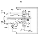
計測装置1Bは、主な構成として、第2光源909と、ステージ102と、基準ミラー105と、干渉光学系(計測用干渉光学系)130Bと、オートフォーカス系140とを有する。干渉光学系130Bは、本実施形態では、第2光源909からの光が計測面TSと偏光ビームスプリッタ905との間を1回往復するシングルパスのヘテロダイン干渉系を構成する。また、計測装置1Bにおいて、干渉光学系130Bは、非接触型プローブ(光プローブ)として機能する。以下に、計測装置1Bの構成の概要を説明する。   The measuring apparatus 1B includes a second light source 909, a stage 102, a reference mirror 105, an interference optical system (measuring interference optical system) 130B, and an autofocus system 140 as main components. In the present embodiment, the interference optical system 130B constitutes a single-pass heterodyne interference system in which light from the second light source 909 reciprocates once between the measurement surface TS and the polarization beam splitter 905. In the measuring apparatus 1B, the interference optical system 130B functions as a non-contact type probe (optical probe). Below, the outline | summary of a structure of the measuring device 1B is demonstrated.

第1光源901から射出された光(平行光)は、基準ミラー105と両面ミラー904とで反射した第1計測光の光路長の変化を求めるために用いられる。第1光源901から射出された光は、偏光ビームスプリッタや偏光ビームスプリッタの上下に配置されたλ/4板、コーナーキューブ902などを通過して検出部903で検出される。ここで、検出部903は、レンズ、フォトダイオード、処理部などから構成され、検出された干渉信号に基づいて、計測光の光路長の変化を求める。このようにして第1計測光の光路長の変化を求めることにより、基準ミラー105に対する、シングルパス光学系である干渉光学系130Bを含む干渉光学系908の上下の動きを、高精度に計測することができる。   The light (parallel light) emitted from the first light source 901 is used to determine the change in the optical path length of the first measurement light reflected by the reference mirror 105 and the double-sided mirror 904. The light emitted from the first light source 901 passes through the polarization beam splitter, the λ / 4 plates disposed above and below the polarization beam splitter, the corner cube 902, and the like, and is detected by the detection unit 903. Here, the detection unit 903 includes a lens, a photodiode, a processing unit, and the like, and obtains a change in the optical path length of the measurement light based on the detected interference signal. By determining the change in the optical path length of the first measurement light in this manner, the vertical movement of the interference optical system 908 including the interference optical system 130B, which is a single-pass optical system, with respect to the reference mirror 105 is measured with high accuracy. be able to.

また、第2光源909から射出された光(平行光)は、両面ミラー904と計測面TSとで反射した第2計測光の光路長の変化を求めるために用いられる。第2光源909から射出された光は、偏光ビームスプリッタ905を透過した後にコーナーキューブを通過する光と、偏光ビームスプリッタ905で反射した後にλ/4板、両面ミラー904、集光レンズ906などを通過する光とに分離される。そして、検出部111で検出された干渉信号に基づいて、計測光の光路長の変化を求める。このようにして第2計測光の光路長の変化を求めることにより、計測面TSの面形状を、干渉光学系908を基準として、高精度に計測することができる。   Further, the light (parallel light) emitted from the second light source 909 is used to obtain a change in the optical path length of the second measurement light reflected by the double-sided mirror 904 and the measurement surface TS. The light emitted from the second light source 909 passes through the corner cube after passing through the polarization beam splitter 905, and after being reflected by the polarization beam splitter 905, passes through a λ / 4 plate, a double-sided mirror 904, a condenser lens 906, and the like. Separated into light passing through. Based on the interference signal detected by the detection unit 111, a change in the optical path length of the measurement light is obtained. By determining the change in the optical path length of the second measurement light in this way, the surface shape of the measurement surface TS can be measured with high accuracy using the interference optical system 908 as a reference.

計測装置1Bは、シングルパス光学系である干渉光学系130Bを含む干渉光学系908を用いて、第1計測光の光路長の変化及び第2計測光の光路長の変化を求める。これにより、シングルパス光学系である干渉光学系130Bを含む干渉光学系908の上下動の影響を低減して、計測装置1や計測装置1Aと同様に、基準ミラー105を基準として、計測面TSの形状を数nm以下の高精度で計測することができる。ここで、計測装置1Bにおける干渉光学系130Bの構成を詳細に説明する。   The measurement apparatus 1B obtains a change in the optical path length of the first measurement light and a change in the optical path length of the second measurement light using the interference optical system 908 including the interference optical system 130B that is a single-pass optical system. Thereby, the influence of the vertical movement of the interference optical system 908 including the interference optical system 130B, which is a single-pass optical system, is reduced, and the measurement surface TS is set using the reference mirror 105 as a reference in the same manner as the measurement apparatus 1 and the measurement apparatus 1A. Can be measured with high accuracy of several nm or less. Here, the configuration of the interference optical system 130B in the measurement apparatus 1B will be described in detail.

第2光源909から射出された光(平行光)は、ステージ102に保持された干渉光学系130Bの偏光ビームスプリッタ905に入射する。第2光源909は、波長及び偏光方向が互いに異なる2つの光、本実施形態では、偏光方向が互いに直交するS偏光の光とP偏光の光とを射出する。偏光ビームスプリッタ905は、S偏光の光を反射し、P偏光の光を透過するように構成されている。従って、第2光源909からの光のうち、S偏光の光は偏光ビームスプリッタ905で反射されてZ軸と略平行な光となり、λ/4板104に入射する。また、第2光源909からの光のうち、P偏光の光は偏光ビームスプリッタ905を透過してY軸と略平行な光となり、参照面としてのコーナーキューブに入射する。   The light (parallel light) emitted from the second light source 909 enters the polarization beam splitter 905 of the interference optical system 130 </ b> B held on the stage 102. The second light source 909 emits two lights having different wavelengths and polarization directions, and in this embodiment, S-polarized light and P-polarized light whose polarization directions are orthogonal to each other. The polarization beam splitter 905 is configured to reflect S-polarized light and transmit P-polarized light. Accordingly, of the light from the second light source 909, the S-polarized light is reflected by the polarization beam splitter 905, becomes light substantially parallel to the Z axis, and enters the λ / 4 plate 104. Of the light from the second light source 909, the P-polarized light is transmitted through the polarization beam splitter 905, becomes light substantially parallel to the Y axis, and enters the corner cube as a reference surface.

λ/4板104に入射した光は、λ/4板104を透過して円偏光の光となり、両面ミラー904で反射される。両面ミラー904で反射された光は、λ/4板104を再び透過してP偏光の光となり、偏光ビームスプリッタ905を透過した後、集光レンズ906を介して、計測ステージ117に保持された計測面TSの上に集光される(計測面TSの上に焦点を結ぶ)。計測面TSで反射された光は、集光レンズ906を透過して平行光となり、偏光ビームスプリッタ905を透過してλ/4板104に入射する。λ/4板104に入射した光は、λ/4板104を透過して円偏光の光となり、両面ミラー904で反射される。両面ミラー904で反射された光は、λ/4板104を再び透過してS偏光の光となり、偏光ビームスプリッタ905で反射され、ハーフミラー119で反射された後、レンズ109及びフォトダイオード110で構成された検出部111に入射する。ここで、ハーフミラー119は、ハーフミラー119を透過する光(透過光)とハーフミラー119で反射される光(反射光)とを適当な割合で分割する光学素子であって、透過光と反射光とをそれぞれ50%に分割する光学素子に限定されるものではない。検出部111では、計測光と参照光との干渉光が検出され、かかる干渉光に対応する干渉信号、本実施形態では、ヘテロダイン干渉信号が取得される。処理部113は、検出部111で検出された干渉信号に基づいて、計測光の光路長の変化を求める。   The light incident on the λ / 4 plate 104 passes through the λ / 4 plate 104 and becomes circularly polarized light, and is reflected by the double-sided mirror 904. The light reflected by the double-sided mirror 904 passes through the λ / 4 plate 104 again to become P-polarized light, passes through the polarizing beam splitter 905, and is then held by the measurement stage 117 via the condenser lens 906. The light is condensed on the measurement surface TS (focused on the measurement surface TS). The light reflected by the measurement surface TS passes through the condenser lens 906 to become parallel light, passes through the polarization beam splitter 905, and enters the λ / 4 plate 104. The light incident on the λ / 4 plate 104 passes through the λ / 4 plate 104 and becomes circularly polarized light, and is reflected by the double-sided mirror 904. The light reflected by the double-sided mirror 904 passes through the λ / 4 plate 104 again to become S-polarized light, is reflected by the polarization beam splitter 905, is reflected by the half mirror 119, and is then reflected by the lens 109 and the photodiode 110. The light enters the configured detection unit 111. Here, the half mirror 119 is an optical element that divides light transmitted through the half mirror 119 (transmitted light) and light reflected by the half mirror 119 (reflected light) at an appropriate ratio, and transmits and reflects the transmitted light. It is not limited to an optical element that divides light into 50%. The detection unit 111 detects interference light between the measurement light and the reference light, and acquires an interference signal corresponding to the interference light, in this embodiment, a heterodyne interference signal. The processing unit 113 obtains a change in the optical path length of the measurement light based on the interference signal detected by the detection unit 111.

また、計測装置1Bは、X軸駆動部151及びY軸駆動部152によってステージ102をXY平面内で移動させながら、検出部111でヘテロダイン干渉信号を取得する。換言すれば、干渉光学系130Bからの光(集光レンズ906によって集光される光)が計測面TSの上の複数の位置に順次入射するように干渉光学系130B(を保持するステージ102)を位置決めしながら、検出部111でヘテロダイン干渉信号を取得する。そして、検出部111で取得されたヘテロダイン干渉信号に基づいて計測光の光路長の変化を求めることで、計測面TSの形状を計測することができる。   In the measuring apparatus 1B, the detection unit 111 acquires a heterodyne interference signal while the stage 102 is moved in the XY plane by the X-axis driving unit 151 and the Y-axis driving unit 152. In other words, the interference optical system 130B (the stage 102 that holds the interference optical system 130B) so that light from the interference optical system 130B (light condensed by the condensing lens 906) sequentially enters a plurality of positions on the measurement surface TS. The heterodyne interference signal is acquired by the detection unit 111 while positioning. The shape of the measurement surface TS can be measured by obtaining a change in the optical path length of the measurement light based on the heterodyne interference signal acquired by the detection unit 111.

<第4の実施形態>
図11は、本発明の第4の実施形態における計測装置1Cの構成を示す概略図である。計測装置1Cは、計測面で反射された計測光と参照面で反射された参照光とを干渉させ、計測光の光路長の変化を計測する機能を有し、本実施形態では、ヘテロダイン干渉方式を利用した非接触型プローブを備えた3次元形状計測装置として具現化される。
<Fourth Embodiment>
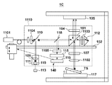
FIG. 11 is a schematic diagram showing a configuration of a measuring apparatus 1C according to the fourth embodiment of the present invention. The measurement apparatus 1C has a function of causing the measurement light reflected by the measurement surface to interfere with the reference light reflected by the reference surface and measuring a change in the optical path length of the measurement light. In this embodiment, the heterodyne interference method It is embodied as a three-dimensional shape measuring apparatus provided with a non-contact type probe using the.

計測装置1Cは、主な構成として、光源1101と、ステージ102と、基準ミラー105と、検出部111と、干渉光学系1110と、オートフォーカス系140とを有する。干渉光学系1110は、本実施形態では、光源1101からの光が計測面TSと基準ミラー105との間を2回往復するダブルパスのヘテロダイン干渉系を構成する。また、計測装置1Cにおいて、干渉光学系1110は、非接触型プローブ(光プローブ)として機能する。本実施形態では、計測光が集光レンズの中心を往復するため、集光レンズの周辺を計測光が往復する場合の構成と比較して、かかる集光レンズの設計及び製造をより簡便にすることができる。   The measurement apparatus 1C includes a light source 1101, a stage 102, a reference mirror 105, a detection unit 111, an interference optical system 1110, and an autofocus system 140 as main components. In the present embodiment, the interference optical system 1110 constitutes a double-pass heterodyne interference system in which light from the light source 1101 reciprocates twice between the measurement surface TS and the reference mirror 105. In the measuring apparatus 1C, the interference optical system 1110 functions as a non-contact type probe (optical probe). In this embodiment, since the measurement light reciprocates around the center of the condensing lens, the design and manufacture of the condensing lens can be made simpler than the configuration in which the measurement light reciprocates around the condensing lens. be able to.

光源1101から射出された光(平行光)は、ステージ102に保持された干渉光学系1110の偏光ビームスプリッタ181に入射する。光源1101は、波長及び偏光方向が互いに異なる2つの光、本実施形態では、偏光方向が互いに直交するS偏光の光とP偏光の光とを射出する。従って、光源1101からの光のうち、S偏光の光は偏光ビームスプリッタ181で反射されてZ軸と略平行な光となり、λ/4板104に入射する。また、光源1101からの光のうち、P偏光の光は偏光ビームスプリッタ181を透過してY軸と略平行な光となり、参照面としてのコーナーキューブ112に入射する。   Light (parallel light) emitted from the light source 1101 enters the polarization beam splitter 181 of the interference optical system 1110 held on the stage 102. The light source 1101 emits two lights having different wavelengths and polarization directions, and in this embodiment, S-polarized light and P-polarized light whose polarization directions are orthogonal to each other. Therefore, of the light from the light source 1101, the S-polarized light is reflected by the polarization beam splitter 181 to become light substantially parallel to the Z axis and enters the λ / 4 plate 104. Of the light from the light source 1101, P-polarized light is transmitted through the polarization beam splitter 181 to become light substantially parallel to the Y axis, and enters the corner cube 112 as a reference surface.

λ/4板104に入射した光は、λ/4板104を透過して円偏光の光となり、基準ミラー(基準面)105で反射される。基準ミラー105で反射された光は、λ/4板104を再び透過してP偏光の光となり、偏光ビームスプリッタ181を透過してλ/4板107に入射する。λ/4板107に入射した光は、λ/4板107を透過して円偏光の光となり、集光レンズ1102を介して、計測ステージ117に保持された計測面TSの上に集光される(計測面TSの上に焦点を結ぶ)。計測面TSで反射された光は、集光レンズ1102を透過して平行光となり、λ/4板107に入射する。λ/4板107に入射した光は、λ/4板107を透過してS偏光の光となり、偏光ビームスプリッタ181で反射され、コーナーキューブ112に入射する。コーナーキューブ112で反射された光は、偏光ビームスプリッタ181で反射され、λ/4板107及び集光レンズ1102を介して、再度、計測面TSの上に集光される。この際、計測面TSで反射された光は、集光レンズ1102を透過して平行光となり、λ/4板107に入射する。以下では、計測面TSで2回反射された光を計測光と称する。λ/4板107に入射した計測光は、λ/4板107を透過してP偏光の光となり、偏光ビームスプリッタ181を透過してλ/4板104に入射する。λ/4板104に入射した光は、λ/4板104を透過して円偏光の光となり、基準ミラー(基準面)105で反射される。基準ミラー105で反射された光は、λ/4板104を再び透過してS偏光の光となり、偏光ビームスプリッタ181で反射され、ハーフミラー119で反射した後、レンズ109及びフォトダイオード110で構成された検出部111に入射する。   The light that has entered the λ / 4 plate 104 passes through the λ / 4 plate 104 and becomes circularly polarized light, and is reflected by the reference mirror (reference surface) 105. The light reflected by the reference mirror 105 passes through the λ / 4 plate 104 again to become P-polarized light, passes through the polarization beam splitter 181, and enters the λ / 4 plate 107. The light incident on the λ / 4 plate 107 passes through the λ / 4 plate 107 and becomes circularly polarized light, and is condensed on the measurement surface TS held on the measurement stage 117 via the condenser lens 1102. (Focus on the measurement surface TS). The light reflected by the measurement surface TS passes through the condenser lens 1102 and becomes parallel light, and enters the λ / 4 plate 107. The light incident on the λ / 4 plate 107 passes through the λ / 4 plate 107 to become S-polarized light, is reflected by the polarization beam splitter 181, and enters the corner cube 112. The light reflected by the corner cube 112 is reflected by the polarization beam splitter 181, and is condensed again on the measurement surface TS via the λ / 4 plate 107 and the condenser lens 1102. At this time, the light reflected by the measurement surface TS passes through the condenser lens 1102 and becomes parallel light and enters the λ / 4 plate 107. Hereinafter, the light reflected twice by the measurement surface TS is referred to as measurement light. The measurement light incident on the λ / 4 plate 107 passes through the λ / 4 plate 107 to become P-polarized light, passes through the polarization beam splitter 181, and enters the λ / 4 plate 104. The light that has entered the λ / 4 plate 104 passes through the λ / 4 plate 104 and becomes circularly polarized light, and is reflected by the reference mirror (reference surface) 105. The light reflected by the reference mirror 105 is transmitted again through the λ / 4 plate 104 to become S-polarized light, reflected by the polarization beam splitter 181, reflected by the half mirror 119, and then constituted by the lens 109 and the photodiode 110. Is incident on the detected unit 111.

一方、コーナーキューブ112に入射した光は、コーナーキューブ112で入射した方向に反射され、偏光ビームスプリッタ181に入射する。以下では、計測面TSで反射されることなく、コーナーキューブ112で反射された光を参照光と称する。偏光ビームスプリッタ181に入射した参照光は、偏光ビームスプリッタ181を透過し、偏光ビームスプリッタ181で反射された計測光とともに、検出部111に入射する。検出部111では、計測光と参照光との干渉光が検出され、かかる干渉光に対応する干渉信号、本実施形態では、ヘテロダイン干渉信号が取得される。処理部113は、検出部111で検出された干渉信号に基づいて、計測光の光路長の変化を求める。   On the other hand, the light incident on the corner cube 112 is reflected in the direction incident on the corner cube 112 and enters the polarization beam splitter 181. Hereinafter, the light reflected by the corner cube 112 without being reflected by the measurement surface TS is referred to as reference light. The reference light incident on the polarization beam splitter 181 passes through the polarization beam splitter 181 and enters the detection unit 111 together with the measurement light reflected by the polarization beam splitter 181. The detection unit 111 detects interference light between the measurement light and the reference light, and acquires an interference signal corresponding to the interference light, in this embodiment, a heterodyne interference signal. The processing unit 113 obtains a change in the optical path length of the measurement light based on the interference signal detected by the detection unit 111.

計測装置1Cにおいては、干渉光学系1110から光源1101に戻る、所謂、戻り光があっても、ファラデーローテーター等を用いてレーザ出力が安定するような機能を備えた光源を光源1101として使用するとよい。これは、計測装置1Cにおいては、計測装置1Aとは異なり、計測面TSで反射された光やコーナーキューブ112で反射された光が、光源1101から射出された光の光路を戻るようにして、光源1101に入射しやすいためである。また、干渉光学系1110には、図11に示すように、減光光学フィルタ1103及び1104が配置されている。減光光学フィルタ1103及び1104は、例えば、NDフィルタや偏光板で構成され、光の強度を低下させる機能を有する。計測装置1Cでは、減光光学フィルタ1103及び1104を用いることで、光源1101に戻る光の強度を減衰させて、かかる戻り光による計測精度の低下を防止することが可能となる。   In the measuring apparatus 1C, a light source having a function of stabilizing the laser output using a Faraday rotator or the like may be used as the light source 1101 even when there is so-called return light that returns from the interference optical system 1110 to the light source 1101. . This is different from the measurement apparatus 1A in the measurement apparatus 1C, in which the light reflected by the measurement surface TS and the light reflected by the corner cube 112 return the optical path of the light emitted from the light source 1101. This is because the light easily enters the light source 1101. Further, as shown in FIG. 11, the interference optical system 1110 is provided with dimming optical filters 1103 and 1104. The neutral density optical filters 1103 and 1104 are composed of, for example, an ND filter or a polarizing plate, and have a function of reducing light intensity. In the measurement apparatus 1C, by using the dimming optical filters 1103 and 1104, it is possible to attenuate the intensity of the light returning to the light source 1101 and prevent the measurement accuracy from being lowered due to the return light.

また、ハーフミラー118とフォーカス状態を計測するための計測部115との間には、偏光板1105を配置してもよい。偏光板1105は、その偏光特性を用いて、ハーフミラー118で反射された光のうち、フォーカス状態の計測に必要な計測面TSで反射した光のみを透過させ、フォーカス状態の計測に必要でない参照光などを取り除くことができる。従って、計測部115において、SN比のよい光を検出することが可能となり、フォーカス状態を高精度に計測することができる。   Further, a polarizing plate 1105 may be disposed between the half mirror 118 and the measuring unit 115 for measuring the focus state. The polarizing plate 1105 transmits only the light reflected by the measurement surface TS necessary for the measurement of the focus state out of the light reflected by the half mirror 118 using the polarization characteristic, and is not necessary for the measurement of the focus state. Light can be removed. Therefore, the measuring unit 115 can detect light with a good S / N ratio, and can measure the focus state with high accuracy.

また、計測装置1Cでは、X軸駆動部151及びY軸駆動部152によってステージ102をXY平面内で移動させながら、検出部111でヘテロダイン干渉信号を取得する。換言すれば、干渉光学系1110からの光(集光レンズ1102によって集光される光)が計測面TSの上の複数の位置に入射するように干渉光学系1110(を保持するステージ102)を位置決めしながら、検出部111でヘテロダイン干渉信号を取得する。そして、検出部111で取得されたヘテロダイン干渉信号に基づいて計測光の光路長の変化を求めることで、計測面TSの形状を計測することができる。   In the measuring apparatus 1C, the detection unit 111 acquires a heterodyne interference signal while the stage 102 is moved in the XY plane by the X-axis driving unit 151 and the Y-axis driving unit 152. In other words, the interference optical system 1110 (holding stage 102) is set so that light from the interference optical system 1110 (light condensed by the condensing lens 1102) enters a plurality of positions on the measurement surface TS. While positioning, a heterodyne interference signal is acquired by the detection unit 111. The shape of the measurement surface TS can be measured by obtaining a change in the optical path length of the measurement light based on the heterodyne interference signal acquired by the detection unit 111.

計測装置1Cでは、計測装置1Aと同様に、集光レンズ1102の焦点深度の範囲内に計測面TSの上の計測箇所が収まる(位置する)ように、集光レンズ1102の光軸方向における集光レンズ1102の位置が制御されている。これにより、計測面TSで反射されて集光レンズ1102に入射した光(計測光)は、平行光として偏光ビームスプリッタ181に戻る。そして、コーナーキューブ112で反射された光(参照光)とともに検出部111で検出される。従って、計測光の波面収差が小さいことにより検出部111において良好な干渉光が得られるため、良好なヘテロダイン信号が検出される。更に、計測装置1Cにおいては、計測光が集光レンズの中心部を往復するため、集光レンズの周辺を計測光が往復する場合と比較して、より波面収差の小さな高性能な集光レンズの設計及び製造をより簡便に行うことができる。一般に、ダブルパスのヘテロダイン干渉系においては、計測光が集光レンズを2度往復するため、計測光が集光レンズを1度しか往復しないシングルパスの干渉系に比べ、波面収差は2倍程度になりうる。従って、干渉信号が劣化しうる。但し、計測装置1Cにおいては、計測光が集光レンズの中心部を往復するため、波面収差の小さな高性能な集光レンズで装置を構成することができる。このため、干渉光学系1110をダブルパスのヘテロダイン干渉系で構成した場合にも、計測装置1Cは、計測面TSの形状を高精度に計測することができる。具体的には、計測装置1Cは、干渉光学系1110を保持するステージ102をXY平面内で移動させながら、検出部111でヘテロダイン干渉信号を取得することで、計測面TSの形状を高精度に計測することができる。更に、計測光は、集光レンズ1102の中央部のみを通過するため、集光レンズ1102の設計及び製造が簡便となり、高精度、且つ、安価な3次元形状計測装置が具現化される。   In the measurement apparatus 1C, as in the measurement apparatus 1A, the collection lens 1102 in the optical axis direction is arranged so that the measurement location on the measurement surface TS is within the focal depth range of the collection lens 1102 (positioned). The position of the optical lens 1102 is controlled. Thereby, the light (measurement light) reflected by the measurement surface TS and incident on the condenser lens 1102 returns to the polarization beam splitter 181 as parallel light. Then, the detection unit 111 detects the light (reference light) reflected by the corner cube 112. Accordingly, a good heterodyne signal is detected because good interference light is obtained in the detection unit 111 due to the small wavefront aberration of the measurement light. Furthermore, in the measuring apparatus 1C, since the measurement light reciprocates in the central part of the condenser lens, a high-performance condenser lens with smaller wavefront aberration than in the case where the measurement light reciprocates around the condenser lens. Can be more easily designed and manufactured. In general, in a double-pass heterodyne interference system, the measurement light reciprocates twice through the condenser lens, so that the wavefront aberration is about twice that of a single-pass interference system in which the measurement light reciprocates only once through the condenser lens. Can be. Therefore, the interference signal can be degraded. However, in the measurement apparatus 1C, since the measurement light reciprocates in the center of the condenser lens, the apparatus can be configured with a high-performance condenser lens with small wavefront aberration. For this reason, even when the interference optical system 1110 is configured by a double-pass heterodyne interference system, the measurement apparatus 1C can measure the shape of the measurement surface TS with high accuracy. Specifically, the measurement apparatus 1C acquires the heterodyne interference signal by the detection unit 111 while moving the stage 102 that holds the interference optical system 1110 in the XY plane, thereby accurately measuring the shape of the measurement surface TS. It can be measured. Furthermore, since the measurement light passes only through the central portion of the condensing lens 1102, the design and manufacture of the condensing lens 1102 is simplified, and a highly accurate and inexpensive three-dimensional shape measuring apparatus is realized.

以上、本発明の好ましい実施形態について説明したが、本発明はこれらの実施形態に限定されないことはいうまでもなく、その要旨の範囲内で種々の変形及び変更が可能である。例えば、上述した実施形態では、集光レンズによって集光される光のフォーカス状態を検知し、かかるフォーカス状態に基づいて、フォーカス状態(集光レンズと計測面との間の距離等)を調整している。しかし、それには限定されず、計測面の目標形状を表す形状情報を記憶する記憶部を用意し、かかる記憶部に記憶された形状情報に基づいて、フォーカス状態を調整してもよい。   As mentioned above, although preferable embodiment of this invention was described, it cannot be overemphasized that this invention is not limited to these embodiment, A various deformation | transformation and change are possible within the range of the summary. For example, in the above-described embodiment, the focus state of the light collected by the condenser lens is detected, and the focus state (the distance between the condenser lens and the measurement surface, etc.) is adjusted based on the focus state. ing. However, the present invention is not limited to this, and a storage unit that stores shape information representing the target shape of the measurement surface may be prepared, and the focus state may be adjusted based on the shape information stored in the storage unit.

Claims (11)

計測面で反射した計測光と参照面で反射した参照光とを干渉させて得られる干渉信号から前記計測面を計測する計測装置であって、
前記計測面に入射する光を集光する集光レンズを含み、前記計測光と前記参照光とを干渉させる干渉光学系と、
前記集光レンズの焦点深度の範囲内に前記計測面の上の計測箇所が位置するように、前記集光レンズによって集光される光のフォーカス状態を調整する調整部と、を有し、
前記調整部により前記フォーカス状態が調整された状態で前記干渉信号を取得する、
ことを特徴とする計測装置。
A measurement device that measures the measurement surface from an interference signal obtained by causing interference between the measurement light reflected by the measurement surface and the reference light reflected by the reference surface,
An interference optical system that includes a condensing lens that condenses the light incident on the measurement surface, and causes the measurement light and the reference light to interfere with each other;
An adjustment unit that adjusts a focus state of light collected by the condenser lens so that a measurement point on the measurement surface is located within a range of a focal depth of the condenser lens;
Obtaining the interference signal in a state in which the focus state is adjusted by the adjustment unit;
A measuring device characterized by that.
前記フォーカス状態を計測する計測部を更に有し、
前記調整部は、前記計測部で計測されたフォーカス状態に基づいて前記フォーカス状態を調整する、ことを特徴とする請求項1に記載の計測装置。
A measuring unit for measuring the focus state;
The measurement apparatus according to claim 1, wherein the adjustment unit adjusts the focus state based on the focus state measured by the measurement unit.
前記計測面の目標形状を表す形状情報を記憶する記憶部を更に有し、
前記調整部は、前記記憶部に記憶された形状情報に基づいて前記フォーカス状態を調整する、ことを特徴とする請求項1に記載の計測装置。
A storage unit that stores shape information representing a target shape of the measurement surface;
The measurement apparatus according to claim 1, wherein the adjustment unit adjusts the focus state based on shape information stored in the storage unit.
前記調整部は、前記集光レンズの光軸に沿った方向に前記集光レンズを移動する駆動部を含む、ことを特徴とする請求項1乃至3のうちいずれか1項に記載の計測装置。   The measuring apparatus according to claim 1, wherein the adjustment unit includes a drive unit that moves the condenser lens in a direction along an optical axis of the condenser lens. . 前記干渉光学系を保持するステージを更に有し、
前記調整部は、前記集光レンズの光軸に沿った方向に前記ステージを移動する駆動部を含む、ことを特徴とする請求項1乃至3のうちいずれか1項に記載の計測装置。
A stage for holding the interference optical system;
The measuring apparatus according to claim 1, wherein the adjustment unit includes a drive unit that moves the stage in a direction along an optical axis of the condenser lens.
前記干渉光学系において、光源からの光が基準面及び前記計測面のそれぞれで2回ずつ反射する、ことを特徴とする請求項1乃至5のうちいずれか1項に記載の計測装置。   6. The measurement apparatus according to claim 1, wherein in the interference optical system, light from a light source is reflected twice on each of a reference surface and the measurement surface. 前記集光レンズの光軸方向に沿った前記干渉光学系の位置を計測するための計測用干渉光学系を有し、
前記調整部により前記フォーカス状態が調整された状態で前記計測用干渉光学系を介して前記干渉光学系の位置を計測し、該位置と前記干渉信号とに基づいて前記計測面を計測する、
ことを特徴とする請求項1乃至6のうちいずれか1項に記載の計測装置。
An interference optical system for measurement for measuring the position of the interference optical system along the optical axis direction of the condenser lens;
Measuring the position of the interference optical system through the measurement interference optical system in a state where the focus state is adjusted by the adjustment unit, and measuring the measurement surface based on the position and the interference signal;
The measuring apparatus according to any one of claims 1 to 6, wherein
前記干渉光学系において、光源からの光が基準面及び前記計測面のそれぞれで2回ずつ反射する間に、前記集光レンズを通過する光が前記集光レンズの中心部を往復する、ことを特徴とする請求項6に記載の計測装置。   In the interference optical system, the light passing through the condenser lens reciprocates in the central portion of the condenser lens while the light from the light source is reflected twice on each of the reference surface and the measurement surface. The measuring device according to claim 6, wherein 前記干渉信号を得るための光源として、波長及び偏光方向が互いに異なる2つの光を射出する光源を有する、ことを特徴とする請求項1乃至8のうちいずれか1項に記載の計測装置。   The measurement apparatus according to claim 1, further comprising: a light source that emits two lights having different wavelengths and polarization directions as a light source for obtaining the interference signal. 前記集光レンズによって集光された光が前記計測面の上の複数の計測箇所に順次入射するように、前記干渉光学系を位置決めする位置決め機構と、
前記複数の計測箇所それぞれに関して得られた前記干渉信号に基づいて前記計測面の形状を求める処理部と、
を有することを特徴とする請求項1乃至9のうちいずれか1項に記載の計測装置。
A positioning mechanism that positions the interference optical system so that light collected by the condenser lens sequentially enters a plurality of measurement points on the measurement surface;
A processing unit for obtaining the shape of the measurement surface based on the interference signal obtained for each of the plurality of measurement points;
The measuring apparatus according to claim 1, further comprising:
曲率を有する前記計測面を計測する、ことを特徴とする請求項1乃至10のうちいずれか1項に記載の計測装置。   The measurement apparatus according to claim 1, wherein the measurement surface having a curvature is measured.
JP2012165139A 2012-03-09 2012-07-25 Measuring apparatus Pending JP2013213802A (en)

Priority Applications (2)

Application Number Priority Date Filing Date Title
JP2012165139A JP2013213802A (en) 2012-03-09 2012-07-25 Measuring apparatus
US13/775,828 US9062967B2 (en) 2012-03-09 2013-02-25 Measurement apparatus for measuring a surface shape of an object based on an interference signal

Applications Claiming Priority (3)

Application Number Priority Date Filing Date Title
JP2012053686 2012-03-09
JP2012165139A JP2013213802A (en) 2012-03-09 2012-07-25 Measuring apparatus

Publications (2)

Publication Number Publication Date
JP2013213802A true JP2013213802A (en) 2013-10-17
JP2013213802A5 JP2013213802A5 (en) 2015-09-10

Family

ID=49113868

Family Applications (1)

Application Number Title Priority Date Filing Date
JP2012165139A Pending JP2013213802A (en) 2012-03-09 2012-07-25 Measuring apparatus

Country Status (2)

Country Link
US (1) US9062967B2 (en)
JP (1) JP2013213802A (en)

Cited By (1)

* Cited by examiner, † Cited by third party
Publication number Priority date Publication date Assignee Title
CN103983205A (en) * 2014-04-30 2014-08-13 天津大学 Composite measurement system and measurement method for micro-array complex surface optical element

Families Citing this family (2)

* Cited by examiner, † Cited by third party
Publication number Priority date Publication date Assignee Title
CN104034264B (en) * 2014-06-14 2017-02-15 哈尔滨工业大学 Traceable accurate measurement ruler based semiconductor laser distance measurement device and method
JP2019168339A (en) * 2018-03-23 2019-10-03 株式会社コベルコ科研 Shape measurement device and shape measurement method

Citations (2)

* Cited by examiner, † Cited by third party
Publication number Priority date Publication date Assignee Title
JP2001343222A (en) * 2000-06-05 2001-12-14 Canon Inc Method and apparatus for measuring three-dimensional shape
JP2009145095A (en) * 2007-12-12 2009-07-02 Canon Inc Three-dimensional shape measuring device

Family Cites Families (5)

* Cited by examiner, † Cited by third party
Publication number Priority date Publication date Assignee Title
US4353650A (en) 1980-06-16 1982-10-12 The United States Of America As Represented By The United States Department Of Energy Laser heterodyne surface profiler
US5122648A (en) * 1990-06-01 1992-06-16 Wyko Corporation Apparatus and method for automatically focusing an interference microscope
US5784164A (en) * 1997-03-20 1998-07-21 Zygo Corporation Method and apparatus for automatically and simultaneously determining best focus and orientation of objects to be measured by broad-band interferometric means
EP1519144A1 (en) * 2003-09-29 2005-03-30 Nederlandse Organisatie voor toegepast-natuurwetenschappelijk onderzoek TNO Free-form optical surface measuring apparatus and method
EP1610088B1 (en) * 2004-06-22 2007-01-03 Polytec GmbH Device for optically measuring an object

Patent Citations (2)

* Cited by examiner, † Cited by third party
Publication number Priority date Publication date Assignee Title
JP2001343222A (en) * 2000-06-05 2001-12-14 Canon Inc Method and apparatus for measuring three-dimensional shape
JP2009145095A (en) * 2007-12-12 2009-07-02 Canon Inc Three-dimensional shape measuring device

Cited By (1)

* Cited by examiner, † Cited by third party
Publication number Priority date Publication date Assignee Title
CN103983205A (en) * 2014-04-30 2014-08-13 天津大学 Composite measurement system and measurement method for micro-array complex surface optical element

Also Published As

Publication number Publication date
US20130235386A1 (en) 2013-09-12
US9062967B2 (en) 2015-06-23

Similar Documents

Publication Publication Date Title
JP6076589B2 (en) Displacement detector
US8810807B2 (en) Displacement detecting device
JP5599790B2 (en) Method and apparatus for reducing optical interference and crosstalk of double optical tweezers using one laser light source
CN102385170B (en) Optical system for measuring and regulating center deviation of optics lens at high precision
JP6040992B2 (en) Integrated optical assembly improvements
JP2013545976A (en) Apparatus, optical assembly, method of inspecting or measuring an object, and method of manufacturing a structure
KR20100134609A (en) Apparatus and method for measuring surface topography of an object
JP2016014600A (en) Displacement detector
JPH0455243B2 (en)
JP2012150301A (en) Optical device
JP2004317424A (en) Autocollimator
JP2015052537A (en) Measuring device
JP2013213802A (en) Measuring apparatus
JPS5979104A (en) Optical device
TW201306981A (en) Real time monitoring system for depth of laser processing and method thereof
US20140071457A1 (en) Method and System for Tilt and Height Control of a Substrate Surface in an Inspection System
JP2014145684A (en) Measuring device
US20150070710A1 (en) Measurement apparatus
JP5969274B2 (en) Position detection device
JP2018197659A (en) Displacement detection device
JP2002250609A (en) Gap-measuring device, gap-measuring method, and manufacturing method of optical system
JP5217350B2 (en) Eccentricity measuring device
JP2006112872A (en) Compact angle sensor
JP2011099914A (en) Polarizing optical element
JP3410800B2 (en) Vibration resistant interferometer

Legal Events

Date Code Title Description
A521 Request for written amendment filed

Free format text: JAPANESE INTERMEDIATE CODE: A523

Effective date: 20150727

A621 Written request for application examination

Free format text: JAPANESE INTERMEDIATE CODE: A621

Effective date: 20150727

A131 Notification of reasons for refusal

Free format text: JAPANESE INTERMEDIATE CODE: A131

Effective date: 20160530

A977 Report on retrieval

Free format text: JAPANESE INTERMEDIATE CODE: A971007

Effective date: 20160531

A02 Decision of refusal

Free format text: JAPANESE INTERMEDIATE CODE: A02

Effective date: 20161121