JP2013207555A - Pon system, station side device and operation method therefor, and access control device - Google Patents
Pon system, station side device and operation method therefor, and access control device Download PDFInfo
- Publication number
- JP2013207555A JP2013207555A JP2012074478A JP2012074478A JP2013207555A JP 2013207555 A JP2013207555 A JP 2013207555A JP 2012074478 A JP2012074478 A JP 2012074478A JP 2012074478 A JP2012074478 A JP 2012074478A JP 2013207555 A JP2013207555 A JP 2013207555A
- Authority
- JP
- Japan
- Prior art keywords
- access control
- control unit
- pon
- mode
- home
- Prior art date
- Legal status (The legal status is an assumption and is not a legal conclusion. Google has not performed a legal analysis and makes no representation as to the accuracy of the status listed.)
- Pending
Links
Images


Abstract
Description
本発明は、局側装置と複数の宅側装置とをツリー構造の通信回線で接続したPON(Passive Optical Network )システムと、このシステムの構成要素である局側装置と、この局側装置の運用方法及びアクセス制御装置に関する。 The present invention relates to a PON (Passive Optical Network) system in which a station-side device and a plurality of home-side devices are connected through a communication line having a tree structure, a station-side device that is a component of the system, and an operation of the station-side device The present invention relates to a method and an access control apparatus.
PONシステムは、P2MP(Point to Multi Point)の接続形態における光分岐を無電力で行う光通信システムであり、局側装置と、この局側装置を頂点として分岐する一芯の光ファイバ網よりなるツリー構造のPON回線と、その分岐した光ファイバの終端にそれぞれ接続された複数の宅側装置とを備えている(例えば、特許文献1〜3参照)。
このPONシステムにおいては、半導体レーザ等の光源を直接或いは外部変調したNRZ(Non-Return to Zero)光信号を伝送し、所定の情報を送受信する。
The PON system is an optical communication system that performs optical branching in a P2MP (Point to Multi Point) connection mode without power, and includes a station-side device and a single-core optical fiber network that branches from the station-side device as a vertex. It includes a tree-structured PON line and a plurality of home-side devices connected to the ends of the branched optical fibers (see, for example,
In this PON system, a NRZ (Non-Return to Zero) optical signal obtained by directly or externally modulating a light source such as a semiconductor laser is transmitted, and predetermined information is transmitted and received.
かかるPONシステムでは、局側装置が送信する光信号よりなる下りフレームは、各宅側装置に放送形式で伝送される。宅側装置は、ディスカバリの際に局側装置から通知された、下りフレームのプリアンブルに含まれる論理リンク識別子(例えば、IEEE Std 802.3TM−2008に規定されるPONの場合はLLID。以下、代表的にLLIDと記す場合がある。)を参照して、自局宛(マルチキャストの場合も含む。)の下りフレームを受信し、それ以外の下りフレームを廃棄する。 In such a PON system, a downstream frame composed of an optical signal transmitted from a station side device is transmitted to each home side device in a broadcast format. The home side apparatus notifies the logical link identifier (for example, LLID in the case of PON defined in IEEE Std 802.3 TM- 2008), which is notified from the station side apparatus during discovery and is included in the preamble of the downstream frame. Referring to LLID as a representative example), a downlink frame addressed to the own station (including a case of multicast) is received, and the other downlink frames are discarded.
逆に、各宅側装置がPON回線に送出する光信号よりなる上りフレームについては、衝突を防止すべく、局側装置がLLIDごとに時分割で多重アクセス制御を行っている。従って、局側装置は、各宅側装置からの上り光信号をバースト的に受信する。 On the contrary, for the upstream frame composed of the optical signal transmitted from each home side apparatus to the PON line, the station side apparatus performs multiple access control by time division for each LLID in order to prevent collision. Accordingly, the station-side device receives the upstream optical signal from each home-side device in a burst manner.
PONシステムの局側装置には、アクセス制御プロトコルに基づいてPON区間の上りフレームの多重アクセス制御を行うアクセス制御部(以下、「アクセス制御装置」ともいう。)が含まれている。例えば、IEEE Std 802.3TM−2008やIEEE Std 802.3avTM−2009に規定されるPONの場合は、MPCP(MultiPoint Control Protocol )が上記アクセス制御プロトコルに相当する。 The station-side device of the PON system includes an access control unit (hereinafter also referred to as “access control device”) that performs multiple access control of uplink frames in the PON section based on an access control protocol. For example, in the case of PON defined by IEEE Std 802.3 TM- 2008 and IEEE Std 802.3av TM- 2009, MPCP (MultiPoint Control Protocol) corresponds to the above access control protocol.
このアクセス制御装置は、通常、複数のLSI(Large Scale Integrated Circuit )を制御基板に実装して構成されており、プログラマブルな論理回路(Field-Programmable Gate Array :FPGA)やマイクロプロセッサ(Micro-Processing Unit:MPU)のメモリに予め記憶させたコンピュータプログラムに従って動作する。 This access control device is usually configured by mounting a plurality of LSIs (Large Scale Integrated Circuits) on a control board, and is configured with a programmable logic circuit (Field-Programmable Gate Array: FPGA) or a microprocessor (Micro-Processing Unit). : MPU) according to a computer program stored in advance in the memory.
従って、アクセス制御装置に対する機能の追加や変更(以下、これらを纏めて「変更等」という。)を行うには、論理回路やマイクロプロセッサが実行するコンピュータプログラムを更新する必要がある。
しかし、コンピュータプログラムの更新作業には、通常、アクセス制御装置のプロセッサ等を初期状態にリセットしてから、変更等の後の機能で再起動をかける手順が含まれるので、リセットから再起動が完了するまでの更新作業中は、上位ネットワークとPON回線のデータ転送を停止せざるを得ないという問題があった。
Therefore, in order to add or change functions to the access control device (hereinafter collectively referred to as “changes”), it is necessary to update a computer program executed by a logic circuit or a microprocessor.
However, updating the computer program usually includes a procedure to reset the processor of the access control device to the initial state and then restart it with a later function, etc., so the restart from the reset is completed During the update work up to this point, there was a problem that the data transfer between the host network and the PON line had to be stopped.
かかる更新に伴う通信断時間は、電話や映像信号の伝送に求められる通信品質を維持できるほど短くなく、例えば、MPCPで規定するタイムアウト時間(1秒間)よりも長時間となるのが普通である。
このため、従来では、電話などの通信が不通となる被害を最小限に抑えるために、通信事業者の作業員が、トラフィックが比較的少ない深夜の時間帯に、タイミングを見計らってコンピュータプログラムの更新を行うといった作業を行っており、アクセス制御装置に対する機能の変更等に非常に手間がかかっていた。
The communication interruption time associated with such an update is not short enough to maintain the communication quality required for transmission of telephones and video signals. For example, the communication interruption time is usually longer than the timeout time (1 second) defined by MPCP. .
For this reason, traditionally, in order to minimize the damage caused by communication interruptions such as telephone calls, operators of telecommunications carriers have updated computer programs in anticipation of timing in the midnight hours when traffic is relatively low. It has been a lot of work to change the functions of the access control device.
そこで、本出願人は、複数のPON回線にそれぞれ対応するアクセス制御部を備え、複数のアクセス制御部のうちの特定のアクセス制御部が「縮退モード」を実行する局側装置を、既に提案している(特願2011−186211の明細書参照)。
ここで、「縮退モード」とは、特定のアクセス制御部が、自身が通常管理するPON回線に加えて他のPON回線の上り多重アクセス制御を引き受け、他のPON回線に対応する他のアクセス制御部に通信フレームが疎通しない状態にする動作モードのことをいう。
Therefore, the present applicant has already proposed a station-side apparatus that includes an access control unit corresponding to each of a plurality of PON lines, and in which a specific access control unit among the plurality of access control units executes the “degenerate mode”. (See the specification of Japanese Patent Application No. 2011-186221).
Here, “degenerate mode” means that a specific access control unit assumes uplink multiple access control of other PON lines in addition to the PON line normally managed by itself, and other access control corresponding to other PON lines. This is an operation mode in which a communication frame is not communicated with a part.
従って、局側装置を縮退モードにすれば、アクティブなアクセス制御部が他のPON回線の通信を担うので、PON回線でのデータ転送を停止させずに、通信フレームが疎通しなくなったスタンバイのアクセス制御部の変更等を行うことができる。
しかし、縮退モードによってスタンバイとなったアクセス制御部のコンピュータプログラムを更新する場合には、当該アクセス制御部とこれを管理する管理制御部とがそれぞれ有するデータ内容に不整合が生じ得るという、新たな課題が生じる。
Therefore, if the station side device is set to the degenerate mode, the active access control unit is responsible for communication with other PON lines, so the standby access in which communication frames are not communicated without stopping the data transfer on the PON line. The control unit can be changed.
However, when updating the computer program of the access control unit that has become standby due to the degenerate mode, a new inconsistency may occur between the data contents of the access control unit and the management control unit that manages the access control unit. Challenges arise.
例えば、縮退モードによりスタンバイとなったアクセス制御部にファームウェアなどのコンピュータプログラムの更新を行っている間に、新たな宅側装置のリンクアップや既存の宅側装置のリンクダウンが発生した場合には、アクティブなアクセス制御部がその宅側装置のLLIDを管理制御部に通知し、管理制御部は通知されたLLIDを記録又は削除するが、スタンバイのアクセス制御部にはそのLLIDを通知できない。
従って、スタンバイのアクセス制御部と管理制御部が共通に保持すべきデータの内容が整合しなくなり、当該アクセス制御部が通常回線制御に復帰した場合に、管理制御部がそのアクセス制御部を適切に管理できなくなるという問題がある。
For example, when a link up of a new home side device or a link down of an existing home side device occurs while updating the computer program such as firmware to the access control unit that has become standby due to the reduced mode The active access control unit notifies the management control unit of the LLID of the home device, and the management control unit records or deletes the notified LLID, but cannot notify the standby access control unit of the LLID.
Therefore, when the contents of data that should be held in common by the standby access control unit and the management control unit become inconsistent and the access control unit returns to normal line control, the management control unit appropriately sets the access control unit. There is a problem that it becomes impossible to manage.
また、管理制御部に対してファームウェアなどのコンピュータプログラムの更新を行っている間は、管理制御部がアクセス制御部からのメッセージを受信せずに廃棄するため、その更新中に宅側装置のリンクアップや既存の宅側装置のリンクダウンが発生した場合に、アクセス制御部がリンクアップ又はリンクダウンしたLLIDの記録又は削除を行ってそのLLIDを管理制御部に通知しても、管理制御部がそれを受信できない。
従って、この場合、局側装置の動作モードに関係なく、アクセス制御部と管理制御部が共通に保持すべきデータの内容が整合しなくなり、管理制御部がアクセス制御部を適切に管理できなくなるという問題がある。
Also, while updating the computer program such as firmware to the management control unit, the management control unit discards the message without receiving the message from the access control unit. If the access control unit records or deletes the link-up or link-down LLID and notifies the management control unit of the link up or link-down of the existing home side device, the management control unit I can't receive it.
Therefore, in this case, regardless of the operation mode of the station side device, the contents of data that the access control unit and the management control unit should hold in common are not consistent, and the management control unit cannot properly manage the access control unit. There's a problem.
本発明は、このような問題点に鑑み、複数のPON回線に対する上り多重アクセス制御を一部のアクセス制御部に担わせる縮退モードが可能な局側装置において、アクセス制御部と管理制御部が共通に保持すべきデータ内容の不整合を防止すること目的とする。 In view of such a problem, the present invention provides a common access control unit and management control unit in a station-side apparatus capable of a degenerate mode in which some access control units are responsible for uplink multiple access control for a plurality of PON lines. The purpose is to prevent inconsistency of data contents to be stored in the database.
(1) 第1発明に係る局側装置は、複数の宅側装置とPONシステムを構成する局側装置であって、複数のPON回線に対応して設けられたアクセス制御部と、複数の前記アクセス制御部とそれぞれ通信して当該アクセス制御部を管理し、少なくとも1つの前記アクセス制御部に対して下記に定義する通常モードと縮退モードを含む動作モードを指示可能な管理制御部と、前記縮退モードの実行中は前記宅側装置のリンク状態の変更を禁止する変更禁止部と、を備えていることを特徴とする。 (1) A station-side device according to a first invention is a station-side device that forms a PON system with a plurality of home-side devices, the access control unit provided corresponding to a plurality of PON lines, A management control unit capable of communicating with each of the access control units to manage the access control unit, and instructing at least one of the access control units to specify an operation mode including a normal mode and a degeneration mode defined below, and the degeneration A change prohibiting unit that prohibits a change in the link state of the home-side device during execution of the mode.
通常モード:各々のアクセス制御部が、自身が通常管理するPON回線の上り多重アクセス制御である通常回線制御を行う動作モード
縮退モード:特定のアクセス制御部が、自身が通常管理するPON回線と他のPON回線の上り多重アクセス制御である複数回線制御を行い、他のPON回線に対応する他のアクセス制御部に通信フレームを疎通させない動作モード
Normal mode: An operation mode in which each access control unit performs normal line control that is uplink multiple access control of the PON line that is normally managed. Degenerate mode: PON line that the specific access control part normally manages and others Mode that performs multiple line control, which is uplink multiple access control for PON lines, and does not allow communication frames to communicate with other access control units corresponding to other PON lines
第1発明に係る局側装置によれば、変更禁止部が、アクセス制御部が縮退モードを実行する間は宅側装置のリンク状態の変更を禁止するので、縮退モードによってスタンバイとなったアクセス制御部のコンピュータプログラムの更新を行っている間に、宅側装置のリンクアップやリンクダウンなどのリンク状態の変更が発生しない。
従って、スタンバイのアクセス制御部に対するコンピュータプログラムの更新前後で、当該アクセス制御部と管理制御部が共通に保持すべきデータ内容の不整合を防止することができる。
According to the station apparatus according to the first aspect of the present invention, the change prohibiting unit prohibits the change of the link state of the home apparatus while the access control unit executes the degenerate mode. While the computer program is being updated, link state changes such as link-up and link-down of the home device do not occur.
Accordingly, it is possible to prevent inconsistency in data contents that the access control unit and the management control unit should hold in common before and after the computer program is updated to the standby access control unit.
(2) 第1発明に係る局側装置において、前記変更禁止部による禁止処理は、具体的には、前記宅側装置に対するディスカバリウィンドウの開設を停止する処理を採用すればよい。この場合、新たな宅側装置のリンクアップに伴うリンク状態の変更を禁止することができる。
(3) また、前記変更禁止部による禁止処理は、前記宅側装置についてのMPCP及びOAMのリンクダウンの判定を停止する処理であってもよい。この場合、既存の宅側装置のリンクダウンに伴うリンク状態の変更を禁止することができる。
(2) In the station side apparatus according to the first aspect of the invention, the prohibition process by the change prohibition unit may specifically employ a process of stopping the establishment of a discovery window for the home side apparatus. In this case, the change of the link state accompanying the link up of the new home device can be prohibited.
(3) Moreover, the prohibition process by the change prohibition unit may be a process of stopping determination of MPCP and OAM link down for the home-side apparatus. In this case, it is possible to prohibit the change of the link state accompanying the link down of the existing home side apparatus.
(4) 第2発明に係る局側装置は、複数の宅側装置とPONシステムを構成する局側装置であって、複数のPON回線に対応して設けられたアクセス制御部と、複数の前記アクセス制御部とそれぞれ通信して当該アクセス制御部を管理し、少なくとも1つの前記アクセス制御部に対して上述の通常モードと縮退モードを含む動作モードを指示可能な管理制御部と、前記管理制御部と前記アクセス制御部との通信が不通である間は、前記宅側装置のリンク状態の変更を禁止する変更禁止部と、を備えていることを特徴とする。 (4) A station-side device according to a second invention is a station-side device that constitutes a PON system with a plurality of home-side devices, the access control unit provided corresponding to a plurality of PON lines, A management control unit capable of managing the access control unit by communicating with each of the access control units and instructing at least one of the access control units to include an operation mode including the normal mode and the degeneration mode; and the management control unit And a change prohibiting unit that prohibits a change in the link state of the home side device while communication with the access control unit is interrupted.
第2発明に係る局側装置によれば、変更禁止部が、管理制御部とアクセス制御部との通信が不通である間は、宅側装置のリンク状態の変更を禁止するので、管理制御部に対してコンピュータプログラムの更新を行っている間に、宅側装置のリンクアップやリンクダウンなどのリンク状態の変更が発生しない。
従って、管理制御部に対するコンピュータプログラムの更新前後で、アクセス制御部と管理制御部が共通に保持すべきデータの内容の不整合を防止することができる。
According to the station side apparatus according to the second aspect of the invention, since the change prohibition unit prohibits the change of the link state of the home side device while the communication between the management control unit and the access control unit is disconnected, the management control unit While the computer program is being updated, the link state change such as link up or link down of the home device does not occur.
Accordingly, it is possible to prevent inconsistencies in the contents of data that the access control unit and the management control unit should hold in common before and after the computer program is updated to the management control unit.
(5)(6) 第2発明に係る局側装置においても、前記変更禁止部による禁止処理は、具体的には、前記宅側装置に対するディスカバリウィンドウの開設を停止する処理や、前記宅側装置についてのMPCP及びOAMのリンクダウンの判定を停止する処理を採用すればよい。 (5) (6) Also in the station side device according to the second aspect of the invention, the prohibition process by the change prohibition unit is specifically a process for stopping the opening of a discovery window for the home side device, or the home side device. A process for stopping the determination of the link down of the MPCP and the OAM may be adopted.
(7) 第1発明に係る局側装置の運用方法は、第1発明に係る局側装置と実質同一のカテゴリが異なる方法発明であって、当該局側装置と同様の作用効果を奏する。
(8) 第2発明に係る局側装置の運用方法は、第2発明に係る局側装置と実質同一のカテゴリが異なる方法発明であって、当該局側装置と同様の作用効果を奏する。
(7) The operation method of the station-side device according to the first invention is a method invention having substantially the same category as that of the station-side device according to the first invention, and has the same effects as the station-side device.
(8) The operation method of the station-side device according to the second invention is a method invention having substantially the same category as that of the station-side device according to the second invention, and has the same operational effects as the station-side device.
(9) 第1発明に係るアクセス制御装置は、第1発明に係る局側装置と実質同一の発明を、その構成部品(前記「アクセス制御部」)の側面から特定したものであり、当該局側装置と同様の作用効果を奏する。
(10) 第2発明に係るアクセス制御装置は、第2発明に係る局側装置と実質同一の発明を、その構成部品(前記「アクセス制御部」)の側面から特定したものであり、当該局側装置と同様の作用効果を奏する。
(9) The access control device according to the first aspect of the present invention is the one in which the invention substantially identical to the station side device according to the first aspect of the invention is specified from the side of the component (the “access control unit”). The same effect as the side device is achieved.
(10) An access control device according to a second invention is an access control device according to the invention, which is substantially the same as the station-side device according to the second invention and is specified from the side of its component parts (the “access control unit”). The same effect as the side device is achieved.
(11) 本発明のPONシステムは、複数の前記PON回線にそれぞれ接続された複数の前記宅側装置と、上述の(7)又は(8)に記載の運用方法が可能な前記局側装置と、を備えていることを特徴とする。
このため、本発明のPONシステムは、上述の(7)又は(8)に記載の局側装置と同様の作用効果を奏する。
(11) The PON system of the present invention includes a plurality of the home side devices respectively connected to a plurality of the PON lines, and the station side device capable of the operation method according to the above (7) or (8). It is characterized by providing.
For this reason, the PON system of this invention has the same effect as the station side apparatus as described in said (7) or (8).
以上の通り、本発明によれば、コンピュータプログラムの更新前後でアクセス制御部と管理制御部が共通に保持すべきデータ内容の不整合を防止することができる。従って、コンピュータプログラムの更新後に、管理制御部がアクセス制御部を適切に管理できなくなるのを未然に防止することができる。 As described above, according to the present invention, it is possible to prevent inconsistency in data contents that should be commonly held by the access control unit and the management control unit before and after updating the computer program. Therefore, it is possible to prevent the management control unit from appropriately managing the access control unit after updating the computer program.
以下、図面を参照しつつ、本発明の実施形態を説明する。
〔PONシステムの接続形態〕
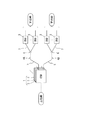
図1は、本発明の実施形態に係るPONシステムの接続形態を示す図である。
図1に示すように、本実施形態のPONシステムは、通信事業者側の光回線終端装置(OLT:Optical Line Terminal )1と、宅側の光回線終端装置(ONU:Optical Network Unit)3とが、ツリー構造のPON回線4A,4Bで接続された接続形態(トポロジ)となっている。
Hereinafter, embodiments of the present invention will be described with reference to the drawings.
[PON system connection form]
FIG. 1 is a diagram showing a connection form of a PON system according to an embodiment of the present invention.
As shown in FIG. 1, the PON system of this embodiment includes an optical line terminal (OLT) 1 on the telecommunications carrier side, an optical network unit (ONU) 3 on the home side, Is a connection form (topology) in which the
事業者側の光回線終端装置1は、複数の光加入者終端盤(OSU:Optical Subscriber Unit )2を1つの筐体に収容した集合体よりなり、この終端盤2にPON回線4A,4Bがそれぞれ接続されている。
以下、本実施形態においては、各々の光加入者終端盤2或いはその集合体である光回線終端装置1を「局側装置」といい、この局側装置にPON回線4A,4Bにて接続された宅側の回線終端装置3を「宅側装置」という。また、「局側装置」を「OSU」又は「OLT」と略記し、「宅側装置」を「ONU」と略記することがある。
The optical
Hereinafter, in this embodiment, each optical
局側装置2には、それぞれ2系統のPON回線4A,4Bが接続されており、これらのPON回線4A,4Bは、局側装置2に繋がる一芯の光ファイバ5と、受動光分岐ノードである光カプラ6と、この光カプラ6から分岐する一芯の光ファイバ7とを有する。
光ファイバ7は、所定の分岐数(例えば、32や64分岐)で光カプラ6から分岐しており、その終端に宅側装置3がそれぞれ接続されている。また、局側装置2の上位側(図1の左側)は上位網に通じており、各宅側装置3の下位側(図1の右側)はそれぞれ下位網に通じている。
Two stations of
The optical fiber 7 is branched from the
PON回線4A,4Bにおける伝送方式としては、上り下りの伝送レートが10G(ボーレートは、10.3125Gbps)の10G−EPON、上り下りの伝送レートが1G(ボーレートは、1.25Gbps)のGE−PON、或いは、下りの伝送レートが10Gでかつ上りの伝送レートが1Gである非対称10G−EPONを採用することができる。
このため、局側装置2は、1Gと10Gの双方の伝送レートに対応しており、宅側装置3は、1GONU、10G非対称ONU、或いは、10G対称ONUよりなる。
As transmission methods in the
For this reason, the station-
〔局側装置の構成〕
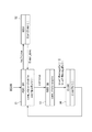
図2は、局側装置2の構成を示すブロック図である。
図2に示すように、局側装置2は、上位側(図2の上側)から下位側に向かって順に、上位スイッチ11、アクセス制御部12A,12B、管理部13、下位スイッチ14、光送受信制御部15及び光送受信部16A,16Bを備えている。
[Configuration of station side equipment]
FIG. 2 is a block diagram showing a configuration of the
As shown in FIG. 2, the
本実施形態の局側装置2は、2系統のPON回線4A,4BをMPCPに則って制御することに対応して、それらのPON回線4A,4Bがそれぞれ接続される2つの光送受信部16A,16Bと、2つのアクセス制御部12A,12Bとを備えている。
なお、以下において、PON回線4A,4Bとアクセス制御部12A,12Bと光送受信部16A,16Bの系統を互いに区別する表現として、「系統A」及び「系統B」を用いることがある。
In response to controlling the two systems of
In the following, “system A” and “system B” may be used as expressions for distinguishing the systems of the
上位スイッチ11は、アクセス制御部12A,12Bの上位側に接続されたL2スイッチよりなる。この上位スイッチ11は、アクセス制御部12A,12Bが送出する上りフレームを多重して上位網に中継し、上位網からPON回線4A,4Bへの下りフレームをユニキャストフレームの場合は分離して、ユニキャストフレームでない場合は必要に応じてコピーして、各々のアクセス制御部12A,12Bに中継する機能を有する。
なお、上位スイッチ11は、上位網からの下りフレームを上位網に折り返したり、アクセス制御部12A,12Bからの上りフレームをアクセス制御部12A,12Bに折り返したりすることも可能である。
The
The
管理部13は、局側装置2の管理と、アクセス制御部12A,12Bを介しての宅側装置3の管理とを行うものであり、管理インタフェース19と縮退制御部(「管理制御部」ともいう。)20とを有している。管理インタフェース19は管理ネットワークに接続されており、このネットワークを介して運用者である通信事業者からの指令を受けることができる。
なお、図2の例では、管理ネットワークが上位網と別のネットワークとなっているが、両者は同一のネットワークであってもよい。
The
In the example of FIG. 2, the management network is a different network from the host network, but both may be the same network.
縮退制御部20は、管理インタフェース19からの入力信号に基づいて、上位スイッチ11の切り替えと、光送受信制御部15を介した下位スイッチ14の切り替えとを行うが、その詳細については後述する。
下位スイッチ14は、アクセス制御部12A,12BのPON側(図2の下側)に接続され、光送受信部16A,16Bの上位側に接続されたL1スイッチよりなる。この下位スイッチ14は、アクセス制御部12A,12Bと光送受信部16A,16Bとの間の電気信号の方路を物理層レベルで切り替える機能を有する。
The
The
〔アクセス制御部と光送受信部の構成〕
本実施形態のアクセス制御部12A,12Bと光送受信部16A,16Bは、いずれも系統Aと系統Bとで同じ構成及び機能を有する。そこで、以下においては、主として、系統Aを例にとってその構成及び機能を説明する。
[Configuration of access controller and optical transceiver]
The
アクセス制御部12Aは、複数のLSIを制御基板に実装して構成された制御装置よりなり、プログラマブルな論理回路(FPGA)やマイクロプロセッサ(MPU)などを有する。アクセス制御部12Aのメモリ等に格納されるコンピュータプログラムには、FPGAの回路設計のためのVHDL及びVerilogなどのハードウェア記述言語や、MPUが行う処理内容を定義するC言語などで記述され、FPGAやMPUなどのデバイスの構造に合わせてコンパイルなどの処理がなされたコードが含まれる。
The
図2に示すように、アクセス制御部12Aは、上位側から下位側に向かって順に、上位側送信部22、上位側受信部23、中継処理部24、LLID管理テーブル25、PON制御部26、PON側受信部27及びPON側送信部28を備えている。
上位スイッチ11から入力された下りフレームは、上位側受信部23により受信されて中継処理部24に送られる。中継処理部24は、その下りフレームをPON側送信部28に送出し、PON側送信部28は、その下りフレームを下位スイッチ14に入力する。
As shown in FIG. 2, the
The downstream frame input from the
下位スイッチ14から入力された上りフレームは、PON側受信部27により受信されて、中継処理部24又はPON制御部26に送られる。
PON側受信部27は、上りフレームがデータフレームである場合は、それを中継処理に24に渡し、MPCPフレームやOAMフレームなどの制御フレームである場合は、それをPON制御部26に渡す。中継処理部24は、そのデータフレームを上位側送信部22に送出し、上位側送信部22は、そのデータフレームを上位スイッチ11に入力する。
The upstream frame input from the
If the upstream frame is a data frame, the PON
PON制御部26は、PON側受信部27から受けた制御フレームの性質に応じた所定の処理を行う。
例えば、PON制御部26は、受信した制御フレームが、自身がPON回線4A,4Bにブロードキャスト送信したディスカバリゲートに応答する、宅側装置3からのレジスタ要求である場合には、その宅側装置3のためのLLIDを決定し、決定したLLIDの値を記したレジスタを生成して、そのレジスタをPON側送信部28に下り送信させる。
The
For example, if the received control frame is a register request from the
また、PON制御部26は、受信した制御フレームが、自身が送信したノーマルゲート(グラント)に対応する、宅側装置3からのレポートである場合には、それに記された送信要求量に応じて、所定のアルゴリズムで上りの動的帯域割当を行う。
そして、PON制御部26は、動的帯域割当の結果決定した送信許可量と、上り送信タイミングを記した所定のLLID宛のグラントを生成し、そのグラントをPON側送信部28に下り送信させる。
In addition, when the received control frame is a report from the
Then, the
PON制御部26は、LLID管理テーブル(以下、単に「管理テーブル」ともいう。)25の管理も行う。この管理テーブル25には、宅側装置を識別するためのLLIDがエントリに含まれる。また、PON制御部26は、LLIDのエントリごとに、論理リンクを維持するのに必要な情報を保持する。この必要情報には、例えば次のものが含まれるが、これらに限られない。
1) PON回線4A,4Bの種別情報
この識別情報は、ONUが系統A又は系統Bのいずれに属するかを示す情報である。
The
1) Type information of the
2)ONUの種別情報
この種別情報は、ONUが1GONU、10G非対称ONU又は10G対称ONUのいずれかを示す情報である。
3)ONUのMACアドレス
4)ONUのRTT情報
2) ONU Type Information This type information is information indicating whether the ONU is a 1GONU, a 10G asymmetric ONU, or a 10G symmetric ONU.
3) ONU MAC address 4) ONU RTT information
5)QoSパラメータ
このパラメータは、当該ONUに設定する優先度クラス、最低保証帯域及び最大許容帯域を定義するためのパラメータである。
6)上位ネットワークにおけるVLANモード
5) QoS parameter This parameter is a parameter for defining a priority class, a minimum guaranteed bandwidth, and a maximum allowable bandwidth set for the ONU.
6) VLAN mode in the upper network
本実施形態では、系統Aと系統Bの各PON制御部26は、中継処理部24、上位側送受信部22,23及び上位スイッチ11を介して、或いは、管理制御部20(縮退制御部でもある。図6及び図7参照)を介したメッセージ通信により互いに通信可能である。
系統AのPON制御部26は、上記通信により、系統BのPON制御部26が使用するLLIDの値と重複しないように自身が使用するLLIDを決定し、系統Aと系統Bの双方で使用するLLIDと、それに対応する上記必要情報を管理テーブル25に保持する。ただし、後述の通り、縮退モードへの移行時にいったん系統Bの論理リンクが切断されるのを許容する実装の場合は、そのような決定は不要である。
In the present embodiment, the
The
また、LLIDを互いに通知し合う方法は、論理リンクが確立又は切断される毎に通知してもよいし、縮退に関する動作モードの切り替え前に纏めて通知してもよい。なお、系統Aと系統BでのLLIDの一意性については、系統Aと系統BのPON制御部26間で互いに通知し合う方法だけでなく、系統Aと系統BのPON制御部26が使用するLLIDの数値範囲を予め分けておく方法で確保することもできる。
すなわち、例えば、系統Aでは奇数を用い、系統Bでは偶数を用いることにしたり、系統Aでは0からインクリメントした値を用い、系統Bでは所定値からデクリメントした値を用いたりしてLLIDの番号空間を分離することにより、系統Aと系統Bとで使用するLLIDの重複を防止できる。
In addition, the method of notifying each other of LLIDs may be notified every time a logical link is established or disconnected, or may be notified collectively before switching the operation mode related to degeneration. The uniqueness of the LLID between the system A and the system B is used not only by the method of notifying each other between the
That is, for example, an odd number is used in the system A, an even number is used in the system B, a value incremented from 0 is used in the system A, and a value decremented from a predetermined value is used in the system B. By separating the two, it is possible to prevent duplication of LLID used in the system A and the system B.
系統A及び系統BのPON制御部26は、局側装置2内に設けられた同じクロック発生器(図示せず。)で動作しており、このクロック発生器でカウントした時刻(タイムスタンプ)についても、上記通信によってお互いに把握している。
系統AのPON制御部26は、系統BのPON制御部26から通知されたタイムスタンプと自身のPONカウンタとを比較する。系統AのPON制御部26は、それらの時刻差が所定値(例えば、128ns)以下であるかを判定し、それを超える場合には、自身のカウンタを系統Bに合わせるか、系統B側でカウンタを合わせるように通知する。
The
The
光送受信部16Aは、周知の光トランシーバよりなり、光受信部30、光送信部31及び合分波部32を内部に有する。光受信部30は、アバランシェフォトダイオード等の受光素子よりなり、光送信部31は、レーザダイオード等の発光素子よりなる。
PON回線4Aからの上り光信号は、合分波部32を通じて光受信部30により受信され、光受信部30は、受信した上り光信号を電気信号に変換して下位スイッチ14に入力する。下位スイッチ14からの下り電気信号は、光送信部31によって光信号に変換され、この下りの光信号は、合分波部32を通じてPON回線4Aに送出される。
The optical transmission /
The upstream optical signal from the PON line 4A is received by the optical receiving
縮退制御部20は、管理ネットワーク経由で受信する運用者からの指令に基づき、スイッチを切り替えるための制御信号を上位スイッチ11と光送受信制御部15に出力する。
光送受信制御部15は、縮退制御部20からの制御信号と、系統Aや系統BのPON制御部26からの制御信号とに基づいて、下位スイッチ14の切り替えと、光送受信部16A,16B内の光受信部30に対する受信制御を行う。この受信制御は、次の上りバースト受信に合わせて、光受信部30の受信態勢(例えば、伝送レートに合わせた受信増幅回路やクロック再生回路、復号回路の選択やリセットなど)を適合させる制御である。
The
Based on the control signal from the
〔縮退制御部によるスイッチ制御〕
図3は、通常モードにおける通信フレームの流れを示す図である。また、図4は、系統A側にアクセス制御を集中させる場合の、縮退モードにおける通信フレームの流れを示す図であり、図5は、系統B側にアクセス制御を集中させる場合の、縮退モードにおける通信フレームの流れを示す図である。
[Switch control by the degeneration control unit]
FIG. 3 is a diagram showing the flow of communication frames in the normal mode. 4 is a diagram showing a flow of communication frames in the degeneration mode when the access control is concentrated on the system A side, and FIG. 5 is a diagram in the degeneration mode when the access control is concentrated on the system B side. It is a figure which shows the flow of a communication frame.
なお、図3〜図5では、上位スイッチ11と上位網との間の接続を示す矢印が一本線で描いてあるが、これは物理的な接続が一本であることを意味するものではない。また、物理的な接続の接続先が一箇所であることを意味するものでもなく、上位スイッチ11から上位網への物理的な接続が複数本あり、接続先が複数の上位装置である場合もある。
以下、図3〜図5を参照して、縮退制御部20が行うスイッチ制御の内容について説明する。
3 to 5, an arrow indicating a connection between the
Hereinafter, the contents of the switch control performed by the
縮退制御部20は、管理インタフェース19から受信する指令が「通常モード」である場合は、両スイッチ11,14の方路を図3のように設定する。この方路の設定を、上りフレームと下りフレームに分けて説明すると、次の通りである。
S1) 上位スイッチ11に入力される系統Aと系統BのPON回線4A,4Bへの下りフレームの出力先を、系統Aと系統Bのアクセス制御部12A,12Bに分散させる。
When the command received from the
S1) The output destination of the downstream frame to the
なお、この場合の出力先は、下りフレームに含まれる情報、例えば、VLAN番号や宛先MACアドレス等に基づいて判定される。系統Aと系統BのPON回線4A,4Bへの下りフレームがユニキャストフレームの場合には、系統Aあるいは系統BのPON回線4A,4Bのいずれかへ転送され、下りフレームがユニキャストフレームでない場合には、PON回線4A,4Bのいずれか片方に転送されるか、あるいは必要に応じて系統Aと系統BのPON回線4A,4Bの両方へ転送される。
Note that the output destination in this case is determined based on information included in the downstream frame, for example, a VLAN number or a destination MAC address. When the downstream frame to the
S2) 系統Aと系統Bのアクセス制御部12A,12Bから下位スイッチ14に入力される下りフレームの出力先を、それぞれ系統A及び系統Bの光送受信部16A,16Bに設定する。
S3) 系統Aと系統Bの光送受信部16A,16Bから下位スイッチ14に入力される上りフレームの出力先を、それぞれ系統A及び系統Bのアクセス制御部12A,12Bに設定する。
S2) The output destinations of the downstream frames input from the
S3) The output destinations of the upstream frames input to the
このように、通常モードでは、同じ系統A,Bのアクセス制御部12A,12Bと光送受信部16A,16Bとが、上り下りの双方に関して1対1対応で接続される。
従って、この通常モードでは、系統Aのアクセス制御部12Aは、自身が通常管理する1つのPON回線4Aに対する上り多重アクセス制御(以下、これを「通常回線制御」という。)を行い、系統Bのアクセス制御部12Bも、同様に、自身が通常管理する1つのPON回線4Bに対する上り多重アクセス制御である通常回線制御を行う。
Thus, in the normal mode, the
Accordingly, in this normal mode, the
縮退制御部20は、管理インタフェース19から受信する指令が、系統A側にアクセス制御を集中させる「縮退モード」である場合は、両スイッチ11,14の方路を図4のように設定する。この方路の設定を、上りフレームと下りフレームに分けて説明すると、次の通りである。
S4) 上位スイッチ11に入力される系統Aと系統BのPON回線4A,4Bへの下りフレームの出力先を、系統Aのアクセス制御部12Aに集中させる。
When the command received from the
S4) The output destinations of the downstream frames to the
S5) 系統Aのアクセス制御部12Aから下位スイッチ14に入力される下りフレームの出力先を、系統A及び系統Bの光送受信部16A,16Bに分散させる。
S6) 系統Aと系統Bの光送受信部16A,16Bから下位スイッチ14に入力される上りフレームの出力先を、下位スイッチ14に対して時分割の多重制御を行って系統Aのアクセス制御部12Aに集中させる。
S5) The output destination of the downstream frame input to the
S6) The output destination of the upstream frame input to the
より具体的には、縮退モードにおいてデータが疎通するアクセス制御部12Aを「アクティブ」、縮退モードにおいてデータが疎通しないアクセス制御部12Bを「スタンバイ」と定義すると、下位スイッチ14は、アクティブなアクセス制御部12AのPON側送信部28から受けた下りフレームをコピーし、それらを各系統A,Bの光送受信部16A,16Bの光送信部31に入力する。
More specifically, when the
また、下位スイッチ14は、各系統A,Bの光送受信部16A,16Bの光受信部30からの上りフレームを、アクティブなアクセス制御部12AのPON側受信部27に対して時分割多重して入力する。
このとき、アクティブなアクセス制御部12AのPON制御部26は、各々のPON回線4A,4Bから光送受信部16A,16Bを経由して受信する上り方向のバースト信号が、下位スイッチ14において欠損しないように、自身が宅側装置3にグラントした送信タイミングに基づいて光送受信制御部15に切り替えタイミングを指示する。
The
At this time, the
このように、図4の縮退モードにおいては、縮退制御部20が上記のように両スイッチ11,14を制御することで、アクティブなアクセス制御部12Aが両系統A,BのPON回線4A,4Bに対する上り多重アクセス制御(以下、これを「複数回線制御」という。)を行うことになる。
また、その結果、スタンバイのアクセス制御部12Bには、両スイッチ11,14から上り及び下りフレームが入力されず、通信フレームが疎通しない非通信状態となる。
As described above, in the degeneration mode of FIG. 4, the
As a result, the standby
また、縮退制御部20は、管理インタフェース19から受信する指令が、系統B側にアクセス制御を集中させる「縮退モード」である場合は、両スイッチ11,14の方路を図5のように設定する。この方路の設定を、上りフレームと下りフレームに分けて説明すると、次の通りである。
S7) 上位スイッチ11に入力される系統Aと系統BのPON回線4A,4Bへの下りフレームの出力先を、系統Bのアクセス制御部12Bに集中させる。
Further, when the command received from the
S7) The downstream frame output destinations to the
S8) 系統Bのアクセス制御部12Bから下位スイッチ14に入力される下りフレームの出力先を、系統A及び系統Bの光送受信部16A,16Bに分散させる。
S9) 系統Aと系統Bの光送受信部16A,16Bから下位スイッチ14に入力される上りフレームの出力先を、下位スイッチ14に対して時分割の多重制御を行って系統Bのアクセス制御部12Bに集中させる。
S8) The output destinations of the downlink frames input from the
S9) The output destination of the upstream frame input to the
従って、図5の縮退モードでは、図4の縮退モードとは逆に、系統Bのアクセス制御部12Bがアクティブとなって、両系統A,BのPON回線4A,4Bに対して複数回線制御を行い、その結果、系統Aのアクセス制御部12Aがスタンバイとなって、通信フレームが疎通しない非通信状態となる。
Therefore, in the degenerate mode of FIG. 5, contrary to the degenerate mode of FIG. 4, the
〔局側装置の運用方法〕
このように、本実施形態では、運用者からの指令に応じて、いずれか一方のアクセス制御部12A,12Bが両系統A,BのPON回線4A,4Bをアクセス制御する複数回線制御を行い、他方のアクセス制御部12A,12Bに通信フレームを疎通させない縮退モードを、局側装置2に実行させることができる。
[Operation method of station side equipment]
As described above, in the present embodiment, in response to a command from the operator, either one of the
従って、例えばPONシステムの運用者は、上記縮退モードの期間中に、スタンバイとなったアクセス制御部12A,12Bに含まれるFPGAやMPUなどのプログラマブルな構成部品に対して、コンピュータプログラムの変更とその変更後の再起動を行うことができる。なお、コンピュータプログラムの「変更」には、当該プログラムの修正、追加及び削除などが含まれる。
Therefore, for example, the operator of the PON system can change the computer program and change the programmable program components such as FPGA and MPU included in the
この場合、縮退モードでは、系統A及び系統BのPON回線4A,4Bについての複数回線制御をアクティブなアクセス制御部12A,12Bが行うので、この縮退モードの期間中に、スタンバイのアクセス制御部12A,12Bに対するコンピュータプログラムの変更と再起動を行うようにすれば、局側装置2でのデータ転送を停止させずに、コンピュータプログラムの更新を行うことができる。
In this case, in the degeneration mode, the active
なお、本実施形態の局側装置2では、スタンバイのアクセス制御部12A,12Bや管理制御部(縮退制御部)20に対するコンピュータプログラムの更新中に、ディスカバリウィンドウの開設やMPCP又はOAMのリンクダウンを禁止する処理が行われるが、この点については後述する。
In the
局側装置2の別の運用方法として、縮退モードの期間中に、スタンバイのアクセス制御12A,12Bへの電力供給を停止又は抑制することにしてもよい。
この場合、系統A,Bのアクセス制御部12A,12Bの双方に通常通り電源供給する場合に比べて、局側装置2のアクセス制御部12A,12Bにおける消費電力を低下させることができる。
As another operation method of the
In this case, the power consumption in the
なお、縮退モードにおいては、アクティブなアクセス制御部12A,12Bが、通常モードの場合よりも多数の宅側装置3に対して上り多重アクセス制御を行うので、通常モードの場合よりも宅側装置3の通信帯域が低下することになる。
このため、縮退モードを行う時間帯は、PON回線4A,4Bにおけるトラフィックが所定値以下となる例えば夜中の時間帯とすることが好ましい。この場合、アクティブなアクセス制御部12A,12Bが制御する宅側装置3が増加することに伴う、宅側装置3あたりの通信帯域の低下の影響を軽減できるようになる。
In the degenerate mode, the active
For this reason, it is preferable that the time zone for performing the degenerate mode is, for example, a time zone during the night when the traffic on the
本実施形態の局側装置2では、上述の通り、アクセス制御部12A,12BのPON制御部26が、両系統A,BでLLIDの値が重複しないように管理し、そのLLIDごとに、論理リンクを維持するのに必要な情報を互いに共有している。
また、アクセス制御部12A,12BのPON制御部26は、上り多重アクセス制御を行うに当たって、同じクロック発生器を用いてクロックの同期を図るとともに、互いのタイムスタンプのずれが所定値以下となるように時刻同期を図っている。
In the
In addition, the
従って、本実施形態の局側装置2では、通常モードから縮退モードへの切り替え、或いは逆に、縮退モードから通常モードへの切り替えを行うことにより、MPCPに基づく上り多重アクセス制御の制御主体が変更されても、両系統A,BのPON回線4A,4Bに属する宅側装置3との論理リンクが維持される。
このため、モードの切り替えごとにLLIDが自動的に切断されることによって、通信が不通となる時間が長くなることを防止できるという利点がある。
Therefore, in the
For this reason, there is an advantage that it is possible to prevent an increase in the time during which communication is interrupted by automatically disconnecting the LLID every time the mode is switched.
〔管理制御部とアクセス制御部の詳細構成〕
図6及び図7は、局側装置(OSU)2の管理部13とアクセス制御部12A,12Bを更に詳細に示すブロック図である。
図6及び図7において、ハッチングを付したブロック部分は、ファームウェアアップデート(Firmware Update :以下、「FU」と略記することがある。)の更新などの、制御機能の停止を伴うコンピュータプログラムの更新中であることを示す。
[Detailed configuration of management control unit and access control unit]
6 and 7 are block diagrams showing the
In FIG. 6 and FIG. 7, the hatched block part is updating a computer program that accompanies a stop of a control function, such as updating a firmware update (hereinafter sometimes abbreviated as “FU”). Indicates that
従って、図6では、縮退モードによってスタンバイとなった系統Bのアクセス制御部12BのPON制御部26にFUを実行している状態を示し、図7では、各系統A,Bのアクセス制御部12A,12Bが通常モードで動作している場合に、管理部13の管理制御部20にFUを実行している状態を示している。
なお、図6に示す縮退モードの期間中に、更に、管理部13の管理制御部20に対してFUが行われる場合もある。
Accordingly, FIG. 6 shows a state in which the FU is executed on the
Note that FU may be further performed on the
図6及び図7に示すように、各系統A,Bのアクセス制御部12A,12Bは、帯域割当部34とリンクダウン制御部35を有する。
帯域割当部34は、PON制御部26の機能のうち、ディスカバリウィンドウを含んだ上り方向の動的帯域割当(Dynamic Bandwidth Allocation:DBA)を担う機能部分であり、通常のDBAサイクルとは別に、所定のディスカバリ周期ごとにディスカバリウィンドウを挿入するかどうかの判定が可能である。一般的に、DBAサイクルは500〜1000μ秒であり、ディスカバリ周期は500ms以上のオーダで実行される。
As shown in FIGS. 6 and 7, the
The
リンクダウン制御部35は、PON制御部26の機能のうち、MPCPリンクとOAMリンクを維持するか否かの判定を担う機能部分であり、LLIDごとにMPCPフレーム又はOAMフレームの受信の有無を確認し、所定のタイムアウト時間が経過しても上りフレームを受信できなかった場合に、当該LLIDの宅側装置3がリンクダウンしたとみなす。なお、IEEE Std 802.3TMでは、そのタイムアウト時間は、MPCPフレームで1秒、OAMフレームで5秒と規定されている。
The link down
管理制御部(縮退制御部)20は、縮退モードのためのスイッチ制御の他に、例えばTCP(Transmission Control Protocol )に基づくメッセージ通信を各系統A,BのPON制御部26と行い、アクセス制御部12A,12Bを管理する機能を有する。
なお、図例では、管理制御部が縮退制御部と同じブロック(CPU)であるが、メッセージ通信による管理を担う管理制御部と、スイッチ制御によるアクセス制御部12A,12Bの動作モードの切り替えを担う縮退制御部を、別のCPUで構成してもよい。
The management control unit (degeneration control unit) 20 performs message communication based on, for example, TCP (Transmission Control Protocol) with the
In the illustrated example, the management control unit is the same block (CPU) as the degeneration control unit, but is responsible for switching the operation mode of the management control unit responsible for message communication and the
管理制御部20は、例えば、新たにリンクアップしたLLIDを記したメッセージをPON制御部26から受信すると、所定のサービスクラスに応じたパラメータ(前記QoSパラメータなど)の値を記したメッセージをPON制御部26に返す。
この場合、PON制御部26は、管理制御部20から通知されたパラメータの値を、前記LLIS管理テーブル25(図2参照)における、リンクアップによって新設したLLIDのエントリの該当欄に保持する。
For example, when the
In this case, the
また、管理制御部20は、リンクダウンしたLLIDを知らせるメッセージをPON制御部26から受信すると、自身が保持するデータベース中のエントリから当該LLIDを削除する。
各系統A,BのPON制御部26と管理制御部20は、それぞれデータベースを保持している。PON制御部26のデータベースには、通常回線制御や複数回線制御に必要となるLLID管理テーブル25が含まれる。
In addition, when the
The
一方、各系統A,Bのアクセス制御部12A,12Bで制御される宅側装置3のリンク状態は、管理制御部20でも把握する必要があるため、管理制御部20のデータベースにもLLID管理テーブル25が含まれる。
従って、管理制御部20がアクセス制御部12A,12Bを正常に管理するためには、管理制御部20と各系統A,BのPON制御部26とで、PON通信に関するデータ内容が一致している必要がある。
On the other hand, since the link state of the
Therefore, in order for the
〔プログラム更新による問題点とその解決法〕
ここで、スタンバイのアクセス制御部12BのPON制御部26がアップデート中である図6の状態において、新たな宅側装置3のリンクアップや既存の宅側装置3のリンクダウンが発生した場合を想定する。
この場合、アクティブなアクセス制御部12Aがその発生を管理制御部20に通知すると、管理制御部20は通知されたLLIDを自身のデータベースに記録又はデータベースから削除する。
[Problems and solutions by program update]
Here, it is assumed that a link up of a new
In this case, when the active
このため、アクティブなアクセス制御部12Aと管理制御部12Aとの間では、共通に保持すべきデータの内容が整合する。
しかし、アップデート中のスタンバイのアクセス制御部12Bには、リンクアップ又はリンクダウンしたLLIDを通知できない。従って、スタンバイのアクセス制御部12Bと管理制御部20が共通に保持すべきデータの内容が整合しなくなり、スタンバイのアクセス制御部12Bが通常回線制御に復帰した場合に、管理制御部20がアクセス制御部12Bを適切に管理できなくなる。
For this reason, the contents of data to be held in common match between the active
However, the standby
また、各系統A,Bのアクセス制御部12A,12Bが通常モードで動作している場合に、管理制御部20に対してFUが行われている図7の状態において、新たな宅側装置3のリンクアップや既存の宅側装置3のリンクダウンが発生した場合を想定する。
この場合、管理制御部20は、自身のFUのために両系統A,BのPON制御部26と通信できないので、アクセス制御部12A,12Bからリンクアップ又はリンクダウンしたLLIDを含むメッセージを受信しても、管理制御部20はそれを受信できない。
Further, when the
In this case, since the
従って、アクセス制御部12A,12Bが、管理制御部20のFU中にリンクアップ又はリンクダウンしたLLIDを記録又は削除すると、アクセス制御部12A,12Bと管理制御部が共通に保持すべきデータの内容が整合しなくなり、FUが終了した後に、管理制御部20がアクセス制御部12A,12Bを適切に管理できなくなる。
なお、管理制御部20のFUに伴う上記問題点は、いずれか一方のアクセス制御部12A,12Bが縮退モードで複数回線制御を行っている場合も同様である。
Therefore, when the
Note that the above problem associated with the FU of the
そこで、本実施形態では、スタンバイのアクセス制御部12B(アクセス制御部12Aでもよい。)や管理制御部20に対するFUの実行中は、宅側装置3のリンク状態の変更を禁止することにより、上記問題点を解決することとした。
すなわち、帯域割当部34によるDBAにおいて、FUの実行中はディスカバリウィンドウを一時的に止めて宅側装置3のリンクアップを禁止することにより、リンクアップイベントが発生しないようにして上述のデータ内容の不整合を防止する。
Therefore, in the present embodiment, during the execution of the FU for the standby
That is, in the DBA by the
また、リンクダウン制御部35によるMPCPリンクダウンとOAMリンクダウンの判定処理において、FUの実行中はその判定を一時的に禁止することにより、リンクダウンイベントが発生しなないようにして上述のデータ内容の不整合を防止する。
なお、かかるリンクアップやリンクダウンの禁止処理は一時的であるから、FUの後に改めて開設されるディスカバリウィンドウによりリンクアップイベントが発生し、FUの後に改めて行われるリンクダウンの判定によりリンクダウンイベントが発生する。
Further, in the MPCP link down and OAM link down determination processing by the link down
Since the link-up / link-down prohibition process is temporary, a link-up event is generated by a discovery window newly opened after the FU, and the link-down event is detected by the link-down determination performed again after the FU. Occur.
このように、本実施形態の帯域割当部34とリンクダウン制御部35は、アクセス制御部12A,12B又は管理制御部20に対するFUの実行中において、宅側装置3のリンク状態の変更を禁止する「変更禁止部」を構成している。
As described above, the
〔第1実施形態〕
図6に示すような、スタンバイのアクセス制御部12BのPON制御部26に対するFUの実行中に、宅側装置3のリンクアップやリンクダウンを禁止するには、アクティブのアクセス制御部12AのPON制御部26が、他方のアクセス制御部12Bに対するFUの実行期間を察知する必要がある。
[First Embodiment]
In order to prohibit link-up and link-down of the
そこで、アクセス制御部12AのPON制御部26は、縮退モードへの移行を指令する管理制御部20からのメッセージの受信を契機に、他方のアクセス制御部12BがFUの状態に入ったとみなして、リンク状態の変更を禁止する指令を生成し、その指令を自身の帯域割当部34とリンクダウン制御部35に送る。
上記指令を受けた帯域割当部34は、DBAにおけるディスカバリウィンドウの開設を停止し、上記指令を受けたリンクダウン制御部35は、MPCP及びOAMリンクダウンの判定を停止する。
Therefore, the
The
その後、アクセス制御部12AのPON制御部26は、通常モードへの移行を指令する管理制御部20からのメッセージの受信を契機に、他方のアクセス制御部12BのFUが終了したとみなして、リンク状態の変更を許容する指令を生成し、その指令を自身の帯域割当部34とリンクダウン制御部35に送る。
上記指令を受けた帯域割当部34は、DBAにおけるディスカバリウィンドウの開設を再開し、上記指令を受けたリンクダウン制御部35は、MPCP及びOAMリンクダウンの判定を再開する。
After that, the
The
なお、前述のように、縮退モードの期間中に、スタンバイのアクセス制御部12Bへの電力供給を停止又は抑制する運用方法もあるので、縮退モードへの移行のメッセージは必ずしもPON制御部26に対するFUの実行であるとは限らない。
そこで、アクティブ側のPON制御部26に宅側装置3のリンク状態の変更を禁止又は解除させるトリガとして、スタンバイ側のPON制御部26に対するFUの開始/終了のメッセージ等の、より明示的なメッセージを採用することにしてもよい。
As described above, there is an operation method in which the power supply to the standby
Therefore, a more explicit message such as a FU start / end message for the standby
以上の通り、本実施形態の局側装置(OSU)2によれば、縮退モードの実行中において、帯域割当部34がディスカバリウィンドウの開設を停止し、リンクダウン制御部35がリンクダウンの判定を停止するので、スタンバイのアクセス制御部12B(具体的にはPON制御部26)に対するFUの実行中に、宅側装置3がリンクアップ又はリンクダウンすることがなく、宅側装置3のリンク状態の変更が発生しない。
従って、スタンバイのアクセス制御部12Bに対するコンピュータプログラムの更新前後で、当該アクセス制御部12Bと管理制御部20が共通に保持すべきデータ内容に不整合が生じるのを未然に防止することができる。
As described above, according to the station side apparatus (OSU) 2 of the present embodiment, the
Therefore, it is possible to prevent inconsistency between data contents that should be held in common by the
〔第2実施形態〕
図7に示すような、管理制御部20に対するFUの実行中に、宅側装置3のリンクアップやリンクダウンを禁止するには、アクセス制御部12A,12BのPON制御部26が、管理制御部20に対するFUの実行期間を察知する必要がある。
[Second Embodiment]
In order to prohibit link-up and link-down of the
そこで、アクセス制御部12A,12BのPON制御部26は、管理制御部20とのメッセージ通信のリンク状態(例えば、TCPのリンク状態)を監視し、そのリンク切れを契機として、管理制御部20がFUの状態に入ったとみなす。
具体的には、アクセス制御部12A,12BのPON制御部26は、ディスカバリの発行又はMPCP/OAMリンクダウンの判定を行う際に、管理制御部20との通信のリンク状態を判定する。
Therefore, the
Specifically, the
その判定の結果、管理制御部20とのリンクが切れている場合には、アクセス制御部12A,12BのPON制御部26は、管理制御部20がFUに入ったとみなし、帯域割当部34にディスカバリウィンドウの開設を停止させ、リンクダウン制御部35にリンクダウンの判定を停止させる。
その後、アクセス制御部12A,12BのPON制御部26は、管理制御部20とのリンクの復帰を定期的に試み、復帰した場合に管理制御部20のFUが完了したとみなし、各部34,35にディスカバリウィンドウの開設とリンクダウンの判定を再開させる。
As a result of the determination, if the link with the
After that, the
(管理制御部のリンク状態の判定処理)
図8〜図10は、管理制御部20に対するFUの実行中における宅側装置3のリンク状態の変更を禁止するため、アクセス制御部12A,12BのPON制御部26、帯域割当部34及びリンクダウン制御部35がそれぞれ実行する処理を示している。
そのうち、図8は、PON制御部26による管理制御部20のリンク状態の判定処理を示す状態遷移図である。図8中の関数等の意味は、それぞれ次の通りである。
(Management control unit link status judgment processing)
8 to 10 show the
8 is a state transition diagram illustrating the link state determination process of the
「comm_state」:PON制御部26と管理制御部20のリンク状態を表す変数である。これが「enable」であればリンクアップを意味し、「disable 」であればリンクダウンを意味する。帯域割当部34やリンクダウン制御部35でも使用される共通変数である。
「OpenPort」 :管理制御部20との通信の「確立」を表す関数である。
「ClearPort 」:管理制御部20との通信の「リセット」を表す関数である。
「MessageTx 」:管理制御部20へのメッセージ送信を表す関数である。
「MessageRx 」:管理制御部20からのメッセージ受信を表す関数である。
「StartTimer」: 管理制御部20に対する接続リトライのためのポーリング用タイマの作動を表す関数である。
“Comm_state”: a variable representing a link state between the
“OpenPort”: a function representing “establishment” of communication with the
“ClearPort”: a function representing “reset” of communication with the
“MessageTx”: a function representing message transmission to the
“MessageRx”: a function representing message reception from the
“StartTimer”: a function representing the operation of a polling timer for retrying connection to the
図8に示すように、状態S1(PORT OFF)は、変数comm_state が「disable」でかつ変数ret が「OpenPort」(メッセージ通信の確立)の状態である。状態S2(HOLD)は、「StartTimer」(タイマ作動)の状態である。
また、状態3(PORT ON )は、変数comm_state が「enable」の状態である。状態S4(CLEAR)は、「ClearPort」(メッセージ通信のリセット)の状態である。
As shown in FIG. 8, the state S1 (PORT OFF) is a state in which the variable comm_state is “disable” and the variable ret is “OpenPort” (establish message communication). The state S2 (HOLD) is a state of “StartTimer” (timer operation).
State 3 (PORT ON) is a state in which the variable comm_state is “enable”. The state S4 (CLEAR) is a state of “ClearPort” (message communication reset).
PON制御部26は、状態S1(PORT OFF)において、変数ret の否定(!)が真である場合(メッセージ通信が確立していない場合)には、状態S2(HOLD)に移行し、ポーリング用タイマを作動させる。
PON制御部26は、状態S2(HOLD)において、「Timer_done」となった場合(ポーリング用タイマが所定時間を経過した場合)には、状態S1(PORT OFF)に戻って同様の処理を繰り返す。
When the negation (!) Of the variable ret is true (when message communication is not established) in the state S1 (PORT OFF), the
In the state S2 (HOLD), the
PON制御部26は、状態S1(PORT OFF)において、変数ret が真である場合(メッセージ通信が確立している場合)には、状態S3(PORT ON)に移行し、変数comm_state を「enable」とする。
PON制御部26は、状態S3(PORT ON )において、「MessageTx 」が真でない或いは「MessageRx 」が真でない場合(管理制御部20とメッセージの送信又は受信ができない場合)には、状態S4(CLEAR)に移行し、管理制御部20とのメッセージ通信をリセットする。
When the variable ret is true in the state S1 (PORT OFF) (when message communication is established), the
When “MessageTx” is not true or “MessageRx” is not true in the state S3 (PORT ON) (when the message cannot be transmitted or received with the management control unit 20), the
なお、PON制御部20は、状態S4(CLEAR)となった場合には、無条件で処理を状態S1(PORT OFF)移行させる。
このように、PON制御部20は、管理制御部20との接続が切れている場合には、一定時間ごとに管理制御部20との接続をリトライし(状態S1と状態S2の往復)、管理制御部20に対するメッセージの送受信が失敗すると、TCPに基づくメッセージ通信のリンクが切断状態(comm_state =「disable」)になったと判定する(状態S3→状態S4→状態S1への移行)。
Note that the
In this way, when the connection with the
(ディスカバリウィンドウの制限を含むDBA)
図9は、帯域割当部34によるディスカバリウィンドウの制限を含むDBAのフローチャートである。帯域割当部34は、DBAサイクルごとに図9の判定フローを実行する。図9中の関数等の意味は、それぞれ次の通りである。
「GrantNormal 」 :通常のDBAサイクルを単位とした帯域割当を表す関数である。
「GrantDiscovery」:ディスカバリウィンドウの開設を表す関数である。
(DBA including discovery window restrictions)
FIG. 9 is a flowchart of DBA including discovery window restriction by the
“GrantNormal”: a function representing bandwidth allocation in units of normal DBA cycles.
“GrantDiscovery”: a function representing the establishment of a discovery window.
「ctime 」 :現在時刻を表す関数である。
「last_disc_time」:最後にディスカバリを開いた時刻を表す変数である。
「disc_thres」 :ディスカバリ周期のパラメータである。
“Ctime”: a function representing the current time.
“Last_disc_time”: a variable representing the time when discovery was last opened.
“Disc_thres”: a parameter of the discovery cycle.
図9に示すように、帯域割当部34は、通常のDBAサイクルを単位とした動的帯域割当を行ったあと(ステップST1)、現在時刻(ctime )から最後にディスカバリを開いた時刻(last_disc_time)を引いた差分がディスカバリ周期(disc_thres)を超えるか否かを判定する(ステップST2)。
帯域割当部34は、その判定結果が「偽(F)」の場合は処理を終了し、その判定結果が「真(T)」の場合は処理を次のステップST3に移行する。
As shown in FIG. 9, the
If the determination result is “false (F)”, the
帯域割当部34は、ステップST3において、PON制御部26が決定する共通変数comm_stateの値を参照し、それが「disable 」の場合(管理制御部20がリンクダウンしている場合)は処理を終了し、それが「enable」の場合(管理制御部20がリンクアップしている場合)に限り、ディスカバリウィンドウを開設する(ステップST4)。
なお、帯域割当部34は、ディスカバリウィンドウを開設した場合には、最後にディスカバリを開いた時刻(last_disc_time)を現在時刻に置き換える(ステップST4)。
In step ST3, the
Note that, when the discovery window is opened, the
(リンクダウン判定の制限)
図10は、リンクダウン制御部35によるリンクダウン判定のフローチャートである。図10中の関数等の意味は、それぞれ次の通りである。
「GetLastRxTime 」:各引数の値に対応する上りフレームの最終受信時刻の取得を指令するコマンドである。引数には「type」と「llid」がある。
「type」:MPCP又はOAMのいずれかを指定する引数である。
「llid」:LLIDの値を指定する引数である。
(Restriction of link down judgment)
FIG. 10 is a flowchart of the link down determination by the link down
“GetLastRxTime”: a command for instructing acquisition of the last reception time of the upstream frame corresponding to the value of each argument. There are "type" and "llid" as arguments.
“Type”: an argument that specifies either MPCP or OAM.
“Llid”: an argument that specifies the value of LLID.
「mpcp_down_thres」:MPCPリンクダウンの判定に用いる閾値である。
「oam_down_thres」:OAMリンクダウンの判定に用いる閾値である。
「MpcpDown」:MPCPリンクをダウンさせて、そのLLIDのエントリのリセットを指令するコマンドである。
「OamDown」:OAMリンクをダウンさせて、OAM状態のリセットを指令するコマンドである。
“Mpcp_down_thres”: a threshold value used for determination of MPCP link down.
“Oam_down_thres”: a threshold used for determination of OAM link down.
“MpcpDown”: A command for instructing to reset the entry of the LLID by bringing down the MPCP link.
“OamDown”: A command for instructing reset of the OAM state by bringing down the OAM link.
図10に示すように、リンクダウン制御部35は、PON制御部26が決定する共通変数comm_stateの値を参照し、それが「disable 」の場合(管理制御部20がリンクダウンしている場合)は処理を終了し、それが「enable」の場合(管理制御部20がリンクアップしている場合)に限り、処理をステップST12に移行する(ステップST11)。
As shown in FIG. 10, the link-down
リンクダウン制御部35は、ステップST12において、現在時刻(ctime )から所定のLLIDの上りフレームの最終受信時刻(GetLastRxTime )を引いた差分が、MPCP用の閾値(mpcp_down_thres )を超えるか否かを判定する。
リンクダウン制御部35は、その判定結果が「偽(F)」の場合は処理をステップST13に移行し、その判定結果が「真(T)」の場合は、MPCPリンクをダウンさせ(ステップST14)、LLIDの値を次の値に置き換える(ステップST16)。
In step ST12, the link-down
If the determination result is “false (F)”, the link-down
リンクダウン制御部35は、ステップST13において、現在時刻(ctime )から所定のLLIDの上りフレームの最終受信時刻(GetLastRxTime )を引いた差分が、OAM用の閾値(oam_down_thres)を超えるか否かを判定する。
リンクダウン制御部35は、その判定結果が「偽(F)」の場合は、OAMのリンクダウンを行わずにLLIDの値を次の値に置き換え(ステップST16)、その判定結果が「真(T)」の場合は、OAMリンクをダウンさせてから(ステップST15)、LLIDの値を次の値に置き換える(ステップST16)。
In step ST13, the link-down
If the determination result is “false (F)”, the link-down
リンクダウン制御部35は、ステップST17において、LLIDの値が最後であるか否かを判定し、その判定結果が「真(T)」の場合は処理を終了し、その判定結果が「偽(F)」の場合は、処理をステップST12の前に戻す。
なお、図10の例では、1回の処理でMPCPとOAMの双方のリンクダウンを行うか否かを判定する場合を例示したが、それらのリンクダウンを個別に判定することにしてもよい。
In step ST17, the link-down
In the example of FIG. 10, the case where it is determined whether or not the MPCP and the OAM link down are performed in one process is illustrated, but the link down may be individually determined.
以上の通り、本実施形態の局側装置(OSU)2によれば、管理制御部20とアクセス制御部12A,12BのPON制御部26との通信が不通である間は、帯域割当部34がディスカバリウィンドウの開設を停止し、リンクダウン制御部35がリンクダウンの判定を停止するので、管理制御部20に対するFUの実行中に、宅側装置3がリンクアップ又はリンクダウンすることがなく、宅側装置3のリンク状態の変更が発生しない。
従って、管理制御部20に対するコンピュータプログラムの更新前後で、アクセス制御部12A,12Bと管理制御部20が共通に保持すべきデータ内容に不整合が生じるのを未然に防止することができる。
As described above, according to the station side unit (OSU) 2 of the present embodiment, while the communication between the
Therefore, it is possible to prevent inconsistency in data contents that the
〔第1の変形例〕
上述の実施形態において、縮退制御部20が両スイッチ11,14の方路を切り替えることによる局側装置2の動作モードの切り替えにより、論理リンクが自動的に切断されるのを許容する実装としてもよい。
もっとも、かかる実装の場合には、各々の系統A,Bのアクセス制御部12A,12BのPON制御部26は、縮退制御部20が両スイッチ11,14の切り替えを行う前後で上り多重アクセス制御の制御主体が変わるLLIDの登録を、解除することが好ましい。
[First Modification]
In the above-described embodiment, the
However, in such an implementation, the
例えば、局側装置2の動作モードを、通常モードから、系統Aがアクティブとなり系統Bがスタンバイとなる縮退モードに切り替える場合には、系統Bのアクセス制御部12BのPON制御部26は、PON回線4Bに属する宅側装置3からデレジスタ要求を受信したか否かに関係なく、一律に、PON回線4Bに属するすべての宅側装置3に対してデレジスタを送信するようにすればよい。
For example, when the operation mode of the
このようにすれば、局側装置2の動作モードが縮退モードに切り替わった後に、PON回線4Bに属する宅側装置3がアクセス制御部12AのPON制御部26にレジスタ要求を行い、この要求を契機として、アクセス制御部12AのPON制御部26が、PON回線4Bに属する宅側装置3に対して新たにLLIDを割り当てるので、局側装置2の動作モードを縮退モードに切り替える前に、各々の系統A,BのPON制御部26が使用するLLIDの値を重複しないように管理する必要がなくなる。
従って、比較的簡単に縮退モードを実現することができる。
In this way, after the operation mode of the
Therefore, the degenerate mode can be realized relatively easily.
〔第2の変形例〕
上述の実施形態において、アクティブなアクセス制御部12A,12Bによる宅側装置3の登録方法として、複数回線制御の実行期間中においては、下位スイッチ14における上りフレームの入力元を、ディスカバリプロセスごとに系統A又は系統Bの光送受信部16A,16Bのいずれかに固定し、その固定状態で宅側装置3の登録シーケンスを実行することが好ましい。
[Second Modification]
In the above-described embodiment, as a registration method of the
その理由は、次の通りである。すなわち、宅側装置3の登録シーケンスは、次の制御フレームを局側装置2と宅側装置3とがやり取りする手順で行われる。
1)局側装置2がディスカバリゲートをブロードキャストする。
2)宅側装置3がレジスタ要求を局側装置2に返す。
3)局側装置2がLLIDを記したレジスタを宅側装置3に送信する。
4)宅側装置3がレジスタ確認を局側装置2に返す。
The reason is as follows. That is, the registration sequence of the
1) The
2) The
3) The
4) The
従って、例えば、系統Aのアクセス制御部12AのPON制御部26が上記登録シーケンスの主体である場合に、その登録シーケンスの途中で、下位スイッチ14における上りフレームの入力元が切り替わると、宅側装置3からの応答(レジスタ要求やレジスタ確認)を当該アクセス制御部12AのPON制御部26が受信できなくなり、宅側装置3の登録シーケンスを適切に実行できなくなる。
Therefore, for example, when the
この点、ディスカバリプロセスごとに光送受信部16A,16Bを固定して登録シーケンスを実行すれば、その登録シーケンスの手順を同じアクセス制御部12A,12Bが適切に実行することができ、アクティブなアクセス制御部12A,12Bが複数回線制御を行っている期間中でも、新たな宅側装置3を適切にPONに加入させることができる。
また、この場合、アクティブなアクセス制御部12A,12Bは、新たな宅側装置3がA,Bいずれの系統のPONに属するかを確実に把握することができる。
In this regard, if the optical transmission /
Further, in this case, the active
〔第3の変形例〕
上述の実施形態において、各系統A,Bのアクセス制御部12A,12Bは、MPCPに従う上り多重アクセス制御において、許可する上りフレームの送信タイミングが、縮退制御部20による両スイッチ11,14の切り替え前であるグラントのみを生成することが好ましい。
[Third Modification]
In the above-described embodiment, the
より具体的には、グラントの生成時点をt1、スイッチ11,14の切り替え時点をt2、グラントに記す上りフレームの送信タイミングをt3とし、系統A側にアクセス制御を集中させるようにスイッチ11,14を切り替える場合を想定すると、縮退モードにおいてスタンバイとなるアクセス制御部12BのPON制御部26は、t1<t2<t3となるタイミングの場合には、グラントを生成せず、t1<t3<t2となるタイミングの場合に限り、グラントを生成するようにする。
More specifically, it is assumed that the grant generation time is t1, the switching time of the
その理由は、t1<t2<t3となるタイミングで、縮退モードにおいてスタンバイとなるアクセス制御部12BのPON制御部26がグラントを生成すると、このPON制御部26がスイッチ11,14の切り替え前に許可したグラントに基づく上りフレームが、スイッチ11,14の切り替え後に局側装置2に到達し、アクティブなアクセス制御部12AのPON制御部26が過去にグラントした他の上りフレームと衝突する可能性があるからである。
The reason for this is that when the
この点、縮退モードにおいてスタンバイとなるアクセス制御部12BのPON制御部26が、t1<t3<t2となるタイミングのみでグラントを生成すれば、縮退モードへの切り替えに伴う上記のような上り送信の衝突を未然に回避することができ、縮退モードへの移行を適切に行うことができる。
In this regard, if the
〔第4の変形例〕
上述の実施形態では、OLT1を構成するOSU2がそれぞれ上位スイッチ11を有する場合を例示したが、上位スイッチ11は、例えば図11に示すように、各OSU2の上位側を多重する冗長化した集線盤11aにより構成することにしてもよい。
この場合、上位スイッチ11のすべての機能を集線盤11aに行わせるようにすれば、OSU2の実装基板に上位スイッチ11が不要となる。もっとも、上位スイッチ11の機能を集線盤11aとOSU2の実装基板に分担させてもよい。
[Fourth Modification]
In the above-described embodiment, the case where the
In this case, if all the functions of the
〔その他の変形例〕
今回開示した実施形態(上述の各変形例を含む。)はすべての点で例示であって制限的なものではない。本発明の権利範囲は、上述の実施形態ではなく、特許請求の範囲に記載した構成と均等の範囲内でのすべての変更が含まれる。
例えば、上述の実施形態では、双方の系統A,Bのアクセス制御部12A,12Bが、複数回線制御を実行可能となっているが、例えば、一方のアクセス制御部12Aのみが複数回線制御を実行でき、他方のアクセス制御部12Bは通常回線制御のみを実行するものであってもよい。
[Other variations]
The embodiment disclosed this time (including the above-described modifications) is illustrative in all respects and not restrictive. The scope of the right of the present invention is not the embodiment described above, but includes all modifications within the scope equivalent to the configurations described in the claims.
For example, in the above-described embodiment, the
上述の実施形態では、局側装置2に2系統のPON回線4A,4Bが接続され、アクセス制御部12A,12Bと光送受信部16A,16Bが、2つの系統A,Bに対応してそれぞれ1対設けられているが、これらは3系統以上あってもよい。
例えば、3系統(系統A〜C)のPON回線4A〜4Cを有する局側装置2の場合は、系統Cの光送受信部16Cを系統A,Bのアクセス制御部12B,12Cに分散して帰属させ、アクセス制御部12Cを非通信状態とする縮退構成や、系統B,Cの光送受信部16B,16Cを系統Aのアクセス制御部12Aに帰属させ、アクセス制御部12B,12Cを同時に非通信状態とする縮退構成など、種々の縮退構成を定義できる。
In the above-described embodiment, two systems of
For example, in the case of the
このように、3系統以上のPON回線4A〜4Cを制御する局側装置2を想定すると、縮退モードの場合にアクティブとなる、「第1」のPON回線、アクセス制御部及び光送受信部は、複数存在することがあり得る。
また、同様に、縮退モードの場合にスタンバイとなる、「第2」のPON回線、アクセス制御部及び光送受信部についても、複数存在することがあり得る。
As described above, assuming the station-
Similarly, there may be a plurality of “second” PON lines, access control units, and optical transmission / reception units that are in standby in the degenerate mode.
上述の実施形態(各変形例を含む。)に係る局側装置2において、切り替え可能な動作モードとしては、「縮退モード」と「通常モード」の2種類だけでなく、その他の1又は複数の動作モード(例えば、「強制停止モード」)が含まれていてもよい。
In the station-
1 局側装置(OLT)
2 局側装置(OSU)
3 宅側装置(ONU)
4A PON回線
4B PON回線
11 上位スイッチ
12A アクセス制御部
12B アクセス制御部
14 下位スイッチ
15 光送受信制御部
16A 光送受信部
16B 光送受信部
19 管理インタフェース
20 管理制御部(縮退制御部)
25 LLID管理テーブル
26 PON制御部
34 帯域割当部(変更禁止部)
35 リンクダウン制御部(変更禁止部)
1 Station side equipment (OLT)
2 Station side equipment (OSU)
3. Home unit (ONU)
25 LLID management table 26 PON control unit
34 Bandwidth allocation unit (change prohibition unit)
35 Link-down control part (change prohibition part)
Claims (11)
複数のPON回線に対応して設けられたアクセス制御部と、
複数の前記アクセス制御部とそれぞれ通信して当該アクセス制御部を管理し、少なくとも1つの前記アクセス制御部に対して下記に定義する通常モードと縮退モードを含む動作モードを指示可能な管理制御部と、
前記縮退モードの実行中は前記宅側装置のリンク状態の変更を禁止する変更禁止部と、を備えていることを特徴とする局側装置。
通常モード:各々のアクセス制御部が、自身が通常管理するPON回線の上り多重アクセス制御である通常回線制御を行う動作モード
縮退モード:特定のアクセス制御部が、自身が通常管理するPON回線と他のPON回線の上り多重アクセス制御である複数回線制御を行い、他のPON回線に対応する他のアクセス制御部に通信フレームを疎通させない動作モード A station side device that constitutes a PON system with a plurality of home side devices,
An access control unit provided corresponding to a plurality of PON lines;
A management control unit capable of communicating with each of the plurality of access control units to manage the access control unit, and instructing at least one of the access control units to specify an operation mode including a normal mode and a degenerate mode as described below; ,
A station-side apparatus, comprising: a change prohibiting unit that prohibits a change in a link state of the home-side apparatus during execution of the degenerate mode.
Normal mode: An operation mode in which each access control unit performs normal line control that is uplink multiple access control of the PON line that is normally managed. Degenerate mode: PON line that the specific access control part normally manages and others Mode that performs multiple line control, which is uplink multiple access control for PON lines, and does not allow communication frames to communicate with other access control units corresponding to other PON lines
複数のPON回線に対応して設けられたアクセス制御部と、
複数の前記アクセス制御部とそれぞれ通信して当該アクセス制御部を管理し、少なくとも1つの前記アクセス制御部に対して下記に定義する通常モードと縮退モードを含む動作モードを指示可能な管理制御部と、
前記管理制御部と前記アクセス制御部との通信が不通である間は前記宅側装置のリンク状態の変更を禁止する変更禁止部と、を備えていることを特徴とする局側装置。
通常モード:各々のアクセス制御部が、自身が通常管理するPON回線の上り多重アクセス制御である通常回線制御を行う動作モード
縮退モード:特定のアクセス制御部が、自身が通常管理するPON回線と他のPON回線の上り多重アクセス制御である複数回線制御を行い、他のPON回線に対応する他のアクセス制御部に通信フレームを疎通させない動作モード A station side device that constitutes a PON system with a plurality of home side devices,
An access control unit provided corresponding to a plurality of PON lines;
A management control unit capable of communicating with each of the plurality of access control units to manage the access control unit, and instructing at least one of the access control units to specify an operation mode including a normal mode and a degenerate mode as described below; ,
A station-side device, comprising: a change prohibiting unit that prohibits a change in a link state of the home-side device while communication between the management control unit and the access control unit is interrupted.
Normal mode: An operation mode in which each access control unit performs normal line control that is uplink multiple access control of the PON line that is normally managed. Degenerate mode: PON line that the specific access control part normally manages and others Mode that performs multiple line control, which is uplink multiple access control for PON lines, and does not allow communication frames to communicate with other access control units corresponding to other PON lines
通常モード:各々のアクセス制御部が、自身が通常管理するPON回線の上り多重アクセス制御である通常回線制御を行う動作モード
縮退モード:特定のアクセス制御部が、自身が通常管理するPON回線と他のPON回線の上り多重アクセス制御である複数回線制御を行い、他のPON回線に対応する他のアクセス制御部に通信フレームを疎通させない動作モード A method of switching and operating an operation mode of a station side apparatus to which at least two PON lines are connected, and includes a normal mode and a degeneration mode defined below as switchable operation modes. The operation method of the station-side apparatus is characterized in that the access control unit prohibits the change of the link state of the home-side apparatus during execution of.
Normal mode: An operation mode in which each access control unit performs normal line control that is uplink multiple access control of the PON line that is normally managed. Degenerate mode: PON line that the specific access control part normally manages and others Mode that performs multiple line control, which is uplink multiple access control for PON lines, and does not allow communication frames to communicate with other access control units corresponding to other PON lines
通常モード:各々のアクセス制御部が、自身が通常管理するPON回線の上り多重アクセス制御である通常回線制御を行う動作モード
縮退モード:特定のアクセス制御部が、自身が通常管理するPON回線と他のPON回線の上り多重アクセス制御である複数回線制御を行い、他のPON回線に対応する他のアクセス制御部に通信フレームを疎通させない動作モード A method of switching and operating an operation mode of a station side apparatus to which at least two PON lines are connected, and includes a normal mode and a degeneration mode defined below as switchable operation modes, and an access control unit A method for operating a station-side device, wherein the access control unit prohibits a change in the link state of the home-side device while communication between the management control unit that manages the access control unit and the access control unit is interrupted.
Normal mode: An operation mode in which each access control unit performs normal line control that is uplink multiple access control of the PON line that is normally managed. Degenerate mode: PON line that the specific access control part normally manages and others Mode that performs multiple line control, which is uplink multiple access control for PON lines, and does not allow communication frames to communicate with other access control units corresponding to other PON lines
下記に定義する通常モードと縮退モードを含む動作モードで前記上り多重アクセス制御を行うPON制御部と、
前記縮退モードの実行中は前記宅側装置のリンク状態の変更を禁止する変更禁止部と、を備えていることを特徴とするアクセス制御装置。
通常モード:当該アクセス制御装置と他のアクセス制御装置が、自身が通常管理するPON回線の上り多重アクセス制御である通常回線制御を行う動作モード
縮退モード:当該アクセス制御装置が、自身が通常管理するPON回線と他のPON回線の上り多重アクセス制御である複数回線制御を行い、他のPON回線に対応する他のアクセス制御部に通信フレームを疎通させない動作モード An access control apparatus that performs uplink multiple access control,
A PON control unit that performs the uplink multiple access control in an operation mode including a normal mode and a degenerate mode defined below;
An access control apparatus comprising: a change prohibiting unit that prohibits a change in the link state of the home side apparatus during execution of the degenerate mode.
Normal mode: Operation mode in which the access control device and other access control devices perform normal line control, which is uplink multiple access control of the PON line that they normally manage. Degenerate mode: The access control device normally manages itself. An operation mode in which multiple line control, which is uplink multiple access control for PON lines and other PON lines, is performed and communication frames are not communicated to other access control units corresponding to other PON lines.
下記に定義する通常モードと縮退モードを含む動作モードで前記上り多重アクセス制御を行うPON制御部と、
自身を管理する管理制御部と通信できない間は前記宅側装置のリンク状態の変更を禁止する変更禁止部と、を備えていることを特徴とするアクセス制御装置。
通常モード:当該アクセス制御装置と他のアクセス制御装置が、自身が通常管理するPON回線の上り多重アクセス制御である通常回線制御を行う動作モード
縮退モード:当該アクセス制御装置が、自身が通常管理するPON回線と他のPON回線の上り多重アクセス制御である複数回線制御を行い、他のPON回線に対応する他のアクセス制御装置に通信フレームを疎通させない動作モード An access control apparatus that performs uplink multiple access control,
A PON control unit that performs the uplink multiple access control in an operation mode including a normal mode and a degenerate mode defined below;
An access control device comprising: a change prohibiting unit that prohibits a change in the link state of the home side device while it cannot communicate with the management control unit that manages itself.
Normal mode: Operation mode in which the access control device and other access control devices perform normal line control, which is uplink multiple access control of the PON line that they normally manage. Degenerate mode: The access control device normally manages itself. An operation mode in which multiple line control, which is uplink multiple access control for PON lines and other PON lines, is performed and communication frames are not communicated to other access control devices corresponding to other PON lines.
請求項7又は8に記載の運用方法が可能な前記局側装置と、
を備えていることを特徴とするPONシステム。 A plurality of home-side devices respectively connected to the plurality of PON lines;
The station side apparatus capable of the operation method according to claim 7 or 8,
PON system characterized by comprising.
Priority Applications (1)
| Application Number | Priority Date | Filing Date | Title |
|---|---|---|---|
| JP2012074478A JP2013207555A (en) | 2012-03-28 | 2012-03-28 | Pon system, station side device and operation method therefor, and access control device |
Applications Claiming Priority (1)
| Application Number | Priority Date | Filing Date | Title |
|---|---|---|---|
| JP2012074478A JP2013207555A (en) | 2012-03-28 | 2012-03-28 | Pon system, station side device and operation method therefor, and access control device |
Publications (1)
| Publication Number | Publication Date |
|---|---|
| JP2013207555A true JP2013207555A (en) | 2013-10-07 |
Family
ID=49526239
Family Applications (1)
| Application Number | Title | Priority Date | Filing Date |
|---|---|---|---|
| JP2012074478A Pending JP2013207555A (en) | 2012-03-28 | 2012-03-28 | Pon system, station side device and operation method therefor, and access control device |
Country Status (1)
| Country | Link |
|---|---|
| JP (1) | JP2013207555A (en) |
Cited By (3)
| Publication number | Priority date | Publication date | Assignee | Title |
|---|---|---|---|---|
| JP2014230022A (en) * | 2013-05-21 | 2014-12-08 | 三菱電機株式会社 | Station-side device |
| JP2016146561A (en) * | 2015-02-09 | 2016-08-12 | 三菱電機株式会社 | Station side device, communication system, and state monitoring method |
| JP2018129006A (en) * | 2017-02-10 | 2018-08-16 | 日本電信電話株式会社 | Communication device, component switching method, and computer program |
-
2012
- 2012-03-28 JP JP2012074478A patent/JP2013207555A/en active Pending
Cited By (3)
| Publication number | Priority date | Publication date | Assignee | Title |
|---|---|---|---|---|
| JP2014230022A (en) * | 2013-05-21 | 2014-12-08 | 三菱電機株式会社 | Station-side device |
| JP2016146561A (en) * | 2015-02-09 | 2016-08-12 | 三菱電機株式会社 | Station side device, communication system, and state monitoring method |
| JP2018129006A (en) * | 2017-02-10 | 2018-08-16 | 日本電信電話株式会社 | Communication device, component switching method, and computer program |
Similar Documents
| Publication | Publication Date | Title |
|---|---|---|
| US9350480B2 (en) | Relay device, relay method, and optical communication system which uses relay device | |
| KR101286011B1 (en) | Communication method, optical communication system, user-side optical-line terminal apparatus, station-side optical-line terminal apparatus, and control apparatus | |
| EP2164189B1 (en) | Passive optical network system and fault determination method | |
| CA3044720C (en) | Passive optical network system, optical line terminal, and optical network unit | |
| US9680575B2 (en) | Relay device, station side device, and communication system and communication method using relay device | |
| JP5541249B2 (en) | PON system, station side apparatus, operation method thereof, and access control apparatus | |
| JP2007049376A (en) | Optical subscriber line terminal station, optical subscriber line terminating device, and down band control method | |
| JP2013207555A (en) | Pon system, station side device and operation method therefor, and access control device | |
| WO2012136089A1 (en) | Loop detection method and system for passive optical network | |
| JP2014049775A (en) | Optical communication system, master station device, path switching control device, and communication control method | |
| JP6028395B2 (en) | Power saving control system, master station device, and power saving control program | |
| JP5456131B2 (en) | Communication method, optical communication system, user side optical line terminator, station side optical line terminator | |
| JP5907208B2 (en) | PON system and station side device | |
| JP2013187759A (en) | Station-side device, pon system and band allocating method | |
| WO2013186900A1 (en) | Optical transmission system, station-side optical terminal apparatus, and communication line switching method | |
| CN110121124B (en) | PON aggregation remote DCN ring prevention method | |
| JP2014168290A5 (en) | ||
| JP5730443B2 (en) | Optical transmission system, station side optical termination device, and communication line switching method | |
| KR102211854B1 (en) | Apparatus for Passive Optical Networks and system having the same | |
| JP2016025575A (en) | Optical line terminal, optical network unit, pon system, and optical communication method | |
| CN113395614A (en) | Passive optical network system and data transmission method | |
| JP2015005862A (en) | Optical signal relay device, station side device, optical communication system, and communication control method |