JP2013202702A - Power tool - Google Patents
Power tool Download PDFInfo
- Publication number
- JP2013202702A JP2013202702A JP2012071292A JP2012071292A JP2013202702A JP 2013202702 A JP2013202702 A JP 2013202702A JP 2012071292 A JP2012071292 A JP 2012071292A JP 2012071292 A JP2012071292 A JP 2012071292A JP 2013202702 A JP2013202702 A JP 2013202702A
- Authority
- JP
- Japan
- Prior art keywords
- switch
- housing
- motor
- pressure switch
- control component
- Prior art date
- Legal status (The legal status is an assumption and is not a legal conclusion. Google has not performed a legal analysis and makes no representation as to the accuracy of the status listed.)
- Pending
Links
Images


Classifications
-
- B—PERFORMING OPERATIONS; TRANSPORTING
- B25—HAND TOOLS; PORTABLE POWER-DRIVEN TOOLS; MANIPULATORS
- B25F—COMBINATION OR MULTI-PURPOSE TOOLS NOT OTHERWISE PROVIDED FOR; DETAILS OR COMPONENTS OF PORTABLE POWER-DRIVEN TOOLS NOT PARTICULARLY RELATED TO THE OPERATIONS PERFORMED AND NOT OTHERWISE PROVIDED FOR
- B25F5/00—Details or components of portable power-driven tools not particularly related to the operations performed and not otherwise provided for
- B25F5/001—Gearings, speed selectors, clutches or the like specially adapted for rotary tools
-
- B—PERFORMING OPERATIONS; TRANSPORTING
- B25—HAND TOOLS; PORTABLE POWER-DRIVEN TOOLS; MANIPULATORS
- B25F—COMBINATION OR MULTI-PURPOSE TOOLS NOT OTHERWISE PROVIDED FOR; DETAILS OR COMPONENTS OF PORTABLE POWER-DRIVEN TOOLS NOT PARTICULARLY RELATED TO THE OPERATIONS PERFORMED AND NOT OTHERWISE PROVIDED FOR
- B25F5/00—Details or components of portable power-driven tools not particularly related to the operations performed and not otherwise provided for
- B25F5/008—Cooling means
Abstract
Description
本発明は、回転軸を有する電動機と、電動機を収容するハウジングとを備えた電動工具に関する。 The present invention relates to an electric tool including an electric motor having a rotating shaft and a housing that houses the electric motor.
従来、可搬型の電動工具としては、例えば、インパクトドライバやドライバドリル,ディスクグラインダ等の電動工具があり、これらは何れも回転軸を有する電動機と、電動機を収容するハウジング本体と、ハウジング本体に一体に設けられて作業者により把持されるグリップとを備えている。電動機としては、消耗部品であるブラシを備えないブラシレスDCモータが多く採用され、これにより小型軽量化を図りつつメンテナンス性を向上させ、さらにはトルク特性(制御性能)に優れた電動工具を実現している。つまり、ブラシレスDCモータを採用し、複数のFET(電界効果トランジスタ)等を備えたインバータ回路で複数のコイル(U相,V相,W相)に大きな駆動電流を順次流すことで、小型でありながらより強い力で木材等の被加工対象物にネジやボルト等を締め付けることが可能な電動工具を実現できる。 Conventionally, as portable electric tools, for example, there are electric tools such as an impact driver, a driver drill, and a disc grinder, all of which are integrated with an electric motor having a rotating shaft, a housing main body that accommodates the electric motor, and the housing main body. And a grip that is gripped by an operator. As a motor, many brushless DC motors that do not have consumable brushes are used, which improves the maintainability while reducing the size and weight, and realizes an electric tool with excellent torque characteristics (control performance). ing. In other words, a brushless DC motor is adopted, and a large drive current is sequentially passed through a plurality of coils (U phase, V phase, W phase) in an inverter circuit having a plurality of FETs (field effect transistors) and the like, thereby reducing the size. However, it is possible to realize an electric tool that can tighten a screw, a bolt, or the like on a workpiece such as wood with a stronger force.
このような電動工具としては、例えば、特許文献1に記載された電動工具が知られている。特許文献1に記載された電動工具は、ハンマおよびアンビルを備えたインパクト工具であり、当該インパクト工具は、胴体部(ハウジング本体),グリップ部(グリップ)およびバッテリ保持部よりなるハウジングを備えている。胴体部には、回転軸を有するブラシレスDCモータ(電動機)が収容され、グリップ部には、トリガ操作部を有するトリガスイッチが収容され、グリップ部のさらにバッテリ保持部寄りには、トリガ操作部の操作に伴いブラシレスDCモータの速度を制御する制御回路基板(制御部品)が設けられている。この制御回路基板は、バッテリパック(二次電池)の略真上に横たわるよう当該バッテリパックに近接して配置されている。
As such a power tool, for example, a power tool described in
ところで、可搬型の電動工具においては、操作性の向上はもちろん、さらなる小型軽量化および長寿命化が望まれている。しかしながら、上述の特許文献1に記載された電動工具によれば、電動機を回転駆動するために作業者により操作されるスイッチとして、トリガ操作部を有するトリガスイッチを採用している。このトリガスイッチは、トリガ操作部の後方に、比較的ストロークの長いスライド式接点(スライドスイッチ)を備え、さらには引き操作されたトリガ操作部を元の位置に戻すバネ部材(戻しバネ)を備えている。したがって、多量のネジを締め付ける場合等においては、作業者はバネ部材の反力に抗して、長いストロークのトリガ操作部を何度も引き操作しなければならず、必ずしも操作性が良いと言えるものでは無かった。また、トリガスイッチは、スライド式接点およびバネ部材を備えるために大型であり、グリップ内でのトリガスイッチの占める容積、つまりトリガスイッチの収容スペースが大きくなり、これが電動工具をより小型軽量化する際の障害となっていた。さらに、制御部品は二次電池に近接して配置されているため、制御部品および二次電池の放熱性が低下し、ひいては電動工具の寿命が低下するという問題も生じ得る。
By the way, in a portable electric tool, not only improvement in operability but also further reduction in size and weight and longer life are desired. However, according to the electric power tool described in
本発明の目的は、操作性の向上はもちろん、さらなる小型軽量化および長寿命化を図ることが可能な電動工具を提供することにある。 An object of the present invention is to provide an electric tool capable of further reducing the size and weight and extending the life as well as improving the operability.
本発明の電動工具は、回転軸を有する電動機と、前記電動機を収容するハウジングとを備えた電動工具であって、前記ハウジングに設けられるスイッチ収容部および制御部品収容部と、前記スイッチ収容部に収容され、作業者の押圧操作により電気信号を発生する圧力スイッチと、前記圧力スイッチを被覆し、前記作業者の押圧操作により弾性変形する操作カバーと、前記制御部品収容部に収容され、前記圧力スイッチからの前記電気信号の大きさに応じて前記電動機の回転状態を制御する制御部品と、を有することを特徴とする。 The electric tool of the present invention is an electric tool including an electric motor having a rotating shaft and a housing that accommodates the electric motor, wherein the switch accommodating portion and the control component accommodating portion provided in the housing, and the switch accommodating portion. A pressure switch that is housed and generates an electrical signal by a pressing operation of an operator; an operation cover that covers the pressure switch and is elastically deformed by the pressing operation of the worker; And a control component that controls the rotation state of the electric motor according to the magnitude of the electric signal from the switch.
本発明の電動工具は、前記ハウジングに、前記電動機の回転状態を表示する表示部を設けることを特徴とする。 The electric power tool of the present invention is characterized in that a display portion for displaying a rotation state of the electric motor is provided in the housing.
本発明の電動工具は、前記ハウジング内に、前記制御部品収容部を横切るように空気が流通する空気通路を設けることを特徴とする。 The electric power tool of the present invention is characterized in that an air passage through which air flows is provided in the housing so as to cross the control component housing portion.
本発明の電動工具は、前記ハウジングに、前記スイッチ収容部を密閉するように前記操作カバーを設けることを特徴とする。 The electric power tool of the present invention is characterized in that the operation cover is provided in the housing so as to seal the switch housing portion.
本発明の電動工具によれば、ハウジングにスイッチ収容部および制御部品収容部を設け、スイッチ収容部には、作業者の押圧操作により電気信号を発生する圧力スイッチを収容し、圧力スイッチを被覆し、作業者の押圧操作により弾性変形する操作カバーを設け、制御部品収容部には、圧力スイッチからの電気信号の大きさに応じて電動機の回転状態を制御する制御部品を収容する。 According to the electric tool of the present invention, the housing is provided with the switch accommodating portion and the control component accommodating portion, and the switch accommodating portion accommodates the pressure switch that generates the electric signal by the pressing operation of the operator and covers the pressure switch. An operation cover that is elastically deformed by a pressing operation of the operator is provided, and a control component that controls the rotation state of the electric motor according to the magnitude of the electric signal from the pressure switch is accommodated in the control component accommodating portion.
このように、圧力スイッチを用いることで操作方向に沿う厚み寸法を、従前のトリガスイッチの操作方向に沿う厚み寸法に比して小さくすることができ、ひいては電動工具のさらなる小型軽量化を実現できる。また、例えば、圧力スイッチと制御部品とをハウジング内で近接させて配置できるようになり、制御部品を二次電池等の発熱部材から遠ざけて、ひいては電動工具の長寿命化を図ることができる。 Thus, the thickness dimension along the operation direction can be reduced by using the pressure switch as compared with the thickness dimension along the operation direction of the conventional trigger switch, and further reduction in size and weight of the electric tool can be realized. . Further, for example, the pressure switch and the control component can be arranged close to each other in the housing, and the control component can be moved away from the heat generating member such as a secondary battery, thereby extending the life of the electric tool.
さらに、圧力スイッチの操作量(押圧量)は、従前のトリガスイッチの操作量(スライド量)に比して少なくて済むので、電動工具の操作性を向上させることができる。また、操作カバーを設けるので、圧力スイッチの操作時において、操作の感触を和らげて操作性をより向上させつつ、圧力スイッチを衝撃等から保護して電動工具の長寿命化を図ることができる。この場合、ハウジングに、スイッチ収容部を密閉するように操作カバーを設ければ、ハウジング内への雨水や埃等の進入を確実に防止して制御部品等を保護することができる。 Furthermore, since the operation amount (pressing amount) of the pressure switch is smaller than the operation amount (sliding amount) of the conventional trigger switch, the operability of the electric tool can be improved. In addition, since the operation cover is provided, it is possible to extend the life of the electric tool by protecting the pressure switch from impacts and the like while reducing the operation feeling and improving the operability when operating the pressure switch. In this case, if an operation cover is provided in the housing so as to seal the switch accommodating portion, it is possible to reliably prevent rainwater, dust and the like from entering the housing and protect the control components and the like.
また、ハウジングに、電動機の回転状態を表示する表示部を設けることで、作業者は電動機の回転状態を一目で把握できるようになり、ひいては電動工具の操作性をさらに向上させることができる。さらに、ハウジング内に、制御部品収容部を横切るように空気が流通する空気通路を設けることで、制御部品の冷却効率を高めることが可能となる。 Further, by providing the housing with a display unit that displays the rotation state of the electric motor, the operator can grasp the rotation state of the electric motor at a glance, and thus the operability of the electric tool can be further improved. Furthermore, it is possible to increase the cooling efficiency of the control component by providing an air passage through which air flows so as to cross the control component housing portion in the housing.
以下、本発明の一実施の形態について、図面を用いて詳細に説明する。 Hereinafter, an embodiment of the present invention will be described in detail with reference to the drawings.
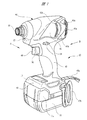
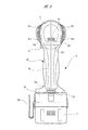
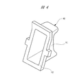
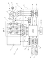
図1は本発明に係るインパクトドライバを示す斜視図を、図2は図1の矢印A方向から見たインパクトドライバの部分断面図を、図3は図1のB矢視図を、図4はスイッチユニットを覆うスイッチカバーを示す斜視図を、図5はインパクトドライバの電気系統を示すブロック図をそれぞれ表している。 1 is a perspective view showing an impact driver according to the present invention, FIG. 2 is a partial cross-sectional view of the impact driver as seen from the direction of arrow A in FIG. 1, FIG. 3 is a view taken in the direction of arrow B in FIG. FIG. 5 is a perspective view showing a switch cover covering the switch unit, and FIG. 5 is a block diagram showing an electric system of the impact driver.
図1,2に示すように、電動工具としてのインパクトドライバ10は、充電可能なバッテリ(二次電池)11を備え、当該バッテリ11を電源としてモータ(電動機)20は駆動されるようになっている。モータ20は回転打撃機構30を駆動し、当該回転打撃機構30は出力軸であるアンビル35に回転と打撃を与え、これによりドライバビット等の先端工具(図示せず)に連続する回転力や断続的な打撃力を伝達するようになっている。このようにしてインパクトドライバ10は、強い力でネジ締めやボルト締め等の作業を行えるようになっている。
As shown in FIGS. 1 and 2, an
インパクトドライバ10は、その外郭をなすハウジング40を備えている。ハウジング40は、プラスチック等の樹脂材料を射出成形することにより、側面から見た形状が略T字形状となるように形成されている。ハウジング40は、モータ20の回転軸21を挟む左右側(図2の手前側および奥側)で分割されるようになっており、これらを組み付けた状態のもとでハウジング40の内部は空洞となっている。ハウジング40は、回転軸21の軸方向に沿って延びるハウジング本体41と、回転軸21の軸方向と略直交する方向に延びるグリップ42と、グリップ42を挟んでハウジング本体41と対向するように設けられたバッテリ保持部43とを備え、これらは一体に設けられている。
The
ハウジング本体41の内部には、図2に示すように、ブラシレスDCモータよりなるモータ20と、回転打撃機構30を収容するハンマケース12とが収容されている。ハンマケース12は回転軸21の軸方向に沿う一方側(図中右側の前方)に配置され、モータ20は回転軸21の軸方向に沿う他方側(図中左側の後方)に配置されている。つまり、モータ20とハンマケース12とは、回転軸21を中心として同軸上に配置されている。
As shown in FIG. 2, the
モータ20は、環状に形成されたステータ(固定子)22と、円筒状に形成されたロータ(回転子)23とを備えている。ステータ22には複数のコイル24が所定の巻き方で巻装されており、当該ステータ22はハウジング本体41に固定されている。一方、ロータ23は周方向に沿って複数着磁された永久磁石によって形成され、当該ロータ23はステータ22の径方向内側に微少隙間(エアギャップ)を介して回転自在に設けられている。これにより、各コイル24に駆動電流を順次供給することでロータ23が所定の回転速度で回転するようになっている。
The
ロータ23の回転中心には、回転軸21が貫通して固定され、当該回転軸21の軸方向に沿う一方側および他方側は、それぞれハウジング本体41に固定された一対のベアリング13によってそれぞれ回転自在に支持されている。これにより、ロータ23は、ステータ22に対して接触すること無くスムーズに回転するようになっている。
A
回転軸21の軸方向一方側で、ロータ23とベアリング13との間には、冷却ファン14が固定されている。冷却ファン14は、プラスチック等の樹脂材料よりなり、回転軸21の回転に伴って回転するようになっている。これにより、ハウジング40の内部に外気(空気)を導入して、モータ20および制御回路基板70等の発熱部品を冷却するようにしている。
A cooling
ハウジング本体41の後方側には、図1,3に示すように、ハウジング本体41内に外気を導入するための複数の第1外気導入孔41aが設けられている。また、グリップ42の後方側には、図2,3に示すように、グリップ42内に外気を導入するための複数の第2外気導入孔42aが設けられている。さらに、ハウジング本体41の長手方向に沿う略中央部分には、図1に示すように、ハウジング40の内部、つまりハウジング本体41およびグリップ42内に導入した外気をハウジング40の外部に排出するための複数の外気排出孔41bが設けられている。
As shown in FIGS. 1 and 3, a plurality of first outside air introduction holes 41 a for introducing outside air into the
図2に示すように、ハンマケース12に収容された回転打撃機構30は、遊星歯車機構31,スピンドル32およびハンマ33を備えている。遊星歯車機構31は、回転軸21とスピンドル32との間に設けられ、回転軸21の回転を減速して高トルク化し、当該高トルク化された回転力をスピンドル32に伝達するようになっている。また、スピンドル32とハンマ33との間にはカム機構34が設けられ、当該カム機構34は、スピンドル32の外周面に形成された略V字形状のスピンドルカム溝34a,ハンマ33の内周面に形成されたハンマカム溝34bおよび各カム溝34a,34bにそれぞれ係合するスチールボール(鋼球)34cによって形成されている。
As shown in FIG. 2, the
ハンマ33の前方側には、先端工具が装着されるアンビル35が設けられており、当該アンビル35のハンマ33側(後方側)およびハンマ33のアンビル35側(前方側)には、それぞれ互いに係合または係合解除可能な凸部(図示せず)が対向するよう形成されている。また、遊星歯車機構31とハンマ33との間にはコイルスプリング36が設けられ、ハンマ33はコイルスプリング36によって常に前方側、つまりアンビル35側に付勢されている。
On the front side of the
ここで、回転打撃機構30の動作を説明すると、回転軸21の非回転時、つまりインパクトドライバ10の停止時においては、スチールボール34cと各カム溝34a,34bとの係合により、アンビル35およびハンマ33の各凸部は互いに係合可能な状態となっている。そして、当該状態のもとで回転軸21が回転駆動されると、これに伴い遊星歯車機構31を介してスピンドル32が回転し、当該スピンドル32の回転力はカム機構34を介してハンマ33に伝達される。これにより、ハンマ33およびアンビル35の各凸部が係合してアンビル35が回転駆動される。
Here, the operation of the
その後、先端工具の回転トルクが大きくなる等してアンビル35が回転し難くなると、このときの各凸部の係合反力が大きくなり、スピンドル32とハンマ33との間に相対回転が生じ、これによりスチールボール34cと各カム溝34a,34bとの係合が解かれて、ハンマ33はコイルスプリング36を圧縮しつつモータ20側に後退するようになる。そして、ハンマ33が後退することにより、ハンマ33およびアンビル35の各凸部が互いに相手を乗り越えてその係合が解除される。
Thereafter, when the
このときのハンマ33には、スピンドル32の回転力およびコイルスプリング36の弾性力が負荷されており、これによりハンマ33は回転しつつアンビル35に向かう方向に急加速される。その後、ハンマ33の凸部とアンビル35の凸部とが再び勢い良く係合するようになり、このときの強力な回転打撃力がアンビル35、つまり先端工具に伝達される。それ以降は、ハンマ33およびアンビル35の各凸部の係合解除と衝撃的な係合とが繰り返されることにより、先端工具を介してネジ等に回転打撃力を間欠的に伝達することができ、ひいてはネジ等を木材などの被締結部材(ワーク)に確実にねじ込めるようになっている。
At this time, the
ハウジング本体41の内部で、モータ20およびハンマケース12のグリップ42寄りには、LEDライト15と表示パネル(表示部)16とが設けられている。LEDライト15は、ハウジング本体41のハンマケース12側、つまり先端工具が取り付けられる前方側に配置され、バッテリ保持部43に設けられたライトスイッチ17(図1参照)をオン操作することにより、先端工具の周辺(作業部分周辺)を照らせるようになっている。これにより、暗闇でのネジ締め等の作業性を向上させている。
An
一方、表示パネル16は、ハウジング本体41のモータ20側、つまり先端工具が取り付けられる前方側とは反対の後方側に配置され、作業者により容易に目視できるようになっている。表示パネル16は、図3に示すように3つの発光素子(LED)16a,16b,16cを備え、これらの発光素子16a〜16cは、回転軸21の回転速度が速くなるにつれて徐々に点灯数が増えるようになっている。つまり、当該表示パネル16は、モータ20の回転状態を表示するものであって、具体的な表示動作については後述する。ただし、表示パネル16は、ハウジング本体41の後方側に設けるに限らず、グリップ42の長手方向に沿う上方側あるいは下方側で、かつ回転軸21の軸方向に沿う後方側に設けるようにしても良い。
On the other hand, the
グリップ42は、ハウジング本体41に一体に設けられ、作業者により把持されるようになっている。グリップ42の内部には、図2に示すように、スイッチ収容部42bと制御部品収容部42cとが互いに近接して設けられている。スイッチ収容部42bは、グリップ42の回転軸21の軸方向に沿う一方側(前方側)でかつハウジング本体41側に設けられ、制御部品収容部42cは、グリップ42の回転軸21の軸方向に沿う他方側(後方側)に設けられている。
The
スイッチ収容部42bと制御部品収容部42cとの間には、グリップ42の長手方向(図中上下方向)に延びるようにして仕切壁42dが設けられ、当該仕切壁42dは、グリップ42の内部を、スイッチ収容部42b側と制御部品収容部42c側とに仕切るようになっている。これにより、冷却ファン14の回転によって各第2外気導入孔42aから制御部品収容部42c内に導入された外気が、グリップ42の長手方向に沿ってバッテリ保持部43側からハウジング本体41側に向けて流通するようになっている(図7参照)。つまり、仕切壁42dの制御部品収容部42c側には、グリップ42の長手方向に沿う一方側(下方側)から他方側(上方側)に向けて延び、制御部品収容部42cを横切る空気通路42eが設けられている。
A
スイッチ収容部42bには、スイッチユニット50が収容されている。当該スイッチユニット50は、平板状の圧電素子(ピエゾ素子)よりなる圧力スイッチ51と、当該圧力スイッチ51からの電圧信号(電気信号)を増幅する増幅部材(増幅回路)52とを備えている。圧力スイッチ51の前方側は、その操作性を向上させるために、グリップ42の前方側にグリップ42から突出され、これにより作業者はグリップ42を把持することで、人差し指等で容易に圧力スイッチ51を押圧操作できるようになっている。
A
ここで、圧力スイッチ51は、その厚み方向に加えられた作業者からの押圧力により、当該押圧力の大きさに比例した大きさの電圧信号を発生するようになっている。また、圧力スイッチ51に対する押圧力を開放、つまり圧力スイッチ51から人差し指等を離して開放操作することにより、電圧信号の発生が停止されるようになっている。ただし、平板状の圧電素子に代えて平板状のひずみゲージを用いることもでき、この場合、ひずみゲージの抵抗値の変化を電気信号として扱うようにする。
Here, the
このように平板状の圧力スイッチ51を用いることで、スイッチユニット50のグリップ42内への突出量を減らして、ひいてはスイッチ収容部42bの大きさを従前のトリガスイッチの場合に比して小さくできるようにしている。これにより、スイッチユニット50の後方側に比較的大きなスペースを確保して、当該部分に仕切壁42d,制御部品収容部42cおよび空気通路42eを形成できるようにしている。
By using the
ここで、図1に示すように、グリップ42の長手方向に沿うハウジング本体41寄りには、スイッチユニット50に近接して正逆切替レバー18が設けられている。当該正逆切替レバー18は作業者により親指等でオンオフ操作されるようになっており、正逆切替レバー18をオン操作またはオフ操作することにより、回転軸21の回転方向を正回転または逆回転に切り替えられるようになっている。
Here, as shown in FIG. 1, the forward /
スイッチユニット50のグリップ42から突出した部分、つまり圧力スイッチ51の前方側は、操作カバーとしてのスイッチカバー60によって被覆されている。スイッチカバー60は、図4に示すように、例えばエチレンプロピレンゴム(EPDM)等の柔軟性に優れた弾性材料によって形成され、これによりスイッチカバー60は、作業者の押圧操作により弾性変形するようになっている。スイッチカバー60は、略箱形状に形成されており、スイッチユニット50の圧力スイッチ51側を被覆する有底の本体部61と、本体部61における開口側の全周に亘って一体に設けられ、分割可能なハウジング40により挟持されるフランジ部62とを備えている。
A portion protruding from the
そして、フランジ部62はハウジング40に設けた装着凹部(図示せず)に入り込んでハウジング40により挟持され、これによりグリップ42のスイッチ収容部42bを密閉するようになっている。スイッチカバー60とハウジング40との接触部分はラビリンス構造(詳細図示せず)となっており、このラビリンス構造によりハウジング40内への雨水や埃等の進入を確実に防止して、スイッチユニット50等のハウジング40内に設けられる構成部品の長寿命化を図れるようにしている。また、スイッチカバー60を設けることで圧力スイッチ51を保護できるとともに、圧力スイッチ51の操作の感触を和らげてソフトタッチで操作できるようにし、さらには押圧操作時に滑るようなことも防止でき、ひいては圧力スイッチ51の操作性をより向上させている。
The
図2に示すように、制御部品収容部42cには、制御部品としての制御回路基板70が収容されており、当該制御回路基板70は、圧力スイッチ51からの電圧信号の大きさに応じてモータ20の回転状態を制御するようになっている。制御回路基板70は、グリップ42の長手方向に沿うよう縦置き状態で設けられ、これにより空気通路42eを閉塞しないようにして外気の流通の妨げにならないようにしている。このように、制御回路基板70をグリップ42におけるスイッチユニット50の後方側に配置してバッテリ11から遠ざけているので、バッテリ11の熱が制御回路基板70に、また制御回路基板70の熱がバッテリ11に伝達され難くなっている。これにより、インパクトドライバ10の長寿命化を図っている。
As shown in FIG. 2, a
また、制御回路基板70を、従前のようにバッテリ11の略真上に横たわるように配置しなくて済むので、バッテリ保持部43およびバッテリ11を含む高さ寸法hを、従前に比して詰められるようにしている。したがって、バッテリ保持部43およびバッテリ11を含む高さ寸法hを詰められる分、インパクトドライバ10の全体の高さ寸法Hを詰めることができ、ひいてはインパクトドライバ10の小型化を可能としている。
Further, since the
バッテリ保持部43は、バッテリ11を保持するようになっている。バッテリ11には、図1,2に示すようにリリースボタン11aが設けられ、当該リリースボタン11aを把持しつつバッテリ11をバッテリ保持部43に対して前方側へスライドさせることで、バッテリ11をバッテリ保持部43から取り外せるようになっている。また、バッテリ保持部43の後方側にはハンドストラップ43aが取り付けられ、バッテリ保持部43の左側(図1中手前側)には金属製のベルト掛け43bが取り付けられている。なお、ベルト掛け43bはバッテリ保持部43に対して着脱自在となっており、バッテリ保持部43の右側(図1中奥側)にも取り付けられるようになっている。
The
図5に示すように、制御回路基板70は、複数のスイッチング素子(FET)Q1〜Q6を有するインバータ部71と、演算部72aやその他複数の電気回路を有する制御部72とを備えている。そして、制御回路基板70には、モータ20の各コイル24(U相,V相,W相),圧力スイッチ51(増幅部材52),正逆切替レバー18,各発光素子16a〜16c,バッテリ11,温度センサ73および3つの回転子位置検出素子(ホール素子)74a〜74cが電気的に接続されている。
As shown in FIG. 5, the
モータ20は、インナーロータ型のブラシレスDCモータであって、複数組のN極およびS極を含むロータ23と、スター結線したU相,V相,W相(3相)からなるコイル24が巻装されたステータ22と、ロータ23の回転位置を検出するために、ステータ22の周方向に所定間隔(例えば60°間隔)で配置された3つの回転子位置検出素子74a〜74cと、各コイル24の近傍に設けられてモータ20の温度を検出する温度センサ73とを備えている。
The
温度センサ73からの検出信号は、制御部72の温度上昇測定回路72bに入力され、温度上昇測定回路72bからは、モータ20(各コイル24)の温度データとして演算部72aに出力されるようになっている。これにより演算部72aは、モータ20が異常に高温となるような場合、つまり焼き付きが起こるような場合に、モータ20を非常停止(フェイルセーフ動作)させるようにする。
The detection signal from the
各回転子位置検出素子74a〜74cからの検出信号は、制御部72の回転子位置検出回路72cに入力され、回転子位置検出回路72cからは、ロータ23の回転位置データとして演算部72aに出力されるようになっている。また、各回転子位置検出素子74a〜74cからの検出信号は、回転子位置検出回路72cを介して回転数検出回路72dに入力され、回転数検出回路72dからは、ロータ23の回転数データとして演算部72aに出力されるようになっている。これにより演算部72aでは、現在のモータ20の回転状態(回転位置や回転数)を把握して、これに基づいてその後のモータ20の回転状態を制御するようになっている。
Detection signals from the rotor
制御部72には、インバータ部71に流れる電流値を検出する電流検出回路72eが設けられ、これによりモータ20に供給されている現在の電流値が演算部72aにフィードバックされるようになっている。そして、演算部72aは、モータ20に対する負荷が大きくなる等して、モータ20に過電流が流れていることを検知すると、モータ20を非常停止(フェイルセーフ動作)するよう制御信号出力回路72hを制御するようになっている。
The
圧力スイッチ51(増幅部材52)からの電圧信号は、制御部72の印加電圧設定回路72fに入力され、印加電圧設定回路72fは、圧力スイッチ51からの電圧信号を調整して操作量データとし、当該操作量データを演算部72aに出力するようになっている。つまり、作業者により圧力スイッチ51が弱い力で押圧操作された場合には、演算部72aに出力される操作量データは小さくなり、作業者により圧力スイッチ51が強い力で押圧操作された場合には、演算部72aに出力される操作量データは大きくなる。
The voltage signal from the pressure switch 51 (amplifying member 52) is input to the applied
正逆切替レバー18からの切替信号は、制御部72の回転方向設定回路72gに入力され、回転方向設定回路72gからは、正回転データまたは逆回転データとして演算部72aに出力されるようになっている。これらの正回転データまたは逆回転データに基づいて、演算部72aはロータ23を正方向または逆方向に回転駆動するようになっている。
The switching signal from the forward /
インバータ部71は、3相のブリッジ形式に電気的に接続された6つのスイッチング素子Q1〜Q6を備え、各スイッチング素子Q1〜Q6の各ゲートは、制御部72の制御信号出力回路72hにそれぞれ電気的に接続されている。また、各スイッチング素子Q1〜Q6の各ドレインまたは各ソースは、U相,V相,W相の各コイル24にそれぞれ電気的に接続されている。これにより、各スイッチング素子Q1〜Q6は、制御信号出力回路72hからのスイッチング素子駆動信号H1〜H6により、それぞれスイッチング動作を行い、インバータ部71に印加されるバッテリ11の直流電圧を3相の電圧Vu,Vv,Vwとして各コイル24にそれぞれ電力を供給するようになっている。
The
各スイッチング素子Q1〜Q6の各ゲートを駆動する各スイッチング素子駆動信号H1〜H6のうち、3つの負電源側の各スイッチング素子Q4〜Q6をそれぞれパルス幅変調信号(PWM信号)H4〜H6として供給するようになっている。これにより、制御部72の演算部72aによって、圧力スイッチ51の操作量(押圧量)に応じた操作量データに基づいてPWM信号のパルス幅(デューティ比)を変化させ、モータ20への電力供給量を調整し、モータ20の駆動および停止と回転速度とを制御するようにしている。
Of the switching element drive signals H1 to H6 for driving the gates of the switching elements Q1 to Q6, the three switching elements Q4 to Q6 on the negative power supply side are supplied as pulse width modulation signals (PWM signals) H4 to H6, respectively. It is supposed to be. Accordingly, the
ここで、PWM信号は、インバータ部71の正電源側の各スイッチング素子Q1〜Q3または負電源側の各スイッチング素子Q4〜Q6の何れか一方に供給され、各スイッチング素子Q1〜Q3または各スイッチング素子Q4〜Q6を高速でスイッチング動作させることでバッテリ11の直流電圧から各電圧Vu,Vv,Vwを制御するようにしている。なお、本実施の形態においては、負電源側の各スイッチング素子Q4〜Q6にPWM信号が供給されるため、PWM信号のパルス幅を制御することによって各コイル24に供給する電力を調整してモータ20の回転速度を制御することができる。
Here, the PWM signal is supplied to any one of the switching elements Q1 to Q3 on the positive power supply side or the switching elements Q4 to Q6 on the negative power supply side of the
次に、以上のように形成されたインパクトドライバ10の動作について、図面を用いて詳細に説明する。図6は圧力スイッチ引き荷重とモータ回転数との関係を示す特性図を、図7はハウジング内を流通する空気の流路を説明する説明図をそれぞれ表している。
Next, the operation of the
作業者によりグリップ42を把持し、当該状態のもとで圧力スイッチ51を押圧操作すると、モータ20の各コイル24に電力(駆動電流)が供給されて、ロータ23(回転軸21)が所定の回転数で回転駆動される。これにより、遊星歯車機構31,スピンドル32,カム機構34およびハンマ33を介して、アンビル35が回転駆動される。これにより、先端工具を介してネジには回転打撃力が与えられて、ひいてはネジを木材に確実にねじ込むことができる。
When the operator grips the
このとき、図6に示すように、作業者による圧力スイッチ51の押圧力(押圧量)が比較的小さい領域の「F1(N)未満」のときには、モータ20の回転数は「1000rpm未満」となり、さらに表示パネル16の各発光素子16a〜16cは1個点灯した状態、つまり発光素子16aのみが点灯した状態(低速回転表示)となる。
At this time, as shown in FIG. 6, when the pressing force (pressing amount) of the
また、作業者による圧力スイッチ51の押圧力が中程度の領域の「F1(N)以上F2(N)未満」のときには、モータ20の回転数は「1000rpm以上2000rpm未満」となり、さらに表示パネル16の各発光素子16a〜16cは2個点灯した状態、つまり2つの発光素子16a,16bが点灯した状態となる(中速回転表示)。
Further, when the pressing force of the
さらに、作業者による圧力スイッチ51の押圧力が大きい領域の「F2(N)以上」のときには、モータ20の回転数は「2000rpm以上」となり、さらに表示パネル16の各発光素子16a〜16cは3個全てが点灯した状態となる(高速回転表示)。
Further, when the pressure of the
ここで、圧力スイッチ51は、従前のトリガスイッチに比して操作量が少なく、作業者の感触による圧力スイッチ51の操作量の把握が難しい場合がある。これを補うために本実施の形態では、作業者によって目視し易い位置に表示パネル16を設け、これにより圧力スイッチ51であっても、インパクトドライバ10の充分な操作性を確保できるようにしている。また、図6に示す特性は、演算部72aによって任意に制御することができ、例えば、圧力スイッチ51を操作する操作力が小さい作業者向けの場合には、図6の特性よりも急に変化する特性(変化の割合大)とし、圧力スイッチ51を操作する操作力が大きい作業者向けの場合には、図6の特性よりも緩く変化する特性(変化の割合小)とすれば良い。
Here, the
インパクトドライバ10の作業中においては、図7に示すように回転軸21の回転に伴って冷却ファン14が回転するようになっている。これにより、各第1外気導入孔41a(図1,3参照)からハウジング本体41内に外気が導入され、その後、ハウジング本体41内に導入された外気は、図中二点鎖線矢印CMに示すようにモータ20を通過して、モータ20を冷却する。そして、モータ20を通過した外気は、各外気排出孔41b(図1参照)を介してハウジング本体41の外部に排気される。
During the operation of the
また、各第2外気導入孔42a(図2,3参照)からグリップ42内にも外気が導入され、その後、グリップ42内に導入された外気は、図中二点鎖線矢印CCに示すように空気通路42eの途中にある制御回路基板70を通過して、制御回路基板70の表面および裏面に実装された電子部品(スイッチング素子Q1〜Q6等)を冷却する。そして、制御回路基板70を通過した外気は、各外気排出孔41bを介してハウジング本体41の外部に排気される。
In addition, outside air is also introduced into the
以上詳述したように、本実施の形態に係るインパクトドライバ10によれば、ハウジング40にスイッチ収容部42bおよび制御部品収容部42cを設け、スイッチ収容部42bには、作業者の押圧操作により電気信号を発生する圧力スイッチ51を備えたスイッチユニット50を収容し、圧力スイッチ51を被覆しかつスイッチ収容部42bを密閉するように、作業者の押圧操作により弾性変形するスイッチカバー60を設け、制御部品収容部42cには、圧力スイッチ51からの電気信号の大きさに応じてモータ20の回転状態を制御する制御回路基板70を収容した。
As described above in detail, according to the
このように、圧力スイッチ51を用いることで操作方向に沿う厚み寸法を、従前のトリガスイッチの操作方向に沿う厚み寸法に比して小さくすることができ、ひいてはインパクトドライバ10のさらなる小型軽量化を実現できる。また、圧力スイッチ51と制御回路基板70とをハウジング40内で近接させて配置したので、制御回路基板70をバッテリ11等の発熱部材から遠ざけて、ひいてはインパクトドライバ10の長寿命化を図ることができる。
Thus, by using the
さらに、圧力スイッチ51の操作量(押圧量)は、従前のトリガスイッチの操作量(スライド量)に比して少なくて済むので、インパクトドライバ10の操作性を向上させることができる。また、スイッチカバー60を設けたので、圧力スイッチ51の操作時において、操作の感触を和らげて操作性をより向上させることができる。さらに、スイッチカバー60を設けたので、圧力スイッチ51を衝撃等から保護しつつ、ハウジング40内への雨水や埃等の進入を防止して制御回路基板70を保護し、ひいてはインパクトドライバ10の長寿命化を図ることができる。
Further, since the operation amount (pressing amount) of the
また、ハウジング40に、モータ20の回転状態を表示する表示パネル16を設けたので、作業者はモータ20の回転状態を一目で把握することができ、ひいてはインパクトドライバ10の操作性をさらに向上させることができる。また、ハウジング40内に、制御部品収容部42cを横切るように空気が流通する空気通路42eを設けたので、制御回路基板70の冷却効率を高めることができる。
Further, since the
本発明は上記実施の形態に限定されるものではなく、その要旨を逸脱しない範囲で種々変更可能であることは言うまでもない。上記実施の形態においては、電動工具としてインパクトドライバ10であるものを示したが、本発明はこれに限らず、回転軸を有する電動機と、電動機を収容するハウジングとを備えた他の電動工具、例えば、ドライバドリルやディスクグラインダ等の電動工具にも適用することができる。
It goes without saying that the present invention is not limited to the above-described embodiment, and various modifications can be made without departing from the scope of the invention. In the above embodiment, the
また、上記実施の形態においては、ハウジング40を形成するグリップ42の内部に、その長手方向に沿うよう仕切壁42dを設けたものを示したが、本発明はこれに限らず、仕切壁42dを省略してグリップ42内の全域に外気を流通させるようにしても良い。
Moreover, in the said embodiment, although what provided the
さらに、上記実施の形態においては、表示部として3つの発光素子16a〜16cを有する表示パネル16としたものを示したが、本発明はこれに限らず、例えば、モータ20の回転数をデジタル表示する液晶表示パネルとしても良い。
Further, in the above embodiment, the
10…インパクトドライバ(電動工具)、11…バッテリ、11a…リリースボタン、12…ハンマケース、13…ベアリング、14…冷却ファン、15…LEDライト、16…表示パネル(表示部)、16a〜16c…発光素子、17…ライトスイッチ、18…正逆切替レバー、20…モータ(電動機)、21…回転軸、22…ステータ、23…ロータ、24…コイル、30…回転打撃機構、31…遊星歯車機構、32…スピンドル、33…ハンマ、34…カム機構、34a…スピンドルカム溝、34b…ハンマカム溝、34c…スチールボール、35…アンビル、36…コイルスプリング、40…ハウジング、41…ハウジング本体、41a…第1外気導入孔、41b…外気排出孔、42…グリップ、42a…第2外気導入孔、42b…スイッチ収容部、42c…制御部品収容部、42d…仕切壁、42e…空気通路、43…バッテリ保持部、43a…ハンドストラップ、43b…ベルト掛け、50…スイッチユニット、51…圧力スイッチ、52…増幅部材、60…スイッチカバー(操作カバー)、61…本体部、62…フランジ部、70…制御回路基板(制御部品)、71…インバータ部、72…制御部、72a…演算部、72b…温度上昇測定回路、72c…回転子位置検出回路、72d…回転数検出回路、72e…電流検出回路、72f…印加電圧設定回路、72g…回転方向設定回路、72h…制御信号出力回路、73…温度センサ、74a〜74c…回転子位置検出素子、Q1〜Q6…スイッチング素子
DESCRIPTION OF
Claims (4)
前記ハウジングに設けられるスイッチ収容部および制御部品収容部と、
前記スイッチ収容部に収容され、作業者の押圧操作により電気信号を発生する圧力スイッチと、
前記圧力スイッチを被覆し、前記作業者の押圧操作により弾性変形する操作カバーと、
前記制御部品収容部に収容され、前記圧力スイッチからの前記電気信号の大きさに応じて前記電動機の回転状態を制御する制御部品と、
を有することを特徴とする電動工具。 An electric tool comprising an electric motor having a rotating shaft and a housing for accommodating the electric motor,
A switch housing portion and a control component housing portion provided in the housing;
A pressure switch that is housed in the switch housing portion and generates an electrical signal by a pressing operation of an operator;
An operation cover that covers the pressure switch and is elastically deformed by a pressing operation of the operator;
A control component that is housed in the control component housing portion and controls the rotation state of the electric motor according to the magnitude of the electrical signal from the pressure switch;
A power tool characterized by comprising:
Priority Applications (3)
| Application Number | Priority Date | Filing Date | Title |
|---|---|---|---|
| JP2012071292A JP2013202702A (en) | 2012-03-27 | 2012-03-27 | Power tool |
| CN2013100508014A CN103358266A (en) | 2012-03-27 | 2013-02-08 | Power tool |
| US13/769,178 US20130255981A1 (en) | 2012-03-27 | 2013-02-15 | Power tool |
Applications Claiming Priority (1)
| Application Number | Priority Date | Filing Date | Title |
|---|---|---|---|
| JP2012071292A JP2013202702A (en) | 2012-03-27 | 2012-03-27 | Power tool |
Publications (1)
| Publication Number | Publication Date |
|---|---|
| JP2013202702A true JP2013202702A (en) | 2013-10-07 |
Family
ID=49233340
Family Applications (1)
| Application Number | Title | Priority Date | Filing Date |
|---|---|---|---|
| JP2012071292A Pending JP2013202702A (en) | 2012-03-27 | 2012-03-27 | Power tool |
Country Status (3)
| Country | Link |
|---|---|
| US (1) | US20130255981A1 (en) |
| JP (1) | JP2013202702A (en) |
| CN (1) | CN103358266A (en) |
Cited By (8)
| Publication number | Priority date | Publication date | Assignee | Title |
|---|---|---|---|---|
| JP2015127114A (en) * | 2013-12-27 | 2015-07-09 | 日立工機株式会社 | Electric planer |
| WO2015166904A1 (en) * | 2014-04-28 | 2015-11-05 | 日立工機株式会社 | Electric power tool |
| EP3170627A2 (en) | 2015-11-20 | 2017-05-24 | Max Co., Ltd. | Tool |
| JP2017213620A (en) * | 2016-05-30 | 2017-12-07 | マックス株式会社 | tool |
| WO2018105368A1 (en) * | 2016-12-09 | 2018-06-14 | 株式会社 マキタ | Electric tool |
| JP2018111187A (en) * | 2017-01-13 | 2018-07-19 | パナソニックIpマネジメント株式会社 | Electric tool |
| JP2020073293A (en) * | 2017-01-13 | 2020-05-14 | パナソニックIpマネジメント株式会社 | Electric tool |
| JP7409051B2 (en) | 2019-11-29 | 2024-01-09 | 工機ホールディングス株式会社 | electrical equipment |
Families Citing this family (26)
| Publication number | Priority date | Publication date | Assignee | Title |
|---|---|---|---|---|
| US8832944B2 (en) * | 2011-11-03 | 2014-09-16 | Yen-Fu Liao | Electric hair cutter and control method for motor rotational speed thereof |
| JP6085225B2 (en) * | 2013-06-27 | 2017-02-22 | 株式会社マキタ | Screw tightening electric tool |
| DE102013222550A1 (en) * | 2013-11-06 | 2015-05-07 | Robert Bosch Gmbh | Hand tool |
| WO2015109203A2 (en) * | 2014-01-16 | 2015-07-23 | Archer Sciences, LLC | Impactor and remover devices |
| JP6392013B2 (en) * | 2014-07-17 | 2018-09-19 | 株式会社マキタ | Electric tool |
| DE102014215361A1 (en) * | 2014-08-05 | 2016-02-11 | Robert Bosch Gmbh | Tool with controllable cooling device |
| CN104617853A (en) * | 2014-10-28 | 2015-05-13 | 常州格力博有限公司 | Pruning machine speed regulation control method |
| DE102015211700A1 (en) * | 2015-06-24 | 2016-12-29 | Robert Bosch Gmbh | Hand tool |
| JP7017022B2 (en) * | 2015-11-20 | 2022-02-08 | マックス株式会社 | tool |
| CN108430710A (en) * | 2015-11-20 | 2018-08-21 | 创科(澳门离岸商业服务)有限公司 | Electric tool with integrated circuit board |
| US11154975B2 (en) * | 2015-11-20 | 2021-10-26 | Max Co., Ltd. | Tool |
| JP6641919B2 (en) * | 2015-11-20 | 2020-02-05 | マックス株式会社 | tool |
| DE102015226087A1 (en) * | 2015-12-18 | 2017-06-22 | Robert Bosch Gmbh | Hand tool with adjustable direction of rotation |
| JP6890399B2 (en) * | 2016-07-14 | 2021-06-18 | 株式会社シマノ | Electric reel motor control device |
| IT201600083155A1 (en) * | 2016-08-05 | 2018-02-05 | Cembre Spa | Protective sheath for a drill and drill |
| US10828761B2 (en) * | 2016-08-15 | 2020-11-10 | Illinois Tool Works Inc. | Powered fastener driving tool |
| DE102016224226A1 (en) * | 2016-12-06 | 2018-06-07 | Robert Bosch Gmbh | Hand tool with a spindle locking device |
| US10491152B2 (en) | 2017-05-03 | 2019-11-26 | Blount, Inc. | Trigger potentiometer |
| EP3812102B1 (en) | 2017-08-31 | 2023-06-07 | Dubuis et Cie | Power tools for crimping or cutting objects and methods of assembly |
| JP7139208B2 (en) * | 2018-09-28 | 2022-09-20 | 株式会社マキタ | electric work machine |
| CN110107556A (en) * | 2019-05-24 | 2019-08-09 | 台州巨力工具股份有限公司 | A kind of hydraulic tool |
| CN112140065A (en) * | 2019-06-27 | 2020-12-29 | 南京德朔实业有限公司 | Impact tool |
| DE102019216862A1 (en) * | 2019-10-31 | 2021-05-06 | Robert Bosch Gmbh | Hand machine tool |
| CN213999286U (en) * | 2020-04-11 | 2021-08-20 | 东莞市力宸机电科技有限公司 | Impact contact surface shape of impact wrench |
| US11897112B2 (en) * | 2020-11-03 | 2024-02-13 | Ingersoll-Rand Industrial U.S., Inc. | Power tool with fan duct for printed circuit board |
| EP4335595A1 (en) * | 2022-04-27 | 2024-03-13 | Milwaukee Electric Tool Corporation | Power tool with bearing retainer |
Citations (14)
| Publication number | Priority date | Publication date | Assignee | Title |
|---|---|---|---|---|
| JPS5871016A (en) * | 1981-10-19 | 1983-04-27 | Hitachi Koki Co Ltd | Electric drill |
| JPS59166468A (en) * | 1983-03-08 | 1984-09-19 | 日立工機株式会社 | Motor tool |
| JPS61726U (en) * | 1984-06-08 | 1986-01-07 | 芝浦メカトロニクス株式会社 | Electric tool |
| JPH0215906A (en) * | 1988-05-24 | 1990-01-19 | Black & Decker Inc | Power tool |
| US5014793A (en) * | 1989-04-10 | 1991-05-14 | Measurement Specialties, Inc. | Variable speed DC motor controller apparatus particularly adapted for control of portable-power tools |
| JPH07220563A (en) * | 1994-02-03 | 1995-08-18 | Otax Kk | Trigger switch for power tool |
| US20070044983A1 (en) * | 2005-09-01 | 2007-03-01 | Steffen Wuensch | Housing device for hand-held power tool |
| JP2008183639A (en) * | 2007-01-26 | 2008-08-14 | Matsushita Electric Works Ltd | Power tool and its manufacturing method |
| JP2008290236A (en) * | 2007-05-24 | 2008-12-04 | Hilti Ag | Electric hand tool device |
| JP2009137011A (en) * | 2007-12-07 | 2009-06-25 | Johnson Electric Sa | Power tool |
| JP2010058186A (en) * | 2008-09-01 | 2010-03-18 | Hitachi Koki Co Ltd | Power tool |
| JP2010201516A (en) * | 2009-02-27 | 2010-09-16 | Hitachi Koki Co Ltd | Power tool |
| US20120061216A1 (en) * | 2010-09-15 | 2012-03-15 | Makita Corporation | Seal structure for switch mechanism and electric power tool |
| EP2431987A2 (en) * | 2010-09-17 | 2012-03-21 | Makita Corporation | Variable speed switch and electric power tool with the variable speed switch mounted thereto |
Family Cites Families (13)
| Publication number | Priority date | Publication date | Assignee | Title |
|---|---|---|---|---|
| US2451176A (en) * | 1945-03-27 | 1948-10-12 | Robert Hetherington & Son Inc | Moisture-proofed plunger snap switch |
| US3641410A (en) * | 1970-04-30 | 1972-02-08 | Black & Decker Mfg Co | Touch control for electrical apparatus |
| US5718014A (en) * | 1996-04-29 | 1998-02-17 | Black & Decker Inc. | Hand held motorized tool with over-molded cover |
| JP3780822B2 (en) * | 2000-05-23 | 2006-05-31 | 日立工機株式会社 | Nailer |
| DE102006040647A1 (en) * | 2006-08-30 | 2008-03-13 | Robert Bosch Gmbh | Hand tool |
| US8074731B2 (en) * | 2007-09-21 | 2011-12-13 | Hitachi Koki Co., Ltd. | Impact tool |
| EP2296848A2 (en) * | 2008-05-29 | 2011-03-23 | Hitachi Koki CO., LTD. | Electric power tool |
| CN101676052B (en) * | 2008-09-19 | 2013-10-30 | 德昌电机(深圳)有限公司 | Electric drill with force sensing device |
| JP5376216B2 (en) * | 2009-01-30 | 2013-12-25 | 日立工機株式会社 | Reciprocating tool |
| US8047083B2 (en) * | 2009-02-17 | 2011-11-01 | Black & Decker Corporation | Trigger assembly including a flexible bend sensor |
| JP5370751B2 (en) * | 2009-06-23 | 2013-12-18 | 日立工機株式会社 | Electric tool |
| JP5534327B2 (en) * | 2010-05-19 | 2014-06-25 | 日立工機株式会社 | Electric tool |
| US8822863B2 (en) * | 2011-08-11 | 2014-09-02 | Judco Manufacturing, Inc. | Sealed electrical switch |
-
2012
- 2012-03-27 JP JP2012071292A patent/JP2013202702A/en active Pending
-
2013
- 2013-02-08 CN CN2013100508014A patent/CN103358266A/en active Pending
- 2013-02-15 US US13/769,178 patent/US20130255981A1/en not_active Abandoned
Patent Citations (14)
| Publication number | Priority date | Publication date | Assignee | Title |
|---|---|---|---|---|
| JPS5871016A (en) * | 1981-10-19 | 1983-04-27 | Hitachi Koki Co Ltd | Electric drill |
| JPS59166468A (en) * | 1983-03-08 | 1984-09-19 | 日立工機株式会社 | Motor tool |
| JPS61726U (en) * | 1984-06-08 | 1986-01-07 | 芝浦メカトロニクス株式会社 | Electric tool |
| JPH0215906A (en) * | 1988-05-24 | 1990-01-19 | Black & Decker Inc | Power tool |
| US5014793A (en) * | 1989-04-10 | 1991-05-14 | Measurement Specialties, Inc. | Variable speed DC motor controller apparatus particularly adapted for control of portable-power tools |
| JPH07220563A (en) * | 1994-02-03 | 1995-08-18 | Otax Kk | Trigger switch for power tool |
| US20070044983A1 (en) * | 2005-09-01 | 2007-03-01 | Steffen Wuensch | Housing device for hand-held power tool |
| JP2008183639A (en) * | 2007-01-26 | 2008-08-14 | Matsushita Electric Works Ltd | Power tool and its manufacturing method |
| JP2008290236A (en) * | 2007-05-24 | 2008-12-04 | Hilti Ag | Electric hand tool device |
| JP2009137011A (en) * | 2007-12-07 | 2009-06-25 | Johnson Electric Sa | Power tool |
| JP2010058186A (en) * | 2008-09-01 | 2010-03-18 | Hitachi Koki Co Ltd | Power tool |
| JP2010201516A (en) * | 2009-02-27 | 2010-09-16 | Hitachi Koki Co Ltd | Power tool |
| US20120061216A1 (en) * | 2010-09-15 | 2012-03-15 | Makita Corporation | Seal structure for switch mechanism and electric power tool |
| EP2431987A2 (en) * | 2010-09-17 | 2012-03-21 | Makita Corporation | Variable speed switch and electric power tool with the variable speed switch mounted thereto |
Cited By (15)
| Publication number | Priority date | Publication date | Assignee | Title |
|---|---|---|---|---|
| JP2015127114A (en) * | 2013-12-27 | 2015-07-09 | 日立工機株式会社 | Electric planer |
| US10086529B2 (en) | 2013-12-27 | 2018-10-02 | Hitachi Koki Co., Ltd. | Power planer configured to restrain heat generation of control portion |
| WO2015166904A1 (en) * | 2014-04-28 | 2015-11-05 | 日立工機株式会社 | Electric power tool |
| EP3170627A3 (en) * | 2015-11-20 | 2017-07-19 | Max Co., Ltd. | Tool |
| EP3170627A2 (en) | 2015-11-20 | 2017-05-24 | Max Co., Ltd. | Tool |
| US10894311B2 (en) | 2015-11-20 | 2021-01-19 | Max Co., Ltd. | Tool including load sensor |
| TWI744258B (en) * | 2015-11-20 | 2021-11-01 | 日商美克司股份有限公司 | electrical tools |
| TWI765548B (en) * | 2015-11-20 | 2022-05-21 | 日商美克司股份有限公司 | electrical tools |
| JP2017213620A (en) * | 2016-05-30 | 2017-12-07 | マックス株式会社 | tool |
| WO2018105368A1 (en) * | 2016-12-09 | 2018-06-14 | 株式会社 マキタ | Electric tool |
| JP2018094651A (en) * | 2016-12-09 | 2018-06-21 | 株式会社マキタ | Power tool |
| JP2018111187A (en) * | 2017-01-13 | 2018-07-19 | パナソニックIpマネジメント株式会社 | Electric tool |
| WO2018131459A1 (en) * | 2017-01-13 | 2018-07-19 | パナソニックIpマネジメント株式会社 | Power tool |
| JP2020073293A (en) * | 2017-01-13 | 2020-05-14 | パナソニックIpマネジメント株式会社 | Electric tool |
| JP7409051B2 (en) | 2019-11-29 | 2024-01-09 | 工機ホールディングス株式会社 | electrical equipment |
Also Published As
| Publication number | Publication date |
|---|---|
| CN103358266A (en) | 2013-10-23 |
| US20130255981A1 (en) | 2013-10-03 |
Similar Documents
| Publication | Publication Date | Title |
|---|---|---|
| JP2013202702A (en) | Power tool | |
| US8627900B2 (en) | Electric power tool | |
| JP5190774B2 (en) | Electric tool | |
| JP5182562B2 (en) | Electric tool | |
| JP5408535B2 (en) | Electric tool | |
| JP5333719B2 (en) | Electric tool | |
| JP5743085B2 (en) | Electric tool | |
| US20130025892A1 (en) | Power Tool | |
| US9950417B2 (en) | Power tool | |
| JP5472683B2 (en) | Electric tool | |
| US20130062088A1 (en) | Impact tool | |
| JP5370809B2 (en) | Electric tool | |
| US20120292065A1 (en) | Impact Tool | |
| EP2467237A1 (en) | Power tool | |
| WO2011111850A1 (en) | Impact tool | |
| JP2011148069A (en) | Power tool | |
| JP6287110B2 (en) | Electric tool | |
| JP5541435B2 (en) | Electric tool | |
| JP5446253B2 (en) | Impact type screw tightening device | |
| JP2015009316A (en) | Electric tool | |
| JP2010042455A (en) | Power tool | |
| JP5445770B2 (en) | Oil pulse tool | |
| WO2008142971A1 (en) | Electric tool comprising a striking force changing unit and a striking force display unit | |
| JP5170624B2 (en) | Flat cable protection structure | |
| JP2016221621A (en) | Electric tool |
Legal Events
| Date | Code | Title | Description |
|---|---|---|---|
| A621 | Written request for application examination |
Free format text: JAPANESE INTERMEDIATE CODE: A621 Effective date: 20141024 |
|
| A977 | Report on retrieval |
Free format text: JAPANESE INTERMEDIATE CODE: A971007 Effective date: 20150617 |
|
| A131 | Notification of reasons for refusal |
Free format text: JAPANESE INTERMEDIATE CODE: A131 Effective date: 20150630 |
|
| A521 | Request for written amendment filed |
Free format text: JAPANESE INTERMEDIATE CODE: A523 Effective date: 20150826 |
|
| A02 | Decision of refusal |
Free format text: JAPANESE INTERMEDIATE CODE: A02 Effective date: 20151104 |
|
| A521 | Request for written amendment filed |
Free format text: JAPANESE INTERMEDIATE CODE: A523 Effective date: 20160202 |
|
| A911 | Transfer to examiner for re-examination before appeal (zenchi) |
Free format text: JAPANESE INTERMEDIATE CODE: A911 Effective date: 20160212 |
|
| A912 | Re-examination (zenchi) completed and case transferred to appeal board |
Free format text: JAPANESE INTERMEDIATE CODE: A912 Effective date: 20160415 |