JP2013202068A - Valve body for medical device, medical device and manufacturing method of valve body for medical device - Google Patents
Valve body for medical device, medical device and manufacturing method of valve body for medical device Download PDFInfo
- Publication number
- JP2013202068A JP2013202068A JP2012070787A JP2012070787A JP2013202068A JP 2013202068 A JP2013202068 A JP 2013202068A JP 2012070787 A JP2012070787 A JP 2012070787A JP 2012070787 A JP2012070787 A JP 2012070787A JP 2013202068 A JP2013202068 A JP 2013202068A
- Authority
- JP
- Japan
- Prior art keywords
- valve body
- insert
- medical device
- cut
- center
- Prior art date
- Legal status (The legal status is an assumption and is not a legal conclusion. Google has not performed a legal analysis and makes no representation as to the accuracy of the status listed.)
- Granted
Links
- 238000004519 manufacturing process Methods 0.000 title claims abstract description 9
- 230000037431 insertion Effects 0.000 claims abstract description 62
- 239000012530 fluid Substances 0.000 claims abstract description 31
- 238000003780 insertion Methods 0.000 claims abstract description 23
- 238000012545 processing Methods 0.000 claims description 25
- 238000005520 cutting process Methods 0.000 claims description 13
- 230000002093 peripheral effect Effects 0.000 claims description 11
- 238000000034 method Methods 0.000 claims description 9
- 238000013459 approach Methods 0.000 claims description 6
- 230000008859 change Effects 0.000 claims description 5
- 239000013013 elastic material Substances 0.000 claims description 5
- 239000008280 blood Substances 0.000 abstract description 10
- 210000004369 blood Anatomy 0.000 abstract description 10
- 239000002872 contrast media Substances 0.000 abstract description 10
- FAPWRFPIFSIZLT-UHFFFAOYSA-M Sodium chloride Chemical compound [Na+].[Cl-] FAPWRFPIFSIZLT-UHFFFAOYSA-M 0.000 abstract 1
- 239000011780 sodium chloride Substances 0.000 abstract 1
- 239000007788 liquid Substances 0.000 description 16
- XLYOFNOQVPJJNP-UHFFFAOYSA-N water Substances O XLYOFNOQVPJJNP-UHFFFAOYSA-N 0.000 description 11
- 238000011156 evaluation Methods 0.000 description 9
- 239000002504 physiological saline solution Substances 0.000 description 7
- 238000003754 machining Methods 0.000 description 6
- 238000012360 testing method Methods 0.000 description 5
- 230000007423 decrease Effects 0.000 description 4
- 239000007924 injection Substances 0.000 description 4
- 238000002347 injection Methods 0.000 description 4
- 239000000463 material Substances 0.000 description 4
- 230000004323 axial length Effects 0.000 description 3
- -1 polyethylene Polymers 0.000 description 3
- 229920001296 polysiloxane Polymers 0.000 description 3
- 229920002379 silicone rubber Polymers 0.000 description 3
- 239000004945 silicone rubber Substances 0.000 description 3
- 239000000243 solution Substances 0.000 description 3
- 239000004952 Polyamide Substances 0.000 description 2
- 230000017531 blood circulation Effects 0.000 description 2
- 230000036772 blood pressure Effects 0.000 description 2
- 230000000694 effects Effects 0.000 description 2
- 229920001971 elastomer Polymers 0.000 description 2
- 229920002647 polyamide Polymers 0.000 description 2
- 230000009467 reduction Effects 0.000 description 2
- 239000005060 rubber Substances 0.000 description 2
- 229920002545 silicone oil Polymers 0.000 description 2
- 229920000178 Acrylic resin Polymers 0.000 description 1
- 239000004925 Acrylic resin Substances 0.000 description 1
- 238000012276 Endovascular treatment Methods 0.000 description 1
- YCKRFDGAMUMZLT-UHFFFAOYSA-N Fluorine atom Chemical compound [F] YCKRFDGAMUMZLT-UHFFFAOYSA-N 0.000 description 1
- 244000043261 Hevea brasiliensis Species 0.000 description 1
- 239000004698 Polyethylene Substances 0.000 description 1
- 239000004743 Polypropylene Substances 0.000 description 1
- 229920006311 Urethane elastomer Polymers 0.000 description 1
- 229920000800 acrylic rubber Polymers 0.000 description 1
- 230000008901 benefit Effects 0.000 description 1
- 210000004204 blood vessel Anatomy 0.000 description 1
- 239000011248 coating agent Substances 0.000 description 1
- 238000000576 coating method Methods 0.000 description 1
- 238000004891 communication Methods 0.000 description 1
- 238000003745 diagnosis Methods 0.000 description 1
- 239000003814 drug Substances 0.000 description 1
- 229940079593 drug Drugs 0.000 description 1
- 238000012840 feeding operation Methods 0.000 description 1
- 229910052731 fluorine Inorganic materials 0.000 description 1
- 239000011737 fluorine Substances 0.000 description 1
- 230000003902 lesion Effects 0.000 description 1
- 239000011259 mixed solution Substances 0.000 description 1
- 229920003052 natural elastomer Polymers 0.000 description 1
- 229920001194 natural rubber Polymers 0.000 description 1
- 229920000058 polyacrylate Polymers 0.000 description 1
- 239000004417 polycarbonate Substances 0.000 description 1
- 229920000515 polycarbonate Polymers 0.000 description 1
- 229920000728 polyester Polymers 0.000 description 1
- 229920000573 polyethylene Polymers 0.000 description 1
- 229920001155 polypropylene Polymers 0.000 description 1
- 229920001343 polytetrafluoroethylene Polymers 0.000 description 1
- 239000004810 polytetrafluoroethylene Substances 0.000 description 1
- 229920000915 polyvinyl chloride Polymers 0.000 description 1
- 239000004800 polyvinyl chloride Substances 0.000 description 1
- 230000008569 process Effects 0.000 description 1
- 238000003672 processing method Methods 0.000 description 1
- 239000002994 raw material Substances 0.000 description 1
- 238000007789 sealing Methods 0.000 description 1
- 238000000926 separation method Methods 0.000 description 1
- 229920003002 synthetic resin Polymers 0.000 description 1
- 239000000057 synthetic resin Substances 0.000 description 1
- 229920002725 thermoplastic elastomer Polymers 0.000 description 1
- 238000011282 treatment Methods 0.000 description 1
Images


Abstract
Description
本発明は、Yアダプタ、カテーテル、シースイントロデューサ等の医療機器に組み込まれる医療機器用弁体、医療機器、および医療機器用弁体の製造方法に関するものである。 The present invention relates to a medical device valve body incorporated in a medical device such as a Y adapter, a catheter, and a sheath introducer, a medical device, and a method for manufacturing the medical device valve body.
現在、血管内病変に対する侵襲の少ない診断・治療法としてカテーテル等を使用する方法が知られている。この血管内治療法において使用されるYコネクタ、カテーテル、シースイントロデューサ等には血液が体外に失われるのを防ぐために血液逆流防止用の弁体が組み込まれている。 Currently, a method using a catheter or the like is known as a diagnosis / treatment method with less invasiveness to an intravascular lesion. In order to prevent blood from being lost outside the body, a valve body for preventing blood backflow is incorporated in the Y connector, catheter, sheath introducer and the like used in this endovascular treatment method.
前記弁体を有する医療機器の1つとしてYコネクタが知られており、例えば特許文献1に記載されているような、Y字の筒状本体部材、カテーテル接続部、シリンジまたは三方活栓用接続部、筒状本体部材の基端側(近位側)に設けたキャップ部材、筒状本体部材内に組み付けた弁体を備えたものが提案されている。 A Y connector is known as one of the medical devices having the valve body. For example, as described in Patent Document 1, a Y-shaped cylindrical main body member, a catheter connection part, a syringe, or a three-way stopcock connection part A cap member provided on the base end side (proximal side) of the cylindrical main body member and a valve body assembled in the cylindrical main body member have been proposed.
前記弁体の中央部には、ガイドワイヤのような長尺部材を液密状に挿入したり抜き取ったりできるようにするためのスリットが形成され、Yコネクタに接続したシリンジからの注入液、Yコネクタ内の造影剤・生理食塩水あるいは血液等の流体が、弁体とガイドワイヤ間の隙間からYコネクタ外に流出しないように構成されている。 A slit for allowing a long member such as a guide wire to be inserted and removed in a liquid-tight manner is formed in the central portion of the valve body, and an injection solution from a syringe connected to a Y connector, Y It is configured such that a contrast medium, physiological saline, blood or the like in the connector does not flow out of the Y connector from the gap between the valve body and the guide wire.
前記スリットとしては、弁体の中心線に対する直交断面が一文字や十文字やY字状で、弁体の中心線に沿って直線状に延びるように形成したスリットが提案されている(例えば、特許文献2参照。)。また、特許文献1には、弁体の中心線から半径方向に延びる幅を有し、弁体の一方の面側から弁体の内部へ延びる円弧状の第1スリットと、弁体の中心線から半径方向に延びる幅を有し、弁体の他方の面側から弁体の内部へ延びる円弧状の第2スリットとを備え、両スリットが弁体内において交差するように、弁体の中心線の周方向に対して両スリットを相互に角度を付けて配置させた弁体が提案されている。 As the slit, there has been proposed a slit formed so that a cross section orthogonal to the center line of the valve body is a single letter, a crossed letter, or a Y shape and extends linearly along the center line of the valve body (for example, Patent Documents). 2). Further, Patent Document 1 has a width extending in the radial direction from the center line of the valve body, an arc-shaped first slit extending from one surface side of the valve body to the inside of the valve body, and the center line of the valve body And a second arcuate slit extending from the other surface side of the valve body to the inside of the valve body, the center line of the valve body so that both slits intersect in the valve body A valve body has been proposed in which both slits are arranged at an angle with respect to the circumferential direction.
一方、前記筒状本体部材として、途中部に遠位側へ向けて縮径するテーパ面を有する環状の段差部を形成し、該段差部よりも遠位側に小径部を、また近位側に大径部を形成したものを用い、前記弁体として、遠位側と近位側とにテーパ部を形成し、中央部にガイドワイヤの外径よりも大径の貫通孔を形成したものを用いてなる、Yコネクタが実用化されている。このYコネクタでは、筒状本体部材にキャップ部材が螺合されており、キャップ部材を締め付けることで、キャップ部材の先端部で弁体を段差部に圧接させて、弁体を縮径方向に弾性変形させ、弁体の貫通孔を閉鎖し、キャップ部材を緩めることで、弁体を拡径方向に弾性復帰させて、弁体の貫通孔を開口できるように構成されている。 On the other hand, as the cylindrical main body member, an annular stepped portion having a tapered surface whose diameter is reduced toward the distal side is formed in the middle portion, and a small diameter portion is disposed further to the distal side than the stepped portion, and the proximal side. The valve body is formed with a tapered portion at the distal side and the proximal side, and a through hole having a diameter larger than the outer diameter of the guide wire is formed at the central portion. A Y-connector made of is put to practical use. In this Y connector, the cap member is screwed onto the cylindrical main body member, and by tightening the cap member, the valve body is pressed against the stepped portion at the tip of the cap member, and the valve body is elastically reduced in the diameter reducing direction. By deforming, closing the through hole of the valve body, and loosening the cap member, the valve body is elastically returned in the diameter increasing direction so that the through hole of the valve body can be opened.
しかし、このYコネクタでは、キャップ部材によって弁体が縮径方向に弾性変形されていないときには、造影剤・生理食塩水あるいは血液等の流体が弁体の外周部からYコネクタ外に流出するという問題があった。例えば、単一管腔バルーンカテーテルに前記Yコネクタを適用すると、次のような問題が発生する。即ち、単一管腔バルーンカテーテルでは、ガイドワイヤのような長尺部材をカテーテル内腔に挿入し先端部をシールした上で造影剤を混合したバルーン拡張液を注入することでバルーンが拡張し、同時にX線下における視認性も得ることができるように構成されている。しかし、この単一管腔バルーンカテーテルに前記Yコネクタを適用すると、Yコネクタの弁体を開放したまま、バルーンカテーテル先端のシールを解除したときに、血圧によってカテーテル内腔に血液が流入する。そして、そのまま再度バルーンカテーテル先端をシールしバルーンを拡張すると、カテーテル内腔に流入した血液がバルーン内に流入し、血液が流入した分バルーンの視認性が低下するため、血管を損傷するリスクが大きくなるという問題が発生する。 However, in this Y connector, when the valve body is not elastically deformed in the direction of diameter reduction by the cap member, a fluid such as a contrast medium, physiological saline, or blood flows out of the Y connector from the outer peripheral portion of the valve body. was there. For example, when the Y connector is applied to a single lumen balloon catheter, the following problems occur. That is, in a single lumen balloon catheter, a long member such as a guide wire is inserted into the lumen of the catheter, the tip is sealed, and then the balloon is expanded by injecting a balloon expansion solution mixed with a contrast agent. At the same time, it is configured so that visibility under X-rays can also be obtained. However, when the Y connector is applied to this single lumen balloon catheter, blood flows into the catheter lumen by blood pressure when the seal of the balloon catheter tip is released while the valve body of the Y connector is opened. If the tip of the balloon catheter is sealed again and the balloon is expanded, the blood that has flowed into the catheter lumen flows into the balloon, and the visibility of the balloon decreases due to the blood flowing in, so there is a high risk of damaging the blood vessel. Problem arises.
ところで、前記特許文献1、2記載の弁体では、ガイドワイヤなどの挿入物をスリットに挿入していない状態では、スリットの内面同士が隙間なく密着することで、弁体が液密状に保持され、また挿入物をスリットに挿入した状態では、スリットの内面が挿入物の外面に隙間なく密着することで、弁体が液密状に保持されるので、ガイドワイヤの挿入の有無に関係なく弁体を常時液密状に保持できるという利点を有している。
By the way, in the valve body of the said
しかし、本件発明者は、前記特許文献1、2記載の弁体においても、挿入物の挿入中心の軸方向に沿って前記スリットを形成しているので、弁体よりも遠位側において筒状本体部材内に充填される造影剤・生理食塩水あるいは血液等の流体の液圧によって、弁体のうちのスリットからの挿入物の出口側端部に、スリット内面を挿入物から離間させる方向への力が作用して、スリット内面と挿入物間における液密性が低下することを見出した。そして、この液密性低下による液漏れを防止するため、スリット長さがどうしても長くなり、その分ガイドワイヤなどの挿入物に対する弁体の摺動抵抗が増えて、挿入物の操作性が低下するという問題があることを見出した。
However, since the present inventor forms the slit along the axial direction of the insertion center of the insert even in the valve body described in
本発明の目的は、造影剤・生理食塩水あるいは血液等の流体に対する液密性を常に有し、しかも該液密性を高めて、ガイドワイヤのような挿入物との摺動抵抗を小さく設定可能な医療機器用弁体、医療機器、および医療機器用弁体の製造方法を提供することである。 It is an object of the present invention to always have liquid tightness to a fluid such as a contrast medium, physiological saline or blood, and to improve the liquid tightness and to set a sliding resistance with an insert such as a guide wire. A medical device valve body, a medical device, and a method for manufacturing a medical device valve body are provided.
本発明に係る医療機器用弁体は、医療機器における流体通路に配置される医療機器用弁体にあって、上記弁体は、挿入物が挿入される挿入部を含み、上記挿入部は、遠位側から近位側へと伸びる自身の全長に亘って、上記挿入物の挿入中心から半径方向の外側へ延びる幅を有する切込部を含み、上記切込部では、その切込部の内面の少なくとも一部の面が、下記条件式(1)を満たすものである。
0°<θ<90°・・・・・(1)
ただし、θ:上記内面の少なくとも一部の面は、上記挿入物が挿入される軸における遠位側からみて、近位側に向かって角度を有しており、その一部の面に接する平面と、上記挿入中心の軸方向との交差する最小角である。なお、本明細書において、挿入物とは、切込部に挿入可能なものを意味し、ガイドワイヤなどの長尺部材は云うまでもなく、注射針などの短尺部材をも含むものとする。
The medical device valve body according to the present invention is a medical device valve body disposed in a fluid passage in a medical device, and the valve body includes an insertion portion into which an insert is inserted. A notch having a width extending radially outward from the insertion center of the insert over the entire length of the insert extending from the distal side to the proximal side. At least a part of the inner surface satisfies the following conditional expression (1).
0 ° <θ <90 ° (1)
However, θ: At least a part of the inner surface has an angle toward the proximal side when viewed from the distal side of the shaft into which the insert is inserted, and is a plane in contact with the part of the surface And the minimum angle that intersects the axial direction of the insertion center. In addition, in this specification, an insert means the thing which can be inserted in a notch part, Needless to say long members, such as a guide wire, shall also include short members, such as an injection needle.
この弁体では、ガイドワイヤなどの挿入物を切込部に挿入していない状態では、切込部の内面同士が隙間なく密着することで、弁体が液密状に保持され、また挿入物を切込部に挿入した状態では、切込部の内面が挿入物の外面に隙間なく密着することで、弁体が液密状に保持されるので、挿入物の有無に関係なく弁体を常時液密状に保持できる。しかも、切込部の内面の少なくとも一部を、挿入中心の軸方向に対して0°〜90°の角度θで交差するように配置しているので、弁体よりも遠位側の流体通路内の液圧によって、弁体における切込部の遠位側部分が挿入物に圧接される方向に押されて、単に挿入中心の軸方向、即ち角度θが0°の切込を形成した従来の弁体と比較して、挿入物と弁体間における液密性が高められることになる。また、このように液密性が高められるので、弁体における挿入部の長さを短く設定して、挿入物に対する弁体の摺動抵抗を小さくでき、挿入物の操作性を向上できる。 In this valve body, when an insert such as a guide wire is not inserted into the notch, the inner surface of the notch is brought into close contact with the gap so that the valve is held in a liquid-tight state. Is inserted into the notch, the inner surface of the notch closely contacts the outer surface of the insert without any gaps, so that the valve body is held in a liquid-tight state. It can be kept liquid-tight at all times. Moreover, since at least a part of the inner surface of the cut portion is arranged to intersect at an angle θ of 0 ° to 90 ° with respect to the axial direction of the insertion center, the fluid passage on the distal side of the valve body The distal portion of the notch in the valve body is pushed in the direction in which it is pressed against the insert by the fluid pressure inside, and the axial direction of the insertion center, that is, the incision having an angle θ of 0 ° is simply formed. Compared with this valve body, the liquid tightness between the insert and the valve body is enhanced. In addition, since the liquid tightness is improved in this way, the length of the insertion portion in the valve body can be set short, the sliding resistance of the valve body with respect to the insert can be reduced, and the operability of the insert can be improved.
ここで、上記挿入中心の軸方向に対する交差断面での、上記切込部の形状は、上記軸方向における複数箇所において、変化することが好ましく、上記変化とは、上記軸方向における複数箇所での上記切込部の形状が、上記軸方向を中心に回転すること、または、上記軸方向からの乖離距離を変わることであることが好ましい実施の形態である。なお、軸方向を中心に回転する断面形状の切込部とは、例えば前記挿入物の挿入中心から半径方向外方側へ延びる幅を有し、該挿入中心の中心線に沿って螺旋状に周回する帯状の切込部のことを意味する。そして、このような切込部を形成すると、切込部により形成される挿入部の切片が挿入物の外形に沿って拡縮するので、挿入物と切込部の内面間における隙間を小さくして、液密性を一層向上することができる。 Here, it is preferable that the shape of the cut portion in the cross section with respect to the axial direction of the insertion center is changed at a plurality of locations in the axial direction, and the change is a plurality of locations in the axial direction. In a preferred embodiment, the shape of the notch is to rotate around the axial direction or to change the deviation distance from the axial direction. Note that the cut portion having a cross-sectional shape that rotates about the axial direction has, for example, a width extending radially outward from the insertion center of the insert, and spirally along the center line of the insertion center. It means a belt-shaped cut section that circulates. And when such a cut portion is formed, the section of the insert portion formed by the cut portion expands and contracts along the outer shape of the insert, so the gap between the insert and the inner surface of the cut portion is reduced. The liquid tightness can be further improved.
また、上記切込部は、全長における少なくとも一部を、非直線状に変化させることが好ましく、上記非直線状とは、上記挿入部の全長における近位側から遠位側に向かって、上記挿入部に対する上記切込部の進入角が、上記切込部の全長において部分的に異なることを意味する。 Further, it is preferable that the cut portion changes at least a part of the entire length in a non-linear manner, and the non-linear shape means that the insertion portion is moved from the proximal side to the distal side in the full length of the insertion portion. It means that the approach angle of the cut portion with respect to the insertion portion is partially different in the entire length of the cut portion.
更に、上記切込部は、上記幅を、上記挿入物の挿入中心から外側に向けて湾曲状、または直線状、に延びること、上記切込部は、上記挿入物の挿入中心を中心として、周方向に間隔をあけて複数本形成したものであること、上記切込部としての幅の異なる複数種類の切込部を形成すること、などが好ましい実施の形態である。 Further, the cut portion extends in a curved shape or a straight shape from the insertion center of the insert toward the outside, and the cut portion is centered on the insertion center of the insert. It is a preferred embodiment that a plurality of slits are formed at intervals in the circumferential direction, and a plurality of types of slits having different widths as the slits are formed.
更にまた、前記医療機器の流体通路が、その途中部に形成した環状の段差部と、該段差部よりも遠位側に形成した小径部と、該段差部よりも近位側に形成した大径部とを有しており、前記弁体の近位側に大径部に内嵌される筒部を形成し、前記弁体の遠位側に遠位側へ行くにしたがって縮径するテーパ部を形成し、前記切込部をテーパ部の遠位部に該テーパ部の中心線を挿入中心として形成し、前記テーパ部の外周部に段差部に圧接可能な環状のシール部を遠位側へ向けて突出状に形成することが好ましい。この場合には、弁体のシール部を流体通路の段差部に圧接させることで、シール部と段差部とを確実に液密状にシールすることができ、しかも弁体を縮径方向へ弾性変形させて切込部を確実に液密状にシールすることができる。 Furthermore, the fluid passage of the medical device has an annular stepped portion formed in the middle thereof, a small diameter portion formed distal to the stepped portion, and a large step formed proximal to the stepped portion. And a taper that forms a cylindrical portion fitted into the large-diameter portion on the proximal side of the valve body, and decreases in diameter toward the distal side of the valve body. Forming a cut-out portion at the distal portion of the taper portion with the center line of the taper portion as the insertion center, and disposing an annular seal portion that can be pressed against the step portion on the outer peripheral portion of the taper portion It is preferable to form in a protruding shape toward the side. In this case, the sealing portion of the valve body is brought into pressure contact with the step portion of the fluid passage, so that the seal portion and the step portion can be reliably sealed in a liquid-tight manner, and the valve body is elastic in the reduced diameter direction. The cut portion can be reliably sealed in a liquid-tight manner by being deformed.
ここで、前記シール部の内周面を遠位側へ行くにしたがって拡径するテーパ面で構成することが好ましい実施の形態である。この場合には、シール部が段差部に圧接されて内側へ変形して突っ張ることにより、弁体が段差部を乗り越えて小径部側へ移動することを効果的に阻止できる。 Here, it is a preferred embodiment that the inner peripheral surface of the seal portion is configured with a tapered surface that increases in diameter toward the distal side. In this case, it is possible to effectively prevent the valve body from moving over the stepped portion and moving toward the small diameter portion by being pressed against the stepped portion and deformed inward.
本発明に係る医療機器は、前記医療機器用弁体を流体通路に内嵌して、該流体通路を閉鎖してなるものである。この医療機器では、弁体により流体通路を常時液密状に閉鎖でき、しかも切込部における液密性が高められるので、液密性を確保しつつ、切込部の長さを短くして、挿入物の摺動抵抗を少なくでき、挿入物の操作性を向上できる。 The medical device according to the present invention is formed by fitting the valve body for medical device into a fluid passage and closing the fluid passage. In this medical device, the fluid passage can always be closed in a liquid-tight manner by the valve body, and the liquid-tightness at the incision is increased, so that the length of the incision is shortened while ensuring the liquid-tightness. The sliding resistance of the insert can be reduced, and the operability of the insert can be improved.
本発明に係る医療機器用弁体の製造方法は、医療機器の流体通路に配置される医療機器用弁体の製造方法であって、弾性材料にて成形された弁体のうちの挿入物が挿入される挿入部に、加工ツールを用いて切込部を形成する切込工程を備え、前記切込工程において、前記加工ツールとして、回転中心軸から半径方向外方側へ延びる幅を有し、回転中心軸に沿って螺旋状に周回する帯状の切刃を備えた加工ツールを用い、前記加工ツールを回転させながら送り操作して、前記弁体の挿入部にその全長にわたって切込部を形成するものである。この製造方法では、切込部として、前記挿入物の挿入中心から半径方向外方側へ延びる幅を有し、該挿入中心に沿って螺旋状に周回する帯状の切込部を形成することができる。 A method for manufacturing a valve body for a medical device according to the present invention is a method for manufacturing a valve body for a medical device that is disposed in a fluid passage of the medical device, and an insert of the valve body formed of an elastic material is provided. The insertion portion to be inserted includes a cutting step for forming a cutting portion using a processing tool, and in the cutting step, the processing tool has a width extending radially outward from the rotation center axis. , Using a processing tool provided with a strip-shaped cutting blade that spirally circulates along the central axis of rotation, and feeding the rotary tool while rotating the processing tool, the insertion portion of the valve body over its entire length To form. In this manufacturing method, as the cut portion, a band-shaped cut portion having a width extending radially outward from the insertion center of the insert and spirally wound along the insertion center may be formed. it can.
本発明に係る医療機器用弁体によれば、ガイドワイヤなどの挿入物を切込部に挿入していない状態では、切込部の内面同士が隙間なく密着することで、弁体が液密状に保持され、また挿入物を切込部に挿入した状態では、切込部の内面が挿入物の外面に隙間なく密着することで、弁体が液密状に保持されるので、挿入物の有無に関係なく弁体を常時液密状に保持できる。しかも、切込部の内面の少なくとも一部を、挿入中心の軸方向に対して0°〜90°の角度θで交差するように配置しているので、弁体よりも遠位側の流体通路内の液圧によって、弁体における切込部の遠位側部分が挿入物に圧接される方向に押されて、単に挿入中心の軸方向、即ち角度θが0°の切込を形成した従来の弁体と比較して、挿入物と弁体間における液密性が高められることになる。また、このように液密性が高められるので、弁体における挿入部の長さを短く設定して、挿入物に対する弁体の摺動抵抗を小さくでき、挿入物の操作性を向上できる。 According to the valve body for a medical device according to the present invention, in a state where an insert such as a guide wire is not inserted into the cut portion, the inner surface of the cut portion is in close contact with the gap portion, so that the valve body is liquid tight. In the state where the insert is inserted into the cut portion, the valve body is held in a liquid-tight state by closely contacting the inner surface of the cut portion with the outer surface of the insert without any gap. Regardless of the presence or absence of the valve, the valve body can be kept liquid-tight at all times. Moreover, since at least a part of the inner surface of the cut portion is arranged to intersect at an angle θ of 0 ° to 90 ° with respect to the axial direction of the insertion center, the fluid passage on the distal side of the valve body The distal portion of the notch in the valve body is pushed in the direction in which it is pressed against the insert by the fluid pressure inside, and the axial direction of the insertion center, that is, the incision having an angle θ of 0 ° is simply formed. Compared with this valve body, the liquid tightness between the insert and the valve body is enhanced. In addition, since the liquid tightness is improved in this way, the length of the insertion portion in the valve body can be set short, the sliding resistance of the valve body with respect to the insert can be reduced, and the operability of the insert can be improved.
以下、本発明の実施の形態について、図面を参照しながら詳細に説明する。
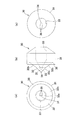
図1は本発明に係る弁体30を組み込んだYコネクタ1の断面図である。本実施の形態では、図1に示すYコネクタ1を基準に、図1の左側を「先端側」、右側を「基端側」と定義して説明する。
Hereinafter, embodiments of the present invention will be described in detail with reference to the drawings.
FIG. 1 is a cross-sectional view of a Y connector 1 incorporating a
図1に示すように、Yコネクタ1は、例えば、カテーテル2のハブ等とカテーテル接続部4を接続して使用される。これにより、Yコネクタ1を通じてカテーテル2内に、ガイドワイヤのような長尺部材からなる挿入物3を挿入できるように構成されている。
As shown in FIG. 1, the Y connector 1 is used by connecting a hub or the like of the
Yコネクタ1は、Y字状の筒状本体部材10と、筒状本体部材10の先端部(遠位側)に設けたカテーテル接続部4と、筒状本体部材10の基端側(近位側)に設けたキャップ部材20と、筒状本体部材10内に組み込んだ弁体30とを有している。以下、各部の構成について説明する。
The Y connector 1 includes a Y-shaped cylindrical
図1に示すように、Y字状の筒状本体部材10は、先端から基端にわたって貫通するチューブ状の本体部11と、本体部11の途中部から斜めに分岐するチューブ状の分岐部12とを有し、分岐部12の外端部にはシリンジまたは三方活栓を接続するための接続部13が形成され、本体部11の基端部の外周部にはキャップ部材20を取付けるための雄ネジ14が形成されている。
As shown in FIG. 1, a Y-shaped cylindrical
本体部11内には本体内腔部15が形成され、分岐部12内には本体内腔部15に連通する分岐内腔部16が形成され、シリンジまたは三方活栓により分岐内腔部16に供給した造影剤や生理食塩水は、分岐内腔部16及び弁体30よりも先端側の本体内腔部15を経て、Yコネクタ1に接続したカテーテル2に注入されるように構成されている。なお、Yコネクタ1が医療機器に相当し、本体内腔部15が医療機器の流体通路に相当する。
A main
本体内腔部15は、分岐内腔部16の連通部よりも基端側の途中部に形成した、先端側へ向けて縮径するテーパ面からなる環状の段差部15aと、段差部15aよりも先端側(遠位側)に形成した小径部15bと、段差部15aよりも基端側(近位側)に形成した大径部15cとを有している。
The main
キャップ部材20は、本体部11の雄ネジ14に螺合する雌ネジ21を形成したキャップ本体22と、キャップ本体22の中央部から先端側へ突出する円筒状の操作筒部23とを有し、操作筒部23を本体内腔部15の大径部15cに内嵌させて、筒状本体部材10の雄ネジ14に雌ネジ21を螺合させることによって、筒状本体部材10に組み付けられている。
The
弁体30は、操作筒部23の先端側において本体内腔部15の大径部15cに液密状に内嵌され、本体部11の雄ネジ14に対するキャップ部材20の雌ネジ21のねじ込み量に応じて、操作筒部23の先端部で大径部15cの先端側へ押し操作されるように構成されている。また、弁体30の先端側への移動は段差部15aにより規制され、これにより小径部15b内に弁体30が押し出されないように構成されている。更に、弁体30が段差部15aに圧接されることで、弁体30の外周部と本体内腔部15とが液密状に保持されるとともに、段差部15aのテーパ面により弁体30が縮径方向に圧縮変形するように構成されている。
The
ガイドワイヤなどの挿入物3は、操作筒部23の貫通孔24に挿入されて、Yコネクタ1内に導入され、弁体30の切込部35及び本体内腔部15の小径部15bを通って、Yコネクタ1に接続されたカテーテル2内に挿入されている。そして、挿入物3が弁体30の切込部35に常時液密状に挿入されることで、キャップ部材20の螺合を緩めた状態においても、弁体30に挿入物3を挿入した状態で、本体内腔部15の先端側と基端側とが弁体30を介して液密状に常時仕切られるように構成されている。ただし、キャップ部材20を締め付けると、弁体30の外周部が段差部15aに圧接されるとともに、弁体30が縮径方向に圧縮変形して、弁体30の内面が挿入物3に強く圧接されるので、挿入物3の移動が規制されるとともに、本体内腔部15の先端側に大きな流体圧が作用した場合でも、弁体30の外周部と本体内後部15間が液密状に保持されるとともに、挿入物3と弁体30間が液密状に保持される。なお、本体内腔部15の先端側に作用する流体圧としては、Yコネクタ1先端側からうける血圧やYコネクタ1に接続されたシリンジからの流体の注入圧などがある。
An
なお、筒状本体部材10及びキャップ部材20の素材としては、ポリ塩化ビニル、ポリエチレン、ポリプロピレン、ポリカーボネート、アクリル樹脂、ポリアミドのような各種合成樹脂を好適に採用できるが、これに限定されるものではない。
In addition, as a raw material of the cylindrical
次に、弁体30の具体的構成について説明する。
図1〜図6に示すように、弁体30は、本体内腔部15の大径部15cに液密状に内嵌する円筒状の筒部31と、筒部31の先端部に連なって弁体30の先端側部分に本体内腔部15の先端側へ突出状に形成した先端へ行くにしたがって縮径するテーパ部32と、筒部31及びテーパ部32の内側に形成したガイドワイヤなどの挿入物3よりも大径のガイド孔33と、挿入物3が挿入されるテーパ部32の先端部の挿入部34に形成した切込部35と、テーパ部32の外周部に先端側へ突出状に形成した環状のシール部36とを備えている。ただし、弁体30の構成は、適用するYコネクタ1の構成などに応じて適宜に変更することが可能で、例えば円板状の弁体を採用することも可能である。
Next, a specific configuration of the
As shown in FIGS. 1 to 6, the
弁体30を構成する素材としては、シリコーンゴム、ウレタンゴム、フッ素ゴム、アクリルゴム等の各種剛性ゴム、天然ゴム、またはポリアミド系、ポリエステル系等の各種熱可塑性エラストマーのような弾性材料を採用できる。
As a material constituting the
弁体30の外径は本体内腔部15の大径部15cよりも大きい寸法に形成され、弁体30を縮径方向に圧縮しながら大径部15cに内嵌することで、弁体30と大径部15c間における液密性が得られるように構成されている。
The outer diameter of the
テーパ部32の先端側には第1テーパ面32aが形成され、テーパ部32の基端側には第1テーパ面32aよりも中心線とのなす角度の大きい第2テーパ面32bが形成されている。テーパ部32の先端部の挿入部34には挿入物3を挿入可能とする切込部35が形成され、第1テーパ面32aにより本体内腔部15の先端側に作用する流体圧によって弁体30は中心方向に押し込まれる。これらの圧力によっても弁体30内に設けられる切込部35が閉鎖されて、Yコネクタ1の液密性が保たれる。
A first tapered
弁体30の基端側に形成される第2テーパ面32bは、中心線に対する角度が本体内腔部15の段差部15aのテーパ面と同じになるように形成され、キャップ部材20を締め込んだときに、弁体30が本体内腔部15の先端側へ押し出されることを防止できるように構成されている。
The
シール部36の内周面には先端側へ行くにしたがって拡径するテーパ面が形成され、これによりシール部36が本体内腔部15の先端側に作用する流体圧で大径部15cの内面に押し付けられるため、弁体30の外周面からの造影剤や生理食塩水のような流体の流出を防止できるように構成されている。
The inner peripheral surface of the
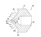
図4〜図6に示すように、弁体30の先端部の挿入部34には、挿入部34の先端側から基端側への全長に亘って、挿入物3の挿入中心から半径方向の外側へ延びる幅Wを有する切込部35が形成され、切込部35の内面の少なくとも一部の面は、その一部の面に接する平面と、挿入中心の中心線CLの方向(弁体30の中心線の方向)との交差する最小角θが、0°<θ<90°になるように構成されている。
As shown in FIGS. 4 to 6, the
具体的には、図6に示すように、挿入物3の挿入中心から半径方向外方側へ延びる幅Wを有し、該挿入中心の中心線CLに沿って螺旋状に周回する帯状の2個の切込部35を、挿入中心を挟んで半径方向両側に設けることができる。図5は、図6のa-a線、b-b線、c-c線での断面図で、切込部35の内面は自然状態で常に閉塞しており、その断面は一文字状に形成されている。
Specifically, as shown in FIG. 6, a band-shaped 2 having a width W extending radially outward from the insertion center of the
切込部35の幅Wの寸法は特に限定されないが、挿入物3の外径に応じて設定することが好ましく、例えば、挿入物3としてガイドワイヤをYコネクタ1内に導入するために用いるガイドワイヤインサータを用いる場合には、最大外径が0.9mmであれば、幅Wを0.45mm以上に設定することで、挿入物3による切込部35の損傷を抑制できる。なお、幅Wは、大きく設定するほど摺動性は向上する。
The dimension of the width W of the
図6に示すような形状の切込部35は、例えばドリル状の加工ツール40を用いて加工できる。具体的には、図7に示すように、加工ツール40として、回転中心RCから半径方向外方側へ延びる幅を有し、回転中心RCに沿って螺旋状に周回する2枚の帯状の切刃41を備えたものを用いることになる。加工ツール40及び弁体30を同軸上に配置して、加工ツール40を回転させながら送り操作して、弁体30の挿入部34全長にわたって切込部35を形成し、その後加工ツール40を逆回転させながら、弁体30の挿入部34から加工ツール40を引き抜くことで、切込部35を形成することになる。加工ツールではなく弁体を回転させて同様に形成してもよい。より具体的には、加工ツール40を挿入部34に挿入することで、弾性材料で形成されている弁体30は加工ツール40の挿入とともに延伸される。そして、徐々に加工ツール40を推し進めると弁体30は加工ツール40の形状に密着しながら引き裂かれ、これにより切込部35が形成されることになる。また、延伸された状態で形成された切込部35は、加工ツール40を引き戻すと弾性によって弁体30の中心方向に収縮するため、図6に示すように、自然状態では閉塞された切込部35が形成される。
The
なお、弁体30の切込部35を加工する際にシリコーンオイルを添加することで切込部35の内面にシリコーン層を形成してもよい。この場合には、切込部35の内面に摩擦係数が小さいシリコーン層が形成されることによって、切込部35に対する挿入物3の摺動性が向上する。またシリコーン層によって切込部35の内面同士の隙間が密になるため、切込部35における液密性を向上させることができる。また、加工ツール40の先端部に先鋭部を突出状に形成し、弾性材料からなる挿入部34を圧縮変形させながら、切込みを入れるように構成することも好ましい。更に、図8のような4個の切込部35を十文字状に配置したものや、3個の切込部35をY字状に配置したものなどは、切込部35に適合する形状及び大きさの切刃を有する加工ツールを用いて上記と同様に加工することができる。
Note that a silicone layer may be formed on the inner surface of the
また、弁体30が組み込まれる医療機器に挿入される長尺部材の材質・外径・硬度によって摺動性は異なるため、加工ツール40の外径や切込部35の挿通中心の軸方向の長さを調整することで実施形態と同様の作用・効果が得られる。
In addition, since the slidability varies depending on the material, outer diameter, and hardness of the long member inserted into the medical device in which the
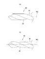
なお、挿入中心の中心線CLに直交する断面での切込部35の形状は、直線状だけでなく、湾曲状などの非直線状に形成することもできる。また、切込部35の個数は任意に設定することが可能で、1個だけ形成することもできるし、挿入中心の中心線CLを中心に周方向に間隔をあけて3個以上設けることもできる。例えば、図8に示すように、4個の切込部35を周方向に90°の間隔をあけて形成し、挿入中心の中心線に直交する断面での切込部35の形状を十文字状に形成することができる。更に、複数の切込部35を形成する場合には、切込部35の幅Wを同じに設定することもできるが、異なる幅の切込部35を設け、中心線CLからの乖離距離が変化するように構成することも可能である。更にまた、切込部35の内面の少なくとも一部の面が、その一部の面に接する平面と、挿入中心の中心線CLの方向との交差する最小角θが、0°<θ<90°になるように構成されていれば、任意の形状の切込部を形成することが可能であり、弁体30の挿入部34における切込部35を形成した位置に、切込部35に代えて、例えば図9、図10に示すような、三角波状の切込部35Aや、正弦波状の切込部35Bを形成することも可能である。また、この切込部35A、35Bにおいては、中心線CLからの乖離距離ELが変化するとともに、中心線CLに対する進入角が変化することになる。なお、「乖離距離ELが変化する」とは、図9(b)、図10(b)に示すように、挿入中心の中心線CLに対する交差断面での切込部35A、35Bの形状が、中心線CL方向の複数箇所において、中心線CLからの乖離距離ELを変えることを意味する。また、「進入角が変化する」とは、図9、図10に示すように、切込部35A、35Bが、中心線CL方向に沿うことなく(0°ではなく)、進入角度を有しており、その進入角度を切込部35A、35Bにおける中心線CL方向の複数箇所において変えることを意味する。例えば、図9に示す切込部35Aのように、進入角度を交互に変化させたり、図10に示す切込部35Bのように、進入角度を連続的に変化させることになる。
Note that the shape of the
このような構成の切込部35を形成した弁体30では、切込部35の内面が自然状態で常に閉塞されており、しかも切込部35の形状が複雑なので、造影剤・生理食塩水または血液等の流体が切込部35を通ってYコネクタ1外へ流出しにくくなる。また、切込部35に挿入物3を挿入した状態で、切込部35の内面が、弁体30を構成する素材の弾性により、挿入物3の外面に圧接されるので、弁体30と挿入物3間における液密性が保たれる。しかも、最小角θを0°<θ<90°に設定しているので、弁体30よりも先端側の本体内腔部15の流体圧によって、弁体30における切込部35の先端側部分が挿入物3に圧接される方向に押されて、単に挿入中心の軸方向、即ち最小角θが0°の切込みを形成した従来の弁体30と比較して、挿入物3と弁体30間における液密性が高められることになる。また、このように液密性が高められるので、切込部35の中心線方向の長さを短く設定して、挿入物3に対する弁体30の摺動抵抗を小さくでき、挿入物3の操作性を向上できる。しかも、図6に示す切込部35のように、挿入中心の中心線CLに沿って螺旋状に周回するように形成すると、切込部35により形成される挿入部34の切片が、切込部35に挿入される挿入物3の外形に沿って拡縮するので、挿入物3と切込部35の内面間における隙間を小さくして、液密性を一層向上することができる。
In the
なお、本実施の形態では、Yコネクタ1に本発明の弁体30を適用した場合について説明したが、これに限定されず、シースイントロデューサ、マイクロカテーテルおよびバルーンカテーテル等の各カテーテル等の医療機器に対しても本発明の弁体30を適用することができる。例えばガイドワイヤルーメンと造影剤を含むバルーン拡張用流体が通過する内腔が併用される単一管腔バルーンカテーテルに組み入れた場合、弁体30によってカテーテル内腔には生体内からの血液の流入が抑制されるため、X線下におけるバルーンの視認性低下が抑制される。
In the present embodiment, the case where the
また、挿入物3としては、適用する医療機器に応じて、ガイドワイヤのような長尺部材以外に、注射針などの短尺物や、薬液などの流体を挿入することもできる。
In addition to the long member such as a guide wire, a short object such as an injection needle or a fluid such as a drug solution can be inserted as the
次に、弁体30の作用効果を確認するために行った評価試験について説明する。
Next, an evaluation test performed for confirming the effect of the
<評価試験1>
切込部の挿入中心の軸方向の長さに関する評価試験を下記の通り行った。
<Evaluation test 1>
An evaluation test on the axial length of the insertion center of the cut portion was performed as follows.
1.弁体
弁体として、切込部の挿入中心の軸方向の長さが、0.5mm、1.0mm、1.5mmの3種の弁体をシリコーンゴムで作製した。そして、弁体の先端部に、外径0.9mmの加工ツール40で切込部を加工した。
1. Valve body Three types of valve bodies having axial lengths of 0.5 mm, 1.0 mm, and 1.5 mm in the insertion center of the cut portion were made of silicone rubber. And the notch part was processed into the front-end | tip part of the valve body with the
2.弁性能評価
作製した3種の弁体をYコネクタ1に組み込み、Yコネクタ1内に水を満たした上で200mmH2Oの内圧を付与した。水圧下でYコネクタ1内からの水の流出を確認するとともに、外径0.25mmのガイドワイヤを挿入したときの水漏れの有無を確認した。その結果を表1に示す。ただし、水漏れの発生しなかった弁体は「○」で示し、水漏れの発生した弁体は「×」で示した。
2. Valve performance evaluation The three types of produced valve bodies were assembled in the Y connector 1 and the Y connector 1 was filled with water, and then an internal pressure of 200 mmH 2 O was applied. While confirming the outflow of water from the Y connector 1 under water pressure, the presence or absence of water leakage when a guide wire having an outer diameter of 0.25 mm was inserted was confirmed. The results are shown in Table 1. However, a valve element that did not cause water leakage was indicated by “◯”, and a valve element that caused water leakage was indicated by “x”.
3.摺動性評価
作製した3種の弁体をYコネクタ1に配置し、Yコネクタ1内に外径0.25mmのガイドワイヤ(ポリテトラフルオロエチレンコーティング)を挿入して、摺動性を触感にて評価した。その結果を表1に示す。ただし、摺動抵抗の大きな弁体は「×」で示し、摺動抵抗の小さい弁体は「○」で示した。
3. Evaluation of sliding property Three kinds of manufactured valve bodies are arranged in the Y connector 1 and a guide wire (polytetrafluoroethylene coating) having an outer diameter of 0.25 mm is inserted into the Y connector 1 so that the sliding property is tactile. And evaluated. The results are shown in Table 1. However, a valve element having a large sliding resistance is indicated by “x”, and a valve element having a small sliding resistance is indicated by “◯”.

<評価試験例2>
切込部の加工径に関する評価試験を下記の通り行った。
<Evaluation Test Example 2>
An evaluation test on the machining diameter of the cut portion was performed as follows.
1.弁体
弁体として、外径が0.9mm、1.1mmの2種類の加工ツールを用いて切込部35を形成した2種の弁体と、外径が1.1mmの加工ツールを用いて、シリコーンオイル付与して切込部を形成した弁体の計3種の弁体をシリコーンゴムで作製した。
1. Valve body As the valve body, two kinds of valve bodies in which the
2.弁性能評価
作製した3種の弁体をYコネクタ1に配置し、Yコネクタ1内に水を満たした上で200mmH2Oの内圧を付与した。水圧下でYコネクタ1内からの水の流出を確認するとともに、外径0.25mmのガイドワイヤを挿入したときの水漏れの有無を確認した。その結果を表2に示す。ただし、水漏れの発生しなかった弁体は「○」で示した。
2. Valve performance evaluation The produced three types of valve bodies were arranged in the Y connector 1, and after filling the Y connector 1 with water, an internal pressure of 200 mmH 2 O was applied. While confirming the outflow of water from the Y connector 1 under water pressure, the presence or absence of water leakage when a guide wire having an outer diameter of 0.25 mm was inserted was confirmed. The results are shown in Table 2. However, the valve body where no water leak occurred is indicated by “◯”.
3.摺動性評価
作製した2種の弁体が配置されたYコネクタ1内に生理食塩水と造影剤の混合液(体積比1:1)を満たし、外径0.35mmのガイドワイヤを挿入して摺動させて摺動荷重をフォースゲージ(日本電産シンポ社製)で測定した。ガイドワイヤは速度10mm/sec、ストローク20mmで5往復摺動し、押込み時と引き戻し時のそれぞれのピーク荷重の平均値を測定した。その結果を表2に示す。
3. Sliding performance evaluation The Y connector 1 in which the prepared two types of valve bodies are arranged is filled with a mixed solution of physiological saline and contrast medium (volume ratio 1: 1), and a guide wire having an outer diameter of 0.35 mm is inserted. The sliding load was measured with a force gauge (manufactured by Nidec Symposium). The guide wire was slid 5 reciprocations at a speed of 10 mm / sec and a stroke of 20 mm, and the average value of each peak load at the time of pushing and pulling was measured. The results are shown in Table 2.
表1と表2から、Yコネクタ1に挿入されるカテーテルの外径によって切込部の挿入中心の軸方向の長さと加工方法を設定することで、弁性能と摺動性を両立できることを確認した。 From Table 1 and Table 2, it is confirmed that both the valve performance and slidability can be achieved by setting the axial length of the insertion center of the incision and the processing method according to the outer diameter of the catheter inserted into the Y connector 1 did.
1 Yコネクタ 2 カテーテル
3 挿入物 4 カテーテル接続部
10 筒状本体部材 11 本体部
12 分岐部 13 接続部
14 雄ネジ 15 本体内腔部
15a 段差部 15b 小径部
15c 大径部 16 分岐内腔部
20 キャップ部材 21 雌ネジ
22 キャップ本体 23 操作筒部
24 貫通孔
30 弁体 31 筒部
32 テーパ部 32a 第1テーパ面
32b 第2テーパ面 33 ガイド孔
34 挿入部 35 切込部
36 シール部
35A 切込部 35B 切込部
40 加工ツール 41 切刃
DESCRIPTION OF SYMBOLS 1
Claims (12)
上記弁体は、挿入物が挿入される挿入部を含み、
上記挿入部は、遠位側から近位側へと伸びる自身の全長に亘って、上記挿入物の挿入中心から半径方向の外側へ延びる幅を有する切込部を含み、
上記切込部では、その切込部の内面の少なくとも一部の面が、下記条件式(1)を満たす医療機器用弁体。
0°<θ<90°・・・・・(1)
ただし、
θ:上記内面の少なくとも一部の面は、上記挿入物が挿入される軸における遠位側からみて、近位側に向かって角度を有しており、その一部の面に接する平面と、上記挿入中心の軸方向との交差する最小角
である。 In the valve body for a medical device arranged in a fluid passage in the medical device,
The valve body includes an insertion portion into which an insert is inserted,
The insert includes a notch having a width extending radially outward from the insertion center of the insert over its entire length extending from the distal side to the proximal side,
In the said notch part, the valve body for medical devices in which at least one surface of the inner surface of the notch part satisfy | fills the following conditional expression (1).
0 ° <θ <90 ° (1)
However,
θ: At least a part of the inner surface has an angle toward the proximal side when viewed from the distal side in the axis in which the insert is inserted, and a plane in contact with the part of the surface; This is the minimum angle that intersects the axial direction of the insertion center.
弾性材料にて成形された弁体のうちの挿入物が挿入される挿入部に、加工ツールを用いて切込部を形成する切込工程を備え、
前記切込工程において、前記加工ツールとして、回転中心軸から半径方向外方側へ延びる幅を有し、回転中心軸に沿って螺旋状に周回する帯状の切刃を備えた加工ツールを用い、前記加工ツールを回転させながら送り操作して、前記弁体の挿入部にその全長にわたって切込部を形成する、
ことを特徴とする医療機器用弁体の製造方法。
A method for manufacturing a valve body for a medical device disposed in a fluid passage of the medical device,
The insertion part into which the insert of the valve body formed of an elastic material is inserted includes a cutting process for forming a cutting part using a processing tool,
In the cutting step, as the processing tool, using a processing tool having a band-shaped cutting blade having a width extending radially outward from the rotation center axis and spirally wound along the rotation center axis, A feed operation is performed while rotating the processing tool, and a cut portion is formed over the entire length of the insertion portion of the valve body.
The manufacturing method of the valve body for medical devices characterized by the above-mentioned.
Priority Applications (1)
| Application Number | Priority Date | Filing Date | Title |
|---|---|---|---|
| JP2012070787A JP5928064B2 (en) | 2012-03-27 | 2012-03-27 | MEDICAL DEVICE VALVE, MEDICAL DEVICE, AND METHOD FOR MANUFACTURING MEDICAL DEVICE VALVE |
Applications Claiming Priority (1)
| Application Number | Priority Date | Filing Date | Title |
|---|---|---|---|
| JP2012070787A JP5928064B2 (en) | 2012-03-27 | 2012-03-27 | MEDICAL DEVICE VALVE, MEDICAL DEVICE, AND METHOD FOR MANUFACTURING MEDICAL DEVICE VALVE |
Publications (2)
| Publication Number | Publication Date |
|---|---|
| JP2013202068A true JP2013202068A (en) | 2013-10-07 |
| JP5928064B2 JP5928064B2 (en) | 2016-06-01 |
Family
ID=49521833
Family Applications (1)
| Application Number | Title | Priority Date | Filing Date |
|---|---|---|---|
| JP2012070787A Active JP5928064B2 (en) | 2012-03-27 | 2012-03-27 | MEDICAL DEVICE VALVE, MEDICAL DEVICE, AND METHOD FOR MANUFACTURING MEDICAL DEVICE VALVE |
Country Status (1)
| Country | Link |
|---|---|
| JP (1) | JP5928064B2 (en) |
Cited By (2)
| Publication number | Priority date | Publication date | Assignee | Title |
|---|---|---|---|---|
| WO2016056376A1 (en) * | 2014-10-08 | 2016-04-14 | 日本ライフライン株式会社 | Chemical ablation device and chemical ablation system |
| JP2019534133A (en) * | 2016-11-09 | 2019-11-28 | ボストン サイエンティフィック リミテッド | Hemostatic valve structure for introducer sheath |
Citations (13)
| Publication number | Priority date | Publication date | Assignee | Title |
|---|---|---|---|---|
| JPS59133877A (en) * | 1983-01-18 | 1984-08-01 | Terumo Corp | Valve element |
| JPH01139077A (en) * | 1987-09-21 | 1989-05-31 | Cordis Corp | Valve for medical instrument |
| JPH03114475A (en) * | 1989-09-29 | 1991-05-15 | Terumo Corp | Medical valve disc, preparation thereof and catheter fitted with valve disc |
| JPH0528351U (en) * | 1991-06-04 | 1993-04-16 | 株式会社トツプ | Valve |
| US5273546A (en) * | 1991-08-01 | 1993-12-28 | Medtronic, Inc. | Hemostasis valve |
| US5409464A (en) * | 1994-05-13 | 1995-04-25 | Cordis Corporation | Intravascular catheter having barrier valve |
| US5520655A (en) * | 1994-07-15 | 1996-05-28 | Cordis Corporation | Catheter hemostasis valve |
| EP0771574A1 (en) * | 1995-11-01 | 1997-05-07 | Cordis Corporation | Gasket for catheter hemostasis valve |
| JP2001149487A (en) * | 1999-11-18 | 2001-06-05 | Joline Gmbh & Co Kg | Device for inserting objective in blood vessel of patient |
| JP2005503838A (en) * | 2000-12-19 | 2005-02-10 | キンバリー クラーク ワールドワイド インコーポレイテッド | Improved sealing valve assembly for medical supplies |
| EP1920700A1 (en) * | 2006-11-13 | 2008-05-14 | Pentax Europe GmbH | Seal element |
| US20100312190A1 (en) * | 2009-06-09 | 2010-12-09 | Oscor Inc. | Low insertion force hemostasis valve for vascular introducer |
| JP2011510686A (en) * | 2007-06-22 | 2011-04-07 | メディカル コンポーネンツ,インコーポレイテッド | Peelable sheath assembly with hemostatic valve |
-
2012
- 2012-03-27 JP JP2012070787A patent/JP5928064B2/en active Active
Patent Citations (13)
| Publication number | Priority date | Publication date | Assignee | Title |
|---|---|---|---|---|
| JPS59133877A (en) * | 1983-01-18 | 1984-08-01 | Terumo Corp | Valve element |
| JPH01139077A (en) * | 1987-09-21 | 1989-05-31 | Cordis Corp | Valve for medical instrument |
| JPH03114475A (en) * | 1989-09-29 | 1991-05-15 | Terumo Corp | Medical valve disc, preparation thereof and catheter fitted with valve disc |
| JPH0528351U (en) * | 1991-06-04 | 1993-04-16 | 株式会社トツプ | Valve |
| US5273546A (en) * | 1991-08-01 | 1993-12-28 | Medtronic, Inc. | Hemostasis valve |
| US5409464A (en) * | 1994-05-13 | 1995-04-25 | Cordis Corporation | Intravascular catheter having barrier valve |
| US5520655A (en) * | 1994-07-15 | 1996-05-28 | Cordis Corporation | Catheter hemostasis valve |
| EP0771574A1 (en) * | 1995-11-01 | 1997-05-07 | Cordis Corporation | Gasket for catheter hemostasis valve |
| JP2001149487A (en) * | 1999-11-18 | 2001-06-05 | Joline Gmbh & Co Kg | Device for inserting objective in blood vessel of patient |
| JP2005503838A (en) * | 2000-12-19 | 2005-02-10 | キンバリー クラーク ワールドワイド インコーポレイテッド | Improved sealing valve assembly for medical supplies |
| EP1920700A1 (en) * | 2006-11-13 | 2008-05-14 | Pentax Europe GmbH | Seal element |
| JP2011510686A (en) * | 2007-06-22 | 2011-04-07 | メディカル コンポーネンツ,インコーポレイテッド | Peelable sheath assembly with hemostatic valve |
| US20100312190A1 (en) * | 2009-06-09 | 2010-12-09 | Oscor Inc. | Low insertion force hemostasis valve for vascular introducer |
Cited By (4)
| Publication number | Priority date | Publication date | Assignee | Title |
|---|---|---|---|---|
| WO2016056376A1 (en) * | 2014-10-08 | 2016-04-14 | 日本ライフライン株式会社 | Chemical ablation device and chemical ablation system |
| JP2016073523A (en) * | 2014-10-08 | 2016-05-12 | 日本ライフライン株式会社 | Chemical ablation device and chemical ablation system |
| JP2019534133A (en) * | 2016-11-09 | 2019-11-28 | ボストン サイエンティフィック リミテッド | Hemostatic valve structure for introducer sheath |
| US11779743B2 (en) | 2016-11-09 | 2023-10-10 | Boston Scientific Limited | Hemostasis valve design for introducer sheath |
Also Published As
| Publication number | Publication date |
|---|---|
| JP5928064B2 (en) | 2016-06-01 |
Similar Documents
| Publication | Publication Date | Title |
|---|---|---|
| CN104039384B (en) | Multiple use stretching and non-penetrating blood control valves | |
| US9764085B2 (en) | Catheter assemblies with valves and related methods | |
| US9463314B2 (en) | Delivery catheter apparatus and methods | |
| AU2012318542B2 (en) | Multiple use blood control valve with center and circumferential slits | |
| EP3352839B1 (en) | Cross slit gasket for introducer sheath | |
| AU2015250124A1 (en) | Ported catheter or female luer fitting with antimicrobial septum | |
| US11904115B2 (en) | Catheter assembly | |
| WO2012015683A1 (en) | Catheter apparatus | |
| JP2007089607A (en) | Introducer sheath | |
| JP5928064B2 (en) | MEDICAL DEVICE VALVE, MEDICAL DEVICE, AND METHOD FOR MANUFACTURING MEDICAL DEVICE VALVE | |
| US10842981B2 (en) | Hemostasis valves and methods for making and using hemostasis valves | |
| US8690834B2 (en) | Medical device with multi-port inflatable hemostatic valve system | |
| CN110536714B (en) | Loading tool for use with medical devices | |
| US20220203073A1 (en) | Catheter assembly | |
| US11413427B2 (en) | Introducer hub assembly having cross-slit seal | |
| JP2016150170A (en) | Introducer sheath and introducer sheath set | |
| US10737086B2 (en) | Hemostasis valves and methods for making and using hemostasis valves | |
| JP2005329063A (en) | Dilator | |
| JPH0230695B2 (en) | ||
| JP2010200788A (en) | Medical valve body and medical insertion assisting device | |
| US20240139477A1 (en) | Catheter assembly | |
| JP6069819B2 (en) | Medical insertion aid | |
| JP2022148511A (en) | catheter | |
| JP2018166919A (en) | Sheath for introducer and introducer |
Legal Events
| Date | Code | Title | Description |
|---|---|---|---|
| A621 | Written request for application examination |
Free format text: JAPANESE INTERMEDIATE CODE: A621 Effective date: 20150121 |
|
| A131 | Notification of reasons for refusal |
Free format text: JAPANESE INTERMEDIATE CODE: A131 Effective date: 20151020 |
|
| A977 | Report on retrieval |
Free format text: JAPANESE INTERMEDIATE CODE: A971007 Effective date: 20151023 |
|
| A521 | Request for written amendment filed |
Free format text: JAPANESE INTERMEDIATE CODE: A523 Effective date: 20151218 |
|
| TRDD | Decision of grant or rejection written | ||
| A01 | Written decision to grant a patent or to grant a registration (utility model) |
Free format text: JAPANESE INTERMEDIATE CODE: A01 Effective date: 20160329 |
|
| A61 | First payment of annual fees (during grant procedure) |
Free format text: JAPANESE INTERMEDIATE CODE: A61 Effective date: 20160411 |
|
| R150 | Certificate of patent or registration of utility model |
Ref document number: 5928064 Country of ref document: JP Free format text: JAPANESE INTERMEDIATE CODE: R150 |
|
| R250 | Receipt of annual fees |
Free format text: JAPANESE INTERMEDIATE CODE: R250 |
|
| R250 | Receipt of annual fees |
Free format text: JAPANESE INTERMEDIATE CODE: R250 |
|
| R250 | Receipt of annual fees |
Free format text: JAPANESE INTERMEDIATE CODE: R250 |
|
| R250 | Receipt of annual fees |
Free format text: JAPANESE INTERMEDIATE CODE: R250 |
|
| R250 | Receipt of annual fees |
Free format text: JAPANESE INTERMEDIATE CODE: R250 |
|
| R250 | Receipt of annual fees |
Free format text: JAPANESE INTERMEDIATE CODE: R250 |