JP2013200957A - Electric wire holding structure - Google Patents

Electric wire holding structure Download PDF

Info

Publication number
JP2013200957A
JP2013200957A JP2012067130A JP2012067130A JP2013200957A JP 2013200957 A JP2013200957 A JP 2013200957A JP 2012067130 A JP2012067130 A JP 2012067130A JP 2012067130 A JP2012067130 A JP 2012067130A JP 2013200957 A JP2013200957 A JP 2013200957A
Authority
JP
Japan
Prior art keywords
electric wire
wire holder
electric
electric wires
groove
Prior art date
Legal status (The legal status is an assumption and is not a legal conclusion. Google has not performed a legal analysis and makes no representation as to the accuracy of the status listed.)
Pending
Application number
JP2012067130A
Other languages
Japanese (ja)
Inventor
Shingo Chiba
真吾 千葉
Current Assignee (The listed assignees may be inaccurate. Google has not performed a legal analysis and makes no representation or warranty as to the accuracy of the list.)
Yazaki Corp
Original Assignee
Yazaki Corp
Priority date (The priority date is an assumption and is not a legal conclusion. Google has not performed a legal analysis and makes no representation as to the accuracy of the date listed.)
Filing date
Publication date
Application filed by Yazaki Corp filed Critical Yazaki Corp
Priority to JP2012067130A priority Critical patent/JP2013200957A/en
Priority to PCT/JP2013/059160 priority patent/WO2013141408A1/en
Priority to KR20147026637A priority patent/KR20140127902A/en
Priority to DE112013001705.9T priority patent/DE112013001705T5/en
Priority to US14/387,324 priority patent/US20150075865A1/en
Priority to CN201380016142.0A priority patent/CN104247155A/en
Publication of JP2013200957A publication Critical patent/JP2013200957A/en
Pending legal-status Critical Current

Links

Images

Classifications

    • HELECTRICITY
    • H01ELECTRIC ELEMENTS
    • H01RELECTRICALLY-CONDUCTIVE CONNECTIONS; STRUCTURAL ASSOCIATIONS OF A PLURALITY OF MUTUALLY-INSULATED ELECTRICAL CONNECTING ELEMENTS; COUPLING DEVICES; CURRENT COLLECTORS
    • H01R4/00Electrically-conductive connections between two or more conductive members in direct contact, i.e. touching one another; Means for effecting or maintaining such contact; Electrically-conductive connections having two or more spaced connecting locations for conductors and using contact members penetrating insulation
    • H01R4/24Connections using contact members penetrating or cutting insulation or cable strands
    • HELECTRICITY
    • H01ELECTRIC ELEMENTS
    • H01RELECTRICALLY-CONDUCTIVE CONNECTIONS; STRUCTURAL ASSOCIATIONS OF A PLURALITY OF MUTUALLY-INSULATED ELECTRICAL CONNECTING ELEMENTS; COUPLING DEVICES; CURRENT COLLECTORS
    • H01R13/00Details of coupling devices of the kinds covered by groups H01R12/70 or H01R24/00 - H01R33/00
    • H01R13/58Means for relieving strain on wire connection, e.g. cord grip, for avoiding loosening of connections between wires and terminals within a coupling device terminating a cable
    • H01R13/582Means for relieving strain on wire connection, e.g. cord grip, for avoiding loosening of connections between wires and terminals within a coupling device terminating a cable the cable being clamped between assembled parts of the housing
    • H01R13/5829Means for relieving strain on wire connection, e.g. cord grip, for avoiding loosening of connections between wires and terminals within a coupling device terminating a cable the cable being clamped between assembled parts of the housing the clamping part being flexibly or hingedly connected to the housing
    • HELECTRICITY
    • H01ELECTRIC ELEMENTS
    • H01RELECTRICALLY-CONDUCTIVE CONNECTIONS; STRUCTURAL ASSOCIATIONS OF A PLURALITY OF MUTUALLY-INSULATED ELECTRICAL CONNECTING ELEMENTS; COUPLING DEVICES; CURRENT COLLECTORS
    • H01R4/00Electrically-conductive connections between two or more conductive members in direct contact, i.e. touching one another; Means for effecting or maintaining such contact; Electrically-conductive connections having two or more spaced connecting locations for conductors and using contact members penetrating insulation
    • H01R4/24Connections using contact members penetrating or cutting insulation or cable strands
    • H01R4/2416Connections using contact members penetrating or cutting insulation or cable strands the contact members having insulation-cutting edges, e.g. of tuning fork type
    • H01R4/242Connections using contact members penetrating or cutting insulation or cable strands the contact members having insulation-cutting edges, e.g. of tuning fork type the contact members being plates having a single slot
    • H01R4/2425Flat plates, e.g. multi-layered flat plates
    • H01R4/2429Flat plates, e.g. multi-layered flat plates mounted in an insulating base
    • H01R4/2433Flat plates, e.g. multi-layered flat plates mounted in an insulating base one part of the base being movable to push the cable into the slot
    • HELECTRICITY
    • H01ELECTRIC ELEMENTS
    • H01RELECTRICALLY-CONDUCTIVE CONNECTIONS; STRUCTURAL ASSOCIATIONS OF A PLURALITY OF MUTUALLY-INSULATED ELECTRICAL CONNECTING ELEMENTS; COUPLING DEVICES; CURRENT COLLECTORS
    • H01R9/00Structural associations of a plurality of mutually-insulated electrical connecting elements, e.g. terminal strips or terminal blocks; Terminals or binding posts mounted upon a base or in a case; Bases therefor
    • H01R9/22Bases, e.g. strip, block, panel
    • H01R9/24Terminal blocks
    • H01R9/2416Means for guiding or retaining wires or cables connected to terminal blocks
    • HELECTRICITY
    • H01ELECTRIC ELEMENTS
    • H01RELECTRICALLY-CONDUCTIVE CONNECTIONS; STRUCTURAL ASSOCIATIONS OF A PLURALITY OF MUTUALLY-INSULATED ELECTRICAL CONNECTING ELEMENTS; COUPLING DEVICES; CURRENT COLLECTORS
    • H01R2201/00Connectors or connections adapted for particular applications
    • H01R2201/26Connectors or connections adapted for particular applications for vehicles

Abstract

PROBLEM TO BE SOLVED: To provide an electric wire holding structure which makes a load, required for placing multiple electric wires in pressure contact with pressure contact terminals, small and prevents the deterioration of the stability of connection between the electric wires and the pressure contact terminals.SOLUTION: In an electric wire holding structure 1, multiple electric wire W are placed in pressure contact with pressure contact terminals 32 and held when parts of the multiple electric wires W are aligned and held and an electric wire holder 60 is attached to an electric wire holder attachment part 110 while being rotated. The electric wire holder attachment part 110 includes a pair of electric wire holder holding walls 140 that contact with the respective electric wires W so that the respective electric wires W are bent upward at both side parts 60c of the electric wire holder 60 and sandwich the electric wire holder 60 as well as upwardly bent portions W1 of the multiple electric wires W from the lateral side thereby holding the electric wire holder 60 when the electric wire holder 60 is attached to the electric wire holder attachment part 110 while being rotated.

Description

本発明は、複数の電線が圧接端子に圧接されて保持される電線保持構造に関する。   The present invention relates to an electric wire holding structure in which a plurality of electric wires are held in pressure contact with pressure contact terminals.

従来、複数の電線が圧接端子に圧接されて保持される電線保持構造は、複数の電線の一部が整列保持される電線ホルダーと、各電線が圧接される複数の圧接端子が設けられ、電線ホルダーの取り付け先となる電線ホルダー取付部と、を有し、電線ホルダーが電線ホルダー取付部に取り付けられることによって複数の電線が圧接端子に圧接されて保持される電線保持構造が用いられる。例えば、特許文献1には、複数の電線が圧接端子に同時に圧接される場合であっても、圧接に必要な荷重を小さく抑えることができるようにした電線保持構造が提案されている(例えば、特許文献1参照)。   Conventionally, a wire holding structure in which a plurality of electric wires are held in pressure contact with a press contact terminal is provided with an electric wire holder in which a part of the plurality of electric wires are aligned and held, and a plurality of press contact terminals to which each electric wire is press contacted. There is used an electric wire holding structure in which a plurality of electric wires are pressed against and held by press contact terminals when the electric wire holder is attached to the electric wire holder attaching portion. For example, Patent Document 1 proposes a wire holding structure that can suppress a load necessary for pressure contact even when a plurality of wires are pressed against a pressure contact terminal at the same time (for example, Patent Document 1).

特許文献1に記載の電線保持構造は、複数の電線の一部が整列保持され、複数の電線の延在方向に直交する方向の一端側に回動軸を有してなる電線ホルダーと、回動軸を軸支する軸支部および各電線が圧接される複数の圧接端子が設けられ、かつ電線ホルダーが軸支部によって軸支され、回動されながら取り付けられる電線ホルダー取付部と、を有してなり、電線ホルダーが電線ホルダー取付部に取り付けられた場合、複数の電線が圧接端子に圧接されて保持されるようになっている。   The electric wire holding structure described in Patent Document 1 includes an electric wire holder in which a part of a plurality of electric wires is aligned and held, and has a rotating shaft on one end side in a direction orthogonal to the extending direction of the plural electric wires. A shaft support portion that supports the dynamic shaft, and a plurality of press contact terminals to which each electric wire is press-contacted, and an electric wire holder is pivotally supported by the shaft support portion and attached while being rotated. Thus, when the electric wire holder is attached to the electric wire holder attaching portion, a plurality of electric wires are held in pressure contact with the press contact terminals.

特開2011−113802号公報JP 2011-113802 A

しかしながら、特許文献1に記載された電線保持構造は、電線ホルダー取付部によって複数の電線が導出される部分を避けるようにして電線ホルダーが保持されるので、電線ホルダーの保持力が弱くなり、電線ホルダーがガタつき、結果的に電線と圧接端子との接続安定性が低下するおそれがあった。   However, since the electric wire holding structure described in Patent Document 1 holds the electric wire holder so as to avoid a portion where a plurality of electric wires are led out by the electric wire holder mounting portion, the holding force of the electric wire holder becomes weak, As a result, there is a possibility that the stability of connection between the electric wire and the press contact terminal is lowered.

本発明は、上記に鑑みてなされたものであって、複数の電線を圧接端子に圧接する際に必要な荷重を小さく抑えるとともに、電線と圧接端子との接続安定性が低下することを防ぐことができる電線保持構造を提供することを目的とする。   The present invention has been made in view of the above, and suppresses a load required when a plurality of electric wires are press-contacted to a press contact terminal, and prevents a reduction in connection stability between the electric wire and the press contact terminal. It aims at providing the electric wire holding structure which can do.

上述した課題を解決し、目的を達成するために、本発明の請求項1に係る電線保持構造は、複数の電線の一部が整列保持され、前記複数の電線の延在方向に直交する方向の一端側に回動軸を有してなる電線ホルダーと、前記複数の電線の各電線が圧接される複数の圧接端子が設けられ、前記電線ホルダーが前記回動軸を軸支部によって軸支され、回動されながら取り付けられる電線ホルダー取付部と、を有してなり、前記電線ホルダーが前記電線ホルダー取付部に取り付けられた場合、前記複数の電線が前記圧接端子に圧接されて保持される電線保持構造において、前記電線ホルダー取付部は、前記電線ホルダーが回動されながら取り付けられる場合、前記各電線が前記電線ホルダーの両側部位置で上方に屈曲されるように各電線に当接され、前記複数の電線の上方に屈曲された部分とともに前記電線ホルダーを側方から挟み込むことによって前記電線ホルダーを保持する一対の電線ホルダー保持壁を有してなることを特徴とする。   In order to solve the above-described problems and achieve the object, the electric wire holding structure according to claim 1 of the present invention is a direction in which a part of the plurality of electric wires is aligned and held and is orthogonal to the extending direction of the plurality of electric wires. An electric wire holder having a rotating shaft on one end side thereof, and a plurality of press contact terminals to which the electric wires of the plurality of electric wires are press-contacted, and the electric wire holder is pivotally supported by a shaft support portion on the rotating shaft. An electric wire holder attaching portion that is attached while being rotated, and when the electric wire holder is attached to the electric wire holder attaching portion, the plurality of electric wires are held in pressure contact with the press contact terminals. In the holding structure, when the electric wire holder is attached while being rotated, the electric wire holder attaching portion is brought into contact with each electric wire so that the electric wires are bent upward at both side positions of the electric wire holder. Characterized by comprising a pair of electric wire holder holding walls for holding the electric wire holder by with bent portions above the plurality of electric wires to sandwich the electric wire holder from the side.

また、本発明の請求項2に係る電線保持構造は、上記の発明において、前記回動軸は、断面半円形状をなし、前記軸支部は、前記回動軸が上方から挿入可能に形成された溝からなり、かつ前記回動軸が断面半円形状の直線部分を溝の内縁に向けて挿入されるように溝幅が設定されてなる幅小溝部と、前記幅小溝部の下端に水平方向の段差面を形成するように溝幅が拡大され、溝の底で前記回動軸が前記直線部分を上方に向けるように回動される幅大溝部と、を含む軸受け溝部を有してなり、前記段差面は、前記電線ホルダーが回動の途中で上方へ移動された場合、前記回動軸の直線部分を形成する面に当接されることを特徴とする。   In the electric wire holding structure according to claim 2 of the present invention, in the above invention, the rotation shaft has a semicircular cross section, and the shaft support portion is formed so that the rotation shaft can be inserted from above. A narrow groove portion having a groove width set so that the linear axis portion having a semicircular cross section is inserted toward the inner edge of the groove, and a lower end of the narrow groove portion. A groove width that is widened so as to form a stepped surface in a direction, and a wide groove portion in which the rotation shaft is rotated so that the linear portion is directed upward at the bottom of the groove. Thus, when the electric wire holder is moved upward in the middle of rotation, the step surface is in contact with a surface forming a linear portion of the rotation shaft.

本発明の請求項1に係る電線保持構造は、前記電線ホルダーが前記軸支部によって軸支され、回動されながら前記複数の電線を前記圧接端子に圧接させ、しかもストレインリリーフ構造を適用し、前記一対の電線ホルダー保持壁が前記複数の電線の上方に屈曲された部分とともに前記電線ホルダーを側方から挟み込み、前記電線ホルダーを保持することによって、前記電線ホルダーのガタつきを抑えるようになっているので、複数の電線を圧接端子に圧接する際に必要な荷重を小さく抑えるとともに、電線と圧接端子との接続安定性が低下することを防ぐことができる。   In the electric wire holding structure according to claim 1 of the present invention, the electric wire holder is pivotally supported by the pivotal support portion, the plurality of electric wires are pressed against the press contact terminals while being rotated, and a strain relief structure is applied, A pair of electric wire holder holding walls sandwiches the electric wire holder from the side together with portions bent upward of the plurality of electric wires, and holds the electric wire holder, thereby suppressing rattling of the electric wire holder. Therefore, it is possible to suppress a load required when a plurality of electric wires are press-contacted to the press contact terminal, and to prevent a reduction in connection stability between the electric wire and the press contact terminal.

本発明の請求項2に係る電線保持構造は、前記電線ホルダーの回動の途中で、前記電線が、前記一対の電線ホルダー保持壁に接触され、反力により前記電線ホルダーが上方へ移動された場合、前記回動軸の直線部分を形成する面が前記段差面に当接され、前記段差面が梃子の原理における支点になって前記電線ホルダーが回動されるので、前記電線ホルダーが前記一対の電線ホルダー保持壁との間に前記複数の電線を位置させた状態で回動された場合であっても、回転の際に必要な荷重を小さく抑えることがことできる。   In the electric wire holding structure according to claim 2 of the present invention, the electric wire is brought into contact with the pair of electric wire holder holding walls during the rotation of the electric wire holder, and the electric wire holder is moved upward by a reaction force. In this case, the surface forming the linear portion of the pivot shaft is brought into contact with the stepped surface, and the stepped surface serves as a fulcrum in the principle of the lever so that the wire holder is rotated. Even when the plurality of electric wires are rotated between the electric wire holder holding wall and the electric wire holder holding wall, the load required for the rotation can be kept small.

図1は、本発明の実施例に係る電線保持構造が組み込まれた照明装置の分解斜視図である。FIG. 1 is an exploded perspective view of a lighting device incorporating a wire holding structure according to an embodiment of the present invention. 図2は、図1に示した電線ホルダーが取り付けられる前の照明装置の斜視図である。FIG. 2 is a perspective view of the lighting device before the electric wire holder shown in FIG. 1 is attached. 図3は、図2に示した電線ホルダー取付部周辺を拡大した図である。FIG. 3 is an enlarged view of the periphery of the electric wire holder mounting portion shown in FIG. 図4は、図3に示した電線ホルダー取付部周辺の上面図である。FIG. 4 is a top view of the periphery of the electric wire holder mounting portion shown in FIG. 図5は、図1に示した電線ホルダーを拡大した図である。FIG. 5 is an enlarged view of the electric wire holder shown in FIG. 図6は、図1に示した電線ホルダーの上押さえ部と下押さえ部とを重ね合わせる前の状態を示した斜視図である。FIG. 6 is a perspective view illustrating a state before the upper pressing portion and the lower pressing portion of the electric wire holder illustrated in FIG. 1 are overlapped. 図7は、図4に示した電線ホルダー取付部に電線ホルダーが取り付けられた状態を示した上面図である。FIG. 7 is a top view showing a state where the electric wire holder is attached to the electric wire holder attaching portion shown in FIG. 図8は、図7に示した電線ホルダーおよび電線ホルダー取付部の側面図である。FIG. 8 is a side view of the wire holder and the wire holder mounting portion shown in FIG. 図9は、図7に示した電線ホルダーおよび電線ホルダー取付部のA−A線断面図である。FIG. 9 is a cross-sectional view of the electric wire holder and the electric wire holder attaching portion shown in FIG. 図10は、図7に示した電線ホルダーおよび電線ホルダー取付部のB−B線断面図である。10 is a cross-sectional view of the electric wire holder and the electric wire holder attaching portion shown in FIG. 7 taken along the line B-B. 図11は、電線ホルダーに4本の電線をセットする手順を示した図である。FIG. 11 is a diagram showing a procedure for setting four electric wires in the electric wire holder. 図12は、電線ホルダーを電線ホルダー取付部に取り付ける手順を示した図である。FIG. 12 is a diagram showing a procedure for attaching the electric wire holder to the electric wire holder attaching portion. 図13は、電線ホルダーを電線ホルダー取付部に取り付ける手順を示した図である。FIG. 13 is a diagram showing a procedure for attaching the electric wire holder to the electric wire holder attaching portion. 図14は、図7に示した電線ホルダーおよび電線ホルダー取付部のA−A線断面図であり、電線が一対の電線ホルダー保持壁に当接される前の状態を説明するための図である。FIG. 14 is a cross-sectional view of the electric wire holder and the electric wire holder attaching portion shown in FIG. 7 taken along the line AA, illustrating a state before the electric wires are brought into contact with the pair of electric wire holder holding walls. . 図15は、図7に示した電線ホルダーおよび電線ホルダー取付部のA−A線断面図であり、電線ホルダーが電線ホルダー取付部に取り付け完了された状態を説明するための図である。FIG. 15 is a cross-sectional view of the electric wire holder and the electric wire holder attaching portion shown in FIG. 7 taken along the line AA, illustrating a state in which the electric wire holder is completely attached to the electric wire holder attaching portion.

以下、図面を参照して、本発明に係る電線保持構造の実施の形態について詳細に説明する。   Embodiments of an electric wire holding structure according to the present invention will be described below in detail with reference to the drawings.

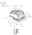
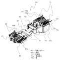
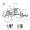
図1は、本発明の実施例に係る電線保持構造1が組み込まれた照明装置の分解斜視図である。図2は、図1に示した電線ホルダー60が取り付けられる前の照明装置200の斜視図である。図3は、図2に示した電線ホルダー取付部110周辺を拡大した図である。図4は、図3に示した電線ホルダー取付部110周辺の上面図である。図5は、図1に示した電線ホルダー60を拡大した図である。図6は、図1に示した電線ホルダー60の上押さえ部70と下押さえ部80とを重ね合わせる前の状態を示した斜視図である。図7は、図4に示した電線ホルダー取付部110に電線ホルダー60が取り付けられた状態を示した上面図である。図8は、図7に示した電線ホルダー60および電線ホルダー取付部110の側面図である。図9は、図7に示した電線ホルダー60および電線ホルダー取付部110のA−A線断面図である。図10は、図7に示した電線ホルダー60および電線ホルダー取付部110のB−B線断面図である。図11は、電線ホルダー60に4本の電線Wをセットする手順を示した図である。
なお、便宜上、図中矢印方向を前後、左右及び上下方向とする。
FIG. 1 is an exploded perspective view of a lighting device in which an electric wire holding structure 1 according to an embodiment of the present invention is incorporated. FIG. 2 is a perspective view of the lighting device 200 before the wire holder 60 shown in FIG. 1 is attached. FIG. 3 is an enlarged view of the periphery of the electric wire holder attaching portion 110 shown in FIG. FIG. 4 is a top view of the periphery of the wire holder mounting portion 110 shown in FIG. FIG. 5 is an enlarged view of the electric wire holder 60 shown in FIG. FIG. 6 is a perspective view showing a state before the upper pressing portion 70 and the lower pressing portion 80 of the electric wire holder 60 shown in FIG. FIG. 7 is a top view showing a state where the electric wire holder 60 is attached to the electric wire holder attaching portion 110 shown in FIG. FIG. 8 is a side view of the wire holder 60 and the wire holder mounting portion 110 shown in FIG. FIG. 9 is a cross-sectional view of the electric wire holder 60 and the electric wire holder attaching portion 110 shown in FIG. FIG. 10 is a cross-sectional view of the electric wire holder 60 and the electric wire holder attaching portion 110 shown in FIG. FIG. 11 is a diagram illustrating a procedure for setting the four electric wires W in the electric wire holder 60.
For the sake of convenience, the arrow directions in the figure are the front and rear, the left and right, and the up and down direction.

本発明の実施例に係る電線保持構造1は、4本の電線Wの一部が整列保持され、4本の電線Wの延在方向に直交する方向の一端側に回動軸72を有してなる電線ホルダー60と、4本の電線Wの各電線Wが圧接される複数の圧接端子32が設けられ、電線ホルダー60が回動軸72を軸支部120によって軸支され、回動されながら取り付けられる電線ホルダー取付部110と、を有してなり、電線ホルダー60が電線ホルダー取付部110に取り付けられた場合、電線ホルダー60と電線ホルダー取付部110とが係合部150によって係合され、4本の電線Wが圧接端子32に圧接されて保持されるものである。
このような電線保持構造1は、例えば、車内の天井に配置される照明装置200に組み込まれる。
この照明装置200は、レンズ10と、照明機能部20と、ハウジング100と、を有してなる。
The electric wire holding structure 1 according to the embodiment of the present invention has a part of four electric wires W aligned and held, and has a rotating shaft 72 on one end side in a direction orthogonal to the extending direction of the four electric wires W. The electric wire holder 60 and a plurality of press contact terminals 32 to which the electric wires W of the four electric wires W are press-contacted are provided, and the electric wire holder 60 is pivotally supported by the pivotal support portion 120 with the pivot shaft 72 being rotated. An electric wire holder attaching portion 110 to be attached. When the electric wire holder 60 is attached to the electric wire holder attaching portion 110, the electric wire holder 60 and the electric wire holder attaching portion 110 are engaged by the engaging portion 150, Four electric wires W are held in pressure contact with the pressure contact terminal 32.
Such an electric wire holding structure 1 is incorporated in the illuminating device 200 arrange | positioned at the ceiling in a vehicle, for example.
The lighting device 200 includes a lens 10, a lighting function unit 20, and a housing 100.

まず、レンズ10について説明する。
レンズ10は、外形が長方形状をなし、光源となるバルブ50から出射された光を集光するものである。
First, the lens 10 will be described.
The lens 10 has a rectangular outer shape and collects light emitted from the bulb 50 serving as a light source.

次に、照明機能部20について説明する。
照明機能部20は、バスバー30と、スイッチ操作部40と、バルブ50と、電線ホルダー60とを有してなる。
Next, the illumination function unit 20 will be described.
The illumination function unit 20 includes a bus bar 30, a switch operation unit 40, a bulb 50, and an electric wire holder 60.

バスバー30は、導電性の金属板状部材が回路形状にプレス加工されてなる配線部材である。このバスバー30は、不図示の溶着ピン等を用いてハウジング100に取り付けられる。
また、バスバー30は、給電端子31および4本の電線Wが圧接される4つの圧接端子32を有してなる。各圧接端子32は、図3および図4に示すように、溝32bが形成された圧接刃32aを有し、この圧接刃32aの溝32b内に電線Wが押し込まれることによって、電線Wの不図示の絶縁被覆部が剥がされ、露出された導体部が圧接刃32aに接続されるようになっている。
なお、この実施例では、電線Wの数が4本であるものを例示したが、電線Wの数は4本に限定されない。また、圧接端子32についてもその数は限定されず、電線Wの数に応じて設けられる。
The bus bar 30 is a wiring member formed by pressing a conductive metal plate member into a circuit shape. The bus bar 30 is attached to the housing 100 using a welding pin (not shown).
In addition, the bus bar 30 includes a power supply terminal 31 and four press contact terminals 32 to which the four electric wires W are press contacted. As shown in FIGS. 3 and 4, each press contact terminal 32 has a press contact blade 32 a in which a groove 32 b is formed. When the wire W is pushed into the groove 32 b of the press contact blade 32 a, The illustrated insulating coating is peeled off, and the exposed conductor is connected to the press contact blade 32a.
In this embodiment, the number of the electric wires W is four, but the number of the electric wires W is not limited to four. Further, the number of the press contact terminals 32 is not limited, and is provided according to the number of the electric wires W.

スイッチ操作部40は、バルブ50の点灯消灯の動作モードを切替え操作するための操作部であり、ハウジング100に取り付けられる。このスイッチ操作部40には、端子であるコンタクト41が組み込まれ、このコンタクト41が給電端子31に接触されることによって、スイッチ操作部40による動作モードに応じたバルブ50への通電操作が行なわれるようになっている。   The switch operation unit 40 is an operation unit for switching the operation mode of turning on / off the bulb 50 and is attached to the housing 100. The switch operation unit 40 incorporates a contact 41 as a terminal. When the contact 41 is brought into contact with the power supply terminal 31, the switch operation unit 40 performs an energization operation to the valve 50 according to the operation mode. It is like that.

電線ホルダー60は、4本の電線Wの一部が整列保持されるものであり、回動されながら電線ホルダー取付部110に取り付けられることによって4本の電線Wが各圧接端子32に同時に圧接されるようになっている。
この電線ホルダー60は、図5および図6に示すように、電線ホルダー60のホルダー上面60aを形成する上押さえ部70と、電線ホルダー60のホルダー底面60bを形成する下押さえ部80とが折り曲げ可能な連結部90を介して連結されている。電線ホルダー60は、この連結部90が折り曲げられることによって上押さえ部70と下押さえ部80とが重ね合わされ、上押さえ部70と下押さえ部80との間に4本の電線Wが挟み込まれるようになっている。
The electric wire holder 60 has a part of the four electric wires W aligned and held, and is attached to the electric wire holder attaching portion 110 while being rotated, so that the four electric wires W are simultaneously pressed into contact with the respective press contact terminals 32. It has become so.
As shown in FIGS. 5 and 6, the electric wire holder 60 can be bent at an upper pressing portion 70 that forms the holder upper surface 60 a of the electric wire holder 60 and a lower pressing portion 80 that forms the holder bottom surface 60 b of the electric wire holder 60. Are connected via a connecting part 90. In the electric wire holder 60, the upper pressing portion 70 and the lower pressing portion 80 are overlapped when the connecting portion 90 is bent, and the four electric wires W are sandwiched between the upper pressing portion 70 and the lower pressing portion 80. It has become.

上押さえ部70は、上押さえ側係合部71と、回動軸72と、上押さえ側電線保持部73とを有してなる。
上押さえ側係合部71は、上押さえ部70が下押さえ部80と重ね合わされた場合、後述する下押さえ側係合部81と係合される部分である。この上押さえ側係合部71は、電線Wの並び方向の上押さえ部70の端部のうち、連結部90が設けられない側の端部70aから突起されてなる係合突部71aを有してなる。
The upper pressing portion 70 includes an upper pressing side engaging portion 71, a rotating shaft 72, and an upper pressing side electric wire holding portion 73.
The upper presser side engaging portion 71 is a portion that is engaged with a lower presser side engaging portion 81 to be described later when the upper presser portion 70 is overlapped with the lower presser portion 80. The upper pressing side engaging portion 71 has an engaging protrusion 71a that protrudes from an end portion 70a on the side where the connecting portion 90 is not provided, of the end portions of the upper pressing portion 70 in the arrangement direction of the wires W. Do it.

回動軸72は、上押さえ部70の電線Wの並び方向の端部のうち、連結部が設けられない側の端部70a近傍の両側部から突出されてなる。この回動軸72は、断面が半円形状の柱状をなしている。   The rotating shaft 72 protrudes from both side portions in the vicinity of the end portion 70a on the side where the connecting portion is not provided, of the end portions of the upper pressing portion 70 in the arrangement direction of the electric wires W. The rotating shaft 72 has a columnar shape with a semicircular cross section.

上押さえ側電線保持部73は、4本の電線Wの一部が整列保持される部分であり、各電線Wが嵌め込まれる4つの電線保持溝73aを有してなる。   The upper holding side electric wire holding portion 73 is a portion in which a part of the four electric wires W is aligned and held, and has four electric wire holding grooves 73a into which the electric wires W are fitted.

下押さえ部80は、下押さえ側係合部81と、圧接刃貫通部82と、下押さえ側電線保持部83とを有してなる。
下押さえ側係合部81は、上押さえ部70が下押さえ部80と重ね合わされた場合、上押さえ部側係合部71と係合される部分である。この下押さえ側係合部81は、電線Wの並び方向の下押さえ部80の端部のうち、連結部90が設けらない側の端部80a位置で上押さえ部70との重ね合わせ面80bに片状に立設された係合片部81aと、この係合片部81aに形成された貫通孔である係合孔81bとを有してなる。
The lower pressing portion 80 includes a lower pressing side engaging portion 81, a press contact blade penetrating portion 82, and a lower pressing side electric wire holding portion 83.
The lower presser side engaging portion 81 is a portion that is engaged with the upper presser portion engaging portion 71 when the upper presser portion 70 is overlapped with the lower presser portion 80. The lower pressing side engaging portion 81 has an overlapping surface 80b with the upper pressing portion 70 at the position of the end portion 80a on the side where the connecting portion 90 is not provided among the end portions of the lower pressing portion 80 in the arrangement direction of the wires W. The engagement piece portion 81a is provided in the shape of a piece, and the engagement hole 81b is a through hole formed in the engagement piece portion 81a.

圧接刃貫通部82は、圧接刃32aが下押さえ部80を貫通されるため下押さえ部80に形成された貫通孔である。   The press contact blade penetrating portion 82 is a through hole formed in the lower presser portion 80 because the press contact blade 32 a is passed through the lower presser portion 80.

下押さえ側電線保持部83は、上押さえ部70と下押さえ部80とが4本の電線Wを間に挟むようにして重ね合わされた場合、4本の電線Wの整列状態を維持しながら、各電線Wを上押さえ部70の各電線保持溝73a内に押し込む部分である。   When the upper presser portion 70 and the lower presser portion 80 are overlapped with the four electric wires W sandwiched therebetween, the lower presser-side electric wire holding portion 83 maintains the aligned state of the four electric wires W while maintaining the aligned state of the four electric wires W. This is a portion where W is pushed into each wire holding groove 73 a of the upper pressing portion 70.

また、電線ホルダー60は、後述する係合壁部126が挿通可能に形成された係合用貫通孔61が形成されており、この係合用貫通孔61内で電線ホルダー60に設けられた係合凸部151と、電線ホルダー取付部110に設けられた係合孔部152とが係合されることによって電線ホルダー取付部110に固定されるようになっている。   Further, the electric wire holder 60 is formed with an engaging through hole 61 in which an engaging wall portion 126 to be described later can be inserted, and the engaging protrusion provided in the electric wire holder 60 in the engaging through hole 61. The portion 151 and the engagement hole portion 152 provided in the electric wire holder attachment portion 110 are engaged with each other so as to be fixed to the electric wire holder attachment portion 110.

このような電線ホルダー60に4本の電線Wをセットする場合、図11に示すように、電線ホルダー60を固定するとともに各電線Wの位置および張力を調整するための電線セット補助冶具300を用いる。作業者は、電線ホルダー60を電線セット補助冶具300にセットし(図11(a))、上押さえ部70の各電線保持溝73aの溝入口に各電線Wを配置し(図11(b))、連結部90を折り曲げ、下押さえ部80を上押さえ部70に重ね合わせる(図11(c))ことによって電線ホルダー60に4本の電線Wがセットされる。   When four electric wires W are set in such an electric wire holder 60, as shown in FIG. 11, the electric wire set auxiliary jig 300 for fixing the electric wire holder 60 and adjusting the position and tension of each electric wire W is used. . The operator sets the electric wire holder 60 on the electric wire setting auxiliary jig 300 (FIG. 11A), and arranges the electric wires W at the groove entrances of the electric wire holding grooves 73a of the upper pressing portion 70 (FIG. 11B). ), The four electric wires W are set in the electric wire holder 60 by bending the connecting portion 90 and superimposing the lower pressing portion 80 on the upper pressing portion 70 (FIG. 11C).

次に、ハウジング100について説明する。
ハウジング100は、照明装置200の基部として、レンズ10および照明機能部20が取り付けられる。
このハウジング100は、電線ホルダー60が取り付けられる電線ホルダー取付部を有してなる。
Next, the housing 100 will be described.
The housing 100 is attached with the lens 10 and the illumination function unit 20 as a base of the illumination device 200.
The housing 100 includes an electric wire holder attaching portion to which the electric wire holder 60 is attached.

電線ホルダー取付部110は、4本の電線Wの各電線Wが圧接される4つの圧接端子32が設けられ、電線ホルダー60が回動軸を軸支部120によって軸支され、回動されながら取り付けられる部分であり、電線ホルダー60が電線ホルダー取付部110に取り付けられた場合、4本の電線Wが圧接端子32に圧接されて保持されるようになっている。   The electric wire holder mounting portion 110 is provided with four press contact terminals 32 to which the electric wires W of the four electric wires W are pressed, and the electric wire holder 60 is pivotally supported by the pivotal support portion 120 and attached while being rotated. When the electric wire holder 60 is attached to the electric wire holder attaching portion 110, the four electric wires W are pressed against and held by the press contact terminals 32.

各軸支部120は、電線ホルダー60が取り付けされる取付面110aに立設された壁からなる軸受け壁部121と、回動軸72が上方から挿入可能に形成された溝からなる軸受け溝部122と、電線ホルダー60の上方への移動を規制するように電線ホルダー60に当接され、回動軸72が軸受け溝部122からの抜け出すことを防止する軸抜け防止用当接面130と、電線ホルダー60が取り付けされる取付面110aに立設され、後述する係合孔部152が形成される係合壁部126と、を有してなる。   Each of the shaft support portions 120 includes a bearing wall portion 121 made of a wall erected on the attachment surface 110a to which the electric wire holder 60 is attached, and a bearing groove portion 122 made of a groove in which the rotation shaft 72 can be inserted from above. A contact surface 130 for preventing shaft disengagement that is brought into contact with the wire holder 60 so as to restrict the upward movement of the wire holder 60 and prevents the rotating shaft 72 from coming out of the bearing groove portion 122; And an engaging wall portion 126 in which an engaging hole portion 152 to be described later is formed.

軸受け溝部121は、図8に示すように、溝入口側から溝内に向けて溝幅が小さい部分から大きい部分に変化されるように幅小溝部123および幅大溝部124を有してなる。
幅小溝部123は、断面半円の柱状である回動軸の半径とほぼ等しい溝幅をなす部分である。このような幅小溝部123によって、回動軸72が断面半円形状の直線部分72aを溝の内縁に向けて挿入されるようになっている。
幅大溝部124は、幅小溝部123の下端に水平方向の段差面124aを形成するように溝の終端部まで溝幅が拡大された部分である。このような幅大溝部124によって、回動軸72が、溝の終端部で断面半円形状の直線部分72aを上方に向ける向きに回動されるようになっている。
As shown in FIG. 8, the bearing groove 121 has a narrow groove 123 and a wide groove 124 so that the groove width is changed from a small portion to a large portion from the groove entrance side into the groove.
The small-width groove portion 123 is a portion having a groove width substantially equal to the radius of the rotation shaft that is a columnar shape with a semicircular cross section. By such a narrow groove portion 123, the rotation shaft 72 is inserted so that the straight portion 72a having a semicircular cross section is directed toward the inner edge of the groove.
The wide groove portion 124 is a portion in which the groove width is expanded to the end portion of the groove so as to form a horizontal step surface 124 a at the lower end of the small groove portion 123. By such a wide groove portion 124, the rotation shaft 72 is rotated in a direction in which the straight portion 72a having a semicircular cross section is directed upward at the end portion of the groove.

軸抜け防止用当接面130は、上部迫出し壁125の下面125aと、上述した軸受け溝部122の段差面124aとを有してなる。
上部迫出し壁125は、電線ホルダー60のホルダー上面60aの上方に迫出すように設けられた壁であり、電線ホルダー60が取付完了位置から上方に移動された場合、上部迫出し壁125の下面125aがホルダー上面60aに当接されるようになっている。
The shaft slip-off preventing contact surface 130 includes a lower surface 125a of the upper protruding wall 125 and a step surface 124a of the bearing groove portion 122 described above.
The upper pressing wall 125 is a wall provided so as to protrude above the holder upper surface 60 a of the electric wire holder 60, and when the electric wire holder 60 is moved upward from the installation completion position, the lower surface of the upper pressing wall 125. 125a is brought into contact with the holder upper surface 60a.

軸受け溝部122の段差面124aは、電線ホルダー60が上方への移動された場合、回動軸72の直線部分72aを形成する面72bに当接されるようになっている。   The stepped surface 124 a of the bearing groove 122 is brought into contact with a surface 72 b that forms the linear portion 72 a of the rotating shaft 72 when the electric wire holder 60 is moved upward.

また、電線ホルダー取付部110は、電線ホルダー60を保持する一対の電線ホルダー保持壁140を有してなる。
一対の電線ホルダー保持壁140は、電線ホルダー60が回動されながら電線ホルダー取付部110に取り付けられる場合、各電線Wが電線ホルダー60の両側部60c位置で上方に屈曲されるように各電線Wに当接され、4本の電線Wの上方に屈曲された部分W1とともに電線ホルダー60を側方から挟み込むことによって電線ホルダー60を保持するものである。
In addition, the electric wire holder mounting portion 110 includes a pair of electric wire holder holding walls 140 that hold the electric wire holder 60.
When the electric wire holder 60 is attached to the electric wire holder attaching portion 110 while the electric wire holder 60 is rotated, the electric wire W holding walls 140 are arranged so that the electric wires W are bent upward at the positions of both side portions 60c of the electric wire holder 60. The electric wire holder 60 is held by sandwiching the electric wire holder 60 from the side together with the portion W1 bent above the four electric wires W.

各電線ホルダー保持壁140は、外形矩形状をなし、前後方向の幅が、図8に示すように、電線ホルダー60が電線ホルダー取付部110に取り付けられた状態で、電線ホルダー60によって保持された部分の電線Wが電線ホルダー保持壁140の面内に収まるように設定されている。
また、各電線ホルダー保持壁140は、その高さが、電線ホルダー60が電線ホルダー取付部110に取り付けられた状態で、上端が電線ホルダー60によって保持された部分の電線Wに比して上方に位置するように設定されている。
さらに、各電線ホルダー保持壁140は、各電線ホルダー保持壁140と電線ホルダー60の側部60cとの間隔が、図10に示すように、電線Wの直径と略等しくなるように設定されている。
Each electric wire holder holding wall 140 has a rectangular outer shape, and the width in the front-rear direction is held by the electric wire holder 60 in a state where the electric wire holder 60 is attached to the electric wire holder attaching portion 110 as shown in FIG. The portion of the electric wire W is set so as to be within the plane of the electric wire holder holding wall 140.
Each of the electric wire holder holding walls 140 has a height higher than that of the portion of the electric wire W held by the electric wire holder 60 when the electric wire holder 60 is attached to the electric wire holder attaching portion 110. It is set to be located.
Furthermore, each wire holder holding wall 140 is set so that the distance between each wire holder holding wall 140 and the side portion 60c of the wire holder 60 is substantially equal to the diameter of the wire W as shown in FIG. .

次に、係合部150について説明する。
係合部150は、電線ホルダー60と電線ホルダー取付部110とが、電線ホルダー60に設けられた係合凸部151と、電線ホルダー取付部110に設けられた係合孔部152とで、電線ホルダー60の取付完了位置にて係合されるものである。
Next, the engaging part 150 will be described.
The engaging portion 150 includes an electric wire holder 60 and an electric wire holder attaching portion 110, an engaging convex portion 151 provided in the electric wire holder 60, and an engaging hole portion 152 provided in the electric wire holder attaching portion 110. The holder 60 is engaged at the attachment completion position.

係合凸部151は、弾性係合片部151aから突起された部分である。弾性係合片部151aは、係合用貫通孔61の孔縁、かつ上押さえ部70の重ね合わせ面70bから片状に突出され、係合用貫通孔61内でU字状に屈曲されてなる。
係合孔部152は、係合壁部126が水平方向に貫通されるように形成されてなる。
The engagement convex portion 151 is a portion protruding from the elastic engagement piece portion 151a. The elastic engagement piece portion 151 a protrudes in a piece shape from the hole edge of the engagement through hole 61 and the overlapping surface 70 b of the upper pressing portion 70, and is bent in a U shape within the engagement through hole 61.
The engagement hole 152 is formed so that the engagement wall 126 penetrates in the horizontal direction.

ここで、図12−図15を用いて、電線ホルダー60を電線ホルダー取付部110に取り付ける手順を説明する。図12および図13は、電線ホルダー60を電線ホルダー取付部110に取り付ける手順を示した図である。図14は、図7に示した電線ホルダー60および電線ホルダー取付部110のA−A線断面図であり、電線Wが一対の電線ホルダー保持壁140に当接される前の状態を説明するための図である。図15は、図7に示した電線ホルダー60および電線ホルダー取付部110のA−A線断面図であり、電線ホルダー60が電線ホルダー取付部110に取り付け完了された状態を説明するための図である。
まず、作業者は、電線ホルダー60の回動軸72を、各軸支部120に取り付ける(図12(a)参照)。この状態では、電線ホルダー60から導出される各電線Wは、図14に示すように、屈曲されていない。
また、回動軸72が軸受け溝部122の入り口から挿入されて軸支部120に取り付けられる場合、回動軸72が直線部分72aを溝の内縁に向けて挿入される。このため、電線ホルダー60の向きが定まり、電線ホルダー60の誤組み付けが防止される。
Here, the procedure for attaching the electric wire holder 60 to the electric wire holder attaching portion 110 will be described with reference to FIGS. 12 and 13 are diagrams showing a procedure for attaching the electric wire holder 60 to the electric wire holder attaching portion 110. FIG. FIG. 14 is a cross-sectional view of the electric wire holder 60 and the electric wire holder attaching portion 110 shown in FIG. 7 taken along the line AA, for explaining a state before the electric wires W are brought into contact with the pair of electric wire holder holding walls 140. FIG. 15 is a cross-sectional view taken along line AA of the electric wire holder 60 and the electric wire holder attaching portion 110 shown in FIG. 7, and is a view for explaining a state in which the electric wire holder 60 is completely attached to the electric wire holder attaching portion 110. is there.
First, the operator attaches the rotation shaft 72 of the electric wire holder 60 to each shaft support portion 120 (see FIG. 12A). In this state, each electric wire W led out from the electric wire holder 60 is not bent as shown in FIG.
When the rotation shaft 72 is inserted from the entrance of the bearing groove 122 and attached to the shaft support portion 120, the rotation shaft 72 is inserted with the straight portion 72a facing the inner edge of the groove. For this reason, the direction of the electric wire holder 60 is determined, and erroneous assembly of the electric wire holder 60 is prevented.

その後、作業者は、回動軸72を中心として、電線ホルダー60を回動させる(図12(b)参照)。このとき、電線ホルダー60が回動されるとともに、4本の電線Wが各圧接刃32aに近づけられる。また、電線ホルダー60は、電線ホルダー60の両側部60cから導出される4本の電線Wが、一対の電線ホルダー保持壁140に当接開始され、各電線Wが上方に屈曲されるように回動される。
この電線ホルダー60の回動の途中で、電線Wが、一対の電線ホルダー保持壁140に接触されると、一対の電線ホルダー保持壁140からの反力により電線ホルダー60が上方へ移動され、回動軸72の面72bが段差面124aに当接される。このような場合、段差面124aが梃子の原理における支点になって電線ホルダー60が回動される。
Thereafter, the worker rotates the electric wire holder 60 around the rotation shaft 72 (see FIG. 12B). At this time, the electric wire holder 60 is rotated, and the four electric wires W are brought close to the press contact blades 32a. In addition, the electric wire holder 60 is rotated so that the four electric wires W led out from the both side portions 60c of the electric wire holder 60 start to contact the pair of electric wire holder holding walls 140 and each electric wire W is bent upward. Moved.
When the electric wire W comes into contact with the pair of electric wire holder holding walls 140 in the middle of the rotation of the electric wire holder 60, the electric wire holder 60 is moved upward by the reaction force from the pair of electric wire holder holding walls 140. The surface 72b of the moving shaft 72 is brought into contact with the step surface 124a. In such a case, the stepped surface 124a becomes a fulcrum in the lever principle and the electric wire holder 60 is rotated.

その後、作業者は、さらに電線ホルダー60を回動させることによって、各電線Wが各圧接端子32に圧接開始される(図12(c)参照)。このとき、電線Wが圧接刃32aに接触されると、電線Wを切ろうとする力の反力により電線ホルダー60が上方へ移動され、回動軸72の面72bが段差面124aに当接される。このため、段差面124aが梃子の原理における支点となり、電線Wを支点に近づけて容易に圧接することができる。   Thereafter, the operator further rotates the electric wire holder 60, whereby each electric wire W starts to be pressed against each press contact terminal 32 (see FIG. 12C). At this time, when the electric wire W comes into contact with the press contact blade 32a, the electric wire holder 60 is moved upward by the reaction force of the force for cutting the electric wire W, and the surface 72b of the rotating shaft 72 is brought into contact with the step surface 124a. The For this reason, the step surface 124a becomes a fulcrum in the principle of the insulator, and the electric wire W can be brought close to the fulcrum and can be easily pressed.

その後、作業者は、さらに電線ホルダー60を回動させ、電線ホルダー60と電線ホルダー取付部110とを係合部150によって係合することによって、電線ホルダー60が電線ホルダー取付部110に取り付け完了される(図12(d)参照)。電線ホルダー60が電線ホルダー取付部110に取り付け完了されると、電線ホルダー60は、図15に示すように、上方に屈曲された電線Wとともに一対の電線ホルダー保持壁140によって両側部60c側から保持される。また、電線ホルダー60の両側部60cから導出された各電線Wは上方に向けて屈曲された状態で保持される。すなわち、各電線Wは、ストレインリリーフ構造になるため、各電線Wに引っ張り力が作用しても、その引っ張り力が圧接箇所に直接作用しないようになっている。   Thereafter, the operator further rotates the electric wire holder 60 and engages the electric wire holder 60 and the electric wire holder attaching portion 110 with the engaging portion 150, whereby the electric wire holder 60 is completely attached to the electric wire holder attaching portion 110. (See FIG. 12D). When the electric wire holder 60 is completely attached to the electric wire holder attaching portion 110, the electric wire holder 60 is held from the side portions 60c side by the pair of electric wire holder holding walls 140 together with the electric wires W bent upward as shown in FIG. Is done. Each electric wire W led out from both side portions 60c of the electric wire holder 60 is held in a state bent upward. That is, since each electric wire W has a strain relief structure, even if a tensile force acts on each electric wire W, the tensile force does not directly act on the press contact portion.

本発明の実施例に係る電線保持構造1は、電線ホルダー60が軸支部120によって軸支され、回動されながら4本の電線Wを圧接端子32に圧接させ、しかもストレインリリーフ構造を適用し、一対の電線ホルダー保持壁140が4本の電線Wの上方に屈曲された部分W1とともに電線ホルダー60を側方から挟み込み、電線ホルダー60を保持することによって、電線ホルダー60のガタつきを抑えるようになっているので、4本の電線Wを圧接端子32に圧接する際に必要な荷重を小さく抑えるとともに、電線Wと圧接端子32との接続安定性が低下することを防ぐことができる。   In the electric wire holding structure 1 according to the embodiment of the present invention, the electric wire holder 60 is pivotally supported by the pivotal support portion 120, the four electric wires W are pressed against the press contact terminals 32 while being rotated, and a strain relief structure is applied. The pair of electric wire holder holding walls 140 sandwich the electric wire holder 60 from the side together with the portion W1 bent upward of the four electric wires W, and hold the electric wire holder 60 so that the play of the electric wire holder 60 is suppressed. Therefore, it is possible to suppress a load required when the four electric wires W are press-contacted to the press contact terminal 32 and to prevent the connection stability between the electric wire W and the press contact terminal 32 from being lowered.

また、本発明の実施例に係る電線保持構造1は、電線ホルダー60の回動の途中で、電線Wが、一対の電線ホルダー保持壁140に接触され、反力により電線ホルダー60が上方へ移動された場合、回動軸72の直線部分72aを形成する面72bが段差面124aに当接され、段差面124aが梃子の原理における支点になって電線ホルダー60が回動されるので、電線ホルダー60が一対の電線ホルダー保持壁140との間に4本の電線を位置させた状態で回動された場合であっても、回転の際に必要な荷重を小さく抑えることがことできる。   Further, in the electric wire holding structure 1 according to the embodiment of the present invention, the electric wire W is brought into contact with the pair of electric wire holder holding walls 140 during the rotation of the electric wire holder 60, and the electric wire holder 60 moves upward by a reaction force. In this case, the surface 72b forming the linear portion 72a of the rotating shaft 72 is brought into contact with the step surface 124a, and the step surface 124a serves as a fulcrum in the lever principle, so that the wire holder 60 is rotated. Even when 60 is rotated in a state where four electric wires are positioned between the pair of electric wire holder holding walls 140, a load necessary for rotation can be kept small.

なお、本発明の実施例に係る電線保持構造1は、各電線ホルダー保持壁140が外形矩形状をなすものを例示したが、これに限らず、電線ホルダー60が回動されながら取り付けられる場合、複数の電線Wが上方に屈曲されるように複数の電線Wに当接され、電線ホルダー60が取り付け完了された場合、複数の電線Wとともに電線ホルダー60を側方から挟み込むようになっていればその他の形状であっても構わない。   In addition, although the electric wire holding structure 1 which concerns on the Example of this invention illustrated what each electric wire holder holding wall 140 makes an external shape rectangular shape, when not only this but the electric wire holder 60 is attached while rotating, If the plurality of wires W are brought into contact with the plurality of wires W so as to be bent upward and the wire holder 60 is completely attached, the wire holder 60 is sandwiched from the side together with the plurality of wires W. Other shapes may be used.

また、本発明の実施例に係る電線保持構造1は、回動軸72が断面半円形状であるものを例示したが、これに限らず、断面円状であっても構わない。   Moreover, although the electric wire holding structure 1 which concerns on the Example of this invention illustrated what the rotation axis | shaft 72 has a semicircular cross section, not only this but a cross-sectional circle shape may be sufficient.

以上、本発明者によってなされた発明を、上述した発明の実施例に基づき具体的に説明したが、本発明は、上述した発明の実施例に限定されるものではなく、その要旨を逸脱しない範囲において種々変更可能である。   The invention made by the present inventor has been specifically described based on the above-described embodiments of the invention. However, the present invention is not limited to the above-described embodiments of the invention and does not depart from the gist thereof. Various changes can be made.

1 電線保持構造
10 レンズ
20 照明機能部
30 バスバー
31 給電端子
32 圧接端子
32a 圧接刃
32b 溝
40 スイッチ操作部
41 コンタクト
50 バルブ
60 電線ホルダー
60a ホルダー上面
60b ホルダー底面
60c 側部
61 係合用貫通孔
70 上押さえ部
70a 端部
70b 重な合わせ面
71 上押さえ側係合部
71a 係合突部
72 回動軸
72a 直線部分
72b 面
73 上押さえ側電線保持部
73a 電線保持溝
80 下押さえ部
80a 端部
80b 重ね合わせ面
81 下押さえ側係合部
81a 係合片部
81b 係合孔
82 圧接刃貫通部
83 下押さえ側電線保持部
90 連結部
100 ハウジング
110 電線ホルダー取付部
110a 取付面
120 軸支部
121 軸受け壁部
122 軸受け溝部
123 幅小溝部
124 幅大溝部
124a 段差面
125 上部迫出し壁
125a 下面
126 係合壁部
130 軸抜け防止用当接面
140 電線ホルダー保持壁
150 係合部
151 係合凸部
151a 弾性係合片
152 係合孔部
200 照明装置
300 電線セット補助冶具
W 電線
W1 上方に屈曲された部分
DESCRIPTION OF SYMBOLS 1 Electric wire holding | maintenance structure 10 Lens 20 Illumination function part 30 Bus bar 31 Feed terminal 32 Press contact terminal 32a Press contact blade 32b Groove 40 Switch operation part 41 Contact 50 Valve 60 Electric wire holder 60a Holder upper surface 60b Holder bottom surface 60c Side part 61 On through hole 70 for engagement Holding portion 70a End portion 70b Overlapping mating surface 71 Upper holding side engaging portion 71a Engaging projection 72 Turning shaft 72a Linear portion 72b Surface 73 Upper holding side electric wire holding portion 73a Electric wire holding groove 80 Lower holding portion 80a End portion 80b Overlapping surface 81 Lower pressing side engaging portion 81a Engaging piece portion 81b Engaging hole 82 Press-contact blade penetrating portion 83 Lower pressing side electric wire holding portion 90 Connecting portion 100 Housing 110 Electric wire holder mounting portion 110a Mounting surface 120 Shaft support portion 121 Bearing wall Part 122 bearing groove part 123 narrow groove 124 Wide groove portion 124a Stepped surface 125 Upper protruding wall 125a Lower surface 126 Engaging wall portion 130 Contact surface for preventing shaft slippage 140 Electric wire holder holding wall 150 Engaging portion 151 Engaging convex portion 151a Elastic engaging piece 152 Engaging hole Part 200 Illuminating device 300 Electric wire set auxiliary jig W Electric wire W1 Bent upward

Claims (2)

複数の電線の一部が整列保持され、前記複数の電線の延在方向に直交する方向の一端側に回動軸を有してなる電線ホルダーと、前記複数の電線の各電線が圧接される複数の圧接端子が設けられ、前記電線ホルダーが前記回動軸を軸支部によって軸支され、回動されながら取り付けられる電線ホルダー取付部と、を有してなり、前記電線ホルダーが前記電線ホルダー取付部に取り付けられた場合、前記複数の電線が前記圧接端子に圧接されて保持される電線保持構造において、
前記電線ホルダー取付部は、
前記電線ホルダーが回動されながら取り付けられる場合、前記各電線が前記電線ホルダーの両側部位置で上方に屈曲されるように各電線に当接され、前記複数の電線の上方に屈曲された部分とともに前記電線ホルダーを側方から挟み込むことによって前記電線ホルダーを保持する一対の電線ホルダー保持壁
を有してなることを特徴とする電線保持構造。
A part of the plurality of electric wires is aligned and held, and an electric wire holder having a rotating shaft on one end side in a direction orthogonal to the extending direction of the plurality of electric wires, and each electric wire of the plurality of electric wires are press-contacted A plurality of press contact terminals, and the wire holder is pivotally supported by the pivot support portion and attached while being rotated, and the wire holder is attached to the wire holder. In the electric wire holding structure in which the plurality of electric wires are held in pressure contact with the press contact terminals when attached to the part,
The wire holder mounting portion is
When the electric wire holder is attached while being rotated, the electric wires are brought into contact with the electric wires so that the electric wires are bent upward at both side positions of the electric wire holder, together with the bent portions of the plurality of electric wires. An electric wire holding structure comprising a pair of electric wire holder holding walls for holding the electric wire holder by sandwiching the electric wire holder from the side.
前記回動軸は、
断面半円形状をなし、
前記軸支部は、
前記回動軸が上方から挿入可能に形成された溝からなり、かつ前記回動軸が断面半円形状の直線部分を溝の内縁に向けて挿入されるように溝幅が設定されてなる幅小溝部と、前記幅小溝部の下端に水平方向の段差面を形成するように溝幅が拡大され、溝の底で前記回動軸が前記直線部分を上方に向けるように回動される幅大溝部と、を含む軸受け溝部
を有してなり、
前記段差面は、
前記電線ホルダーが回動の途中で上方へ移動された場合、前記回動軸の直線部分を形成する面に当接されること
を特徴とする請求項1に記載の電線保持構造。
The pivot axis is
It has a semicircular cross section,
The shaft support is
The width formed by the groove formed so that the rotating shaft is formed so as to be insertable from above, and the rotating shaft is inserted with the straight portion having a semicircular cross section facing the inner edge of the groove. The groove width is widened so that a horizontal step surface is formed at the lower end of the small groove portion and the width of the small groove portion, and the width at which the rotation shaft is rotated so that the linear portion is directed upward at the bottom of the groove A bearing groove including a large groove,
The step surface is
The wire holding structure according to claim 1, wherein when the wire holder is moved upward in the middle of rotation, the wire holder is brought into contact with a surface forming a linear portion of the rotation shaft.
JP2012067130A 2012-03-23 2012-03-23 Electric wire holding structure Pending JP2013200957A (en)

Priority Applications (6)

Application Number Priority Date Filing Date Title
JP2012067130A JP2013200957A (en) 2012-03-23 2012-03-23 Electric wire holding structure
PCT/JP2013/059160 WO2013141408A1 (en) 2012-03-23 2013-03-21 Electric wire holding structure
KR20147026637A KR20140127902A (en) 2012-03-23 2013-03-21 Electric wire holding structure
DE112013001705.9T DE112013001705T5 (en) 2012-03-23 2013-03-21 Support structure for electrical wires
US14/387,324 US20150075865A1 (en) 2012-03-23 2013-03-21 Electric Wire Holding Structure
CN201380016142.0A CN104247155A (en) 2012-03-23 2013-03-21 Electric wire holding structure

Applications Claiming Priority (1)

Application Number Priority Date Filing Date Title
JP2012067130A JP2013200957A (en) 2012-03-23 2012-03-23 Electric wire holding structure

Publications (1)

Publication Number Publication Date
JP2013200957A true JP2013200957A (en) 2013-10-03

Family

ID=48087662

Family Applications (1)

Application Number Title Priority Date Filing Date
JP2012067130A Pending JP2013200957A (en) 2012-03-23 2012-03-23 Electric wire holding structure

Country Status (6)

Country Link
US (1) US20150075865A1 (en)
JP (1) JP2013200957A (en)
KR (1) KR20140127902A (en)
CN (1) CN104247155A (en)
DE (1) DE112013001705T5 (en)
WO (1) WO2013141408A1 (en)

Family Cites Families (5)

* Cited by examiner, † Cited by third party
Publication number Priority date Publication date Assignee Title
JP2004362817A (en) * 2003-06-02 2004-12-24 Fujikura Ltd Insulation displacement connector
JP4830770B2 (en) * 2006-10-06 2011-12-07 住友電装株式会社 Wire holder
US8262373B2 (en) * 2008-02-07 2012-09-11 Emerson Climate Technologies, Inc. Compressor having wire retainer
JP2011113802A (en) 2009-11-26 2011-06-09 Yazaki Corp Connector and wire harness connection structure in vehicle
JP2012038714A (en) * 2010-07-14 2012-02-23 Yazaki Corp Pressure-welding connection apparatus and lighting device

Also Published As

Publication number Publication date
DE112013001705T5 (en) 2014-12-11
KR20140127902A (en) 2014-11-04
US20150075865A1 (en) 2015-03-19
WO2013141408A1 (en) 2013-09-26
CN104247155A (en) 2014-12-24

Similar Documents

Publication Publication Date Title
JP6444775B2 (en) connector
JP5711542B2 (en) Board connection terminal and circuit board holding structure
JP2010184648A (en) Light emitter and wire harness
JP5182384B2 (en) Electrical connector
KR20130095306A (en) Connection structure and connection unit of electronic component
JP2009254073A (en) Assembling structure of bus bar
JP2015043291A (en) Battery direct-mounting fusible link
US8192225B2 (en) Press-contact connection apparatus and illumination apparatus
JP2013200957A (en) Electric wire holding structure
JP2018206545A (en) Crimp terminal
WO2016079835A1 (en) Electrical connection box and board connector
US20120031668A1 (en) Press-contact connection apparatus and illumination apparatus
JP2014093120A (en) Pressure contacting contact and connector
JP2013191405A (en) Electric wire holding structure
JP2012205484A (en) Electric wire wiring method and electric wire wiring tool used for the same
KR20140124849A (en) Jig for setting electric wires
JP4911712B2 (en) Electrical connector assembly
JP5478191B2 (en) Switch device
WO2014112319A1 (en) Bus bar attachment structure and method for manufacturing bus bar attachment structure
JP2008140727A (en) Wiring tool for led, led pressure bonding unit, and wiring unit with led
JP2014232694A (en) Connection structure of wire and pressure-welding terminal
JP2017084751A (en) Coaxial cable connector, coaxial cable connector with carrier and manufacturing method of coaxial cable connector
JP2014127254A (en) Connection structure of electric wire and pressure contact terminal
JP2019021649A (en) connector
JP2013222568A (en) Press contact blade terminal connector