JP2013200944A - Light source device - Google Patents

Light source device Download PDF

Info

Publication number
JP2013200944A
JP2013200944A JP2012066778A JP2012066778A JP2013200944A JP 2013200944 A JP2013200944 A JP 2013200944A JP 2012066778 A JP2012066778 A JP 2012066778A JP 2012066778 A JP2012066778 A JP 2012066778A JP 2013200944 A JP2013200944 A JP 2013200944A
Authority
JP
Japan
Prior art keywords
cooling
light source
unit
source device
detection electrode
Prior art date
Legal status (The legal status is an assumption and is not a legal conclusion. Google has not performed a legal analysis and makes no representation as to the accuracy of the status listed.)
Pending
Application number
JP2012066778A
Other languages
Japanese (ja)
Inventor
Tatsuaki Ishikawa
達章 石川
Current Assignee (The listed assignees may be inaccurate. Google has not performed a legal analysis and makes no representation or warranty as to the accuracy of the list.)
Toshiba Lighting and Technology Corp
Original Assignee
Harison Toshiba Lighting Corp
Priority date (The priority date is an assumption and is not a legal conclusion. Google has not performed a legal analysis and makes no representation as to the accuracy of the date listed.)
Filing date
Publication date
Application filed by Harison Toshiba Lighting Corp filed Critical Harison Toshiba Lighting Corp
Priority to JP2012066778A priority Critical patent/JP2013200944A/en
Publication of JP2013200944A publication Critical patent/JP2013200944A/en
Pending legal-status Critical Current

Links

Images

Classifications

    • YGENERAL TAGGING OF NEW TECHNOLOGICAL DEVELOPMENTS; GENERAL TAGGING OF CROSS-SECTIONAL TECHNOLOGIES SPANNING OVER SEVERAL SECTIONS OF THE IPC; TECHNICAL SUBJECTS COVERED BY FORMER USPC CROSS-REFERENCE ART COLLECTIONS [XRACs] AND DIGESTS
    • Y02TECHNOLOGIES OR APPLICATIONS FOR MITIGATION OR ADAPTATION AGAINST CLIMATE CHANGE
    • Y02BCLIMATE CHANGE MITIGATION TECHNOLOGIES RELATED TO BUILDINGS, e.g. HOUSING, HOUSE APPLIANCES OR RELATED END-USER APPLICATIONS
    • Y02B20/00Energy efficient lighting technologies, e.g. halogen lamps or gas discharge lamps
    • Y02B20/40Control techniques providing energy savings, e.g. smart controller or presence detection

Abstract

PROBLEM TO BE SOLVED: To provide a light source device capable of detecting leakage of a coolant from a cooling system for cooling the light source device and preventing damage to a light source and a power source due to adhesion of the coolant.SOLUTION: A light source device includes: a conductive cooling section 1 capable of internally circulating coolant; irradiation sections 21a, 21b connected at the outside of the cooling section 1 so as to be cooled with the coolant; a detection electrode 41 arranged at a position electrically insulated against the cooling section 1 and at a position where the coolant can be crosslinked between the cooling section 1 and the detection electrode 41 when the coolant leaks from the cooling section 1; and a detection section 51 for detecting electric characteristics between the detection electrode 41 and the cooling section 1, and detecting leakage by means of the changes in the electric characteristics.

Description

本発明の実施形態は、光源装置に関する。   Embodiments described herein relate generally to a light source device.

例えば、液晶や半導体等の製造プロセス、流体の殺菌や光反応処理、照明、
光化学反応等に用いる光源装置は、大光量化が要求されている。大光量を得るには、大電力を投入し光源を点灯する必要があるが、光源や電源から発生する熱の影響により、光源装置の変換効率が低下したり、寿命が短くなる課題がある。
For example, liquid crystal and semiconductor manufacturing processes, fluid sterilization and photoreaction processing, lighting,
A light source device used for a photochemical reaction or the like is required to increase the amount of light. In order to obtain a large amount of light, it is necessary to turn on the light source by turning on a large amount of power. However, there is a problem that the conversion efficiency of the light source device is lowered or the life is shortened due to the influence of heat generated from the light source or the power source.

この種の光源装置では、冷却液を使用した液冷式の冷却システムを使用して、光源や電源からの発熱を低減し、高効率化及び長寿命化を図っている。しかし、光源装置の製造不具合や部品の劣化により、冷却システムから冷却液が液漏れすると、例えば、光源または電源に冷却液が付着して電気的短絡を起こし、光源や電源を破損させる恐れがあり、安全性確保のため、液漏れを的確に検出する必要がある。   In this type of light source device, a liquid cooling type cooling system using a cooling liquid is used to reduce heat generation from the light source and the power source, thereby achieving higher efficiency and longer life. However, if the coolant leaks from the cooling system due to a manufacturing failure of the light source device or deterioration of parts, for example, the coolant may adhere to the light source or the power source, causing an electrical short circuit, which may damage the light source or the power source. In order to ensure safety, it is necessary to accurately detect liquid leakage.

特開2002−14068号公報JP 2002-14068 A

本発明が解決しようとする課題は、光源装置を冷却する冷却システムからの冷却液の液漏れを検出し、冷却液の付着に伴う光源や電源の破損を防止することができる光源装置を提供することにある。   The problem to be solved by the present invention is to provide a light source device that can detect a leakage of coolant from a cooling system that cools the light source device and prevent damage to the light source and power supply accompanying the attachment of the coolant. There is.

本実施形態の光源装置は、内部に冷却液を流通可能な導電性の冷却部と、前記冷却液によって冷却可能なように前記冷却部の外部に接続された照射部と、前記冷却部に対して電気的に絶縁される位置、かつ、前記冷却部からの前記冷却液の液漏れ時に、前記冷却液が前記冷却部との間で架橋可能な位置に設けられた検出電極と、前記検出電極と前記冷却部との間の電気特性を検出し、その電気特性の変化から前記液漏れを検出する検出部と、を具備する。   The light source device according to the present embodiment includes a conductive cooling unit capable of circulating a cooling liquid therein, an irradiation unit connected to the outside of the cooling unit so as to be cooled by the cooling liquid, and the cooling unit. And a detection electrode provided at a position where the cooling liquid can be bridged with the cooling section when the cooling liquid leaks from the cooling section. And a detecting unit for detecting the liquid leakage from a change in the electric characteristic.

第1の実施形態における光源装置を説明するための分解斜視図である。It is a disassembled perspective view for demonstrating the light source device in 1st Embodiment. 図1に示す光源装置の組み立て状態を説明するための外観斜視図である。It is an external appearance perspective view for demonstrating the assembly state of the light source device shown in FIG. 図2に示す光源装置の断面構造を説明するための断面図である。It is sectional drawing for demonstrating the cross-section of the light source device shown in FIG. 光源装置の冷却系及びシステム構成を説明するための概略図である。It is the schematic for demonstrating the cooling system and system configuration | structure of a light source device. 照射部への検出電極の設置例を説明するための外観図である。It is an external view for demonstrating the example of installation of the detection electrode to an irradiation part. 照射部に設けた検出電極を用いて、冷却部からの冷却液の液漏れを検出する方法の概略図である。It is the schematic of the method of detecting the liquid leakage of the cooling fluid from a cooling unit using the detection electrode provided in the irradiation part. 検出部の回路構成及び検出方法を説明するための概略図である。It is the schematic for demonstrating the circuit structure and detection method of a detection part. 第2の実施形態の光源装置を説明するための断面図である。It is sectional drawing for demonstrating the light source device of 2nd Embodiment. 図8の構成において、電源部に検出電極を設けて、冷却液の液漏れを検出する方法を説明するための概略図である。FIG. 9 is a schematic diagram for explaining a method of detecting a leakage of coolant by providing a detection electrode in the power supply unit in the configuration of FIG. 8. 第3の実施形態の光源装置を説明するための概略図である。It is the schematic for demonstrating the light source device of 3rd Embodiment.

以下、発明を実施するための実施形態について説明する。   Hereinafter, embodiments for carrying out the invention will be described.

(第1の実施形態)
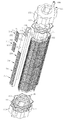
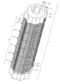
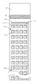
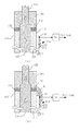
第1の実施形態の光源装置を、図面を参照して説明する。図1は、光源装置の分解斜視図で、図2は図1に示す光源装置の組み立て状態を説明するための外観斜視図、図3は図2に示す光源装置の断面構造を説明するための断面図である。図4は、光源装置の冷却系及びシステム構成を説明するための概略図である。尚、図4では、説明を簡略化するため光源装置を平面的に模式化している。
(First embodiment)
A light source device according to a first embodiment will be described with reference to the drawings. 1 is an exploded perspective view of the light source device, FIG. 2 is an external perspective view for explaining an assembled state of the light source device shown in FIG. 1, and FIG. 3 is a sectional view for explaining the cross-sectional structure of the light source device shown in FIG. It is sectional drawing. FIG. 4 is a schematic diagram for explaining a cooling system and a system configuration of the light source device. In FIG. 4, the light source device is schematically illustrated in a plane in order to simplify the description.

第1の実施形態の光源装置100は、液晶や半導体等の製造プロセス、流体の殺菌や光反応処理、照明等に用いる光源装置であり、主要部として冷却部1を備えている。   The light source device 100 of the first embodiment is a light source device used for manufacturing processes such as liquid crystals and semiconductors, fluid sterilization, photoreaction processing, illumination, and the like, and includes a cooling unit 1 as a main part.

冷却部1は、その外周面に複数の照射部21a、21bを載置するとともに、照射部21a、21bから発生する熱を液冷式で冷却する構成である。   The cooling unit 1 has a configuration in which a plurality of irradiation units 21a and 21b are placed on the outer peripheral surface, and heat generated from the irradiation units 21a and 21b is cooled by a liquid cooling method.

冷却部1は、例えば、図1に示すように、互いに同一形状を成す4つの冷却基体111を環状に配置した集合体の開口した両端を、液漏れを防止する接合部材131、132を介して、それぞれ、蓋部141、151で固定した構造で、外周形状が略八角星形状で、内周形状が8角形をなす柱状体である。   For example, as shown in FIG. 1, the cooling unit 1 is configured such that four ends of an assembly in which four cooling bases 111 having the same shape are arranged in an annular shape are opened via joining members 131 and 132 that prevent liquid leakage. These are columnar bodies having structures fixed by lid portions 141 and 151, each having a substantially octagonal outer peripheral shape and an octagonal inner peripheral shape.

冷却基体111の外装面112と内装面113との間の内部には、長手方向に貫通した冷却水路121〜128が、例えば、押し出し成形または、掘削により形成されている。冷却水路121〜128は、後述する冷却液が循環する経路で、例えば、2つの外装面112毎に設けられている。   Inside the space between the exterior surface 112 and the interior surface 113 of the cooling base 111, cooling water channels 121 to 128 penetrating in the longitudinal direction are formed by, for example, extrusion molding or excavation. The cooling water paths 121 to 128 are paths through which a cooling liquid, which will be described later, circulates. For example, the cooling water paths 121 to 128 are provided for each of the two exterior surfaces 112.

冷却基体111の長手方向の一端側を塞ぐ蓋部141には、図4に示すように、冷却水路121と122、123と124、125と126、及び、127と128を、それぞれ、連結する連結路142、143、144、及び145が設けられている。また、冷却基体111の長手方向の他端側を塞ぐ蓋部151には、冷却水路122と123、124と125、及び、126と127、をそれぞれ連結する連結路152、153及び154と、冷却水路121に接続される取水口155と、冷却水路128に接続される排水口156が設けられている。連結路142〜145、152〜154は、断面形状が例えば、U字状である。   As shown in FIG. 4, the lid 141 that closes one end side in the longitudinal direction of the cooling base 111 is connected to connect the cooling water channels 121 and 122, 123 and 124, 125 and 126, and 127 and 128, respectively. Paths 142, 143, 144, and 145 are provided. Further, the lid 151 that closes the other end side in the longitudinal direction of the cooling base body 111 is connected to cooling passages 122 and 123, 124 and 125, and 126 and 127, respectively. An intake port 155 connected to the water channel 121 and a drain port 156 connected to the cooling water channel 128 are provided. The connection paths 142 to 145 and 152 to 154 have a U-shaped cross section, for example.

これにより、冷却部1内の、取水口155と排水口156との間に、冷却液を流す一連の流路が形成されている。   As a result, a series of flow paths through which the cooling liquid flows are formed between the intake port 155 and the drain port 156 in the cooling unit 1.

冷却基体111、及び、蓋部141、151は、ステンレス、アルミ合金、銅等の導電性の金属で作成される。   The cooling base 111 and the lids 141 and 151 are made of a conductive metal such as stainless steel, aluminum alloy, or copper.

接合部材131、132は、接合面において気密性、水密性を持たせるために用いる固定用シール材である。接合部材131、132は、ガスケットで、ゴム、樹脂等の絶縁体、金属体、または、絶縁体と金属体の複合体等を、接合形状に合わせてシート状に加工した構成である。   The joining members 131 and 132 are fixing sealing materials used for providing airtightness and watertightness on the joining surface. The joining members 131 and 132 are gaskets and have a configuration in which an insulator such as rubber or resin, a metal body, or a composite body of an insulator and a metal body is processed into a sheet shape in accordance with the joining shape.

冷却基体111の集合体の外周部には、例えば、16面の矩形形状の外装面112が備えられており、連続した山折部と谷折部を備えたつづら折り状に形成されている。外装面112には、照射部21aと21bとが載置されている。
ここで、谷折部分の外装面112間の角度αは、例えば、135度で設定され、谷部の一方の外装面112に載置される照射部21a、21bからの出射光が、他方の外装面112に載置される照射部21a、21bに入射して光損失となることを低減するように調整される。このように、複数の外装面112を形成することにより、冷却部1の大型化を招くことなく、複数の照射部21a、21bを効率的に配置することができ、光源装置の大光量化が実現できる。
For example, a 16-sided rectangular exterior surface 112 is provided on the outer peripheral portion of the cooling base 111 assembly, and is formed in a zigzag shape having continuous mountain folds and valley folds. Irradiation parts 21 a and 21 b are placed on the exterior surface 112.
Here, the angle α between the exterior surfaces 112 of the valley fold portion is set at, for example, 135 degrees, and the emitted light from the irradiation units 21a and 21b placed on one exterior surface 112 of the valley portion is the other. Adjustment is made so as to reduce the incidence of light loss on the irradiation parts 21a and 21b placed on the exterior surface 112. In this manner, by forming the plurality of exterior surfaces 112, the plurality of irradiation units 21a and 21b can be efficiently arranged without increasing the size of the cooling unit 1, and the light quantity of the light source device can be increased. realizable.

照射部21a、21bは、例えば、矩形形状の基板211の片面に所定数量の発光ダイオード(LED)212をマトリクス状に配列した構成である。   The irradiation units 21a and 21b have a configuration in which a predetermined number of light emitting diodes (LEDs) 212 are arranged in a matrix on one side of a rectangular substrate 211, for example.

基板211は、窒化アルミやアルミナ等のセラミックス基板等が使用される。   As the substrate 211, a ceramic substrate such as aluminum nitride or alumina is used.

発光ダイオード212は、紫外線、可視光、または赤外線を放射する発光ダイオードで、光源装置100の用途で必要とされる光放射の波長を有する種類が選定される。発光ダイオード212は、例えば、3mm〜4mm角の略矩形形状をなす平面実装型の発光ダイオードで、出射面に設けられたレンズ部材により配光特性が調整される。発光ダイオード212は、例えば、0.5mm〜1mmの間隔で、基板211上に実装される。発光ダイオード212は、基板211に設けられた配線パターン(図示無)により、電気的に接続され、図4に示すように、電源部22から電力を供給することで発光する。   The light-emitting diode 212 is a light-emitting diode that emits ultraviolet light, visible light, or infrared light, and a type having a wavelength of light emission required for the application of the light source device 100 is selected. The light emitting diode 212 is a surface-mounting type light emitting diode having a substantially rectangular shape of 3 mm to 4 mm square, for example, and the light distribution characteristic is adjusted by a lens member provided on the emission surface. For example, the light emitting diodes 212 are mounted on the substrate 211 at intervals of 0.5 mm to 1 mm. The light emitting diode 212 is electrically connected by a wiring pattern (not shown) provided on the substrate 211, and emits light when power is supplied from the power supply unit 22 as shown in FIG.

照射部21a、21bの点灯に際し発生する熱は、図4に示すように、冷却部1内の、冷却水路121〜128、連結路142〜145、152〜154に冷却液を充填し、循環させることで液冷することが出来る。冷却液は、水、油等が使用される。   As shown in FIG. 4, the heat generated when the irradiation units 21 a and 21 b are turned on fills the cooling water channels 121 to 128 and the connection channels 142 to 145 and 152 to 154 in the cooling unit 1 and circulates them. Can be liquid-cooled. As the cooling liquid, water, oil, or the like is used.

例えば、照射部21a、21bからの発熱を受熱した冷却液は、排水口156から排出された後、送液管31を介して、冷液部32に送り込まれ、冷却される。冷液部32は、冷却タンクや熱交換器等から構成される。   For example, the coolant that has received the heat generated from the irradiation units 21 a and 21 b is discharged from the drain port 156, and then sent to the cold liquid unit 32 through the liquid supply pipe 31 to be cooled. The cold liquid part 32 is comprised from a cooling tank, a heat exchanger, etc.

冷却された冷却液は、例えば、送液管33、冷却液を循環させるポンプ34、送液管35、冷却液の供給量を電子的に制御する電磁バルブ36、及び、送液管37を介して、冷却部1の取水口155に供給される。   The cooled coolant is, for example, via a liquid feed pipe 33, a pump 34 for circulating the coolant, a liquid feed pipe 35, an electromagnetic valve 36 for electronically controlling the amount of coolant supplied, and a liquid feed pipe 37. And supplied to the water intake 155 of the cooling unit 1.

冷却液は、再び、冷却部1の冷却水路121〜128、連結路142〜145、152〜154を循環し、照射部21a、21bからの排熱に利用され、この繰り返しによって、照射部21a、21bを冷却する。照射部21a、21bを冷却することにより、発光ダイオード212の温度を低減し、熱による発光効率の低下や部材の熱劣化を抑制することが出来る。   The coolant again circulates in the cooling water channels 121 to 128 and the connection channels 142 to 145 and 152 to 154 of the cooling unit 1 and is used for exhaust heat from the irradiation units 21a and 21b. By repeating this, the irradiation unit 21a, 21b is cooled. By cooling the irradiation parts 21a and 21b, the temperature of the light emitting diode 212 can be reduced, and the decrease in the light emission efficiency and the thermal deterioration of the member due to heat can be suppressed.

ところで、冷却基体111と蓋部141、151は、接合部材131、132を介して気密に接合されるが、製造の不具合や、接合部材131、132等の熱的または経時的な劣化により、気密性が失われ、これらの接合部分から冷却液Wの漏れが発生する可能性がある。   By the way, the cooling base 111 and the lid portions 141 and 151 are airtightly joined through the joining members 131 and 132. However, the airtightness is deteriorated due to a manufacturing defect or deterioration of the joining members 131 and 132 due to thermal or temporal deterioration. There is a possibility that the cooling liquid W may leak from these joints.

これらの接合面からの液漏れを検出するため、冷却部1の冷却基体111の外装面112に対して電気的に絶縁されている位置(第1の位置条件)と、冷却部1からの液漏れ時に外装面112との間に冷却液Wが架橋可能な位置(第2の位置条件)の両方を満足する位置に、検出電極41を配置する。   In order to detect liquid leakage from these joint surfaces, a position (first position condition) that is electrically insulated from the exterior surface 112 of the cooling base 111 of the cooling unit 1 and the liquid from the cooling unit 1 The detection electrode 41 is arranged at a position that satisfies both the position (second position condition) where the coolant W can be bridged between the outer surface 112 and the exterior surface 112 at the time of leakage.

例えば、冷却部1の長手方向を重力方向に沿うように配置する場合は、液漏れした冷却液は、重力により、下側に移動する性質を有する。この場合、例えば、図5に示すように、最上部に配置される照射部21aの基板211の発光ダイオード212を実装する面側(第1の位置条件)で、基板211の上側(第2の位置条件)の位置に直線状の検出電極41を配置することで、上部の蓋部151及び冷却基体111と、接合部材132との接合面からの液漏れを検出することができる。検出電極41は導電性で、銀ペーストや、半田、金メッキパターン等を基板211上に印刷や、蒸着等により形成したものである。   For example, when arrange | positioning so that the longitudinal direction of the cooling part 1 may follow a gravity direction, the cooling fluid which has leaked has the property to move below by gravity. In this case, for example, as shown in FIG. 5, the upper surface of the substrate 211 (second position condition) on the surface side (first position condition) on which the light emitting diode 212 of the substrate 211 of the irradiation unit 21 a disposed at the uppermost part is mounted. By disposing the linear detection electrode 41 at the position (positional condition), it is possible to detect liquid leakage from the bonding surface between the upper lid portion 151 and the cooling base 111 and the bonding member 132. The detection electrode 41 is conductive, and is formed by printing, vapor deposition, or the like on a substrate 211 such as a silver paste, solder, or a gold plating pattern.

検出電極41を用いて、冷却部1からの冷却液Wの液漏れを検出する方法の概略図を図6に示す。液漏れがない場合は、図6(a)に示すように、検出電極41と、冷却基体111の外装面112との間は、絶縁層である空気層及び基板211が介在した状態であり、両者間は電気的に絶縁状態である。ここで、冷却基体111は、例えば、電源部22や外部に設けられた接地端子にハーネスを介して接続され、接地処理Gが施こされている。   A schematic diagram of a method for detecting the leakage of the coolant W from the cooling unit 1 using the detection electrode 41 is shown in FIG. When there is no liquid leakage, as shown in FIG. 6A, an air layer as an insulating layer and the substrate 211 are interposed between the detection electrode 41 and the exterior surface 112 of the cooling base 111, The two are electrically insulated. Here, the cooling base 111 is connected to, for example, a power supply unit 22 or a ground terminal provided outside via a harness, and is subjected to a grounding process G.

一方、冷却液Wの液漏れが発生した際は、例えば、図6(b)に示すように、冷却液Wは、重力または表面張力により、冷却基体111の外装面112に沿って下側に移動し、照射部21aの基板211上に達する。基板211上の検出電極41と、冷却基体111との間に、冷却液Wが架橋する、すなわち、連続的につながるようになると、冷却液Wは導電性で電気を通電するため、検出電極41と冷却基体111との間の電気的特性、例えば、抵抗、静電容量等が変化する。検出電極41と冷却基体111との間の電気的特性の変化を、検出部51で検出することにより、冷却液Wの液漏れの有無を判定できる。検出部51は、例えば、図6に示すように、出力端子Voが設けられており、液漏れが無い場合は低電圧(low)を出力し、液漏れを検出した場合は高電圧(high)で出力する。   On the other hand, when the coolant W leaks, for example, as shown in FIG. 6B, the coolant W is lowered along the exterior surface 112 of the cooling base 111 due to gravity or surface tension. It moves and reaches on the substrate 211 of the irradiation part 21a. When the coolant W crosslinks between the detection electrode 41 on the substrate 211 and the cooling base 111, that is, when the coolant W is continuously connected, the coolant W is electrically conductive and energizes the detection electrode 41. The electrical characteristics between the cooling body 111 and the cooling base 111, for example, resistance, capacitance, etc. change. By detecting a change in electrical characteristics between the detection electrode 41 and the cooling base 111 by the detection unit 51, it is possible to determine whether or not the coolant W has leaked. For example, as shown in FIG. 6, the detection unit 51 is provided with an output terminal Vo, and outputs a low voltage (low) when there is no liquid leakage, and a high voltage (high) when a liquid leakage is detected. To output.

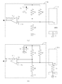
図7に、検出部51の回路構成の一例を示す。検出部51は、比較器(コンパレータ)511を用いて判定を行う。比較器511は、入力電圧Viと基準電圧Vrを入力し、入力電圧Viと基準電圧Vrの大小により、異なる出力電圧Voを出力する構成である。例えば、比較器511は、入力電圧Viが基準電圧Vrに対して大きい場合に、出力電圧Voとして低電圧(low)信号を出力し、逆に、入力電圧Viが基準電圧Vrに対して小さい場合には、出力電圧Voとして高電圧(high)信号を出力する。   FIG. 7 shows an example of the circuit configuration of the detection unit 51. The detection unit 51 performs determination using a comparator (comparator) 511. The comparator 511 is configured to receive the input voltage Vi and the reference voltage Vr and output different output voltages Vo depending on the magnitude of the input voltage Vi and the reference voltage Vr. For example, the comparator 511 outputs a low voltage (low) signal as the output voltage Vo when the input voltage Vi is larger than the reference voltage Vr, and conversely, when the input voltage Vi is smaller than the reference voltage Vr. Outputs a high voltage signal as the output voltage Vo.

電源Vcと、抵抗R1と、抵抗R2とは直列に接続されており、電源Vcと抵抗R2は、接地処理Gされている。ここで、抵抗R2間の電位が、比較器511に基準電圧Vrとして入力される。電源Vcの電位をE、抵抗R1の抵抗値をr1、抵抗R2の抵抗値をr2と置くと、基準電圧VrはVr=r2×E/(r1+r2)で与えられる。   The power source Vc, the resistor R1, and the resistor R2 are connected in series, and the power source Vc and the resistor R2 are grounded. Here, the potential between the resistors R2 is input to the comparator 511 as the reference voltage Vr. When the potential of the power supply Vc is E, the resistance value of the resistor R1 is r1, and the resistance value of the resistor R2 is r2, the reference voltage Vr is given by Vr = r2 × E / (r1 + r2).

一方、検出電極41からの出力は、抵抗R3を介して、電源Vcと直列に接続されている。ここで、電源Vcと冷却基体111は接地処理Gされており、冷却基体111の外装面112に対する検出電極41の電位が、比較器511に入力電圧Viとして入力される。   On the other hand, the output from the detection electrode 41 is connected in series with the power source Vc via the resistor R3. Here, the power source Vc and the cooling base 111 are grounded G, and the potential of the detection electrode 41 with respect to the exterior surface 112 of the cooling base 111 is input to the comparator 511 as the input voltage Vi.

図6(a)に示すように、検出電極41と冷却基体111との間に冷却液Wが存在しない場合は、両者間は絶縁体となるため、入力電圧Viは、電源Vcの電位Eと等しくなり、上述した基準電圧Vrより大きくなり、比較器511の出力Voは、低電圧(low)信号を出力する。   As shown in FIG. 6A, when the coolant W does not exist between the detection electrode 41 and the cooling base 111, an insulator is formed between the two, so that the input voltage Vi is equal to the potential E of the power source Vc. It becomes equal and becomes larger than the above-mentioned reference voltage Vr, and the output Vo of the comparator 511 outputs a low voltage signal.

図6(b)に示すように、検出電極41と冷却基体111との間に冷却液Wが介在すると、冷却液Wが導電性を有するため、両者間で電流が流れる。すなわち、冷却液Wは、等価回路的に抵抗Rwとなる。ここで、冷却液の抵抗Rwの抵抗値をrw、抵抗R3の抵抗値をr3と置くと、入力電圧Viは、Vi=rw×E/(r3+rw)で与えられる。ここで、抵抗r3は、入力電圧Viが、基準電圧Vrより小さくなるように調整されており、これにより、比較器511は、高電圧(high)信号を出力する。比較器511は、冷却液Wの液漏れの有無に応じて、異なる信号を出力することができる。   As shown in FIG. 6B, when the coolant W is interposed between the detection electrode 41 and the cooling base 111, the coolant W has conductivity, so that a current flows between them. That is, the coolant W becomes the resistance Rw in terms of an equivalent circuit. Here, assuming that the resistance value of the coolant resistance Rw is rw and the resistance value of the resistor R3 is r3, the input voltage Vi is given by Vi = rw × E / (r3 + rw). Here, the resistor r3 is adjusted so that the input voltage Vi becomes smaller than the reference voltage Vr, and thereby the comparator 511 outputs a high voltage (high) signal. The comparator 511 can output different signals depending on whether or not the coolant W leaks.

検出部51からの出力信号Voは、例えば、図4に示すように制御部61に導かれる。液漏れ異常を検出した制御部61は、例えば、電源部22を自動停止させて、照射部21a、21bへの電力供給を遮断する。その結果、照射部21a、21bの冷却液Wによる電気的短絡を防止し、照射部21a、21bの破損を事前に防止できる。また、通電された冷却液Wによる漏電も防止でき、作業者の安全性も確保できる。   The output signal Vo from the detection unit 51 is guided to the control unit 61 as shown in FIG. 4, for example. For example, the control unit 61 that has detected the liquid leakage abnormality automatically stops the power supply unit 22 to cut off the power supply to the irradiation units 21a and 21b. As a result, it is possible to prevent an electrical short circuit caused by the coolant W of the irradiation units 21a and 21b, and to prevent the irradiation units 21a and 21b from being damaged in advance. In addition, leakage due to the energized coolant W can be prevented, and operator safety can be ensured.

その他、制御部61に接続された電磁バルブ36を制御して、冷却部1への冷却液の供給を自動停止させ、冷却液の液漏れの拡大を抑制することや、警報装置63を動作させて、作業者に警報音や光の点滅で異常を知らせることも可能である。異常を察知した作業者は、操作パネル62等で、光源装置の停止や、異常からの復旧操作を行うことが可能であり、異常発生時の光源装置の安全性を向上させることが出来る。
(第2の実施形態)
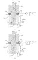
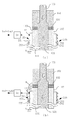
図8及び図9は、光源装置に関する第2の実施形態について説明するためのもので、光源装置の断面図である。この第2の実施形態の各部について、第1の実施形態の光源装置の各部と同一部分は同一符号で示す。
In addition, the electromagnetic valve 36 connected to the control unit 61 is controlled to automatically stop the supply of the cooling liquid to the cooling unit 1 to suppress the expansion of the liquid leakage of the cooling liquid and to operate the alarm device 63. Thus, it is possible to notify the operator of an abnormality by an alarm sound or flashing light. An operator who detects an abnormality can stop the light source device or perform a recovery operation from the abnormality using the operation panel 62 or the like, and can improve the safety of the light source device when an abnormality occurs.
(Second Embodiment)
8 and 9 are cross-sectional views of the light source device for explaining a second embodiment related to the light source device. About each part of this 2nd Embodiment, the same part as each part of the light source device of 1st Embodiment is shown with the same code | symbol.

第2の実施形態では、電源部22は、冷却部1の冷却基体111の内装面113上に設置されている。これにより電源部22も、照射部21bと同様に、冷却液によって効率的に冷却できる。   In the second embodiment, the power supply unit 22 is installed on the interior surface 113 of the cooling base 111 of the cooling unit 1. Thereby, the power supply part 22 can also be efficiently cooled with a cooling liquid similarly to the irradiation part 21b.

照射部21bを設置する外装面112の面積は、電源部22を設置する内装面113の面積より広い構成とすることにより、冷却部1の大型化を招くことなく、複数の照射部21bを効率的に配置することができ、光源装置の大光量化が実現できる。   The area of the exterior surface 112 on which the irradiation unit 21b is installed is configured to be larger than the area of the interior surface 113 on which the power supply unit 22 is installed, so that the plurality of irradiation units 21b can be made efficient without causing an increase in the size of the cooling unit 1. Therefore, it is possible to increase the light quantity of the light source device.

電源部22は、例えば、基板221に回路部品222を実装した構成であるが、回路部品の抵抗やトランジスタ等の発熱部品から発熱する。照射部21bからの発熱量に対して、電源部22からの発熱量は小さいものの、電源部22の回路部品222が温度上昇すると、回路の誤動作や、回路損失の低下、回路寿命の低下を生じる。電源部22を、第1の実施形態と同様な原理で、冷却することで、回路部品222に対する熱の影響を抑制し、安定した回路動作が確保できると共に、回路効率及び回路寿命の向上を図ることができる。   The power supply unit 22 has, for example, a configuration in which the circuit component 222 is mounted on the substrate 221, and generates heat from a heat generating component such as a resistance of the circuit component or a transistor. Although the amount of heat generated from the power supply unit 22 is smaller than the amount of heat generated from the irradiation unit 21b, when the circuit component 222 of the power supply unit 22 rises in temperature, malfunction of the circuit, reduction in circuit loss, and reduction in circuit life occur. . By cooling the power supply unit 22 according to the same principle as in the first embodiment, the influence of heat on the circuit component 222 can be suppressed, stable circuit operation can be ensured, and circuit efficiency and circuit life can be improved. be able to.

電源部22は、例えば、冷却液の向きが異なる2つの冷却水路121と122、123と124、125と126、及び、127と128を跨るようにして、内装面113に配置される。電源部22を、2つの冷却水路を介して、液冷させることで、冷却効率を向上させることができる。   For example, the power supply unit 22 is disposed on the interior surface 113 so as to straddle two cooling water channels 121 and 122, 123 and 124, 125 and 126, and 127 and 128 having different directions of the coolant. Cooling efficiency can be improved by liquid-cooling the power supply part 22 via two cooling water channels.

第2の実施形態では、図9に示すように、冷却部1の長手方向が重力方向に沿うように配置した状態であり、電源部22の基板221の回路部品222が実装される面側(第1の位置条件)で、かつ、重力の上側となる蓋部151側(第2の位置条件)の位置に、冷却液Wの液漏れを検出する検出電極41を形成している。検出電極41と冷却部1の冷却基体111との間の電気的変化を、第1の実施形態と同様に検出部51で検出することで、冷却液Wの液漏れの有無を検出することができる。
(第3の実施形態)
図10は、光源装置に関する第3の実施形態について説明するためのもので、光源装置の断面図である。この第3の実施形態の各部について、第1の実施形態の光源装置の各部と同一部分は同一符号で示す。
In the second embodiment, as shown in FIG. 9, the cooling unit 1 is arranged so that the longitudinal direction thereof is along the direction of gravity, and the surface side on which the circuit component 222 of the substrate 221 of the power supply unit 22 is mounted ( The detection electrode 41 for detecting the leakage of the coolant W is formed at a position on the lid 151 side (second position condition) that is the upper side of gravity under the first position condition). By detecting an electrical change between the detection electrode 41 and the cooling base 111 of the cooling unit 1 by the detection unit 51 as in the first embodiment, it is possible to detect the presence or absence of liquid leakage of the cooling liquid W. it can.
(Third embodiment)
FIG. 10 is a cross-sectional view of a light source device for explaining a third embodiment related to the light source device. About each part of this 3rd Embodiment, the same part as each part of the light source device of 1st Embodiment is shown with the same code | symbol.

第3の実施形態では、冷却部1の冷却基体111と、蓋部151との間に介在する接合部材132内に、冷却部1からの液漏れを検出する検出電極41を配置した構成である。   In 3rd Embodiment, it is the structure which has arrange | positioned the detection electrode 41 which detects the liquid leak from the cooling unit 1 in the joining member 132 interposed between the cooling base | substrate 111 of the cooling unit 1, and the cover part 151. FIG. .

検出電極41は、冷却基体111及び蓋部151との間に、絶縁性の接合部材132を介在させることで、検出電極41と、冷却基体111及び蓋部151との間の絶縁性を確保している。検出電極41の、冷却通路121〜128と対向する側は、空気層に対して露出している。検出電極41と、冷却基体111及び蓋部151との間は、接合部材132及び空気層を介して離間しており、絶縁状態にある(第1の位置条件)。一方、検出電極41の、冷却通路121〜128側は、接合部材132で被覆し、冷却通路121〜128を循環する冷却液を介して、検出電極41と、冷却基体111及びは蓋部151とが、通電しないようにしている。   The detection electrode 41 ensures insulation between the detection electrode 41 and the cooling base 111 and the lid 151 by interposing an insulating bonding member 132 between the cooling base 111 and the lid 151. ing. The side of the detection electrode 41 facing the cooling passages 121 to 128 is exposed to the air layer. The detection electrode 41 is separated from the cooling base 111 and the lid 151 via the bonding member 132 and the air layer, and is in an insulated state (first position condition). On the other hand, the cooling electrode 121 to 128 side of the detection electrode 41 is covered with the joining member 132, and the detection electrode 41, the cooling base 111, and the lid 151 are connected to each other through the cooling liquid circulating through the cooling passages 121 to 128. However, it is not energized.

冷却液Wの液漏れが発生する際は、検出電極41と冷却基体111、または、検出電極41と蓋部151との間に冷却液が架橋する(第2の位置条件)ように、接合部材132の厚みを調整している。   When liquid leakage of the cooling liquid W occurs, the joining member is configured so that the cooling liquid bridges between the detection electrode 41 and the cooling base 111 or between the detection electrode 41 and the lid portion 151 (second position condition). The thickness of 132 is adjusted.

検出電極41は、検出部51に接続される。ここで、検出電極41と出力線との接続を容易にするため、例えば、検出電極41を部分的に大きくして、冷却部1から突出させ、この突出部分(図示無)で端子を接続する構成を採る。   The detection electrode 41 is connected to the detection unit 51. Here, in order to facilitate the connection between the detection electrode 41 and the output line, for example, the detection electrode 41 is partially enlarged and protruded from the cooling unit 1, and a terminal is connected at the protruding portion (not shown). Take the configuration.

検出電極41を用いて、冷却部1からの冷却液Wの液漏れを検出する方法を、図10にて説明する。液漏れがない場合は、図10(a)に示すように、検出電極41と、冷却基体111及び蓋部151との間は、絶縁性の接合部材132及び空気層が介在した状態であり、両者間は電気を導通しない状態である。ここで、冷却基体111または蓋部151は、例えば、接地処理Gが施こされている。   A method of detecting the leakage of the coolant W from the cooling unit 1 using the detection electrode 41 will be described with reference to FIG. When there is no liquid leakage, as shown in FIG. 10A, an insulating bonding member 132 and an air layer are interposed between the detection electrode 41 and the cooling base 111 and the lid 151. There is no electrical conduction between the two. Here, the cooling base 111 or the lid 151 is subjected to a grounding process G, for example.

一方、冷却液Wの液漏れが発生した際は、例えば、図10(b)に示すように、冷却液Wは、冷却基体111、検出電極41、接合部材132、蓋部151の一部表面を覆う。検出電極41と冷却基体111、または、検出電極41と蓋部151との間に、冷却液Wが架橋するようになると、冷却液Wは導電性で電気を通電するため、検出電極41と冷却基体111、または、検出電極41と蓋部151との間の電気的特性、例えば、抵抗、静電容量等が変化する。検出電極41と冷却基体111、または、検出電極41と蓋部151との間の電気的特性の変化を、第1の実施形態と同様に、検出部51で検出することで、冷却液Wの液漏れの有無を検出することができる。   On the other hand, when the leakage of the coolant W occurs, for example, as shown in FIG. 10B, the coolant W is a part of the surface of the cooling base 111, the detection electrode 41, the joining member 132, and the lid 151. Cover. When the coolant W is bridged between the detection electrode 41 and the cooling base 111 or between the detection electrode 41 and the lid 151, the coolant W is electrically conductive and energizes. The electrical characteristics between the substrate 111 or the detection electrode 41 and the lid 151, such as resistance and capacitance, change. As in the first embodiment, the detection unit 51 detects a change in electrical characteristics between the detection electrode 41 and the cooling base 111 or between the detection electrode 41 and the lid 151, so that the coolant W The presence or absence of liquid leakage can be detected.

第1の実施形態および第2の実施形態では、冷却部1の重力の上から下方向に移動する冷却液Wの液漏れを検出できるのに対し、第3の実施形態では、検出電極41を、液漏れが発生する冷却基体111の蓋部141側の接合面に配置することで、重力による冷却液の漏れ方向を考慮しなくても、冷却液Wの液漏れを検出することが可能である。その結果、冷却部1の長手方向を重力方向に沿わせる以外の構成での検出や、冷却基体111の蓋部141側に加えて、蓋部151側での検出も可能となり、液漏れの検出精度を向上できる。   In the first embodiment and the second embodiment, it is possible to detect the leakage of the coolant W that moves downward from above the gravity of the cooling unit 1, whereas in the third embodiment, the detection electrode 41 is provided. The liquid leakage of the cooling liquid W can be detected without considering the leakage direction of the cooling liquid due to gravity by disposing it on the joint surface on the lid 141 side of the cooling base 111 where the liquid leakage occurs. is there. As a result, detection with a configuration other than the longitudinal direction of the cooling unit 1 extending along the direction of gravity and detection on the lid unit 151 side in addition to the lid unit 141 side of the cooling base 111 are possible. Accuracy can be improved.

本発明は上記実施形態に限定されるものではなく、種々の変形が可能である。   The present invention is not limited to the above embodiment, and various modifications are possible.

例えば、照射部21a、21bの光源は、用途に応じた光源であればよいので、発光ダイオード以外に、メタルハライドランプ、低圧水銀ランプ、HIDランプ、または、レーザーダイオード等に置き換えが可能である。電源部22は、夫々の光源に適した構成とすることができる。   For example, since the light sources of the irradiation units 21a and 21b may be any light source according to the application, they can be replaced with a metal halide lamp, a low-pressure mercury lamp, an HID lamp, or a laser diode in addition to the light emitting diode. The power supply unit 22 can have a configuration suitable for each light source.

光源装置の使用形態は、長尺状の冷却部1の長手方向を重力方向に沿う方向で配置した構成を示したが、重力方向に対して傾斜させた構成や、水平方向に配置する構成でも良い。この場合、冷却液は重力の下側に移動すると共に、冷却液の表面張力により、冷却部1の一部表面に沿って広がる性質があるため、液漏れの際に冷却液が広がる範囲を実験的・経験的に求め、その部分に検出電極41を配置する構成でも良い。   Although the usage form of the light source device showed the structure which has arrange | positioned the longitudinal direction of the elongate cooling part 1 in the direction in alignment with a gravitational direction, the structure inclined with respect to the gravitational direction and the structure arrange | positioned in a horizontal direction are also shown. good. In this case, the cooling liquid moves below gravity and spreads along a part of the surface of the cooling unit 1 due to the surface tension of the cooling liquid. A configuration in which the detection electrode 41 is disposed in that portion may be obtained by determination in terms of experience and experience.

冷却部1及び照射部21a、21bは、その周囲を、例えば、石英ガラスを覆い、処理液の内部に浸透させる構成で、使用しても良い。また、この場合、石英ガラスの割れに伴う処理液の漏れを、検出電極41で検出する構成としても良い。   The cooling unit 1 and the irradiation units 21a and 21b may be used with a configuration in which the periphery is covered with, for example, quartz glass and penetrates into the processing liquid. In this case, the detection electrode 41 may be used to detect a leakage of the processing liquid accompanying the cracking of the quartz glass.

また、冷却部1による冷却に伴い、空気中の水分が結露し、照射部21a、21bや、電源部22に付着するため、結露の水分を検出電極41で検出する構成としても良い。   In addition, the moisture in the air condenses with the cooling by the cooling unit 1 and adheres to the irradiation units 21 a and 21 b and the power supply unit 22, so that the moisture of the condensation may be detected by the detection electrode 41.

検出電極41は、照射部21a、21bの一部または電源部22の一部に設けた構成を示したが、例えば、図2に示す重力下側の蓋部141に、検出電極41を設けた独立基板を配置し、冷却基体111の蓋部141側の接合面から下方向に漏れる冷却液を検出する構成でも良い。   The configuration of the detection electrode 41 provided in a part of the irradiation units 21a and 21b or a part of the power supply unit 22 is shown. For example, the detection electrode 41 is provided in the lid 141 on the gravity side shown in FIG. A configuration may be adopted in which an independent substrate is arranged and coolant that leaks downward from the joint surface on the lid 141 side of the cooling base 111 is detected.

検出部51は、比較器を用いた回路構成を示したが、例えばマイコンを用いてもよい。   Although the detection unit 51 has shown the circuit configuration using the comparator, for example, a microcomputer may be used.

本発明のいくつかの実施形態を説明したが、これらの実施形態は、例として提示したものであり、発明の範囲を限定することは意図していない。これら新規な実施形態は、その他の様々な形態で実施されることが可能であり、発明の要旨を逸脱しない範囲で、種々の省略、置き換え、変更を行うことができる。これら実施形態やその変形は、発明の範囲や要旨に含まれるとともに、特許請求の範囲に記載された発明とその均等の範囲に含まれる。   Although several embodiments of the present invention have been described, these embodiments are presented by way of example and are not intended to limit the scope of the invention. These novel embodiments can be implemented in various other forms, and various omissions, replacements, and changes can be made without departing from the scope of the invention. These embodiments and modifications thereof are included in the scope and gist of the invention, and are included in the invention described in the claims and the equivalents thereof.

100 光源装置
1 冷却部
21a、21b 照射部
211 基板
212 発光ダイオード(LED)
22 電源部
41 検出電極
51 検出部
61 制御部
W 冷却液
100 Light source device 1 Cooling unit
21a, 21b Irradiation part 211 Substrate 212 Light emitting diode (LED)
22 Power supply part 41 Detection electrode 51 Detection part 61 Control part W Cooling liquid

Claims (3)

内部に冷却液を流通可能な導電性の冷却部と、
前記冷却液によって冷却可能なように前記冷却部の外部に接続された照射部と、
前記冷却部に対して電気的に絶縁される位置、かつ、前記冷却部からの前記冷却液の液漏れ時に、前記冷却液が前記冷却部との間で架橋可能な位置に設けられた検出電極と、
前記検出電極と前記冷却部との間の電気特性を検出し、その電気特性の変化から前記液漏れを検出する検出部と、
を具備する光源装置。
A conductive cooling section capable of circulating a coolant inside;
An irradiation unit connected to the outside of the cooling unit so as to be cooled by the cooling liquid;
A detection electrode provided at a position that is electrically insulated from the cooling section and at a position where the cooling liquid can be bridged with the cooling section when the cooling liquid leaks from the cooling section. When,
A detection unit that detects an electrical characteristic between the detection electrode and the cooling unit, and detects the liquid leakage from a change in the electrical characteristic;
A light source device comprising:
前記冷却部は長尺な形状であって、その長手方向が重力方向に対して沿うように配置され、前記照射部は前記冷却部の外部に接続された基板と前記基板上に実装された発光ダイオードとで構成され、前記検出電極は前記基板上の上端部に設けられている請求項1に記載の光源装置。   The cooling unit has a long shape, and is arranged such that its longitudinal direction is along the direction of gravity, and the irradiation unit is a substrate connected to the outside of the cooling unit and a light emission mounted on the substrate. The light source device according to claim 1, further comprising a diode, wherein the detection electrode is provided at an upper end portion on the substrate. 前記照射部に電力を供給する電源部と、前記電源部の駆動を制御する制御回路と、を更に備え、前記制御部は前記検出部が前記液漏れを検出したときに前記電源部の駆動を停止させる請求項1または請求項2に記載の光源装置。   A power supply unit that supplies power to the irradiation unit; and a control circuit that controls driving of the power supply unit, wherein the control unit drives the power supply unit when the detection unit detects the liquid leakage. The light source device according to claim 1, wherein the light source device is stopped.
JP2012066778A 2012-03-23 2012-03-23 Light source device Pending JP2013200944A (en)

Priority Applications (1)

Application Number Priority Date Filing Date Title
JP2012066778A JP2013200944A (en) 2012-03-23 2012-03-23 Light source device

Applications Claiming Priority (1)

Application Number Priority Date Filing Date Title
JP2012066778A JP2013200944A (en) 2012-03-23 2012-03-23 Light source device

Publications (1)

Publication Number Publication Date
JP2013200944A true JP2013200944A (en) 2013-10-03

Family

ID=49521062

Family Applications (1)

Application Number Title Priority Date Filing Date
JP2012066778A Pending JP2013200944A (en) 2012-03-23 2012-03-23 Light source device

Country Status (1)

Country Link
JP (1) JP2013200944A (en)

Cited By (8)

* Cited by examiner, † Cited by third party
Publication number Priority date Publication date Assignee Title
JP2015216017A (en) * 2014-05-09 2015-12-03 東芝ライテック株式会社 Lighting device
WO2016171447A1 (en) * 2015-04-21 2016-10-27 주식회사 필룩스 Lighting device and lighting module
KR20160125299A (en) * 2015-04-21 2016-10-31 주식회사 필룩스 Lighting device and lighting module
JP2016194992A (en) * 2015-03-31 2016-11-17 東芝ライテック株式会社 Irradiation lamp and irradiation device
JPWO2016056371A1 (en) * 2014-10-09 2017-04-27 東レ株式会社 Photochemical reaction apparatus, photochemical reaction method using the same, and lactam production method using the same
US10448537B2 (en) 2015-06-11 2019-10-15 Toray Industries, Inc. Power supply device, photochemical reaction device and method in which same is used, and lactam production method
KR20200123915A (en) * 2019-04-23 2020-11-02 (주) 제이엔엠 메카텍 Cooling Device
WO2021149367A1 (en) * 2020-01-24 2021-07-29 ウシオ電機株式会社 Light irradiation device

Cited By (12)

* Cited by examiner, † Cited by third party
Publication number Priority date Publication date Assignee Title
JP2015216017A (en) * 2014-05-09 2015-12-03 東芝ライテック株式会社 Lighting device
JPWO2016056371A1 (en) * 2014-10-09 2017-04-27 東レ株式会社 Photochemical reaction apparatus, photochemical reaction method using the same, and lactam production method using the same
US10414724B2 (en) 2014-10-09 2019-09-17 Toray Industries, Inc. Photochemical reaction device, photochemical reaction method using same, and lactam production method using said method
JP2016194992A (en) * 2015-03-31 2016-11-17 東芝ライテック株式会社 Irradiation lamp and irradiation device
WO2016171447A1 (en) * 2015-04-21 2016-10-27 주식회사 필룩스 Lighting device and lighting module
KR20160125299A (en) * 2015-04-21 2016-10-31 주식회사 필룩스 Lighting device and lighting module
KR101882938B1 (en) 2015-04-21 2018-07-27 주식회사 필룩스 Lighting device and lighting module
US10448537B2 (en) 2015-06-11 2019-10-15 Toray Industries, Inc. Power supply device, photochemical reaction device and method in which same is used, and lactam production method
KR20200123915A (en) * 2019-04-23 2020-11-02 (주) 제이엔엠 메카텍 Cooling Device
KR102247484B1 (en) * 2019-04-23 2021-05-03 (주) 제이엔엠 메카텍 Evaporator for Cooling Device for Cooling Semiconductor elements and Cooling Device Including the Same
WO2021149367A1 (en) * 2020-01-24 2021-07-29 ウシオ電機株式会社 Light irradiation device
JP7331713B2 (en) 2020-01-24 2023-08-23 ウシオ電機株式会社 Light irradiation device

Similar Documents

Publication Publication Date Title
JP2013200944A (en) Light source device
RU2475675C2 (en) Lighting device and method of cooling lighting device
KR101819024B1 (en) Thermal trim for a luminaire
JP6140672B2 (en) Insulated LED device
US20100253226A1 (en) Energy-saving lighting fixture
TWI445897B (en) Semiconductor light module
RU2559808C2 (en) Lighting fixture (versions)
US20100177519A1 (en) Electro-hydrodynamic gas flow led cooling system
JP2010182796A (en) Led lamp
JP5725278B2 (en) Light source device
US20130063946A1 (en) Lighting apparatus
JP2012243393A (en) Lighting fixture
JP2008235118A (en) Lighting system and method of manufacturing same
FI116116B (en) hybrid fittings
US8917011B2 (en) LED heat dissipation structure
US10480770B2 (en) Lamp
US8936378B2 (en) LED light source
US9523494B2 (en) LED lighting unit
KR101262661B1 (en) Airfield light module for waterproof
JP6192586B2 (en) Lighting device
JP2009194008A (en) Light-emitting diode module, lighting system, and wiring pattern setting method of light-emitting diode module
JP6544002B2 (en) Irradiator
EP2834559B1 (en) Led light structure
JP2012089417A (en) Light source device
KR101105006B1 (en) LED heat emission assembly and method of manufacturing the same