JP2013200505A - Pressure member for fixing, fixing device, and image forming apparatus - Google Patents
Pressure member for fixing, fixing device, and image forming apparatus Download PDFInfo
- Publication number
- JP2013200505A JP2013200505A JP2012069962A JP2012069962A JP2013200505A JP 2013200505 A JP2013200505 A JP 2013200505A JP 2012069962 A JP2012069962 A JP 2012069962A JP 2012069962 A JP2012069962 A JP 2012069962A JP 2013200505 A JP2013200505 A JP 2013200505A
- Authority
- JP
- Japan
- Prior art keywords
- layer
- fixing
- pressure member
- adhesive
- roll
- Prior art date
- Legal status (The legal status is an assumption and is not a legal conclusion. Google has not performed a legal analysis and makes no representation as to the accuracy of the status listed.)
- Pending
Links
Images


Classifications
-
- G—PHYSICS
- G03—PHOTOGRAPHY; CINEMATOGRAPHY; ANALOGOUS TECHNIQUES USING WAVES OTHER THAN OPTICAL WAVES; ELECTROGRAPHY; HOLOGRAPHY
- G03G—ELECTROGRAPHY; ELECTROPHOTOGRAPHY; MAGNETOGRAPHY
- G03G15/00—Apparatus for electrographic processes using a charge pattern
- G03G15/20—Apparatus for electrographic processes using a charge pattern for fixing, e.g. by using heat
- G03G15/2003—Apparatus for electrographic processes using a charge pattern for fixing, e.g. by using heat using heat
- G03G15/2014—Apparatus for electrographic processes using a charge pattern for fixing, e.g. by using heat using heat using contact heat
- G03G15/2053—Structural details of heat elements, e.g. structure of roller or belt, eddy current, induction heating
-
- G—PHYSICS
- G03—PHOTOGRAPHY; CINEMATOGRAPHY; ANALOGOUS TECHNIQUES USING WAVES OTHER THAN OPTICAL WAVES; ELECTROGRAPHY; HOLOGRAPHY
- G03G—ELECTROGRAPHY; ELECTROPHOTOGRAPHY; MAGNETOGRAPHY
- G03G15/00—Apparatus for electrographic processes using a charge pattern
- G03G15/20—Apparatus for electrographic processes using a charge pattern for fixing, e.g. by using heat
- G03G15/2003—Apparatus for electrographic processes using a charge pattern for fixing, e.g. by using heat using heat
- G03G15/2014—Apparatus for electrographic processes using a charge pattern for fixing, e.g. by using heat using heat using contact heat
- G03G15/206—Structural details or chemical composition of the pressure elements and layers thereof
-
- G—PHYSICS
- G03—PHOTOGRAPHY; CINEMATOGRAPHY; ANALOGOUS TECHNIQUES USING WAVES OTHER THAN OPTICAL WAVES; ELECTROGRAPHY; HOLOGRAPHY
- G03G—ELECTROGRAPHY; ELECTROPHOTOGRAPHY; MAGNETOGRAPHY
- G03G2215/00—Apparatus for electrophotographic processes
- G03G2215/20—Details of the fixing device or porcess
- G03G2215/2003—Structural features of the fixing device
- G03G2215/2016—Heating belt
- G03G2215/2035—Heating belt the fixing nip having a stationary belt support member opposing a pressure member
Abstract
Description
本発明は、定着用加圧部材、定着装置、および画像形成装置に関する。 The present invention relates to a fixing pressure member, a fixing device, and an image forming apparatus.
電子写真方式の画像形成装置におけるトナー像の定着方法として、熱源で加熱された加熱部材と、内部に気泡が存在するゴム等の材料を用いた弾性層を外周面に形成した加圧部材と、を用いた定着方法がある。こうした定着方法では、循環駆動される加熱部材に加圧部材を押し当てて加圧部材の弾性層を押しつぶすことで、加圧部材の周方向にある幅を持つ接触領域を形成し、この接触領域にトナー像を形成した記録媒体を進入させ、トナー像が溶融、加圧されて、記録媒体に定着される。 As a fixing method of a toner image in an electrophotographic image forming apparatus, a heating member heated by a heat source, a pressure member formed on an outer peripheral surface with an elastic layer using a material such as rubber in which bubbles are present, and There is a fixing method using. In such a fixing method, a contact region having a width in the circumferential direction of the pressure member is formed by pressing the pressure member against the circulatingly driven heating member and crushing the elastic layer of the pressure member. The recording medium on which the toner image is formed is entered, and the toner image is melted and pressurized to be fixed on the recording medium.
上記態様の定着方法に用いる加圧部材として、例えば、特許文献1には、弾性層の上にプライマーおよび樹脂材を順次塗布し、焼成することにより弾性層の上にプライマー層および該樹脂材からなる樹脂層が形成される弾性回転体であって前記弾性層とプライマー層との境界をなす前記弾性層の表面には多数の空孔が空孔率3から50%にて形成され、該空孔にプライマー層の樹脂材が進入し係止されている弾性回転体が開示されている。 As a pressure member used in the fixing method of the above aspect, for example, in Patent Document 1, a primer and a resin material are sequentially applied on an elastic layer and baked to form the primer layer and the resin material on the elastic layer. A large number of pores are formed at a porosity of 3 to 50% on the surface of the elastic layer forming the boundary between the elastic layer and the primer layer. An elastic rotating body is disclosed in which a resin material of a primer layer enters and is locked in a hole.
また、特許文献2には、芯金と、この芯金の外周にこれを取り巻くように配設されたスポンジ層と、このスポンジ層の外周に、接着剤層を介して接着された薄肉スリーブと、この薄肉スリーブの外周にこれを覆うように配設された離型層とを具備する方法が開示されている。 Patent Document 2 discloses a cored bar, a sponge layer disposed around the outer periphery of the cored bar, and a thin sleeve bonded to the outer periphery of the sponge layer via an adhesive layer. And a release layer disposed on the outer periphery of the thin sleeve so as to cover it.
また、特許文献3には、芯金と、この芯金の外周にこれを取り巻くように配設されたスポンジ層と、このスポンジ層の外周に、接着剤層を介して接着された薄肉スリーブと、この薄肉スリーブの外周にこれを覆うように配設された離型層とを具備し、スポンジ層の外径と薄肉スリーブの内径とを同一に設定する方法が開示されている。 Further, Patent Document 3 discloses a cored bar, a sponge layer disposed around the outer periphery of the cored bar, and a thin sleeve bonded to the outer periphery of the sponge layer via an adhesive layer. Further, a method is disclosed in which a release layer is provided on the outer periphery of the thin sleeve so as to cover it, and the outer diameter of the sponge layer and the inner diameter of the thin sleeve are set to be the same.
また、特許文献4には、金属その他の軸芯部材と、上記軸芯部材の周囲に形成されたシリコンゴムの多孔性弾性層と、上記多孔性弾性層の外周面に皮膜状に形成された金属その他の外形表面層とを有するロール体において、上記ロール体は、円柱または円筒形状に形成された軸芯部材と、シリコンゴム素材に発泡剤を混入して円筒形状に加硫成形した素地ロール体と、金属その他の耐熱性素材で円筒形状に形成された表面スリーブ体と、から構成し、上記素地ロール体は表面に形成された成型時の表皮層を研磨若しくは剥離する表皮除去加工を施し、この表皮層を除去した凹凸表面を有する素地ロール体を上記表面スリーブ体に接着剤を用いることなく圧入することによって固着する方法が開示されている。 Patent Document 4 discloses a metal or other shaft core member, a porous elastic layer of silicon rubber formed around the shaft core member, and a film formed on the outer peripheral surface of the porous elastic layer. In a roll body having a metal or other outer surface layer, the roll body includes a shaft core member formed in a columnar shape or a cylindrical shape, and a base roll vulcanized and formed into a cylindrical shape by mixing a foaming agent in a silicon rubber material. A body and a surface sleeve body formed of a metal or other heat-resistant material in a cylindrical shape, and the base roll body is subjected to a skin removal process for polishing or peeling the skin layer formed on the surface at the time of molding. A method is disclosed in which a base roll body having an uneven surface from which the skin layer has been removed is fixed by press-fitting the surface sleeve body without using an adhesive.
また、特許文献5には、基材外周に、有機マイクロバルーンおよび連泡化剤を含有するゴム材料からなるゴム層、および、離型性樹脂チューブからなる離型性樹脂層を順に有する定着部材であって、ゴム層が、離型性樹脂チューブを被覆した状態でゴム材料を硬化させることにより形成されたものである定着部材において、離型性樹脂チューブの内面に7から40μm厚さのプライマ層を設ける方法が開示されている。 Patent Document 5 discloses a fixing member having a rubber layer made of a rubber material containing an organic microballoon and a foaming agent and a releasable resin layer made of a releasable resin tube in order on the outer periphery of the substrate. In the fixing member in which the rubber layer is formed by curing the rubber material in a state where the release resin tube is covered, a primer having a thickness of 7 to 40 μm is formed on the inner surface of the release resin tube. A method of providing a layer is disclosed.
本発明の課題は、トナー像を定着する際のトナーの溶融ムラの発生が抑制される定着用加圧部材を提供することにある。 An object of the present invention is to provide a fixing pressure member that suppresses the occurrence of uneven melting of toner when fixing a toner image.
上記課題は以下の本発明によって解決される。即ち、
請求項1に係る発明は、
円筒状の基材と、
前記基材の外周面上に、気泡が内在し弾性を有する第1の層と、
前記第1の層の外周面上に、第2の層と、
前記第1の層および前記第2の層を接着する接着剤層と、
前記第1の層および前記第2の層で挟まれる領域に、少なくとも軸方向の一端にまで接着剤が存在しない未接着領域と、
を有する定着用加圧部材である。
The above problems are solved by the present invention described below. That is,
The invention according to claim 1
A cylindrical substrate;
On the outer peripheral surface of the substrate, a first layer having bubbles and having elasticity,
On the outer peripheral surface of the first layer, a second layer;
An adhesive layer for bonding the first layer and the second layer;
An unbonded region where no adhesive is present at least at one end in the axial direction in a region sandwiched between the first layer and the second layer;
A fixing pressure member.
請求項2に係る発明は、
前記接着剤層は、前記第1の層の外周表面において軸方向の全領域にわたって周方向の少なくとも一部を覆うよう形成されている請求項1に記載の定着用加圧部材である。
The invention according to claim 2
2. The fixing pressure member according to claim 1, wherein the adhesive layer is formed so as to cover at least a part of the circumferential direction over the entire region in the axial direction on the outer circumferential surface of the first layer.
請求項3に係る発明は、
前記第1の層は、前記気泡および前記未接着領域と繋がる切れ込みを有する請求項1または請求項2に記載の定着用加圧部材である。
The invention according to claim 3
3. The fixing pressure member according to claim 1, wherein the first layer has a cut connected to the bubble and the non-bonded region.
請求項4に係る発明は、
前記未接着領域が、軸方向の一端から他端にまで繋がる請求項1〜請求項3の何れか1項に記載の定着用加圧部材である。
The invention according to claim 4
The pressure member for fixing according to any one of claims 1 to 3, wherein the unbonded region is connected from one end to the other end in the axial direction.
請求項5に係る発明は、
請求項1に記載の定着用加圧部材と、
加熱装置と、
前記加熱装置により加熱され、前記定着用加圧部材を押し当てられて該定着用加圧部材との間に接触領域を形成し、該接触領域にトナー像が表面に形成された記録媒体を挟んで周回移動し前記トナー像を加熱および加圧して定着する加熱定着部材と、
を有する定着装置である。
The invention according to claim 5
A fixing pressure member according to claim 1;
A heating device;
Heated by the heating device and pressed against the fixing pressure member to form a contact area with the fixing pressure member, and a recording medium having a toner image formed on the surface is sandwiched between the contact areas. A heating fixing member that moves around and heats and pressurizes and fixes the toner image;
A fixing device having
請求項6に係る発明は、
トナー像を形成し、記録媒体上に該トナー像を転写するトナー像形成部と、
請求項5に記載の定着装置と、
前記トナー像の形成された前記記録媒体を前記加熱部材と前記定着用加圧部材との接触領域に搬送する搬送装置と、
を有する画像形成装置である。
The invention according to claim 6
A toner image forming unit that forms a toner image and transfers the toner image onto a recording medium;
A fixing device according to claim 5;
A conveying device that conveys the recording medium on which the toner image is formed to a contact area between the heating member and the fixing pressure member;
An image forming apparatus having
請求項1に係る発明によれば、気泡が内在し弾性を有する第1の層と第2の層とを接着する接着剤層を有し且つ前記第1の層および前記第2の層で挟まれる領域に少なくとも軸方向の一端にまで接着剤が存在しない未接着領域を有するとの要件を満たさない場合に比べ、トナー像を定着する際のトナーの溶融ムラの発生が抑制される定着用加圧部材が提供される。 According to the first aspect of the present invention, there is provided an adhesive layer for adhering the first layer and the second layer having air bubbles and having elasticity, and is sandwiched between the first layer and the second layer. Compared to the case where the requirement of having an unadhered area where no adhesive exists at least at one end in the axial direction is not satisfied in the area to be fixed, the addition of the fixing for suppressing the occurrence of toner non-uniformity in fixing the toner image is suppressed. A pressure member is provided.
請求項2に係る発明によれば、接着剤層が第1の層の外周表面において軸方向の全領域にわたって周方向の少なくとも一部を覆うよう形成されていない場合に比べ、第1の層と第2の層との剥離が抑制された定着用加圧部材が提供される。 According to the invention which concerns on Claim 2, compared with the case where the adhesive bond layer is not formed so that at least one part of the circumferential direction may be covered over the whole area | region of an axial direction in the outer peripheral surface of a 1st layer, A fixing pressure member in which separation from the second layer is suppressed is provided.
請求項3に係る発明によれば、第1の層が気泡および未接着領域と繋がる切れ込みを有しない場合に比べ、トナー像を定着する際のトナーの溶融ムラの発生が抑制される定着用加圧部材が提供される。 According to the third aspect of the invention, compared to the case where the first layer does not have a notch that is connected to the bubble and the non-bonded area, the fixing application that suppresses the occurrence of uneven melting of the toner when fixing the toner image is suppressed. A pressure member is provided.
請求項4に係る発明によれば、未接着領域が軸方向の一端から他端にまで繋がっていない場合に比べ、トナー像を定着する際のトナーの溶融ムラの発生が抑制される定着用加圧部材が提供される。 According to the fourth aspect of the present invention, compared to the case where the non-bonded region is not connected from one end to the other end in the axial direction, the addition of the fixing for suppressing the occurrence of uneven melting of the toner when fixing the toner image. A pressure member is provided.
請求項5に係る発明によれば、気泡が内在し弾性を有する第1の層と第2の層とを接着する接着剤層を有し且つ前記第1の層および前記第2の層で挟まれる領域に少なくとも軸方向の一端にまで接着剤が存在しない未接着領域を有する定着用加圧部材を備えない場合に比べ、光沢ムラの発生が抑制された画像が得られる定着装置が提供される。 According to the invention which concerns on Claim 5, it has an adhesive layer which adhere | attaches the 1st layer and 2nd layer which have a bubble and has elasticity, and is pinched | interposed by the said 1st layer and the said 2nd layer There is provided a fixing device capable of obtaining an image in which occurrence of gloss unevenness is suppressed as compared with a case where a fixing pressure member having an unbonded region in which no adhesive is present at least at one end in the axial direction is not provided in the region to be formed. .
請求項6に係る発明によれば、気泡が内在し弾性を有する第1の層と第2の層とを接着する接着剤層を有し且つ前記第1の層および前記第2の層で挟まれる領域に少なくとも軸方向の一端にまで接着剤が存在しない未接着領域を有する定着用加圧部材を備えない場合に比べ、光沢ムラの発生が抑制された画像が得られる画像形成装置が提供される。 According to the sixth aspect of the present invention, the adhesive layer for adhering the first layer and the second layer having air bubbles and having elasticity is sandwiched between the first layer and the second layer. An image forming apparatus is provided that can provide an image in which occurrence of gloss unevenness is suppressed as compared with a case where a fixing pressure member having an unbonded region in which no adhesive is present at least in one end in the axial direction is provided in the region to be formed. The
以下、図面を参照して本発明の実施形態について説明する。 Hereinafter, embodiments of the present invention will be described with reference to the drawings.
[画像形成装置]
図1は、本実施形態の一実施態様にかかる画像形成装置を示す概略構成図である。
[Image forming apparatus]
FIG. 1 is a schematic configuration diagram illustrating an image forming apparatus according to an embodiment of the present embodiment.
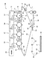
図1に示す画像形成装置100は、中間転写方式のプリンタである。画像形成装置100は、電子写真方式により各色成分のトナー像を形成する複数の画像形成ユニット1Y,1M,1C,1Kと、各画像形成ユニット1Y,1M,1C,1Kにより形成された各色成分トナー像を中間転写ベルト15に順次転写(1次転写)させる1次転写部10と、中間転写ベルト15上に転写された重畳トナー画像を記録媒体である用紙Pに一括転写(2次転写)させる2次転写部20と、2次転写された画像を用紙P上に定着させる定着装置60と、を備えている。画像形成装置100には、各装置各部の動作を制御する制御部40も備えられている。ここで、画像形成ユニット1Y,1M,1C,1K、中間転写ベルト15、1次転写部10、および2次転写部20の組合せが、本実施形態にいうトナー像形成部の一例に相当する。
An
画像形成装置100は、いわゆるタンデム型のプリンタであり、画像形成ユニット1Y,1M,1C,1Kは、中間転写ベルト15の上流側から、イエロー(Y)、マゼンタ(M)、シアン(C)、黒(K)が並列的に配置されている。画像形成ユニット1Y,1M,1C,1Kは、使用するトナーの色が異なる以外は互いに等しい構成を有している。
イエローを担当する画像形成ユニット1Yに代表させて符号を付して説明すると、画像形成ユニット1Yは、矢印A方向に回転する感光体ドラム11と、感光体ドラム11を帯電する帯電器12と、感光体ドラム11上に露光ビームBmを照射して静電潜像を書き込むレーザ露光器13と、イエローのトナーが収容されて感光体ドラム11上の静電潜像をトナーにより現像する現像器14と、感光体ドラム11上に形成された各色成分トナー像を中間転写ベルトに転写する1次転写部10と、感光体ドラム11上の残留トナーを除去するドラムクリーナ17と、を有する。
The
The
中間転写ベルト15は、例えば、樹脂に帯電防止剤を含有させた材料であるフィルム状の無端のベルトである。中間転写ベルト15は、複数のロールに架け渡されており、図1に示すB方向に周回移動している。中間転写ベルト15が架け渡されるロールは、中間転写ベルトを駆動する駆動ロール31と、中間転写ベルト15が感光体ドラムの配列に沿って延びた領域の両端を支持する支持ロール32と、中間転写ベルト15に対して一定の張力を与える張力ロール33と、2次転写部に設けられる背面ロール25と、クリーニング部に設けられたクリーニング部背面ロール34である。駆動ロールは、モータ(図示せず)により駆動されて、中間転写ベルト15を予め定められた速度で周回移動させる。張力ロールは、中間転写ベルトの蛇行を防止する補正ロールとしても機能する。
The
1次転写部は、中間転写ベルト15を挟んで感光体ドラム11に対向して配置された1次転写ロール16を有する。1次転写ロール16は、感光体ドラム11との間に中間転写ベルト15を挟み付けている。1次転写ロール16には、トナーの帯電極性(本例では、マイナス極性。以下同じ。)とは逆極性の電圧(1次転写バイアス)が印加される。
The primary transfer unit includes a
2次転写部は、中間転写ベルト15のトナー像保持面側に配置される2次転写ロール22と、背面ロール25と、背面ロール25に2次転写バイアスを印加する給電ロール26とを備えている。背面ロール25は、中間転写ベルト15の内周面側、すなわち、中間転写ベルト15を挟んで2次転写ロール22の反対側に配置されており、2次転写ロール22の対向電極をなしている。また、黒の画像形成ユニット1Kよりも下流側には、画質調整を行うための画像濃度センサ43が配設されている。
The secondary transfer unit includes a
また、中間転写ベルト15の2次転写部20よりも下流側には、2次転写後の中間転写ベルト15上の残留トナーや紙粉を除去することで、中間転写ベルト表面をクリーニングする中間転写ベルトクリーナ35が設けられている。一方、イエローの画像形成ユニット1Yよりも上流側には、各画像形成ユニット1Y,1M,1C,1Kにおける画像形成タイミングをとるための基準信号を発生する基準センサ(ホームポジションセンサ)42が配設されている。
Further, on the downstream side of the
さらに、画像形成装置100は、用紙搬送系として、用紙Pを収容する用紙収容部50と、この用紙収容部50に集積された用紙Pを繰り出す取り出しロール51と、用紙Pを搬送する搬送ロール52と、搬送ロール52により搬送された用紙Pを2次転写部へと案内する案内部材53と、2次転写ロール22により2次転写された後の用紙Pを定着装置60へと搬送する搬送ベルト55と、用紙Pを定着装置60に導く定着入口ガイド56と、を備えている。ここで、搬送ベルト55、および定着入口ガイド56の組合せが、本実施形態にいう搬送装置の一例に相当する。
Further, the
定着装置60は、図2に示すごとく、加圧ロール111と加熱定着ベルト110とを有している。加圧ロール111は図示しない駆動装置により回転され、加熱定着ベルト110は、加圧ロール111に従動して周回移動する。加圧ロール111および加熱定着ベルト110は、用紙Pを間に挟んで加熱および加圧することによって、未定着トナー像を用紙P上に定着する。定着装置60のより詳細な構成については、後に説明する。
As shown in FIG. 2, the fixing
次に、画像形成装置100の基本的なプロセスについて説明する。
Next, a basic process of the
画像形成装置100は、図示しない画像読取装置やパーソナルコンピュータ(PC)から出力された画像データに画像処理を施した後、画像データをY、M、C、Kの4色の色材階調データに変換し、画像形成ユニット1Y,1M,1C,1Kのレーザ露光器13に供給する。レーザ露光器13は、供給された色材階調データに応じて、例えば、半導体レーザから出射された露光ビームBmを画像形成ユニット1Y,1M,1C,1Kの各々の感光体ドラム11に照射する。画像形成ユニット1Y,1M,1C,1Kの各感光体ドラム11は、帯電器12によって表面が帯電された後、このレーザ露光器13によって表面が走査露光され、静電潜像が形成される。形成された静電潜像は、各々の画像形成ユニット1Y,1M,1C,1Kの現像器14によって、Y、M、C、Kの各色のトナー像として現像される。
The
画像形成ユニット1Y,1M,1C,1Kの感光体ドラム11上に形成されたトナー像は、1次転写部10において、中間転写ベルト15上の表面に順次重ね合わせて転写される。トナー像は、中間転写ベルト15の表面に順次転写された後、中間転写ベルト15の移動に伴って2次転写部に搬送される。この一方で、用紙搬送系では、トナー像が2次転写部20に搬送されるタイミングに合わせて取り出しロール51が用紙収容部に収容された用紙Pを繰り出す。取り出しロール51によって繰り出された用紙Pは、搬送ロール52により搬送され、トナー像が保持された中間転写ベルト15の移動タイミングに合わせて2次転写部20に到達する。
The toner images formed on the
2次転写部20は、中間転写ベルト15上に保持されたトナー像を、中間転写ベルト15と2次転写ロール22との間に挟み込まれた用紙P上に転写する。トナー像が静電転写された用紙Pは、搬送ベルト55によって定着装置60まで搬送される。定着装置60は、用紙P上のトナー像に熱および圧力を加え、用紙P上にトナー像を定着する。定着画像が形成された用紙Pは排紙部(図示しない)に排出される。
The
一方、2次転写部20で中間転写ベルト15から用紙Pに転写しきれず中間転写ベルト15上に残った残留トナーは、中間転写ベルトクリーナ35によって中間転写ベルト15上から除去される。
On the other hand, residual toner remaining on the
[定着装置]
ここで、図1に示す画像形成装置を構成する定着装置について説明する。定着装置は、本実施形態の定着装置の一実施形態である。
[Fixing device]
Here, the fixing device constituting the image forming apparatus shown in FIG. 1 will be described. The fixing device is an embodiment of the fixing device of the present embodiment.
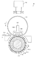
図2は、図1に示す定着装置の構成を示す断面図である。
定着装置60は、電磁誘導加熱方式の定着装置である。定着装置60は、筐体の内部に加熱定着ベルト110、圧力パッド113Bおよびホルダ113Aを有する圧力部材113、加圧ロール111、磁場発生装置112を設けて構成される。
FIG. 2 is a cross-sectional view showing the configuration of the fixing device shown in FIG.
The fixing
ここで、加圧ロール111が本実施形態にいう加圧部材の一例に相当し、加熱定着ベルト110が本実施形態にいう加熱定着部材の一例に相当し、磁場発生装置112が本実施形態にいう加熱装置の一例に相当する。
Here, the
図2に示すように、圧力部材113の下面と加圧ロール111の外周面との間には加熱定着ベルト110が挟まれている。加圧ロール111の芯金111Aの両端は軸受によって支持されており、加圧ロール111は自在に回転し得るようになっている。軸受には、バネによって上向きの力が働いており、この力によって加圧ロール111の外周面は加熱定着ベルト110を介して圧力部材113の下面に押し当てられている。加圧ロール111の弾性層111Bおよび離型層111Dは弾性変形し得るものであるため、図2に示すごとく、加熱定着ベルト110と加圧ロール111との間には、加圧ロール111の周方向にある幅を持つ接触領域が形成される。
As shown in FIG. 2, the
加圧ロール111は、駆動手段により図2において矢印Bの方向に回転される。加圧ロール111が回転すると、加熱定着ベルト110の外周面に対して摩擦力が作用し、加熱定着ベルト110の内周面が圧力部材113の下面を擦りながら矢印Cの方向に駆動される。
この場合、圧力部材113の下面と加熱定着ベルト110の内周面との間に生じる摩擦力を低減させるため、圧力部材113の下面と加熱定着ベルト110の内周面との間に耐熱性グリスなどの潤滑剤を介在させるのが望ましい。
The
In this case, in order to reduce the frictional force generated between the lower surface of the
磁場発生装置112は、後述する加熱定着ベルト110の発熱層を発熱させるための交番磁束を発生する。磁場発生装置112は、励磁回路、磁性コア、励磁コイルおよび励磁コイル保持部材により構成される。
磁性コアは、フェライトやパーマロイ等、透磁率の高い素材で形成される。励磁回路は、20kHzから500kHzの交番電流を発生する。励磁コイルは、励磁回路から供給される交番電流によって交番磁束を発生する。励磁コイルは、例えば一本ずつが絶縁性の物質で被覆された銅線を複数本束ねた束線を複数回巻いて形成されている。
磁性コアおよび励磁コイルは、円筒状に保持された加熱定着ベルトの外周面に沿うように形成されている。本実施形態では、加熱定着ベルトの外面と励磁コイルとの間の距離が2mmになるよう設定している。
The
The magnetic core is formed of a material having high magnetic permeability such as ferrite or permalloy. The excitation circuit generates an alternating current of 20 kHz to 500 kHz. The exciting coil generates an alternating magnetic flux by the alternating current supplied from the exciting circuit. The exciting coil is formed, for example, by winding a bundle of a plurality of copper wires each coated with an insulating material a plurality of times.
The magnetic core and the exciting coil are formed along the outer peripheral surface of the heat fixing belt held in a cylindrical shape. In the present embodiment, the distance between the outer surface of the heat fixing belt and the exciting coil is set to 2 mm.
圧力部材113は、ホルダ113Aにシリコーンゴム等からなる圧力パッド113Bを装着したものである。本実施形態では、シリコーンゴムの硬度を20°(JIS−A)とした。ホルダ113Aは、ステンレス鋼等の金属や耐熱性の高い合成樹脂等からなる。
The
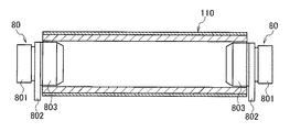
ここで図3に、図2における加熱定着ベルトを用紙が搬送される方向から見た断面図を示す。図3に示すごとく、加熱定着ベルト110の両端部には端部規制部材80が設けられている。端部規制部材80は、円筒部803、フランジ802、保持部801から構成されている。円筒部803は、加熱定着ベルト110を円筒状に保持した場合の内径よりも小さな外径を有している。フランジ802は、円筒部803に保持された加熱定着ベルト110の外径よりも大きな外径を有している。加熱定着ベルト110の両端部はフランジ802に突き当てられて、これによって加熱定着ベルト110の蛇行が防止される。フランジ802の外側には保持部801が設けられており、保持部801は筐体に固定されている。
Here, FIG. 3 shows a cross-sectional view of the heat-fixing belt in FIG. As shown in FIG. 3,
加熱定着ベルト110は環状のベルトであり、内面側から順に基材層、発熱層、弾性層、離型層を積層した層状構造をなしている。
The
基材層は、例えば厚さ10μm以上100μm以下の耐熱性の高い樹脂で形成されている。樹脂としては、例えばポリエステル、ポリエチレンテレフタレート、ポリエーテルサルフォン、ポリエーテルケトン、ポリサルフォン、ポリイミド、ポリイミドアミド、ポリアミド等が挙げられる。本実施形態では、厚さ50μmのポリイミドを用いている。 The base material layer is formed of a resin having high heat resistance with a thickness of 10 μm to 100 μm, for example. Examples of the resin include polyester, polyethylene terephthalate, polyether sulfone, polyether ketone, polysulfone, polyimide, polyimide amide, and polyamide. In the present embodiment, polyimide having a thickness of 50 μm is used.
発熱層は、鉄・コバルト・ニッケル・銅・クロム等の金属層を、例えば1μm以上50μm以下の厚みで形成したものが用いられる。加熱定着ベルト110が圧力部材113の形状に沿って変形するよう、発熱層の厚さはより薄くすることが望ましい。本実施形態では、発熱層として、導電率の高い銅を、発熱効率が高くなるように10μmの厚さで基材層上にメッキしたものを用いている。
As the heat generation layer, a layer in which a metal layer such as iron, cobalt, nickel, copper, and chromium is formed with a thickness of 1 μm or more and 50 μm or less is used. It is desirable to make the thickness of the heat generating layer thinner so that the
弾性層は、耐熱性、熱伝導性が良い材料であるシリコーンゴム、フッ素ゴム、フルオロシリコンゴム等で形成される。弾性層の厚さは10μm以上500μm以下が好ましく、更には50μm以上500μm以下がより好ましい。本実施形態では、弾性層の厚さを300μmとしている。
弾性層の硬度は、60°(JIS−A:JIS−KA型試験機)以下とすることが好ましく、45°以下とすることがより好ましい。
The elastic layer is formed of silicone rubber, fluorine rubber, fluorosilicon rubber, or the like, which is a material having good heat resistance and thermal conductivity. The thickness of the elastic layer is preferably 10 μm or more and 500 μm or less, and more preferably 50 μm or more and 500 μm or less. In this embodiment, the thickness of the elastic layer is 300 μm.
The hardness of the elastic layer is preferably 60 ° (JIS-A: JIS-KA type tester) or less, and more preferably 45 ° or less.
離型層は、PFA、PTFE、FEP等のフッ素樹脂、シリコン樹脂、シリコーンゴム、フッ素ゴム等、離型性および耐熱性の良い材料で形成されることが好ましい。離型層の厚さは20μm以上100μm以下が好ましく、本実施形態では離型層の厚さを30μmとしている。 The release layer is preferably formed of a material having good release properties and heat resistance, such as fluorine resin such as PFA, PTFE, and FEP, silicon resin, silicone rubber, and fluorine rubber. The thickness of the release layer is preferably 20 μm or more and 100 μm or less. In this embodiment, the thickness of the release layer is 30 μm.
上記加熱定着ベルト110においては、磁場発生装置112における励磁コイルが発生した交番磁束が発熱層に作用することによって、発熱層に渦電流が発生して発熱層に発熱が生じる。発熱層で生じた熱は、加熱定着ベルト110と加圧ロール111との接触領域において、加熱定着ベルト110の弾性層および離型層を介して、用紙P上に形成されたトナー像114に伝達され、トナー像114の定着がなされる。
In the
[加圧部材]
ここで、図2に示す定着装置を構成する加圧部材の一例としての加圧ロールについて説明する。
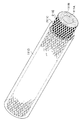
図4は本実施形態に係る加圧ロール111の断面図を表し、図5は図4に示される加圧ロールの接着層部分を表す斜視図である。
[Pressure member]
Here, a pressure roll as an example of a pressure member constituting the fixing device shown in FIG. 2 will be described.
FIG. 4 is a cross-sectional view of the
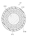
加圧ロール111は、芯金111Aと、芯金111Aの外周面に形成された弾性層111Bと、弾性層111Bの外周面に形成された離型層111Dと、弾性層111Bおよび離型層111Dを接着する接着剤層111Cと、を有する。
ここで、芯金111Aが本実施形態にいう円筒状の基材の一例に相当し、弾性層111Bが本実施形態にいう気泡を内在し弾性を有する第1の層の一例に相当し、離型層111Dが本実施形態にいう第2の層の一例に相当し、接着剤層111Cが本実施形態にいう接着剤層の一例に相当する。
The
Here, the cored
また加圧ロール111には、図5に示すごとく、弾性層111Bと離型層111Dとで挟まれる領域に、少なくとも軸方向の一端にまで接着剤が存在しない未接着領域111E、つまり接着剤が存在せず且つ少なくとも軸方向の一端にまで繋がる隙間を有する。尚、この未接着領域111Eは、図5に示すごとく、加圧ロール111の軸方向の一端から他端にまで繋がるものであることがより好ましい。
Further, as shown in FIG. 5, the
・芯金
芯金111Aには、例えば、ニッケル鍍金を施した鉄からなる直径18mmの円柱状の部材が用いられる。
-Core metal For the
・弾性層
弾性層111Bは、シリコーンゴム、フッ素ゴム、フルオロシリコンゴム等の発泡体で形成される。発泡剤としては、例えばアゾビスイソブチロニトリル(AIBN)、炭酸水素ナトリウム、炭酸アンモニウム、ジアゾアミノベンゼンなどが用いられる。
また、前記シリコーンゴム等の未加硫ゴムに対し各種発泡剤を加え加熱発泡させた発泡体にて形成する以外に、架橋反応ガスを発生する2成分型液状シリコーンゴムなどの自己発泡反応式の発泡ゴムも使用し得る。
弾性層111Bの内部には、多数の気泡が分散されており、気泡内部は空気などの気体で満たされている。弾性層111Bにおける発泡率は、120%以上250%以下であることが好ましい。
弾性層111Bは芯金の外周面のすべてを覆うよう形成され、その厚さは2mm以上20mm以下が好ましく、更には3mm以上10mm以下がより好ましい。
Elastic layer The
In addition to the formation of a foam obtained by adding various foaming agents to the unvulcanized rubber such as silicone rubber and heat-foaming, a self-foaming reaction formula such as a two-component liquid silicone rubber that generates a crosslinking reaction gas is used. Foam rubber can also be used.
Many bubbles are dispersed inside the
The
また、弾性層111Bには、気泡と、後述する未接着領域111E(弾性層111Bと離型層111Dとで挟まれる領域に形成され、少なくとも軸方向の一端にまで接着剤が存在しない領域)と、に繋がる切れ込みを有することが好ましい。尚、該切れ込みは、通常の状態では閉塞されており、弾性層111Bに熱が加えられると気泡内の空気の熱膨張によって広げられる形状を有する。切れ込みは、気泡と未接着領域111Eとを繋げる形状であれば、径方向に伸びる形状であっても、また径方向に対し斜め方向に伸びる形状であってもよい。
該切れ込みの形成は、例えば、芯金111A上に弾性層111Bを形成した後、該弾性層111Bに対し径方向や、径方向に対し斜め方向に、針や刃物を刺す等の方法によって形成し得る。
The
The cut is formed by, for example, a method in which an
尚、本実施形態では、弾性層111Bはシリコーンゴムの発泡体により、厚さ5mmの層として形成され、硬度が60°(Asker−C)となるよう調整されている。
In this embodiment, the
・離型層
離型層111Dは、PFA、PTFE、FEP等のフッ素樹脂、シリコン樹脂、シリコーンゴム、フッ素ゴム、フッ化ポリイミド等の離型性および耐熱性の良い材料で形成される。
離型層111Dは弾性層の外周面のすべてを覆うよう形成され、その厚さは10μm以上200μm以下が好ましく、更には20μm以上100μm以下がより好ましい。
尚、本実施形態では、離型層111DはPFAにより、厚さ30μmの層として形成されている。
-Release layer The
The
In the present embodiment, the
・接着剤層
前記弾性層111Bと離型層111Dとは接着剤層111Cにより接着されている。接着剤層111Cに用いられる接着剤としては、例えば湿気硬化型シリコーン接着剤、付加硬化型シリコーン接着剤、弗素ゴム系接着剤、エポキシ系接着剤等が挙げられる。尚、接着剤としては、弾性層111B上に塗布された際に垂れ落ちない粘度特性(チキソ性)を有するものが好ましい。
接着剤層111Cの厚さは、1μm以上300μm以下が好ましく、更には3μm以上100μm以下がより好ましい。
尚、本実施形態では、接着剤層111Cにおける接着剤として付加硬化型シリコーンゴム接着剤(東レダウコーニング社製、商品名SE1750)が用いられ、厚さ15μmの層として形成されている。
-Adhesive layer The
The thickness of the
In the present embodiment, an addition-curable silicone rubber adhesive (trade name SE1750, manufactured by Toray Dow Corning Co., Ltd.) is used as an adhesive in the
・未接着領域
尚、本実施形態における加圧ロール111では、弾性層111Bと離型層111Dとを接着する接着剤層111Cは、弾性層111Bの外周面すべてを覆うように塗布されるのではなく、接着剤が存在しない未接着領域を有する。つまり、図5に示されるごとく、弾性層111Bと離型層111Dとで挟まれる領域には、少なくとも軸方向の一端にまで接着剤が存在しない(より好ましくは軸方向の一端から他端にまで繋がる)未接着領域111Eを有する。尚、接着剤層111Cは、弾性層111Bの外周表面において軸方向の全領域にわたって周方向の少なくとも一部を覆うよう形成されていることが好ましい。
-Non-bonded area In the
図5に示される、軸方向に対して平行に伸びる未接着領域111E(隙間)は、その1つの隙間の幅が0.1mm以上10mm以下であることが好ましく、更には0.5mm以上5mm以下であることがより好ましい。
また、隙間と隙間との間隔は0.1mm以上10mm以下であることが好ましく、更には0.5mm以上5mm以下であることがより好ましく、またすべての隙間同士が等間隔で形成されていることが好ましい。
尚、本実施形態では、未接着領域111Eとして1つの隙間の幅が2mm、隙間と隙間との間隔は2mmの隙間を形成している。
In the
Moreover, it is preferable that the space | interval of a clearance gap is 0.1 mm or more and 10 mm or less, Furthermore, it is more preferable that it is 0.5 mm or more and 5 mm or less, and all the clearance gaps are formed at equal intervals. Is preferred.
In the present embodiment, the width of one gap is 2 mm as the
図5に示される、軸方向に対して平行に伸びる未接着領域111E(隙間)の形成方法としては、例えば以下の方法が挙げられる。
(1) 弾性層111Bを形成した芯金111Aの該弾性層111B上に、接着剤層111Cを形成するための接着剤を浸漬塗布し、その浸漬塗布の際にマスクを用いて塗布されない領域を設ける方法
As a method for forming the
(1) An adhesive for forming the
(2) シート上に定められた形状で接着剤が塗布された接着剤シートを準備し、弾性層111Bを形成した芯金111Aの該弾性層111B上に、上記接着剤シートから接着剤を転写塗布する方法
(2) An adhesive sheet coated with an adhesive in a predetermined shape is prepared on the sheet, and the adhesive is transferred from the adhesive sheet onto the
(3) 接着剤を吐出する吐出口と、芯金111Aの軸方向に沿って平行に移動する手段と、弾性層111Bを備えた芯金111Aを円周方向に回転させる手段と、を備える接着剤吐出装置を用い、接着剤を吐出すると共に弾性層111Bを備えた芯金111Aを軸方向に移動させる事によって、接着剤を弾性層111Bの外周に軸方向に対して平行に塗布し、更にこの動作を複数回繰り返す事によって弾性層111Bの外周全面に、定められた間隔で接着剤を塗布する方法
(3) Adhesion provided with a discharge port for discharging the adhesive, means for moving in parallel along the axial direction of the
(4) 接着剤を塗布する部分と同数の吐出口を弾性層111Bの外径よりわずかに大きな径で円周状に備える接着剤吐出装置を用い、接着剤を吐出すると共に吐出部を芯金111Aの軸方向に移動させるか、または吐出口を固定して弾性層111Bを備えた芯金111Aを軸方向に移動させる事によって、接着剤を弾性層111Bの外周に軸方向に対して平行に塗布する方法
(4) Using an adhesive discharge device provided with the same number of discharge ports as the portion to which the adhesive is applied, in a circumferential shape with a diameter slightly larger than the outer diameter of the
(5) 凹凸のない円筒状の基体の外周表面に前記(3)または(4)の方法によって軸方向に沿って接着剤を塗布したのち、この円筒状基体を弾性層111Bに回転させながら押しあて接着剤を転写する方法
(5) After applying an adhesive along the axial direction by the method of (3) or (4) above on the outer peripheral surface of a cylindrical base body without irregularities, the cylindrical base body is pushed while rotating to the
(6) 円筒状の基体の外周表面に軸方向に沿って溝(凹凸)を設け、この凹の部分に接着剤を塗布(凸の部分に接着剤はなし、または全面塗布ののち凸の部分のみ拭き取ってもよい)したのち、この円筒状基体を弾性層111Bに回転させながら押しあて接着剤を転写する方法
(6) A groove (unevenness) is provided along the axial direction on the outer peripheral surface of the cylindrical substrate, and an adhesive is applied to the recessed portion (there is no adhesive on the protruding portion, or only the protruding portion after the entire surface is applied) A method of transferring the adhesive by pressing the cylindrical substrate while rotating it on the
また、図5には、軸方向に対して平行に伸び軸方向の一端から他端にまで繋がる未接着領域111Eを示したが、本実施形態における未接着領域はこれに限定されるものではない。
他の未接着領域の態様としては、例えば図6に示すごとく、格子状に交差し軸方向の一端から他端にまで繋がる隙間を形成する未接着領域211Eの態様が挙げられる。図6に示される、格子状に交差し軸方向の一端から他端にまで繋がる未接着領域211Eにおいて、その1つの隙間の幅や、隙間と隙間との間隔については、前述の図5に示される軸方向に対して平行に伸びる隙間と同じ範囲が好適な範囲として挙げられる。
図6に示す格子状に交差し軸方向の一端から他端にまで繋がる隙間は、例えば、前述の(2)の方法や、円筒状の基体の表面に図6に示す格子状の溝(凹凸)を設け、この凹の部分に接着剤を塗布(凸の部分に接着剤はなし、または全面塗布ののち凸の部分のみ拭き取ってもよい)したのち、弾性層111Bに押し当てて接着剤を弾性層111Bの外周に転写塗布する方法等により形成し得る。
5 shows the
As another aspect of the unbonded region, for example, as illustrated in FIG. 6, there is a mode of an unbonded region 211 </ b> E that forms a gap that intersects in a lattice shape and is connected from one end to the other end in the axial direction. In the
The gap that intersects the lattice shape shown in FIG. 6 and is connected from one end to the other end in the axial direction is, for example, the method described in (2) above or a lattice-like groove (unevenness) shown in FIG. ) And apply the adhesive to the concave part (there is no adhesive on the convex part, or only the convex part may be wiped off after the entire surface is applied) and then pressed against the
更にそれ以外の未接着領域の態様としては、軸方向に対し螺旋状に伸び軸方向の一端から他端にまで繋がる未接着領域や、接着剤がドット状に塗布されそのドット状の接着剤同士の間に形成された未接着領域、等の態様が挙げられる。 Furthermore, as other aspects of the non-adhesive region, the non-adhesive region that extends spirally with respect to the axial direction and is connected from one end to the other end in the axial direction, and the dot-like adhesives that are applied in the form of dots. Examples of the non-adhered region formed between the two are included.
尚、弾性層111Bの外周表面の総面積(a)に対する、接着剤が塗布される総面積(b)の比率((b)/(a)×100)は、30%以上90%以下であることが好ましく、更には40%以上70%以下であることがより好ましい。
The ratio ((b) / (a) × 100) of the total area (b) to which the adhesive is applied to the total area (a) of the outer peripheral surface of the
・加圧部材の製造方法
加圧部材111は、例えば、まず円筒状の芯金111A上に弾性部材からなる層を設けた後、研削部材を用いて研削し求められる形状の弾性層111Bを形成する。次いで、形成された弾性層111Bに、針等を刺す方法により切れ込みを形成する。その後、前述の(1)乃至(6)に記載の方法等により接着剤を塗布し、その上から、弾性層111Bの外形よりも径の小さい離型層形成用のチューブを、拡径しながら被せ拡径を解いて弾性層111B上に被覆し、最後に接着剤を硬化させることで得られる。
-Pressure member manufacturing method For example, the
[作用]
上述したとおり、本実施形態に係る定着用加圧部材は、円筒状の基材と、前記基材の外周面上に、気泡を内在し弾性を有する第1の層と、前記第1の層の外周面上に、第2の層と、前記第1の層および前記第2の層を接着する接着剤層と、前記第1の層および前記第2の層で挟まれる領域に、少なくとも軸方向の一端にまで接着剤が存在しない未接着領域と、を有する。
[Action]
As described above, the fixing pressure member according to the present embodiment includes a cylindrical base material, a first layer having air bubbles on the outer peripheral surface of the base material, and elasticity, and the first layer. And at least a shaft in a region sandwiched between the second layer, the adhesive layer that bonds the first layer and the second layer, and the first layer and the second layer. And an unbonded area where no adhesive is present at one end in the direction.
定着装置に適用される定着用加圧部材(以下単に「加圧部材」と称す)には、定着装置稼働の際に対を成す加熱定着部材から熱が伝達され、この熱によって弾性を有する前記第1の層が熱膨張し加圧部材の外径が増加する。この熱膨張は、第1の層自体の熱膨張と、該第1の層が有する気泡の中の気体の熱膨張と、によるものと考えられる。
熱膨張を起こした気泡内の気体は、気圧が上昇することにより気泡の隔壁を透過し、最終的には加圧部材の軸方向端部から外部に放出される。しかし、加圧部材の軸方向中央部の気泡に含まれる気体は加圧部材の軸方向端部に到達するまで移動距離が長く外部に放出されるまでに時間を要する。そのため、定着装置を稼働させ加熱を開始した直後には特に加圧部材の軸方向中央部の外径が急激に増加し、その後気体の透過に伴って徐々に増加した分の外径が減少していくとの現象が見受けられた。
Heat is transmitted to a fixing pressure member (hereinafter simply referred to as “pressure member”) applied to the fixing device from a pair of heat fixing members when the fixing device is operated, and the heat has elasticity. The first layer expands thermally and the outer diameter of the pressure member increases. This thermal expansion is considered to be due to the thermal expansion of the first layer itself and the thermal expansion of the gas in the bubbles of the first layer.
The gas in the bubble that has undergone thermal expansion passes through the partition wall of the bubble as the atmospheric pressure increases, and is finally discharged to the outside from the axial end of the pressure member. However, the gas contained in the bubbles in the central portion in the axial direction of the pressurizing member has a long moving distance until it reaches the axial end of the pressurizing member, and it takes time to be released to the outside. Therefore, the outer diameter of the central portion in the axial direction of the pressure member increases rapidly immediately after the fixing device is operated and heating is started, and then the outer diameter is gradually increased as the gas permeates. The phenomenon of going on was seen.
尚、こうした定着装置稼動の際の加圧部材の外径の増大を抑える観点で、気泡を内在し弾性を有する第1の層に、軸方向に貫通する孔を周方向に多数設ける手段が考えられる。しかし、弾性を有する第1の層に軸方向に貫通孔を設けた場合、加熱定着部材に加圧部材を押し当てて形成される接触領域において、加圧部材の第1の層に前記貫通孔が存在する部分の圧力が低下するためトナーの熔融ムラが発生し、その結果定着後の画像では光沢ムラが生じることがあった。また、貫通孔が存在する部分の第1の層に応力が集中することから、第1の層の破断が発生しやすかった。 From the viewpoint of suppressing an increase in the outer diameter of the pressure member during the operation of the fixing device, a means for providing a large number of axially penetrating holes in the circumferential direction in the first layer containing bubbles and having elasticity is considered. It is done. However, when a through hole is provided in the first layer having elasticity in the axial direction, the through hole is formed in the first layer of the pressure member in a contact region formed by pressing the pressure member against the heat fixing member. Since the pressure in the portion where the toner exists is reduced, uneven melting of the toner occurs, and as a result, uneven gloss may occur in the image after fixing. In addition, since stress concentrates on the first layer in the portion where the through hole exists, the first layer is easily broken.
これに対し本実施形態に係る加圧部材は、気泡を内在し弾性を有する第1の層と第2の層とを接着する接着剤層を有し且つ該第1の層と第2の層とで挟まれる領域に少なくとも軸方向の一端にまで接着剤が存在しない未接着領域を有する。そのため、加圧部材に熱が加えられ第1の層の気泡内の気体が熱膨張した際にも、該気体は気泡の隔壁を透過して前記未接着領域に到達した後に該未接着領域を通って軸方向端部にまで容易に到達し外部に放出されるため、加圧部材の外径の増大が抑制される。
更に、定着装置の加熱定着部材に加圧部材を押し当てて形成される接触領域においても、特に加圧部材の押し当てる場所によって圧力の低下が生じることがないため、トナーの熔融ムラが抑制され、その結果定着後の画像における光沢ムラの発生が抑制される。
また、加圧部材の第1の層においても特定の箇所に応力が集中することがないため、第1の層の破断の発生も抑制され耐久性に優れる。
On the other hand, the pressurizing member according to the present embodiment has an adhesive layer that adheres the first layer and the second layer having air bubbles and has elasticity, and the first layer and the second layer. And an unbonded region where no adhesive is present at least at one end in the axial direction. Therefore, even when heat is applied to the pressure member and the gas in the bubbles in the first layer thermally expands, the gas passes through the partition walls of the bubbles and reaches the unbonded region. Since it easily reaches the axial end and is discharged to the outside, an increase in the outer diameter of the pressure member is suppressed.
Further, even in the contact region formed by pressing the pressure member against the heat fixing member of the fixing device, the pressure does not drop depending on the location where the pressure member is pressed, so that uneven toner melting is suppressed. As a result, the occurrence of uneven gloss in the image after fixing is suppressed.
Moreover, since stress does not concentrate on a specific location in the first layer of the pressure member, the occurrence of breakage of the first layer is suppressed, and the durability is excellent.
尚、本実施形態において前記第1の層は、前記気泡および前記未接着領域と繋がり且つ径方向に伸びる切れ込みを有することが好ましい。
前記切れ込みは、第1の層に特に熱が加えられていない状態では閉塞されているが、該第1の層に熱が加えられると熱膨張によって切れ込みが広げられる。そのため、第1の層の気泡に存在する気体はこの広げられた切れ込みを通って第1の層と第2の層とで挟まれる領域に存在する未接着領域に到達するため、隔壁を透過する場合よりも早く気体の移動が行われる。その結果、第1の層に切れ込みを有しない場合に比べて、より一層気泡内の気体の外部への放出が円滑に行われ、加圧部材の外径の増大がより効率的に抑制される。
In the present embodiment, it is preferable that the first layer has a notch that is connected to the bubbles and the non-bonded region and extends in the radial direction.
The cut is blocked when no heat is applied to the first layer. However, when heat is applied to the first layer, the cut is widened by thermal expansion. Therefore, the gas existing in the bubbles in the first layer reaches the unbonded region existing in the region sandwiched between the first layer and the second layer through this widened cut, and thus passes through the partition wall. The gas moves faster than the case. As a result, compared with the case where the first layer has no cut, the gas inside the bubbles is more smoothly discharged to the outside, and the increase in the outer diameter of the pressure member is more efficiently suppressed. .
また、本実施形態においては、第1の層と第2の層とで挟まれる領域に存在する前記未接着領域が、軸方向の一端から他端にまで繋がることが好ましい。
前記未接着領域が軸方向の一端から他端にまで繋がるため、未接着領域が軸方向の一端にのみ繋がる場合に比べて、より一層気泡内の気体の外部への放出が円滑に行われ、加圧部材の外径の増大がより効率的に抑制される。
Moreover, in this embodiment, it is preferable that the said non-bonding area | region which exists in the area | region pinched | interposed by a 1st layer and a 2nd layer is connected from one end to the other end of an axial direction.
Since the non-bonded region is connected from one end to the other end in the axial direction, compared to the case where the non-bonded region is connected only to one end in the axial direction, the gas inside the bubbles is more smoothly discharged to the outside. An increase in the outer diameter of the pressure member is more efficiently suppressed.
[変形例]
尚、図面を用いて、上記の通り本実施形態に係る定着用加圧部材や定着装置、画像形成装置について説明したが、本実施形態はこれらに限定されるものではない。
例えば、加圧部材における接着剤層111Cは、弾性層111Bの外周表面において軸方向の全領域にわたって周方向の少なくとも一部を覆うよう形成されていなくともよい。但し、弾性層111Bと離型層111Dとの剥離を効率的に抑制する観点から、軸方向の全領域にわたって周方向の少なくとも一部を覆うよう形成されていることが好ましい。
[Modification]
Although the fixing pressure member, the fixing device, and the image forming apparatus according to the present embodiment have been described with reference to the drawings as described above, the present embodiment is not limited thereto.
For example, the
また、弾性層111Bと離型層111Dとで挟まれる領域に形成される未接着領域は、軸方向の少なくとも一端にまで繋がっていればよく、更には軸方向の中央部から一端にまで繋がっていることがより好ましく、軸方向の一端から他端にまで繋がっていることが更に好ましい。
Further, the non-bonded region formed in the region sandwiched between the
また、弾性層111B上に接着剤層111Cを介して離型層111Dを設けた態様について説明したが、弾性層111B上に接着剤層111Cを介して中間層を設け該中間層の外周側に離型層111Dを形成した態様であってもよい。
Moreover, although the aspect which provided the
また、上述した実施形態では、本実施形態にいう加熱定着部材の例として、圧力部材113によって加圧ロール111に押し付けられる加熱定着ベルト110を示したが、本実施形態はこれに限られるものではなく、加熱定着部材として加熱定着ロールを適用した態様であってもよい。
In the above-described embodiment, the
また、上述した実施形態では、記録媒体として用紙Pを適用する例を示したが、本実施形態にいう記録媒体は用紙に限られず、種々の用途のシートが用いられる。また、その枚数としては、1枚でもよいし、ラミネートシートを作製する場合のように複数枚であってもよい。 In the above-described embodiment, an example in which the sheet P is applied as the recording medium has been described. However, the recording medium in the present embodiment is not limited to the sheet, and sheets for various purposes are used. Further, the number of sheets may be one, or a plurality of sheets as in the case of producing a laminate sheet.
また、上述した実施形態では、画像形成装置の例としてタンデム型のカラープリンタを示したが、本実施形態にいう画像形成装置はこれに限られず、例えば、中間転写ベルトを有しないモノクロ専用プリンタであってもよい。 In the above-described embodiment, a tandem type color printer is shown as an example of the image forming apparatus. However, the image forming apparatus referred to in this embodiment is not limited to this, and is, for example, a monochrome printer having no intermediate transfer belt. There may be.
また、上述した実施形態では、画像形成装置の例としてプリンタを示したが、本実施形態にいう画像形成装置はプリンタに限られず、例えば、画像読取装置で読み取られたデータに基づいて画像を形成する複写機やファクシミリであってもよい。 In the embodiment described above, a printer is shown as an example of the image forming apparatus. However, the image forming apparatus referred to in the present embodiment is not limited to a printer, and for example, an image is formed based on data read by an image reading apparatus. It may be a copying machine or a facsimile machine.
[試験例1]
以下に、上記のごとく構成された定着装置の性能評価試験の結果を示す。尚、本実施形態に係る定着用加圧部材、定着装置、および画像形成装置は、以下の態様に限定されるものではない。
[Test Example 1]
The results of the performance evaluation test of the fixing device configured as described above are shown below. The fixing pressure member, the fixing device, and the image forming apparatus according to the present embodiment are not limited to the following modes.
試験においては、図5に示す加圧ロール111を、図2に示すごとく60kgfの荷重で加熱定着ベルト110に押し当てた。
また、比較例1の加圧ロールとして、図7に示す通り、芯金311Aと、芯金311Aの外周面に形成された弾性層311Bと、弾性層311Bの外周面に形成された離型層311Dと、を有し、弾性層311Bの軸方向一端から他端まで貫通した通気孔311Eが設けられた加圧ロール311を用いた。尚、この通気孔311Eは、加熱定着ベルト110からの熱が伝達されていない状態での直径が1mmの円形をなし、この通気孔311Eが加圧ロール311の表面から芯金311Aの中心に向かって2.5mmの位置に、周方向に等間隔で18本設けられている。
In the test, the
Moreover, as a pressure roll of the comparative example 1, as shown in FIG. 7, the cored
本実施形態に係る図5に示す加圧ロール111を搭載した定着装置と、比較例1の加圧ロール311を搭載した定着装置とで、トナー量が10g/m2の濃度で塗りつぶされた画像を、各加圧ロールの周速度80mm/sで定着させた。
その結果、比較例1の加圧部材311を使用した場合には、弾性層311Bの前記通気孔311Eに対応した筋状の目視で確認し得る光沢ムラが画像に発生した。一方、本実施形態の加圧ロール111を使用した場合には、目視で確認し得るレベルの光沢ムラは発生しなかった。
An image in which the toner amount is filled with a density of 10 g / m 2 by the fixing device equipped with the
As a result, when the pressurizing
[試験例2]
次に、熱膨張による加圧ロールの外径の変化を調べる試験を行った。
この試験では、本実施形態に係る図5に示す加圧ロール111と、上記比較例1に係る加圧ロール311と、に加え、比較例1の加圧ロールにおいて弾性層311Bに通気孔311Eが設けられていない加圧ロール(比較例2)を用いて対比を行った。
各加圧ロールを60rpmで回転させると共に、ハロゲンランプで内面を加熱して外周面の温度を170℃とした円筒状の加熱定着ベルトを回転状態で押し当て、加圧ロールの表面を170℃保つと共に、レーザー式外径測定機によって加圧ロール中央部の、室温(25℃)の際の外径からの外径膨張量の測定を行った。
[Test Example 2]
Next, a test for examining a change in the outer diameter of the pressure roll due to thermal expansion was performed.
In this test, in addition to the
Each pressure roll is rotated at 60 rpm, and a cylindrical heat-fixing belt whose inner surface is heated by a halogen lamp and whose outer peripheral surface temperature is 170 ° C. is pressed in a rotating state to keep the pressure roll surface at 170 ° C. At the same time, the outer diameter expansion amount from the outer diameter at the room temperature (25 ° C.) of the central portion of the pressure roll was measured by a laser type outer diameter measuring machine.
この結果、外径膨張量は、本実施形態に係る加圧ロール111は0.83mm、比較例1に係るに係る加圧ロール311は0.85mm、比較例2に係るに係る加圧ロールは1.7mmであった。
As a result, the outer diameter expansion amount is 0.83 mm for the
1Y,1M,1C,1K 画像形成ユニット
10 1次転写部
11 感光体ドラム
12 帯電器
13 レーザ露光器
14 現像器
15 中間転写ベルト
16 1次転写ロール
17 ドラムクリーナ
20 2次転写部
22 2次転写ロール
25 背面ロール
26 給電ロール
31 駆動ロール
32 支持ロール
33 張力ロール
34 クリーニング部背面ロール
35 中間転写ベルトクリーナ
40 制御部
43 画像濃度センサ
50 用紙収容部
51 取り出しロール
52 搬送ロール
53 案内部材
55 搬送ベルト
56 定着入口ガイド
60 定着装置
100 画像形成装置
110 加熱定着ベルト
111 加圧ロール
111A 芯金
111B 弾性層
111C,211C 接着剤層
111D 離型層
111E,211E 未接着領域
112 磁場発生装置
113 圧力部材
113A ホルダ
113B 圧力パッド
114 トナー像
311 加圧ロール
311A 芯金
311B 弾性層
311D 離型層
311E 通気孔
801 保持部
802 フランジ
803 円筒部
P 用紙
1Y, 1M, 1C, 1K
Claims (6)
前記基材の外周面上に、気泡が内在し弾性を有する第1の層と、
前記第1の層の外周面上に、第2の層と、
前記第1の層および前記第2の層を接着する接着剤層と、
前記第1の層および前記第2の層で挟まれる領域に、少なくとも軸方向の一端にまで接着剤が存在しない未接着領域と、
を有する定着用加圧部材。 A cylindrical substrate;
On the outer peripheral surface of the substrate, a first layer having bubbles and having elasticity,
On the outer peripheral surface of the first layer, a second layer;
An adhesive layer for bonding the first layer and the second layer;
An unbonded region where no adhesive is present at least at one end in the axial direction in a region sandwiched between the first layer and the second layer;
A pressure member for fixing.
加熱装置と、
前記加熱装置により加熱され、前記定着用加圧部材を押し当てられて該定着用加圧部材との間に接触領域を形成し、該接触領域にトナー像が表面に形成された記録媒体を挟んで周回移動し前記トナー像を加熱および加圧して定着する加熱定着部材と、
を有する定着装置。 A fixing pressure member according to claim 1;
A heating device;
Heated by the heating device and pressed against the fixing pressure member to form a contact area with the fixing pressure member, and a recording medium having a toner image formed on the surface is sandwiched between the contact areas. A heating fixing member that moves around and heats and pressurizes and fixes the toner image;
A fixing device.
請求項5に記載の定着装置と、
前記トナー像の形成された前記記録媒体を前記加熱部材と前記定着用加圧部材との接触領域に搬送する搬送装置と、
を有する画像形成装置。 A toner image forming unit that forms a toner image and transfers the toner image onto a recording medium;
A fixing device according to claim 5;
A conveying device that conveys the recording medium on which the toner image is formed to a contact area between the heating member and the fixing pressure member;
An image forming apparatus.
Priority Applications (2)
| Application Number | Priority Date | Filing Date | Title |
|---|---|---|---|
| JP2012069962A JP2013200505A (en) | 2012-03-26 | 2012-03-26 | Pressure member for fixing, fixing device, and image forming apparatus |
| US13/616,351 US8913939B2 (en) | 2012-03-26 | 2012-09-14 | Pressing member for fixing, fixing device, and image-forming apparatus |
Applications Claiming Priority (1)
| Application Number | Priority Date | Filing Date | Title |
|---|---|---|---|
| JP2012069962A JP2013200505A (en) | 2012-03-26 | 2012-03-26 | Pressure member for fixing, fixing device, and image forming apparatus |
Publications (2)
| Publication Number | Publication Date |
|---|---|
| JP2013200505A true JP2013200505A (en) | 2013-10-03 |
| JP2013200505A5 JP2013200505A5 (en) | 2015-07-30 |
Family
ID=49211929
Family Applications (1)
| Application Number | Title | Priority Date | Filing Date |
|---|---|---|---|
| JP2012069962A Pending JP2013200505A (en) | 2012-03-26 | 2012-03-26 | Pressure member for fixing, fixing device, and image forming apparatus |
Country Status (2)
| Country | Link |
|---|---|
| US (1) | US8913939B2 (en) |
| JP (1) | JP2013200505A (en) |
Cited By (2)
| Publication number | Priority date | Publication date | Assignee | Title |
|---|---|---|---|---|
| WO2019082955A1 (en) * | 2017-10-26 | 2019-05-02 | 株式会社ブリヂストン | Development roller and development roller manufacturing method |
| CN112799290A (en) * | 2019-11-13 | 2021-05-14 | 株式会社金阳社 | Silicon sponge roller for fixing device and heating fixing device |
Families Citing this family (3)
| Publication number | Priority date | Publication date | Assignee | Title |
|---|---|---|---|---|
| JP2013200505A (en) * | 2012-03-26 | 2013-10-03 | Fuji Xerox Co Ltd | Pressure member for fixing, fixing device, and image forming apparatus |
| JP2019164266A (en) * | 2018-03-20 | 2019-09-26 | 富士ゼロックス株式会社 | Pressure member for fixing, fixing device, and image forming apparatus |
| US20190351624A1 (en) * | 2018-05-16 | 2019-11-21 | GM Global Technology Operations LLC | Systems and processes for repairing fiber-reinforced polymer structures |
Citations (6)
| Publication number | Priority date | Publication date | Assignee | Title |
|---|---|---|---|---|
| JPH02119662U (en) * | 1989-03-14 | 1990-09-26 | ||
| JPH0442183A (en) * | 1990-06-08 | 1992-02-12 | Arai Pump Mfg Co Ltd | Pressure roller for fixation and its manufacture |
| JPH06337610A (en) * | 1993-05-27 | 1994-12-06 | Arai Pump Mfg Co Ltd | Press roller |
| JP2005043476A (en) * | 2003-07-23 | 2005-02-17 | Toshiba Corp | Fixing device for image forming apparatus and image forming apparatus |
| JP2007248690A (en) * | 2006-03-15 | 2007-09-27 | Konica Minolta Business Technologies Inc | Fixing device and image forming apparatus |
| JP2008292933A (en) * | 2007-05-28 | 2008-12-04 | Ricoh Co Ltd | Fixing roller, manufacturing method thereof and fixing device having the fixing roller |
Family Cites Families (15)
| Publication number | Priority date | Publication date | Assignee | Title |
|---|---|---|---|---|
| EP0322127B1 (en) * | 1987-12-04 | 1994-02-02 | Canon Kabushiki Kaisha | Rotatable member for fixing apparatus and fixing apparatus using same |
| JPH02150876A (en) * | 1988-12-02 | 1990-06-11 | Canon Inc | Elastic rotating body and fixation device |
| JPH0749631A (en) * | 1993-08-04 | 1995-02-21 | Sumitomo Electric Ind Ltd | Fixing roller |
| DE10161744A1 (en) * | 2001-12-15 | 2003-06-18 | Werner Jahn | Cling type plastic fastener strip manufacture involves pin creation by compression of plastic strip into holes in a rubber cover on a metal roll then shaping of heads on pins |
| JP4459554B2 (en) | 2002-07-19 | 2010-04-28 | シンジーテック株式会社 | Fixing roller |
| JP4459555B2 (en) | 2002-07-19 | 2010-04-28 | シンジーテック株式会社 | Fixing roller |
| JP2005202144A (en) * | 2004-01-15 | 2005-07-28 | Oki Data Corp | Fixing device and method for manufacturing fixing member |
| JP4650166B2 (en) * | 2005-03-23 | 2011-03-16 | 富士ゼロックス株式会社 | Fixing member, fixing device, and image forming apparatus |
| JP2008003265A (en) * | 2006-06-22 | 2008-01-10 | Seiko:Kk | Silicone rubber roll, thermal fixing roller and its manufacturing method |
| JP4052342B2 (en) * | 2006-08-07 | 2008-02-27 | 富士ゼロックス株式会社 | Roller, fixing device and image forming apparatus |
| JP2008158332A (en) | 2006-12-25 | 2008-07-10 | Swcc Showa Device Technology Co Ltd | Fixing member and method of manufacturing the same |
| JP5439993B2 (en) * | 2008-11-13 | 2014-03-12 | 株式会社リコー | FIXING MEMBER, MANUFACTURING METHOD THEREFOR, FIXING DEVICE AND IMAGE FORMING DEVICE |
| US8600276B2 (en) * | 2010-01-27 | 2013-12-03 | Ricoh Company, Limited | Heat conduction unit, fixing device, and image forming apparatus |
| JP2013200410A (en) * | 2012-03-23 | 2013-10-03 | Fuji Xerox Co Ltd | Fixing belt, fixing device, and image forming apparatus |
| JP2013200505A (en) * | 2012-03-26 | 2013-10-03 | Fuji Xerox Co Ltd | Pressure member for fixing, fixing device, and image forming apparatus |
-
2012
- 2012-03-26 JP JP2012069962A patent/JP2013200505A/en active Pending
- 2012-09-14 US US13/616,351 patent/US8913939B2/en not_active Expired - Fee Related
Patent Citations (6)
| Publication number | Priority date | Publication date | Assignee | Title |
|---|---|---|---|---|
| JPH02119662U (en) * | 1989-03-14 | 1990-09-26 | ||
| JPH0442183A (en) * | 1990-06-08 | 1992-02-12 | Arai Pump Mfg Co Ltd | Pressure roller for fixation and its manufacture |
| JPH06337610A (en) * | 1993-05-27 | 1994-12-06 | Arai Pump Mfg Co Ltd | Press roller |
| JP2005043476A (en) * | 2003-07-23 | 2005-02-17 | Toshiba Corp | Fixing device for image forming apparatus and image forming apparatus |
| JP2007248690A (en) * | 2006-03-15 | 2007-09-27 | Konica Minolta Business Technologies Inc | Fixing device and image forming apparatus |
| JP2008292933A (en) * | 2007-05-28 | 2008-12-04 | Ricoh Co Ltd | Fixing roller, manufacturing method thereof and fixing device having the fixing roller |
Cited By (6)
| Publication number | Priority date | Publication date | Assignee | Title |
|---|---|---|---|---|
| WO2019082955A1 (en) * | 2017-10-26 | 2019-05-02 | 株式会社ブリヂストン | Development roller and development roller manufacturing method |
| CN111279273A (en) * | 2017-10-26 | 2020-06-12 | 株式会社普利司通 | Developing roller and method for manufacturing developing roller |
| JPWO2019082955A1 (en) * | 2017-10-26 | 2020-12-03 | 株式会社ブリヂストン | Development roller and manufacturing method of development roller |
| JP7177783B2 (en) | 2017-10-26 | 2022-11-24 | 株式会社アーケム | Developing roller and method for manufacturing developing roller |
| CN112799290A (en) * | 2019-11-13 | 2021-05-14 | 株式会社金阳社 | Silicon sponge roller for fixing device and heating fixing device |
| JP2021076801A (en) * | 2019-11-13 | 2021-05-20 | 株式会社金陽社 | Silicone sponge roller for fixing device, and heat fixing device |
Also Published As
| Publication number | Publication date |
|---|---|
| US20130251427A1 (en) | 2013-09-26 |
| US8913939B2 (en) | 2014-12-16 |
Similar Documents
| Publication | Publication Date | Title |
|---|---|---|
| US8195076B2 (en) | Fixing device and image forming apparatus including same | |
| JP2008065264A (en) | Fixing device and image forming apparatus | |
| JP5343343B2 (en) | Fixing apparatus and image forming apparatus | |
| JP2013200505A (en) | Pressure member for fixing, fixing device, and image forming apparatus | |
| JP6979164B2 (en) | Fixing device, image forming device | |
| JP4551932B2 (en) | Fixing device and image forming apparatus having the same | |
| JP2009109648A (en) | Fixing device and image forming apparatus | |
| JP5515226B2 (en) | Fixing apparatus and image forming apparatus | |
| US8295750B2 (en) | Fixing apparatus and image forming apparatus equipped therewith | |
| JP2005077872A (en) | Fixing device and image forming apparatus | |
| JP4711320B2 (en) | Fixing apparatus and image forming apparatus having the fixing apparatus | |
| JP6766545B2 (en) | Fixing device, image forming device | |
| JP5076806B2 (en) | Fixing apparatus and image forming apparatus | |
| JP4335262B2 (en) | Evaluation method of fixing roller | |
| JP2015075633A (en) | Pressure member, fixing device, and image forming apparatus | |
| JP2005156918A (en) | Fixing device | |
| JP2009186563A (en) | Fixing device and image forming apparatus | |
| JP2014191024A (en) | Pressure member for fixation, fixing device, and image forming apparatus | |
| JP6226230B2 (en) | Fixing apparatus and image forming apparatus | |
| JP3251816B2 (en) | Fixing film and image heating device | |
| JP2018054731A (en) | Belt member, fixation device and image formation device | |
| JP2016142993A (en) | Fixing member, fixing device, and image forming apparatus | |
| JP2015227910A (en) | Roller, fixing roller, fixing apparatus, and image forming apparatus | |
| JP2015152824A (en) | image heating device | |
| JP2014081443A (en) | Fixing apparatus and image forming apparatus |
Legal Events
| Date | Code | Title | Description |
|---|---|---|---|
| A621 | Written request for application examination |
Free format text: JAPANESE INTERMEDIATE CODE: A621 Effective date: 20150210 |
|
| A521 | Request for written amendment filed |
Free format text: JAPANESE INTERMEDIATE CODE: A523 Effective date: 20150615 |
|
| A131 | Notification of reasons for refusal |
Free format text: JAPANESE INTERMEDIATE CODE: A131 Effective date: 20151215 |
|
| A977 | Report on retrieval |
Free format text: JAPANESE INTERMEDIATE CODE: A971007 Effective date: 20151216 |
|
| A521 | Request for written amendment filed |
Free format text: JAPANESE INTERMEDIATE CODE: A523 Effective date: 20160212 |
|
| A131 | Notification of reasons for refusal |
Free format text: JAPANESE INTERMEDIATE CODE: A131 Effective date: 20160510 |
|
| A521 | Request for written amendment filed |
Free format text: JAPANESE INTERMEDIATE CODE: A523 Effective date: 20160711 |
|
| A02 | Decision of refusal |
Free format text: JAPANESE INTERMEDIATE CODE: A02 Effective date: 20161122 |