JP2013199925A - Gas turbine equipment - Google Patents
Gas turbine equipment Download PDFInfo
- Publication number
- JP2013199925A JP2013199925A JP2012237136A JP2012237136A JP2013199925A JP 2013199925 A JP2013199925 A JP 2013199925A JP 2012237136 A JP2012237136 A JP 2012237136A JP 2012237136 A JP2012237136 A JP 2012237136A JP 2013199925 A JP2013199925 A JP 2013199925A
- Authority
- JP
- Japan
- Prior art keywords
- compressed air
- heat
- gas
- line
- transfer medium
- Prior art date
- Legal status (The legal status is an assumption and is not a legal conclusion. Google has not performed a legal analysis and makes no representation as to the accuracy of the status listed.)
- Pending
Links
- 239000002737 fuel gas Substances 0.000 claims abstract description 167
- 239000007789 gas Substances 0.000 claims abstract description 156
- XLYOFNOQVPJJNP-UHFFFAOYSA-N water Substances O XLYOFNOQVPJJNP-UHFFFAOYSA-N 0.000 claims abstract description 106
- 238000001816 cooling Methods 0.000 claims abstract description 89
- 238000012546 transfer Methods 0.000 claims description 104
- 239000000446 fuel Substances 0.000 claims description 57
- 238000011084 recovery Methods 0.000 claims description 51
- 239000012530 fluid Substances 0.000 claims description 12
- 239000000567 combustion gas Substances 0.000 claims description 10
- 239000007788 liquid Substances 0.000 claims description 10
- 238000005192 partition Methods 0.000 claims description 8
- 239000002918 waste heat Substances 0.000 abstract description 10
- 230000006835 compression Effects 0.000 abstract description 3
- 238000007906 compression Methods 0.000 abstract description 3
- 239000000203 mixture Substances 0.000 abstract description 3
- 238000011144 upstream manufacturing Methods 0.000 description 12
- 238000010586 diagram Methods 0.000 description 11
- 239000003921 oil Substances 0.000 description 4
- 230000007812 deficiency Effects 0.000 description 3
- IJGRMHOSHXDMSA-UHFFFAOYSA-N Atomic nitrogen Chemical compound N#N IJGRMHOSHXDMSA-UHFFFAOYSA-N 0.000 description 2
- CURLTUGMZLYLDI-UHFFFAOYSA-N Carbon dioxide Chemical compound O=C=O CURLTUGMZLYLDI-UHFFFAOYSA-N 0.000 description 2
- FGIUAXJPYTZDNR-UHFFFAOYSA-N potassium nitrate Chemical compound [K+].[O-][N+]([O-])=O FGIUAXJPYTZDNR-UHFFFAOYSA-N 0.000 description 2
- VWDWKYIASSYTQR-UHFFFAOYSA-N sodium nitrate Chemical compound [Na+].[O-][N+]([O-])=O VWDWKYIASSYTQR-UHFFFAOYSA-N 0.000 description 2
- LPXPTNMVRIOKMN-UHFFFAOYSA-M sodium nitrite Chemical compound [Na+].[O-]N=O LPXPTNMVRIOKMN-UHFFFAOYSA-M 0.000 description 2
- 239000000126 substance Substances 0.000 description 2
- JIAARYAFYJHUJI-UHFFFAOYSA-L zinc dichloride Chemical compound [Cl-].[Cl-].[Zn+2] JIAARYAFYJHUJI-UHFFFAOYSA-L 0.000 description 2
- PKQYSCBUFZOAPE-UHFFFAOYSA-N 1,2-dibenzyl-3-methylbenzene Chemical compound C=1C=CC=CC=1CC=1C(C)=CC=CC=1CC1=CC=CC=C1 PKQYSCBUFZOAPE-UHFFFAOYSA-N 0.000 description 1
- ATJFFYVFTNAWJD-UHFFFAOYSA-N Tin Chemical compound [Sn] ATJFFYVFTNAWJD-UHFFFAOYSA-N 0.000 description 1
- 238000009835 boiling Methods 0.000 description 1
- 239000001569 carbon dioxide Substances 0.000 description 1
- 229910002092 carbon dioxide Inorganic materials 0.000 description 1
- 238000002485 combustion reaction Methods 0.000 description 1
- 239000000470 constituent Substances 0.000 description 1
- 239000002826 coolant Substances 0.000 description 1
- 238000013461 design Methods 0.000 description 1
- 238000010438 heat treatment Methods 0.000 description 1
- 229910052734 helium Inorganic materials 0.000 description 1
- 239000001307 helium Substances 0.000 description 1
- SWQJXJOGLNCZEY-UHFFFAOYSA-N helium atom Chemical compound [He] SWQJXJOGLNCZEY-UHFFFAOYSA-N 0.000 description 1
- 238000007689 inspection Methods 0.000 description 1
- 238000009434 installation Methods 0.000 description 1
- 229910001338 liquidmetal Inorganic materials 0.000 description 1
- 239000000463 material Substances 0.000 description 1
- 238000005259 measurement Methods 0.000 description 1
- 238000012986 modification Methods 0.000 description 1
- 230000004048 modification Effects 0.000 description 1
- 229910052757 nitrogen Inorganic materials 0.000 description 1
- 238000013021 overheating Methods 0.000 description 1
- 230000000149 penetrating effect Effects 0.000 description 1
- 239000004323 potassium nitrate Substances 0.000 description 1
- 235000010333 potassium nitrate Nutrition 0.000 description 1
- 238000002360 preparation method Methods 0.000 description 1
- 239000004317 sodium nitrate Substances 0.000 description 1
- 235000010344 sodium nitrate Nutrition 0.000 description 1
- 235000010288 sodium nitrite Nutrition 0.000 description 1
- 229910000679 solder Inorganic materials 0.000 description 1
- 230000003068 static effect Effects 0.000 description 1
- 235000005074 zinc chloride Nutrition 0.000 description 1
- 239000011592 zinc chloride Substances 0.000 description 1
Images


Abstract
Description
本発明はガスタービン設備に関するものであり、タービン翼冷却用の圧縮空気の冷却と燃料ガスの予熱を同時に効果的に行うことができるように工夫したものである。 The present invention relates to gas turbine equipment, and is devised so that compressed air for cooling turbine blades and fuel gas preheating can be effectively performed simultaneously.
従来のガスタービン設備の一例を、図12を参照して説明する。
このガスタービン設備1は、ガスタービン10や排熱回収ボイラー20などを備えている。
An example of conventional gas turbine equipment will be described with reference to FIG.
The gas turbine facility 1 includes a
ガスタービン10は、圧縮機11と燃焼器12とタービン13を主要部材として構成されている。圧縮機11は空気Aを圧縮して圧縮空気A1を燃焼器12に送る。燃焼器12では、圧縮機11から圧縮空気A1が送られると共に、燃料ラインL1を通して燃料ガスFが供給され、燃料ガスFを燃焼させて高温・高圧の燃焼ガスBを発生する。この高温・高圧の燃焼ガスBがタービン13で膨張してタービン13が回転駆動し、タービン13の回転力により発電機(図示省略)を回転して発電が行われる。
The
排熱回収ボイラー(HRSG:heat recovery steam generator)20は、タービン13から排出される高温・高圧の排気ガスEのエネルギーを回収し、回収した熱により高温・高圧の蒸気を発生させ、この蒸気により蒸気タービン(図示省略)を回転させている。
A heat recovery steam generator (HRSG) 20 recovers the energy of the high-temperature and high-pressure exhaust gas E discharged from the
このようなガスタービン設備1において、ガスタービン10の出力を増大し、また大きな効率を得るために、タービン13の入口における作動媒体(燃焼ガスB)の温度は千数百度という高温になっている。このような高いタービン入口温度は、タービン翼の耐熱性に関する材料上の問題を生じさせるため、通常ではタービン翼表面の冷却を実施する。
In such a gas turbine facility 1, the temperature of the working medium (combustion gas B) at the inlet of the
その冷却のために使用される冷却媒体としては、圧縮機11で圧縮された空気を分岐した圧縮空気A2を用いており、この圧縮空気A2を冷却空気冷却器15で冷却し、冷却した圧縮空気A2によりタービン13のタービン翼の冷却をしている。
As the cooling medium used for the cooling, compressed air A2 obtained by branching the air compressed by the
冷却空気冷却器15は、圧縮空気ラインL4及び排熱回収ボイラー20に水W1を給水する給水ラインL2に接続されており、水W1により圧縮空気A2の冷却をしている。
冷却空気冷却器15に供給される水W1の温度は、例えば100〜150℃であり、圧縮機11から冷却空気冷却器15に供給される圧縮空気A2の温度は、例えば400〜450℃であり、圧縮空気A2を水W1により冷却している。
The
The temperature of the water W1 supplied to the
また、ガスタービン10では、一般に燃料ガスFと圧縮空気A1との混合物を使用して燃焼するが、燃料ガスFの温度が低い場合には、燃料温度を上昇させるためにエネルギーの一部が使用されるため、ガスタービン10の性能を低下させると共に効率を低下させることになる。そのため、燃焼前に燃料を予熱することが望ましい。
The
その予熱のために使用される加熱媒体としては、給水ラインL3を通して排熱回収ボイラー20に送られる水W2を用いており、燃料ガスFを燃料ガス加熱器16で予熱している。
As a heating medium used for the preheating, water W2 sent to the exhaust
燃料ガス加熱器16は、給水ラインL3に接続されており、水W2により燃料ガスFの予熱をしている。
燃料ガス加熱器16に供給される水W2の温度は、例えば150〜200℃であり、燃料ガスFを水W2により予熱している。
The
The temperature of the water W2 supplied to the
なお、燃料ガスFの予熱のために、補助ボイラー等を設置する例もある。 There is also an example in which an auxiliary boiler or the like is installed for preheating the fuel gas F.
ところで上記従来技術では、圧縮空気A2を冷却する冷却系統と、燃料Fを予熱する予熱系統が、独立した別の系統であるため、熱の有効利用をすることができなかった。 By the way, in the said prior art, since the cooling system which cools compressed air A2, and the preheating system which preheats the fuel F are another independent systems, it was not possible to make effective use of heat.
また図12に示すように、排熱回収ボイラー20に送られる水W1、即ち、蒸気タービンサイクル側の給水を用いて圧縮空気A2の冷却をし、排熱回収ボイラー20に送られる水W2、即ち、蒸気タービンサイクル側の給水を用いて燃料Fの予熱をしている場合には、排熱回収ボイラーを含むプラントの起動時において、圧縮空気A2の冷却や燃料Fの予熱の調整が難しいという問題がある。
また、検査等により蒸気タービン側が停止して、ガスタービン側が単独運転する場合には、水W1による圧縮空気A2の冷却や、水W2による燃料Fの予熱ができなくなる。
Further, as shown in FIG. 12, the water W1 sent to the exhaust
Further, when the steam turbine side is stopped by inspection or the like and the gas turbine side is operated alone, the compressed air A2 cannot be cooled by the water W1 and the fuel F cannot be preheated by the water W2.
本発明は、上記従来技術に鑑み、ガスタービン側が単独運転していても熱の有効利用をしつつ、タービン冷却用の圧縮空気の冷却と燃料ガスの予熱を同時に効果的に行うことができる、ガスタービン設備を提供することを目的とする。 In view of the prior art, the present invention can effectively perform the cooling of the compressed air for cooling the turbine and the preheating of the fuel gas at the same time while effectively using the heat even when the gas turbine side is operating alone. It aims at providing gas turbine equipment.
上記課題を解決する本発明の構成は、
圧縮機と、前記圧縮機から圧縮空気が送られてくると共に燃料ラインを通して燃料ガスが供給されて燃焼ガスを発生する燃焼器と、前記燃焼ガスにより回転駆動すると共に前記圧縮空気の一部を分岐したタービン翼冷却用の圧縮空気が圧縮空気ラインを通って送られてきてタービン翼の冷却をするタービンとを備えたガスタービン設備において、
前記タービン翼冷却用の圧縮空気から熱を奪ってこの圧縮空気の冷却をし、奪った熱を熱伝達媒体を介して伝達し、伝達した熱を前記燃料ガスに与えてこの燃料ガスを予熱する熱交換部を備えることを特徴とする。
The configuration of the present invention for solving the above problems is as follows.
A compressor, a combustor that is supplied with compressed air from the compressor, and is supplied with fuel gas through a fuel line to generate combustion gas; and is driven to rotate by the combustion gas, and a part of the compressed air is branched And a turbine for cooling the turbine blades, in which compressed air for cooling the turbine blades is sent through the compressed air line.
Heat is taken from the compressed air for cooling the turbine blades to cool the compressed air, the taken heat is transmitted through a heat transfer medium, and the transferred heat is supplied to the fuel gas to preheat the fuel gas. A heat exchange part is provided.
また本発明の構成は、
前記熱交換部は、
液体の熱伝達媒体を循環流通させる循環ラインと、
前記循環ライン及び前記圧縮空気ラインに接続されており、前記熱伝達媒体により前記タービン翼冷却用の圧縮空気を冷却する冷却空気冷却器と、
前記循環ライン及び前記燃料ラインに接続されており、前記熱伝達媒体により前記燃料ガスを予熱する燃料ガス加熱器とを有し、
前記液体の熱伝達媒体を前記循環ライン内で循環流通させることを特徴とする。
The configuration of the present invention is as follows.
The heat exchange part is
A circulation line for circulating and circulating a liquid heat transfer medium;
A cooling air cooler that is connected to the circulation line and the compressed air line and cools the compressed air for cooling the turbine blades by the heat transfer medium;
A fuel gas heater connected to the circulation line and the fuel line and preheating the fuel gas by the heat transfer medium;
The liquid heat transfer medium is circulated in the circulation line.
また本発明の構成は、
前記熱伝達媒体は、前記圧縮機から導出される前記圧縮空気及び前記燃料ガスと混合されて不燃状態を維持可能であることを特徴とする。
The configuration of the present invention is as follows.
The heat transfer medium may be mixed with the compressed air and the fuel gas derived from the compressor to maintain an incombustible state.
また本発明の構成は、
前記熱伝達媒体は、大気圧よりも大きい圧力で加圧されていることを特徴とする。
The configuration of the present invention is as follows.
The heat transfer medium is pressurized at a pressure greater than atmospheric pressure.
また本発明の構成は、
前記熱伝達媒体は、水または合成系有機熱媒体油のいずれかであることを特徴とする。
The configuration of the present invention is as follows.
The heat transfer medium is either water or a synthetic organic heat medium oil.
また本発明の構成は、
前記熱伝達媒体は、飽和温度よりも5度以上低い温度の亜臨界圧流体であること特徴とする
The configuration of the present invention is as follows.
The heat transfer medium is a subcritical pressure fluid having a temperature 5 degrees or more lower than a saturation temperature.
また本発明の構成は、
前記熱伝達媒体は、擬臨界温度よりも5度以上低い温度の超臨界圧流体であることを特徴とする。
The configuration of the present invention is as follows.
The heat transfer medium is a supercritical fluid having a temperature 5 degrees or more lower than the pseudocritical temperature.
また本発明の構成は、
前記熱伝達媒体は、臨界温度よりも5度以上低い温度の臨界圧流体であることを特徴とする。
The configuration of the present invention is as follows.
The heat transfer medium is a critical pressure fluid having a temperature 5 degrees or more lower than the critical temperature.
また本発明の構成は、
前記熱交換部は、
気体の熱伝達媒体を循環流通させる循環ラインと、
前記循環ライン及び前記圧縮空気ラインに接続されており、前記熱伝達媒体により前記タービン翼冷却用の圧縮空気を冷却する冷却空気冷却器と、
前記循環ライン及び前記燃料ラインに接続されており、前記熱伝達媒体により前記燃料ガスを予熱する燃料ガス加熱器とを有し、
前記気体の熱伝達媒体を前記循環ライン内で循環流通させることを特徴とする。
The configuration of the present invention is as follows.
The heat exchange part is
A circulation line for circulating a gas heat transfer medium;
A cooling air cooler that is connected to the circulation line and the compressed air line and cools the compressed air for cooling the turbine blades by the heat transfer medium;
A fuel gas heater connected to the circulation line and the fuel line and preheating the fuel gas by the heat transfer medium;
The gaseous heat transfer medium is circulated in the circulation line.
また本発明の構成は、
前記タービンに送られてくる前記タービン翼冷却用の圧縮空気の温度、または、前記燃焼器に供給される前記燃料ガスの温度を調整する温度調整手段を有することを特徴とする。
The configuration of the present invention is as follows.
It has temperature adjusting means for adjusting the temperature of the compressed air for cooling the turbine blades sent to the turbine or the temperature of the fuel gas supplied to the combustor.
また本発明の構成は、
前記温度調整手段は、前記タービンから排出された排気ガスの熱を回収する排熱回収ボイラーから導出される温水と前記燃料ガスとを熱交換する燃料ガス用熱交換器を有することを特徴とする。
The configuration of the present invention is as follows.
The temperature adjusting means includes a fuel gas heat exchanger that exchanges heat between the hot water derived from an exhaust heat recovery boiler that recovers heat of exhaust gas exhausted from the turbine and the fuel gas. .
また本発明の構成は、
前記燃料ガス用熱交換器は、複数設けられていることを特徴とする。
The configuration of the present invention is as follows.
A plurality of the fuel gas heat exchangers are provided.
また本発明の構成は、
前記温度調整手段は、前記タービンから排出された排気ガスの熱を回収する排熱回収ボイラーに導入される水と前記冷却空気冷却器から導出される圧縮空気とを熱交換する圧縮空気用熱交換器を有することを特徴とする。
The configuration of the present invention is as follows.
The temperature adjusting means performs heat exchange for compressed air that exchanges heat between water introduced into an exhaust heat recovery boiler that recovers heat of exhaust gas exhausted from the turbine and compressed air derived from the cooling air cooler. It is characterized by having a vessel.
また本発明の構成は、
前記タービンと前記排熱回収ボイラーとの間には、ダンパーを経由して前記タービンから排出された排気ガスの熱を大気に放出するバイパススタックが設けられていることを特徴とする。
The configuration of the present invention is as follows.
A bypass stack is provided between the turbine and the exhaust heat recovery boiler. The bypass stack releases heat of exhaust gas discharged from the turbine via a damper to the atmosphere.
また本発明の構成は、
前記温度調整手段は、
前記圧縮空気ラインに設けられており、前記冷却空気冷却器をバイパスして前記タービン翼冷却用の圧縮空気を流すと共に流量制御弁が介装された圧縮空気バイパスライン、
前記燃料ラインに設けられており、前記燃料ガス加熱器をバイパスして前記燃料ガスを流すと共に流量制御弁が介装された燃料バイパスライン、
前記循環ラインに設けられており、前記冷却空気冷却器をバイパスして前記熱伝達媒体を流すと共に流量制御弁が介装された第1の熱伝達媒体バイパスライン、
前記循環ラインに設けられており、前記燃料ガス加熱器をバイパスして前記熱伝達媒体を流すと共に流量制御弁が介装された第2の熱伝達媒体バイパスラインのうちの少なくとも一つを有することを特徴とする。
The configuration of the present invention is as follows.
The temperature adjusting means is
A compressed air bypass line provided in the compressed air line, allowing the compressed air for cooling the turbine blades to flow by bypassing the cooling air cooler and having a flow control valve interposed therebetween;
A fuel bypass line that is provided in the fuel line, bypasses the fuel gas heater and flows the fuel gas, and is provided with a flow control valve;
A first heat transfer medium bypass line which is provided in the circulation line and flows the heat transfer medium by bypassing the cooling air cooler and which is provided with a flow rate control valve;
It is provided in the circulation line, and has at least one of the second heat transfer medium bypass lines through which the heat transfer medium flows while bypassing the fuel gas heater and in which a flow rate control valve is interposed. It is characterized by.
また本発明の構成は、
排熱回収ボイラーに水を送る給水ラインと前記循環ラインに接続されており、前記熱伝達媒体により前記給水ラインに送られる水を加熱する給水加熱器が更に備えられていることを特徴とする。
The configuration of the present invention is as follows.
It is connected to the water supply line which sends water to a waste heat recovery boiler, and the said circulation line, The feed water heater which heats the water sent to the said water supply line by the said heat transfer medium is further provided, It is characterized by the above-mentioned.
また本発明の構成は、
前記熱交換部は、前記熱伝達媒体が熱交換時に相変化を伴い、ヒートパイプとして作用することを特徴とする。
The configuration of the present invention is as follows.
The heat exchange unit is characterized in that the heat transfer medium acts as a heat pipe with a phase change during heat exchange.
また本発明の構成は、
前記熱交換部は、
前記燃料ラインに接続されて前記燃料ガスが流通する第1空間と、前記圧縮空気ラインに接続されて前記タービン冷却用の圧縮空気が流通する第2空間とが、隔壁により分離・区画された筐体と、
前記隔壁を貰通する状態で備えられて、一端側が前記第1空間に露出し、他端側が前記第2空間側に露出している管状の熱交換体を備え、
前記管状の熱交換体に封入された前記熱伝達媒体が熱交換時に相変化することを特徴とする。
The configuration of the present invention is as follows.
The heat exchange part is
A housing in which a first space connected to the fuel line and through which the fuel gas flows and a second space connected to the compressed air line and through which the compressed air for cooling the turbine flows are separated and partitioned by a partition wall. Body,
A tubular heat exchange element provided in a state of passing through the partition wall, one end side exposed to the first space and the other end side exposed to the second space;
The heat transfer medium sealed in the tubular heat exchange body changes phase during heat exchange.
また本発明の構成は、
前記圧縮空気ラインに設けられた前記筐体をバイパスして前記タービン翼冷却用の圧縮空気を流すと共に流量制御弁が介装された圧縮空気バイパスラインと、
前記燃料ラインに設けられた前記筐体をバイパスして前記燃料ガスを流すと共に流量制御弁が介装された燃料バイパスラインのうち、少なくともいずれか一方を備えることを特徴とする。
The configuration of the present invention is as follows.
A compressed air bypass line that bypasses the casing provided in the compressed air line and allows the compressed air for cooling the turbine blades to flow therethrough and is provided with a flow control valve;
At least one of a fuel bypass line having a flow rate control valve and a flow of the fuel gas bypassing the housing provided in the fuel line is provided.
また本発明の構成は、
前記冷却空気冷却器と前記タービンとの間には、該冷却空気冷却器から導出される圧縮空気の流量を調整する流量制御弁が設けられていることを特徴とする。
The configuration of the present invention is as follows.
A flow rate control valve is provided between the cooling air cooler and the turbine to adjust the flow rate of the compressed air derived from the cooling air cooler.
本発明によれば、圧縮空気の冷却と燃料ガスの予熱を同時に実施することができ、熱の有効利用を図ることができる。また、燃料ガスを予熱することでタービン性能を向上させ、効率を改善させることができる。 According to the present invention, cooling of compressed air and preheating of fuel gas can be performed at the same time, and effective use of heat can be achieved. Further, by preheating the fuel gas, the turbine performance can be improved and the efficiency can be improved.
更に、蒸気タービン用の給水システムを使用しないため、ガスタービンを単独運転した時においても、圧縮空気の冷却と燃料ガスの予熱が可能になる。 Further, since the water supply system for the steam turbine is not used, the compressed air can be cooled and the fuel gas can be preheated even when the gas turbine is operated alone.
以下、本発明の実施の形態について、実施例に基づき詳細に説明する。 Hereinafter, embodiments of the present invention will be described in detail based on examples.
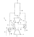
本発明の実施例1に係るガスタービン設備100を、図1を参照して説明する。
図1に示すように、実施例1のガスタービン設備100は、ガスタービン10、排熱回収ボイラー20及び熱交換部110を備えている。
A
As shown in FIG. 1, the
ガスタービン10は、圧縮機11と燃焼器12とタービン13を主要部材として構成されている。圧縮機11は空気Aを圧縮して圧縮空気A1を燃焼器12に送る。燃焼器12では、圧縮機11から圧縮空気A1が送られると共に、燃料ラインL1を通して燃料ガスFが供給され、燃料ガスFを燃焼させて高温・高圧の燃焼ガスBを発生する。この高温・高圧の燃焼ガスBがタービン13で膨張してタービン13が回転駆動し、タービン13の回転力により発電機(図示省略)を回転して発電が行われる。
The
排熱回収ボイラー(HRSG: heat recovery steam generator) 20は、タービン13から排出される高温・高圧の排気ガスEのエネルギーを回収し、回収した熱により高温・高圧の蒸気を発生させ、この蒸気により蒸気タービン(図示省略)を回転させている。
A heat recovery steam generator (HRSG) 20 recovers the energy of the high-temperature and high-pressure exhaust gas E discharged from the
熱交換部110は、循環ライン111に、冷却空気冷却器112と燃料ガス加熱器11
3とポンプ114を接続して構成されている。
The
3 and a
循環ライン111は、熱伝達媒体を循環流通させるライン(配管)であり、熱伝達媒体としては例えば水Wを使用している。なお、熱伝達媒体としては、液体が好ましく、例えば水や油などを採用することができる。
ポンプ114が駆動することにより、熱伝達媒体である水Wは、循環ライン111内を循環流通する。
The
When the
圧縮機11で圧縮された空気の一部は分岐され、この分岐された圧縮空気A2は圧縮空気ラインL4を通ってタービン13に送られてタービン翼の冷却をする。
A part of the air compressed by the
冷却空気冷却器112は、循環ライン111に接続されると共に、圧縮空気ラインL4に接続されており、熱伝達媒体である水Wにより圧縮空気A2を冷却し、冷却した圧縮空気A2によりタービン13のタービン翼の冷却をしている。
この場合、圧縮機11から出ていく圧縮空気A2の温度は例えば400〜450℃であり、冷却空気冷却器112により冷却されてタービン13に送られる圧縮空気A2の温度は例えば200〜250℃になる。
また、冷却空気冷却器112に入る熱伝達媒体である水Wの温度は例えば150℃であり、冷却空気冷却器112から出ていく水Wは昇温してその温度は例えば200〜250℃になる。
The cooling
In this case, the temperature of the compressed air A2 exiting from the
Moreover, the temperature of the water W that is a heat transfer medium entering the cooling
燃料ガス加熱器113は、熱伝達媒体である水Wの流れ方向に関して冷却空気冷却器112よりも下流位置で、循環ライン111に接続されると共に、燃料ラインL1に接続されている。燃料ガス加熱器113は、冷却空気冷却器112から送られてくる昇温した熱伝達媒体である水Wにより燃料ガスFを予熱する。予熱された燃料ガスFは燃焼器12に送られて燃焼する。
この場合、燃料ガス加熱器113に入る熱伝達媒体である水Wの温度は例えば200〜250℃であり、燃料ガス加熱器113から出ていく水Wは降温してその温度は例えば150℃になる。
The
In this case, the temperature of the water W that is the heat transfer medium entering the
燃料ガス加熱器113から出ていく水Wは、ポンプ114により送られて、再び冷却空気冷却器112に送られ、循環流通する。
The water W exiting from the
結局、実施例1のガスタービン設備100では、循環ライン111を循環流通する熱伝達媒体である水Wが、圧縮空気A2と燃料ガスFとの熱交換をして、圧縮空気A2の冷却と燃料ガスFの予熱を同時に実施している。このため熱の有効利用をすることができる。
Eventually, in the
このように、タービン13のタービン翼を冷却する圧縮空気A2を冷却することで、冷却能力が向上するため抽出する空気量を減少させることができ、ガスタービンの出力向上及び効率の改善につながる。
また、圧縮空気A2の冷却に伴う廃熱を用いて、燃料ガスFの予熱を行うことで、廃熱の有効活用ができるため効率を改善できる。
Thus, by cooling the compressed air A2 that cools the turbine blades of the
Moreover, since the waste heat can be effectively utilized by preheating the fuel gas F by using the waste heat accompanying the cooling of the compressed air A2, the efficiency can be improved.
しかも、熱交換部110は、蒸気タービンサイクル側の給水を用いることなく、蒸気夕−ビンサイクル側とは独立したシステムであるため、プラントの起動時や、蒸気タービン側が停止してガスタービン10が単独運転しているときであっても、問題なく、圧縮空気A2の冷却及び燃料ガスFの予熱を行うことができる。
Moreover, the
なお、液体の熱伝達媒体である水W等を使用せずに、燃料ガスFと圧縮空気A2とを熱交換器を用いて直接熱交換することも考えられるが、本実施例では、熱伝達媒体として液体の水W等を用いることで熱交換部での熱伝達を向上させることができ、熱交換器のサイズを小さくすることができる。また、これによりコストダウンを図ることができる。
また、燃料ガスの予熱のため補助ボイラーを設置する必要がないため、コストダウンを図ることができる。
Note that it is possible to directly exchange heat between the fuel gas F and the compressed air A2 using a heat exchanger without using water W or the like which is a liquid heat transfer medium. By using liquid water W or the like as a medium, heat transfer in the heat exchange unit can be improved, and the size of the heat exchanger can be reduced. This can also reduce the cost.
In addition, since it is not necessary to install an auxiliary boiler for preheating the fuel gas, the cost can be reduced.
また、熱伝達媒体として水W等の液体を使用しているため、熱伝達媒体が気体である場合よりも熱交換部110を小型化、さらにはガスタービン設備1全体の小型化を図ることができる。
In addition, since a liquid such as water W is used as the heat transfer medium, the
本発明の実施例2に係るガスタービン設備100Aを、図2を参照して説明する。実施例2のガスタービン設備100Aは、実施例1のガスタービン設備100を改良したものであるため、実施例1と同一部分には同一符号を付し、重複する部分の説明は省略する。
A
図2に示すように、実施例2のガスタービン設備100Aは、ガスタービン10、排熱回収ボイラー20及び熱交換部110を備えている。
As shown in FIG. 2, the
更に実施例2のガスタービン設備100Aでは、圧縮空気ラインL4に、圧縮空気バイパスライン115が設けられている。この圧縮空気バイパスライン115は、圧縮空気ラインL4のうちで、圧縮空気A2の流れ方向に関して冷却空気冷却器112よりも上流側部分と冷却空気冷却器112よりも下流側部分を接続するものであり、流量制御弁V1が介装されている。
Furthermore, in the
また、圧縮空気ラインL4のうち、圧縮空気バイパスライン115の上流側か接続されている部分と冷却空気冷却器112が接続されている部分の間には、流量制御弁V2が介装されている。なお、流量制御弁V2を、圧縮空気ラインL4のうち、圧縮空気バイパスライン115の下流側が接続されている部分と冷却空気冷却器112が接続されている部分の間に介装してもよい。
Further, in the compressed air line L4, a flow control valve V2 is interposed between a portion connected to the upstream side of the compressed
燃料ラインL1には、燃料バイパスライン116が設けられている。この燃料バイパスライン116は、燃料ラインL1のうちで、燃料ガスFの流れ方向に関して燃料ガス加熱器113よりも上流側部分と燃料ガス加熱器113よりも下流側部分を接続するものであり、流量制御弁V3が介装されている。
A
また燃料ラインL1のうち、燃料バイパスライン116の上流側か接続されている部分と燃料ガス加熱器113が接続されている部分の間には、流量制御弁V4が介装されている。なお、流量制御弁V4を、燃料ラインL1のうち、燃料バイパスライン116の下流側が接続されている部分と燃料ガス加熱器113が接続されている部分の間に介装してもよい。
In addition, a flow control valve V4 is interposed between a portion of the fuel line L1 connected to the upstream side of the
他の部分の構成は、図1に示す実施例1と同様である。 The configuration of the other parts is the same as that of the first embodiment shown in FIG.
実施例2に係るガスタービン設備100Aでは、部分負荷や負荷変動が発生した場合において、流量制御弁V1,V2の開度を調整することにより、圧縮空気バイパスライン115を流れる圧縮空気A2の流量と冷却空気冷却器112を流れる圧縮空気A2の流量を調整することにより、タービン13に送られていく圧縮空気A2の温度を容易に調整することができる。
また、流量制御弁V3,V4の関度を調整することにより、燃料バイパスライン116を流れる燃料ガスFの流量と燃料ガス加熱器113を流れる燃料ガスFの流量を調整することにより、燃焼器12に送られていく燃料ガスFの温度を容易に調整することができる。
In the
Further, by adjusting the relationship between the flow rate control valves V3 and V4, the flow rate of the fuel gas F flowing through the
このように、圧縮空気バイパスライン115,116及び流量制御弁V1,V2,V3,V4を用いて温度調整をすることができるため、部分負荷や負荷変動が発生した場合であっても、圧縮空気A2の冷却及び燃料ガスFの予熱を過不足なく実施することができ、効率を向上させることができる。
Thus, since the temperature can be adjusted using the compressed
なお、図2に示す実施例2において、圧縮空気バイパスライン115及び流量制御弁V1,V2からなる圧縮空気の温度調整手段と、燃料バイパスライン116及び流量制御弁V3,V4からなる燃料ガスの温度調整手段のうち、一方のみを備えるようにすることもできる。
In the second embodiment shown in FIG. 2, the temperature of the compressed air comprising the compressed
本発明の実施例3に係るガスタービン設備100Bを、図3を参照して説明する。実施例3のガスタービン設備100Bは、圧縮空気の温度調整手段と燃料ガスの温度調整手段が、実施例2のガスタービン設備100Aのものと異なるが、他の部分は実施例2と同様である。したがって実施例2と異なる部分についてのみ説明をする。
A
循環ライン111には、第1の熱伝達媒体バイパスライン117が設けられている。この熱伝達媒体バイパスライン117は、循環ライン111のうちで、水(熱伝達媒体)Wの流れ方向に関して冷却空気冷却器112よりも上前側部分と冷却空気冷却器112よりも下流側部分を接続するものであり、流量制御弁V5が介装されている。
The
また循環ライン111のうち、熱伝達媒体バイパスライン117の上流側か接続されている部分と冷却空気冷却器112が接続されている部分の間には、流量制御弁V6が介装されている。なお、流量制御弁V6を、循環ライン111のうち、熱伝達媒体バイパスライン117の下流側が接続されている部分と冷却空気冷却器112が接続されている部分の間に介装してもよい。
Further, in the
循環ライン111には、第2の熱伝達媒体バイパスライン118が設けられている。この熱伝達媒体バイパスライン118は、循環ライン111のうちで、水(熱伝達媒体)Wの流れ方向に関して燃料ガス加熱器113よりも上前側部分と燃料ガス加熱器113よりも下流側部分を接続するものであり、流量制御弁V7が介装されている。
The
また循環ライン111のうち、熱伝達媒体バイパスライン118の上流側か接続されている部分と燃料ガス加熱器113が接続されている部分の間には、流量制御弁V8が介装されている。なお、流量制御弁V8を、循環ライン111のうち、熱伝達媒体バイパスライン118の下流側が接続されている部分と燃料ガス加熱器113が接続されている部分の間に介装してもよい。
In addition, a flow control valve V8 is interposed between a portion of the
実施例3に係るガスタービン設備100Bでは、部分負荷や負荷変動が発生した場合において、流量制御弁V5,V6の関度を調整することにより、熱伝達媒体バイパスライン117を流れる水Wの流量と冷却空気冷却器112を流れる水Wの流量を調整することにより、タービン13に送られていく圧縮空気A2の温度を容易に調整することができる。
また、流量制御弁V7,V8の開度を調整することにより、熱伝達媒体バイパスライン118を流れる水Wの流量と燃料ガス加熱器113を流れる水Wの流量を調整することにより、燃焼器12に送られていく燃料ガスFの温度を容易に調整することができる。
In the
Further, the
このように、熱伝達媒体バイパスライン117,118及び流量制御弁V5,V6,V7,V8を用いて温度調整をすることができるため、部分負荷や負荷変動が発生した場合であっても、圧縮空気A2の冷却及び燃料ガスFの予熱を過不足なく実施することができ、効率を向上させることができる。
As described above, since the temperature can be adjusted using the heat transfer
なお、図3に示す実施例3において、熱伝達媒体バイパスライン117及び流量制御弁V5、V6からなる圧縮空気の温度調整手段と、熱伝達媒体バイパスライン118及び流量制御弁V7、V8からなる燃料ガスの温度調整手段のうち、一方のみを備えるようにすることもできる。
In the third embodiment shown in FIG. 3, the temperature adjusting means for compressed air including the heat transfer
また、図3に示す実施例3において、熱伝達媒体バイパスライン117及び流量制御弁V5,V6からなる圧縮空気の温度調整手段の代わりに、図2に示す実施例2において説明される、圧縮空気バイパスライン115及び流量制御弁V1,V2からなる圧縮空気の温度調整手段を備えるようにすることもできる。
Further, in the third embodiment shown in FIG. 3, instead of the compressed air temperature adjusting means including the heat transfer
更に、図3に示す実施例3において、熱伝達媒体バイパスライン118及び流量制御弁V7,V8からなる燃料ガスの温度調整手段の代わりに、図2に示す実施例2において説明される、燃料バイパスライン116及び流量制御弁V3,V4からなる燃料ガスの温度調整手段を備えるようにすることもできる。
Further, in the third embodiment shown in FIG. 3, the fuel bypass described in the second embodiment shown in FIG. 2 is used instead of the fuel gas temperature adjusting means including the heat transfer
本発明の実施例4に係るガスタービン設備100Cを、図4を参照して説明する。実施例4のガスタービン設備100Cは、実施例1、実施例2、または実施例3のガスタービン設備100、100A、または100Bを改良したものである。以下では実施例1のガスタービン設備100を改良した形態で説明するため、実施例1と同一部分には同一符号を付し、重複する部分の説明は省略する。
A
更に実施例4のガスタービン設備100Cでは、循環ライン111のうち燃料ガス加熱器113よりも下流側に、給水加熱器120が接続されている。この給水加熱器120は、蒸気タービンサイクル側の給水である水W3を排熱回収ボイラー20に送る給水ラインL5にも接続されており、熱伝達媒体である水Wにより、蒸気タービンサイクル側の給水である水W3の加熱をしている。
例えば、水W3の温度は、給水加熱器120に入るときは50〜100℃であり、給水加熱器120から出るときには100〜150℃になる。
これにより、圧縮空気A2の廃熱により、燃料ガスFだけでなく、蒸気タービンサイクル側の給水である水W3の加熱も同時に行うことができる。
Furthermore, in the
For example, the temperature of the water W 3 is 50 to 100 ° C. when entering the
Thereby, not only the fuel gas F but also the water W3, which is the feed water on the steam turbine cycle side, can be simultaneously heated by the waste heat of the compressed air A2.
なお、燃焼器12が最も高温となるため、より高温の流体が燃焼器12に流れ込むように、燃料ガスFを加熱する燃料ガス加熱器113は、循環ライン111のうちで、水(熱伝達媒体)Wの流れ方向に関して給水加熱器120よりも上流側に接続することが好ましいが、循環ライン111のうち燃料ガス加熱器113よりも上流側に、給水加熱器120を接続することもできる。
In addition, since the
本発明の実施例5に係るガスタービン設備200を、図5を参照して説明する。
図5に示すように、実施例5のガスタービン設備200は、ガスタービン10、排熱回収ボイラー20及びヒートパイプ熱交換部210を備えている。
A
As shown in FIG. 5, the
ガスタービン10は、圧縮機11と燃焼器12とタービン13を主要部材として構成されている。圧縮機11は空気Aを圧縮して圧縮空気A1を燃焼器12に送る。燃焼器12では、圧縮機11から圧縮空気A1が送られると共に、燃料ラインL1を通して燃料ガスFが供給され、燃料ガスFを燃焼させて高温・高圧の燃焼ガスBを発生する。この高温・高圧の燃焼ガスBがタービン13で膨張してタービン13が回転駆動し、タービン13の回転力により発電機(図示省略)を回転して発電が行われる。
The
圧縮機11で圧縮された空気の一部は分岐され、この分岐された圧縮空気A2は圧縮空気ラインL4を通ってタービン13に送られてタービン翼の冷却をする。
A part of the air compressed by the
排熱回収ボイラー(HRSG: heat recovery steam generator) 20は、タービン13から排出される高温・高圧の排気ガスEのエネルギーを回収し、回収した熱により高温・高圧の蒸気を発生させ、この蒸気により蒸気タービン(図示省略)を回転させている。
A heat recovery steam generator (HRSG) 20 recovers the energy of the high-temperature and high-pressure exhaust gas E discharged from the
ヒートパイプ熱交換部210は、圧縮空気ラインL4と燃料ラインL1に接続されており、熱伝達媒体であるヒートパイプ211を用いて、圧縮空気ラインL4を流れる圧縮空気A2から熱を奪い、燃料ラインL1を流れる燃料ガスFに熱を与える。つまり、ヒートパイプ211を介して、圧縮空気A2の熱を燃料ガスFに熱伝達し、圧縮空気A2の冷却と燃料ガスFの予熱を同時に実施している。このため熱の有効利用をすることができる。
The heat pipe
ここで正面側から見た断面図である図6を参照して、ヒートパイプ熱交換部210の構造について説明する。
図6に示すように、ヒートパイプ熱交換部210は、筐体212内に水平な隔壁213が備えられており、この隔壁213により筐体212内は上側空間214aと下側空間214bに分離・区画されている。
複数本のヒートパイプ211は鉛直方向に沿い配置されて、隔壁213を貫通する状態で設置されており、ヒートパイプ211の上側部分は上側空間214aに露出し、ヒートパイプ211の下側部分は下側空間214bに露出している。
ヒートパイプ211の上側部分及び下側部分には、フィン211aが取り付けられている。
Here, the structure of the heat pipe
As shown in FIG. 6, the heat pipe
The plurality of
上側空間214aには燃料ラインL1が接続されており、燃料ラインL1を流れる燃料ガスFが上側空間214a内を流通する。また、下側空間214bには圧縮空気ラインL4が接続されており、圧縮空気ラインL4を流れる圧縮空気A2が下側空間214b内を流通する。
このため、高温側の圧縮空気A2の熱を、低温側の燃料ガスFに熱伝達することができる。この場合、ヒートパイプ211を鉛直配置し、下方側を高温域とし上方側を低温域としているため、ヒートパイプ211の熱伝達性能が高くなる。
A fuel line L1 is connected to the
For this reason, the heat of the compressed air A2 on the high temperature side can be transferred to the fuel gas F on the low temperature side. In this case, since the
このため、圧縮空気A2は抜熱されて冷却され、タービン13のタービン翼の冷却を効果的に行うことができる。この結果、冷却能力が向上するため抽出する空気量を減少させることができ、ガスタービンの出力向上及び効率の改善につながる。
For this reason, the compressed air A2 is extracted and cooled, and the turbine blades of the
また、圧縮空気A2の冷却に伴う廃熱を用いて、燃料ガスFの予熱を行うことで、廃熱の有効活用ができるため効率を改善できる。 Moreover, since the waste heat can be effectively utilized by preheating the fuel gas F by using the waste heat accompanying the cooling of the compressed air A2, the efficiency can be improved.
ヒートパイプ熱交換部210は、蒸気タービンサイクル側の給水を用いることなく、蒸気タービンサイクル側とは独立したシステムであるため、プラントの起動時や、蒸気タービン側が停止してガスタービン10が単独運転しているときであっても、問題なく、圧縮空気A2の冷却及び燃料ガスFの予熱を行うことができる。
The heat pipe
また、ヒートパイプ211を用いるため、熱交換のために特に動力は必要としない。更に、ヒートパイプ211を介して熱交換を行うため、例えば高温側(圧縮空気A2)の熱伝達に使用可能な表面積は、低温側(燃料ガスF)に制限されることなく設定することができる。
ヒートパイプ211の形状はほぼ円筒形であるが、ヒートパイプの代わりに、平坦プレートを含む様々な形状及び寸法の導管を採用することもできる。
Further, since the
The shape of the
本実施例のガスタービン設備200では、ヒートパイプ211により熱伝達をする構成にしたので、装置が単純になると共に、特に動力を要しないためコストダウンを図ることができる。
また、圧縮空気A2と燃料ガスFとを熱交換器(ガスーガス熱交換器)を用いて直接熱交換させる場合に比べて、ヒートパイプ211を介することで熱伝達を向上させることができるため、熱交換部210のサイズを小さくすることができる。また、これによりコストダウンを図ることができる。
In the
In addition, heat transfer can be improved through the
本発明の実施例6に係るガスタービン設備200Aを、図7を参照して説明する。実施例6のガスタービン設備200Aは、実施例5のガスタービン設備200を改良したものであるため、実施例5と同一部分には同一符号を付し、重複する部分の説明は省略する。
A
図7に示すように、実施例6のガスタービン設備200Aは、ガスタービン10、排熱回収ボイラー20及びヒートパイプ熱交換部210を備えている。
As shown in FIG. 7, the
更に実施例6のガスタービン設備200Aでは、圧縮空気ラインL4に、圧縮空気バイパスライン215が設けられている。この圧縮空気バイパスライン215は、圧縮空気ラインL4のうちで、圧縮空気A2の流れ方向に関してヒートパイプ熱交換器210よりも上流側部分とヒートパイプ熱交換器210よりも下流側部分を接続するものであり、流量制御弁V11が介装されている。
Furthermore, in the
また、圧縮空気ラインL4のうち、圧縮空気バイパスライン215の上流側か接続されている部分とヒートパイプ熱交換器210が接続されている部分の間には、流量制御弁V12が介装されている。なお、流量制御弁V12を、圧縮空気ラインL4のうち、圧縮空気バイパスライン215の下流側が接続されている部分とヒートパイプ熱交換器210が接続されている部分の間に介装してもよい。
Further, in the compressed air line L4, a flow control valve V12 is interposed between a portion connected to the upstream side of the compressed
燃料ラインL1には、燃料バイパスライン216が設けられている。この燃料バイパスライン216は、燃料ラインL1のうちで、燃料ガスFの流れ方向に関してヒートパイプ熱交換部210よりも上前側部分とヒートパイプ熱交換部210よりも下流側部分を接続するものであり、流量制御弁V13が介装されている。
A
また燃料ラインL1のうち、燃料バイパスライン216の上流側か接続されている部分とヒートパイプ熱交換器210が接続されている部分の間には、流量制御弁V14が介装されている。なお、流量制御弁V14を、燃料ラインL1のうち、燃料バイパスライン216の下流側が接続されている部分とヒートパイプ熱交換器210が接続されている部分の間に介装してもよい。
Further, in the fuel line L1, a flow control valve V14 is interposed between a portion connected to the upstream side of the
他の部分の構成は、図5に示す実施例5と同様である。 The configuration of other parts is the same as that of the fifth embodiment shown in FIG.
実施例6に係るガスタービン設備200Aでは、部分負荷や負荷変動が発生した場合において、流量制御弁V11、V12の開度を調整することにより、圧縮空気バイパスライン215を流れる圧縮空気A2の流量とヒートパイプ熱交換器210を流れる圧縮空気A2の流量を調整することにより、タービン13に送られていく圧縮空気A2の温度を容易に調整することができる。
また、流量制御弁V13、V14の開度を調整することにより、燃料バイパスライン216を流れる燃料ガスFの流量とヒートパイプ熱交換器210を流れる燃料ガスFの流量を調整することにより、燃焼器12に送られていく燃料ガスFの温度を容易に調整することができる。
In the
Further, by adjusting the opening degree of the flow control valves V13 and V14, the combustor is adjusted by adjusting the flow rate of the fuel gas F flowing through the
このように、バイパスライン215,216及び流量制御弁V11,V12,V13,V14を用いた温度調整をすることができるため、部分負荷や負荷変動が発生した場合であっても、圧縮空気A2の冷却及び燃料ガスFの予熱を過不足なく実施することができ、効率を向上させることができる。
As described above, since the temperature adjustment using the
なお、図7に示す実施例6において、圧縮空気バイパスライン215及び流量制御弁V11,V12からなる圧縮空気の温度調整手段と、燃料バイパスライン216及び流量制御弁V13,V14からなる燃料ガスの温度調整手段のうち、一方のみを備えるようにすることもできる。
In the sixth embodiment shown in FIG. 7, the temperature adjusting means for compressed air including the compressed
本発明の実施例7に係るガスタービン設備100について説明する。実施例7のガスタービン設備100は、実施例1のガスタービン設備100を改良したものであるため、実施例1と同一部分には同一符号を付し、重複する部分の説明は省略する。
A
実施例7のガスタービン設備は、熱伝達媒体として、圧縮機11から導出される圧縮空気A1及び燃料ガスFと混合されて不燃状態を維持可能な物質を使用している。すなわち、熱伝達媒体は、約350〜500℃の圧縮空気A1と混合しても発火しない程度の不燃性を有し、且つ燃料ガスFと混合して発火する助燃性を有さない物質である。
The gas turbine equipment of the seventh embodiment uses a substance that can be mixed with the compressed air A1 and the fuel gas F derived from the
上記の熱伝達媒体として、例えば実施形態1の水の他、ヘリウム、二酸化炭素や窒素等の気体、塩化亜鉛、亜硝酸ナトリウム、硝酸ナトリウム若しくは硝酸カリウム又はこれらの混合物等の溶融塩、はんだ、スズ等の液体金属が挙げられる。さらには、ジベンジルトルエンを主成分とする油(商品名:「バーレムサーム400」松村石油株式会社)等の合成系有機熱媒体油が挙げられる。
As the heat transfer medium, for example, in addition to the water of Embodiment 1, helium, carbon dioxide, nitrogen and other gases, zinc chloride, sodium nitrite, sodium nitrate, potassium nitrate or a mixture thereof, solder, tin, etc. Liquid metals. Furthermore, synthetic organic heat transfer medium oils such as an oil mainly composed of dibenzyltoluene (trade name: “
実施例7に係るガスタービン設備100では、例えば燃料ガス加熱器113を構成する伝熱管に損傷が生じた場合に、伝熱管内から漏出した熱伝達媒体が圧縮空気A1又は燃料ガスFと混合したとしても発火する虞がない。よって、ガスタービン設備100の安全性を確保することができる。
In the
本発明の実施例8に係るガスタービン設備100について説明する。実施例8のガスタービン設備100は、実施例1のガスタービン設備100を改良したものであるため、実施例1と同一部分には同一符号を付し、重複する部分の説明は省略する。
A
実施例8のガスタービン設備は、ポンプ114が駆動していない状態においても、熱伝達媒体が大気圧よりも大きい圧力で加圧されており、これにより熱伝達媒体の静圧が増加されている。例えば、前準備として大気圧よりも大きい圧力で加圧された熱伝達媒体を準備しておき、加圧されたこの熱伝達媒体を循環ライン111に導入する。
In the gas turbine facility of the eighth embodiment, even when the
実施例8に係るガスタービン設備100では、熱伝達媒体が液体の場合には飽和温度(沸点)が上昇し、高い温度まで液体の状態を保つことができる。また、熱伝達媒体が気体の場合には密度が高くなるため、効率的に熱交換することができる。よって、燃料ガス加熱器113及び冷却空気冷却器112の小型化、さらにはガスタービン設備1全体の小型化を図ることができる。
In the
本発明の実施例9に係るガスタービン設備100について説明する。実施例9のガスタービン設備100は、実施例1のガスタービン設備100を改良したものであるため、実施例1と同一部分には同一符号を付し、重複する部分の説明は省略する。
A
実施例9のガスタービン設備は、熱伝達媒体として、飽和温度よりも5度以上低い温度の亜臨界圧流体、擬臨界温度よりも5度以上低い温度の超臨界圧流体、又は臨界温度よりも5度以上低い温度の臨界圧流体を使用している。なお、擬臨界温度とは超臨界圧流体において、定圧比熱が極大となる温度のことである。 The gas turbine equipment of Example 9 is used as a heat transfer medium, a subcritical pressure fluid having a temperature lower than the saturation temperature by 5 degrees or more, a supercritical pressure fluid having a temperature lower than the pseudocritical temperature by 5 degrees or more, or a critical temperature. A critical pressure fluid with a temperature lower than 5 degrees is used. The pseudocritical temperature is a temperature at which the constant pressure specific heat becomes maximum in the supercritical fluid.
ここで、本実施例で用いる熱伝達媒体の一例として水の温度と定圧比熱の関係を図8に示す。図8では、横軸が温度を、縦軸が定圧比熱をそれぞれ示している。図8によれば、亜臨界圧21.0MPaの水は飽和温度P21.0よりも5度以上低い場合、臨界圧22.12MPaの水は臨界温度P22.12よりも5度以上低い場合、超臨界圧23.0MPaの水は擬臨界温度P23.0よりも5度以上低い場合、超臨界圧24.0MPaの水は擬臨界温度P24.0よりも5度以上低い場合にはそれぞれ定圧比熱が低いことが示されている。 Here, as an example of the heat transfer medium used in the present embodiment, the relationship between the water temperature and the constant pressure specific heat is shown in FIG. In FIG. 8, the horizontal axis represents temperature, and the vertical axis represents constant pressure specific heat. According to FIG. 8, when the water having a subcritical pressure of 21.0 MPa is 5 degrees or more lower than the saturation temperature P 21.0 , the water having a critical pressure of 22.12 MPa is lower than 5 degrees lower than the critical temperature P 22.12. When water with a supercritical pressure of 23.0 MPa is 5 degrees or more lower than the pseudocritical temperature P 23.0 , water with a supercritical pressure of 24.0 MPa is lower than 5 degrees lower than the pseudocritical temperature P 24.0 It is shown that the specific pressure specific heat is low.
このように、実施例9に係るガスタービン設備100では、熱伝達媒体の定圧比熱が高い温度領域を避けて使用し、熱伝達媒体を効率的に高温にすることができるため、燃料ガス加熱器113における熱交換及び燃料ガスFの予熱を効率的に行うことができる。
Thus, in the
本発明の実施例10に係るガスタービン設備100Dを、図9を参照して説明する。実施例10のガスタービン設備100Dは、実施例1のガスタービン設備100を改良したものであるため、実施例1と同一部分には同一符号を付し、重複する部分の説明は省略する。
A
図9に示すように、実施例10のガスタービン設備100Dは、ガスタービン10、排熱回収ボイラー20及び熱交換部110を備えている。
As shown in FIG. 9, the
更に実施例10のガスタービン設備100Dでは、排熱回収ボイラー20で生成した高温の温水Hを流通させる第一流通ラインM1と、燃料ガスFを流通させる第一燃料ガスラインF1と、第一流通ラインM1に接続された燃料ガス用熱交換器131とを有している。
Furthermore, in the
第一流通ラインM1は、排熱回収ボイラー20と燃料ガス用熱交換器131とを接続しており、排熱回収ボイラー20から導出された温水Hを排熱回収ボイラー20と燃料ガス用熱交換器131との間で循環させている。
The first distribution line M1 connects the exhaust
燃料ガス用熱交換器131は、第一流通ラインM1に接続されると共に、第一燃料ガスラインF1に接続されている。燃料ガス用熱交換器131は、排熱回収ボイラー20から送られてくる温水Hにより燃料ガスFを予熱する。予熱された燃料ガスFは燃料ガス加熱器113に送られてさらに高い温度に予熱される。
The fuel
また、冷却空気冷却器112とタービン13とを接続する圧縮空気ラインL4には、冷却空気冷却器112から導出される圧縮空気A2の流量を調整する流量調整弁134と、圧縮空気ラインL4を流通する圧縮空気A2の温度を測定する温度測定部135とが設けられている。
The compressed air line L4 that connects the cooling
他の部分の構成は、図1に示す実施例1と同様である。 The configuration of the other parts is the same as that of the first embodiment shown in FIG.
実施例10に係るガスタービン設備100Dでは、排熱回収ボイラー20で生成される温水Hを利用して燃料ガス用熱交換器131にて燃料ガスFを予熱した後、冷却空気冷却器112から送り出される温水Hよりも高温の水Wを利用して燃料ガス加熱器113にて燃料ガスFをさらに高温に予熱することができる。よって、廃熱を用いて燃料ガスFを効率的に予熱することができるため、熱の有効利用を図ることができるとともに、ガスタービン設備100D全体のエネルギー効率を高めることができる。
In the
また、例えば排熱回収ボイラー20が停止している場合でも、実施例1と同様に、燃料ガス加熱器113において燃料ガスFを予熱することができるとともに、燃料ガス加熱器113で熱交換した水Wを用いて冷却空気冷却器112において圧縮空気A2を冷却することができる。
For example, even when the exhaust
また、圧縮空気ラインL4を流通する圧縮空気A2の温度を温度測定部135により測定して、測定結果に応じて流量調整弁134の開度を調整して、タービン13に導入される圧縮空気A2の温度を一定に維持することができる。よって、一定条件下でタービン13を稼動することができるため、ガスタービン設備100Dとしての信頼性を高めることができる。
Further, the temperature of the compressed air A2 flowing through the compressed air line L4 is measured by the
本発明の実施例11に係るガスタービン設備100Eを、図10を参照して説明する。実施例11のガスタービン設備100Eは、実施例10のガスタービン設備100Dを改良したものであるため、実施例10と同一部分には同一符号を付し、重複する部分の説明は省略する。
A
図10に示すように、実施例11のガスタービン設備100Eは、ガスタービン10、排熱回収ボイラー20、熱交換部110、第一流通ラインM1、第一燃料ガスラインF1及び燃料ガス用熱交換器131を備えている。
As shown in FIG. 10, the
更に実施例11のガスタービン設備100Eでは、排熱回収ボイラー20で生成した高温の温水Hを流通させる第二流通ラインM2と、第二流通ラインM2に接続された燃料ガス用熱交換器132と、燃料ガスFを流通させる第二燃料ガスラインF2と、排熱回収ボイラー20から導出された水Iを流通させる第三流通ラインM3と、第三流通ラインM3に接続された圧縮空気用熱交換器136とを有している。
Furthermore, in the
第二流通ラインM2は、排熱回収ボイラー20と燃料ガス用熱交換器132とを接続しており、排熱回収ボイラー20から導出された温水Hを排熱回収ボイラー20と燃料ガス用熱交換器132との間で循環させている。
The second distribution line M2 connects the exhaust
燃料ガス用熱交換器132は、第二流通ラインM2に接続されると共に、第二燃料ガスラインF2に接続されている。燃料ガス用熱交換器132は、排熱回収ボイラー20から送り出される温水Hにより燃料ガスFを予熱する。予熱された燃料ガスFは燃料ガス加熱器113に送られてさらに高い温度に予熱される。
つまり、実施例11では、複数の燃料ガス用熱交換器131,132を有している。
The fuel
That is, in Example 11, the fuel
第三流通ラインM3は、排熱回収ボイラー20と圧縮空気用熱交換器136とを接続しており、排熱回収ボイラー20から導出された水Iを排熱回収ボイラー20と圧縮空気用熱交換器136との間で循環させている。
The third distribution line M3 connects the exhaust
圧縮空気用熱交換器136は、第三流通ラインM3に接続されると共に、圧縮空気ラインL6に接続されている。圧縮空気用熱交換器136は、排熱回収ボイラー20から送られてくる水Iと冷却空気冷却器112から送られてくる圧縮空気A2とを熱交換する。これにより、圧縮空気A2の温度が下がり、水Iの温度が上昇する。
The compressed
他の部分の構成は、図9に示す実施例10と同様である。
The structure of other parts is the same as that of the
実施例11に係るガスタービン設備100Eでは、複数の燃料ガス用熱交換器131,132を設けることにより燃料ガスFを効率的に予熱することができるため、熱の有効利用を図ることができるとともに、ガスタービン設備100E全体のエネルギー効率を高めることができる。
In the
また、圧縮空気用熱交換器136において、排熱回収ボイラー20から送り出される水Iを利用して、圧縮空気A2をさらに冷却することができるので、圧縮空気A2による冷却の対象となる部材を効果的に冷却し、過熱による損傷を防止することができる。更に、その廃熱を水Iに有効に回収し、エネルギー効率を更に高めることができる。
Moreover, in the
本発明の実施例12に係るガスタービン設備100Fを、図11を参照して説明する。実施例12のガスタービン設備100Fは、実施例10のガスタービン設備100Dを改良したものであるため、実施例10と同一部分には同一符号を付し、重複する部分の説明は省略する。
A
図11に示すように、実施例12のガスタービン設備100Fは、第一流通ラインM1と、第一燃料ガスラインF1と、燃料ガス用熱交換器131とを有している。
As shown in FIG. 11, the
更に実施例12のガスタービン設備100Fでは、タービン13と排熱回収ボイラー20との間に第一ダンパーD1を介してバイパススタック137が設けられている。
Further, in the
タービン13と排熱回収ボイラー20とは第一排気ガスラインH1で接続されており、該第一排気ガスラインH1には第二ダンパーD2が設けられている。また、第一排気ガスラインH1から分岐して第二排気ガスラインH2が設けられ、該第二排気ガスラインH2に第一ダンパーD1とバイパススタック137とが設けられている。このバイパススタック137は、タービン13から排出された排気ガスEを大気に放出する。
The
他の部分の構成は、図9に示す実施例10と同様である。
The structure of other parts is the same as that of the
実施例12に係るガスタービン設備100Fでは、第一ダンパーD1を開状態にするとともに第二ダンパーD2を閉状態とすることで、排気ガスEをバイパススタック137に送って、該バイパススタック137から排気ガスEを大気に放出することができる。よって、排熱回収ボイラー20の空焚きを防止することができるため、該排熱回収ボイラー20が簡易な構成であっても該排熱回収ボイラー20の損傷を防止することができる。
In the
一方、第一ダンパーD1を閉状態にするとともに第二ダンパーD2を開状態とすることで、排気ガスEを排熱回収ボイラー20に送って、実施例10と同様に、排熱回収ボイラー20で生成される温水Hを利用して燃料ガス用熱交換器131にて燃料ガスFを予熱した後、冷却空気冷却器112から送り出される温水Hよりも高温の水Wを利用して燃料ガス加熱器113にて燃料ガスFをさらに予熱することができる。
On the other hand, exhaust gas E is sent to the exhaust
以上のように、第一ダンパーD1及び第二ダンパーD2の開閉状態を調整することで、ガスタービン設備100Fの使用態様を変更することができる。例えば、第一ダンパーD1を開状態にするとともに第二ダンパーD2を閉状態とすることで、ガスタービン13を駆動させながら、排熱回収ボイラー20の点検が可能となる。
As described above, the usage mode of the
なお、上述した実施の形態において示した各構成部材の諸形状や組み合わせ等は一例であって、本発明の主旨から逸脱しない範囲において設計要求等に基づき種々変更可能である。 The various shapes and combinations of the constituent members shown in the above-described embodiments are merely examples, and various modifications can be made based on design requirements and the like without departing from the gist of the present invention.
例えば、実施例11において、燃料ガス用熱交換器131,132は並列に設けられているが、直列に設けてもよい。この場合には上流側に配される燃料ガス用熱交換器に導入される温水Hの温度よりも、下流側に配される燃料ガス用熱交換器に導入される温水Hの温度の方を高くすることで、燃料ガスFを段階的に予熱することができる。
For example, in Example 11, the fuel
1 ガスタービン設備
10 ガスタービン
11 圧縮機
12 燃焼器
13 タービン
15 冷却空気冷却器
16 燃料ガス加熱器
20 排熱回収ボイラー
100,100A,100B,100C,100D,100E,100F,200A ガスタービン設備
110 熱交換部
111 循環ライン
112 冷却空気冷却器
113 燃料ガス加熱器
114 ポンプ
115 圧縮空気バイパスライン
116 燃料バイパスライン
117,118 熱伝達媒体バイパスライン
120 給水加熱器
210 ヒートパイプ熱交換部
211 ヒートパイプ
212 筐体
213 隔壁
21a 上側空間
21b 下側空間
215 空気バイパスライン
216 燃料バイパスライン
V1〜V8,V11〜V14 流量制御弁
W,W1,W2、W3 水
L1 燃料ライン
L2,L 3, L 5 給水ライン
L4 圧縮空気ライン
A 空気
A1,A2 圧縮空気
F 燃料ガス
B 燃焼ガス
E 排気ガス
DESCRIPTION OF SYMBOLS 1
Claims (22)
前記タービン翼冷却用の圧縮空気から熱を奪ってこの圧縮空気の冷却をし、奪った熱を熱伝達媒体を介して伝達し、伝達した熱を前記燃料ガスに与えてこの燃料ガスを予熱する熱交換部を備えることを特徴とするガスタービン設備。 A compressor, a combustor that is supplied with compressed air from the compressor, and is supplied with fuel gas through a fuel line to generate combustion gas; and is driven to rotate by the combustion gas, and a part of the compressed air is branched And a turbine for cooling the turbine blades, in which compressed air for cooling the turbine blades is sent through the compressed air line.
Heat is taken from the compressed air for cooling the turbine blades to cool the compressed air, the taken heat is transmitted through a heat transfer medium, and the transferred heat is supplied to the fuel gas to preheat the fuel gas. A gas turbine facility comprising a heat exchange unit.
前記熱交換部は、
液体の熱伝達媒体を循環流通させる循環ラインと、
前記循環ライン及び前記圧縮空気ラインに接続されており、前記熱伝達媒体により前記タービン翼冷却用の圧縮空気を冷却する冷却空気冷却器と、
前記循環ライン及び前記燃料ラインに接続されており、前記熱伝達媒体により前記燃料ガスを予熱する燃料ガス加熱器とを有し、
前記液体の熱伝達媒体を前記循環ライン内で循環流通させることを特徴とするガスタービン設備。 In claim 1,
The heat exchange part is
A circulation line for circulating and circulating a liquid heat transfer medium;
A cooling air cooler that is connected to the circulation line and the compressed air line and cools the compressed air for cooling the turbine blades by the heat transfer medium;
A fuel gas heater connected to the circulation line and the fuel line and preheating the fuel gas by the heat transfer medium;
A gas turbine facility characterized in that the liquid heat transfer medium is circulated in the circulation line.
前記熱伝達媒体は、前記圧縮機から導出される前記圧縮空気及び前記燃料ガスと混合されて不燃状態を維持可能であることを特徴とするガスタービン設備。 In claim 2,
The gas transfer system according to claim 1, wherein the heat transfer medium is mixed with the compressed air and the fuel gas derived from the compressor and can maintain an incombustible state.
前記熱伝達媒体は、大気圧よりも大きい圧力で加圧されていることを特徴とするガスタービン設備。 In claim 2 or claim 3,
The gas turbine equipment, wherein the heat transfer medium is pressurized at a pressure greater than atmospheric pressure.
前記熱伝達媒体は、水または合成系有機熱媒体油のいずれかであることを特徴とするガスタービン設備。 In any one of Claims 2-4,
The gas turbine equipment, wherein the heat transfer medium is either water or a synthetic organic heat medium oil.
前記熱伝達媒体は、飽和温度よりも5度以上低い温度の亜臨界圧流体であること特徴とするガスタービン設備。 In claim 2 or claim 3,
The gas turbine equipment, wherein the heat transfer medium is a subcritical pressure fluid having a temperature 5 degrees or more lower than a saturation temperature.
前記熱伝達媒体は、擬臨界温度よりも5度以上低い温度の超臨界圧流体であることを特徴とするガスタービン設備。 In claim 2 or claim 3,
The gas turbine equipment, wherein the heat transfer medium is a supercritical pressure fluid having a temperature 5 degrees or more lower than the pseudocritical temperature.
前記熱伝達媒体は、臨界温度よりも5度以上低い温度の臨界圧流体であることを特徴とするガスタービン設備。 In claim 2 or claim 3,
The gas turbine equipment, wherein the heat transfer medium is a critical pressure fluid having a temperature 5 degrees or more lower than the critical temperature.
前記熱交換部は、
気体の熱伝達媒体を循環流通させる循環ラインと、
前記循環ライン及び前記圧縮空気ラインに接続されており、前記熱伝達媒体により前記タービン翼冷却用の圧縮空気を冷却する冷却空気冷却器と、
前記循環ライン及び前記燃料ラインに接続されており、前記熱伝達媒体により前記燃料ガスを予熱する燃料ガス加熱器とを有し、
前記気体の熱伝達媒体を前記循環ライン内で循環流通させることを特徴とするガスタービン設備。 In claim 1,
The heat exchange part is
A circulation line for circulating a gas heat transfer medium;
A cooling air cooler that is connected to the circulation line and the compressed air line and cools the compressed air for cooling the turbine blades by the heat transfer medium;
A fuel gas heater connected to the circulation line and the fuel line and preheating the fuel gas by the heat transfer medium;
A gas turbine facility characterized by circulating the gaseous heat transfer medium in the circulation line.
前記熱伝達媒体は、前記圧縮機から導出される前記圧縮空気及び前記燃料ガスと混合されて不燃状態を維持可能であることを特徴とするガスタービン設備。 In claim 9,
The gas transfer system according to claim 1, wherein the heat transfer medium is mixed with the compressed air and the fuel gas derived from the compressor and can maintain an incombustible state.
前記熱伝達媒体は、大気圧よりも大きい圧力で加圧されていることを特徴とするガスタービン設備。 In claim 9 or claim 10,
The gas turbine equipment, wherein the heat transfer medium is pressurized at a pressure greater than atmospheric pressure.
前記タービンに送られてくる前記タービン翼冷却用の圧縮空気の温度、または、前記燃焼器に供給される前記燃料ガスの温度を調整する温度調整手段を有することを特徴とするガスタービン設備。 In any one of Claims 1-11,
Gas turbine equipment comprising temperature adjusting means for adjusting the temperature of compressed air for cooling turbine blades sent to the turbine or the temperature of the fuel gas supplied to the combustor.
前記温度調整手段は、前記タービンから排出された排気ガスの熱を回収する排熱回収ボイラーから導出される温水と前記燃料ガスとを熱交換する燃料ガス用熱交換器を有することを特徴とするガスタービン設備。 In claim 12,
The temperature adjusting means includes a fuel gas heat exchanger that exchanges heat between the hot water derived from an exhaust heat recovery boiler that recovers heat of exhaust gas exhausted from the turbine and the fuel gas. Gas turbine equipment.
前記燃料ガス用熱交換器は、複数設けられていることを特徴とするガスタービン設備。 In claim 13,
A gas turbine facility comprising a plurality of fuel gas heat exchangers.
前記温度調整手段は、前記タービンから排出された排気ガスの熱を回収する排熱回収ボイラーに導入される水と前記冷却空気冷却器から導出される圧縮空気とを熱交換する圧縮空気用熱交換器を有することを特徴とするガスタービン設備。 In any one of Claims 12-14,
The temperature adjusting means performs heat exchange for compressed air that exchanges heat between water introduced into an exhaust heat recovery boiler that recovers heat of exhaust gas exhausted from the turbine and compressed air derived from the cooling air cooler. A gas turbine facility characterized by comprising a vessel.
前記タービンと前記排熱回収ボイラーとの間には、ダンパーを経由して前記タービンから排出された排気ガスの熱を大気に放出するバイパススタックが設けられていることを特徴とするガスタービン設備。 In any one of Claims 13-15,
A gas turbine facility, wherein a bypass stack is provided between the turbine and the exhaust heat recovery boiler to discharge heat of exhaust gas discharged from the turbine via a damper to the atmosphere.
前記温度調整手段は、
前記圧縮空気ラインに設けられており、前記冷却空気冷却器をバイパスして前記タービン翼冷却用の圧縮空気を流すと共に流量制御弁が介装された圧縮空気バイパスライン、
前記燃料ラインに設けられており、前記燃料ガス加熱器をバイパスして前記燃料ガスを流すと共に流量制御弁が介装された燃料バイパスライン、
前記循環ラインに設けられており、前記冷却空気冷却器をバイパスして前記熱伝達媒体を流すと共に流量制御弁が介装された第1の熱伝達媒体バイパスライン、
前記循環ラインに設けられており、前記燃料ガス加熱器をバイパスして前記熱伝達媒体を流すと共に流量制御弁が介装された第2の熱伝達媒体バイパスライン、
のうちの少なくとも一つを有することを特徴とするガスタービン設備。 In any one of Claims 12-16,
The temperature adjusting means is
A compressed air bypass line provided in the compressed air line, allowing the compressed air for cooling the turbine blades to flow by bypassing the cooling air cooler and having a flow control valve interposed therebetween;
A fuel bypass line that is provided in the fuel line, bypasses the fuel gas heater and flows the fuel gas, and is provided with a flow control valve;
A first heat transfer medium bypass line which is provided in the circulation line and flows the heat transfer medium by bypassing the cooling air cooler and which is provided with a flow rate control valve;
A second heat transfer medium bypass line that is provided in the circulation line and flows the heat transfer medium by bypassing the fuel gas heater, and is provided with a flow control valve;
A gas turbine facility comprising at least one of the above.
排熱回収ボイラーに水を送る給水ラインと前記循環ラインに接続されており、前記熱伝達媒体により前記給水ラインに送られる水を加熱する給水加熱器が備えられていることを特徴とするガスタービン設備。 In any one of Claims 2 thru | or 17,
A gas turbine comprising: a water supply line for supplying water to an exhaust heat recovery boiler; and a water supply heater connected to the circulation line and configured to heat water sent to the water supply line by the heat transfer medium. Facility.
前記熱交換部は、前記熱伝達媒体が熱交換時に相変化を伴い、ヒートパイプとして作用することを特徴とするガスタービン設備。 In claim 1,
The gas exchange equipment, wherein the heat exchanging portion acts as a heat pipe with a phase change in the heat transfer medium during heat exchange.
前記熱交換部は、
前記燃料ラインに接続されて前記燃料ガスが流通する第1空間と、前記圧縮空気ラインに接続されて前記タービン冷却用の圧縮空気が流通する第2空間とが、隔壁により分離・区画された筐体と、
前記隔壁を貰通する状態で備えられて、一端側が前記第1空間に露出し、他端側が前記第2空間側に露出している管状の熱交換体を備え、
前記管状の熱交換体に封入された前記熱伝達媒体が熱交換時に相変化することを特徴とするガスタービン設備。 In claim 19,
The heat exchange part is
A housing in which a first space connected to the fuel line and through which the fuel gas flows and a second space connected to the compressed air line and through which the compressed air for cooling the turbine flows are separated and partitioned by a partition wall. Body,
A tubular heat exchange element provided in a state of passing through the partition wall, one end side exposed to the first space and the other end side exposed to the second space;
The gas turbine equipment, wherein the heat transfer medium sealed in the tubular heat exchanger changes phase during heat exchange.
前記圧縮空気ラインに設けられた前記筐体をバイパスして前記タービン翼冷却用の圧縮空気を流すと共に流量制御弁が介装された圧縮空気バイパスラインと、
前記燃料ラインに設けられた前記筐体をバイパスして前記燃料ガスを流すと共に流量制御弁が介装された燃料バイパスラインのうち、少なくともいずれか一方を備えることを特徴とするガスタービン設備。 In claim 20,
A compressed air bypass line that bypasses the casing provided in the compressed air line and allows the compressed air for cooling the turbine blades to flow therethrough and is provided with a flow control valve;
A gas turbine equipment comprising at least one of a fuel bypass line that bypasses the casing provided in the fuel line and allows the fuel gas to flow therethrough and is provided with a flow control valve.
前記冷却空気冷却器と前記タービンとの間には、該冷却空気冷却器から導出される圧縮空気の流量を調整する流量制御弁が設けられていることを特徴とするガスタービン設備。 In any one of Claim 2 to Claim 21,
Gas turbine equipment, wherein a flow rate control valve for adjusting a flow rate of compressed air derived from the cooling air cooler is provided between the cooling air cooler and the turbine.
Priority Applications (1)
| Application Number | Priority Date | Filing Date | Title |
|---|---|---|---|
| JP2012237136A JP2013199925A (en) | 2012-02-21 | 2012-10-26 | Gas turbine equipment |
Applications Claiming Priority (3)
| Application Number | Priority Date | Filing Date | Title |
|---|---|---|---|
| JP2012034701 | 2012-02-21 | ||
| JP2012034701 | 2012-02-21 | ||
| JP2012237136A JP2013199925A (en) | 2012-02-21 | 2012-10-26 | Gas turbine equipment |
Publications (2)
| Publication Number | Publication Date |
|---|---|
| JP2013199925A true JP2013199925A (en) | 2013-10-03 |
| JP2013199925A5 JP2013199925A5 (en) | 2015-12-24 |
Family
ID=49520337
Family Applications (1)
| Application Number | Title | Priority Date | Filing Date |
|---|---|---|---|
| JP2012237136A Pending JP2013199925A (en) | 2012-02-21 | 2012-10-26 | Gas turbine equipment |
Country Status (1)
| Country | Link |
|---|---|
| JP (1) | JP2013199925A (en) |
Cited By (6)
| Publication number | Priority date | Publication date | Assignee | Title |
|---|---|---|---|---|
| CN104776424A (en) * | 2015-04-02 | 2015-07-15 | 南京祥源动力供应有限公司 | System for recovering plant condensed water |
| WO2016052177A1 (en) * | 2014-10-03 | 2016-04-07 | 三菱日立パワーシステムズ株式会社 | Gas turbine, combined cycle plant, and activation method of gas turbine |
| JP2016153715A (en) * | 2015-02-20 | 2016-08-25 | 三菱重工業株式会社 | Economizer, composite boiler and their methods of application |
| US20220403783A1 (en) * | 2021-06-17 | 2022-12-22 | General Electric Company | Methods of control for management of hot fuel |
| US11821366B2 (en) | 2021-06-17 | 2023-11-21 | General Electric Company | Methods of control for management of hot fuel |
| US11939915B2 (en) | 2019-03-15 | 2024-03-26 | Mitsubishi Heavy Industries, Ltd. | Raw material fluid treatment plant and raw material fluid treatment method |
Citations (11)
| Publication number | Priority date | Publication date | Assignee | Title |
|---|---|---|---|---|
| JPS5048310A (en) * | 1973-06-04 | 1975-04-30 | ||
| JPS5351322A (en) * | 1976-10-20 | 1978-05-10 | Hitachi Ltd | Gas turbine combustion system |
| JPS5660809A (en) * | 1979-10-19 | 1981-05-26 | Hitachi Ltd | Purging method of combined plant |
| JPH05340269A (en) * | 1992-02-21 | 1993-12-21 | Westinghouse Electric Corp <We> | Gas turbine, heat transfer apparatus and cooling system for gas turbine |
| JPH10306708A (en) * | 1997-05-07 | 1998-11-17 | Toshiba Corp | Combined cycle generating plant |
| JPH1193694A (en) * | 1997-09-18 | 1999-04-06 | Toshiba Corp | Gas turbine plant |
| JPH11173111A (en) * | 1997-12-10 | 1999-06-29 | Toshiba Corp | Thermal power plant |
| JPH11182263A (en) * | 1997-10-17 | 1999-07-06 | Hitachi Ltd | Gas turbine power plant |
| JPH11200816A (en) * | 1998-01-19 | 1999-07-27 | Toshiba Corp | Combined cycle power generation plant |
| JPH11303651A (en) * | 1998-04-23 | 1999-11-02 | Hitachi Ltd | Fuel feeding device |
| JP2000227031A (en) * | 1999-02-05 | 2000-08-15 | Mitsubishi Heavy Ind Ltd | Air cooler for gas turbine |
-
2012
- 2012-10-26 JP JP2012237136A patent/JP2013199925A/en active Pending
Patent Citations (11)
| Publication number | Priority date | Publication date | Assignee | Title |
|---|---|---|---|---|
| JPS5048310A (en) * | 1973-06-04 | 1975-04-30 | ||
| JPS5351322A (en) * | 1976-10-20 | 1978-05-10 | Hitachi Ltd | Gas turbine combustion system |
| JPS5660809A (en) * | 1979-10-19 | 1981-05-26 | Hitachi Ltd | Purging method of combined plant |
| JPH05340269A (en) * | 1992-02-21 | 1993-12-21 | Westinghouse Electric Corp <We> | Gas turbine, heat transfer apparatus and cooling system for gas turbine |
| JPH10306708A (en) * | 1997-05-07 | 1998-11-17 | Toshiba Corp | Combined cycle generating plant |
| JPH1193694A (en) * | 1997-09-18 | 1999-04-06 | Toshiba Corp | Gas turbine plant |
| JPH11182263A (en) * | 1997-10-17 | 1999-07-06 | Hitachi Ltd | Gas turbine power plant |
| JPH11173111A (en) * | 1997-12-10 | 1999-06-29 | Toshiba Corp | Thermal power plant |
| JPH11200816A (en) * | 1998-01-19 | 1999-07-27 | Toshiba Corp | Combined cycle power generation plant |
| JPH11303651A (en) * | 1998-04-23 | 1999-11-02 | Hitachi Ltd | Fuel feeding device |
| JP2000227031A (en) * | 1999-02-05 | 2000-08-15 | Mitsubishi Heavy Ind Ltd | Air cooler for gas turbine |
Cited By (10)
| Publication number | Priority date | Publication date | Assignee | Title |
|---|---|---|---|---|
| WO2016052177A1 (en) * | 2014-10-03 | 2016-04-07 | 三菱日立パワーシステムズ株式会社 | Gas turbine, combined cycle plant, and activation method of gas turbine |
| JP2016075177A (en) * | 2014-10-03 | 2016-05-12 | 三菱日立パワーシステムズ株式会社 | Gas turbine, combined cycle plant, and method of starting gas turbine |
| US10655543B2 (en) | 2014-10-03 | 2020-05-19 | Mitsubishi Hitachi Power Systems, Ltd. | Gas turbine, combined cycle plant, and activation method of gas turbine |
| JP2016153715A (en) * | 2015-02-20 | 2016-08-25 | 三菱重工業株式会社 | Economizer, composite boiler and their methods of application |
| CN104776424A (en) * | 2015-04-02 | 2015-07-15 | 南京祥源动力供应有限公司 | System for recovering plant condensed water |
| US11939915B2 (en) | 2019-03-15 | 2024-03-26 | Mitsubishi Heavy Industries, Ltd. | Raw material fluid treatment plant and raw material fluid treatment method |
| US20220403783A1 (en) * | 2021-06-17 | 2022-12-22 | General Electric Company | Methods of control for management of hot fuel |
| US11668241B2 (en) * | 2021-06-17 | 2023-06-06 | General Electric Company | Methods of control for management of hot fuel |
| US20230265796A1 (en) * | 2021-06-17 | 2023-08-24 | General Electric Company | Methods of control for management of hot fuel |
| US11821366B2 (en) | 2021-06-17 | 2023-11-21 | General Electric Company | Methods of control for management of hot fuel |
Similar Documents
| Publication | Publication Date | Title |
|---|---|---|
| US11047264B2 (en) | Power generation system and method with partially recuperated flow path | |
| JP2013199925A (en) | Gas turbine equipment | |
| US9376962B2 (en) | Fuel gas heating with thermal energy storage | |
| JP3974519B2 (en) | Compressed air steam generator for combustion turbine transition. | |
| US9926814B2 (en) | Supercritical CO2 generation system | |
| US20100229525A1 (en) | Turbine combustion air system | |
| US11300010B2 (en) | Cooling equipment, combined cycle plant comprising same, and cooling method | |
| KR20190042246A (en) | Combined power generation system using pressure difference power generation | |
| JP2013199925A5 (en) | ||
| US10344626B2 (en) | Hybrid power generation system | |
| US11719156B2 (en) | Combined power generation system with feedwater fuel preheating arrangement | |
| JP6397247B2 (en) | Liquefied gas cold utilization system and its cold utilization method | |
| KR20150007949A (en) | Boiler system | |
| JP6193730B2 (en) | Boiler system | |
| PL202912B1 (en) | Electric power generating method and apparatus | |
| US7954324B2 (en) | Gas turbine engine | |
| JP2008095653A (en) | Gas turbine device | |
| CN105822427A (en) | Regenerative cycle gas turbine system and cooling, heating and power combined supply system | |
| US20150315927A1 (en) | Enhanced generator capability in hot ambient temperatures | |
| GB2484254A (en) | Gas turbine apparatus with energy recovery heat exchange system | |
| JP2009097389A (en) | Decompression installation provided with energy recovery function | |
| JP6136722B2 (en) | Boiler system | |
| KR101839643B1 (en) | Supercritical Carbon Dioxide Power Generation System having Steam Supplying Function and Ship having the same | |
| JP2017155742A (en) | Steam generator | |
| US20190264579A1 (en) | Thermal power station |
Legal Events
| Date | Code | Title | Description |
|---|---|---|---|
| A711 | Notification of change in applicant |
Free format text: JAPANESE INTERMEDIATE CODE: A712 Effective date: 20150129 |
|
| A521 | Request for written amendment filed |
Free format text: JAPANESE INTERMEDIATE CODE: A821 Effective date: 20150202 |
|
| A625 | Written request for application examination (by other person) |
Free format text: JAPANESE INTERMEDIATE CODE: A625 Effective date: 20151020 |
|
| A521 | Request for written amendment filed |
Free format text: JAPANESE INTERMEDIATE CODE: A523 Effective date: 20151030 |
|
| A521 | Request for written amendment filed |
Free format text: JAPANESE INTERMEDIATE CODE: A821 Effective date: 20151102 |
|
| A977 | Report on retrieval |
Free format text: JAPANESE INTERMEDIATE CODE: A971007 Effective date: 20160720 |
|
| A131 | Notification of reasons for refusal |
Free format text: JAPANESE INTERMEDIATE CODE: A131 Effective date: 20160726 |
|
| A521 | Request for written amendment filed |
Free format text: JAPANESE INTERMEDIATE CODE: A523 Effective date: 20160920 |
|
| A521 | Request for written amendment filed |
Free format text: JAPANESE INTERMEDIATE CODE: A821 Effective date: 20160921 |
|
| A02 | Decision of refusal |
Free format text: JAPANESE INTERMEDIATE CODE: A02 Effective date: 20170117 |
|
| A521 | Request for written amendment filed |
Free format text: JAPANESE INTERMEDIATE CODE: A523 Effective date: 20170417 |
|
| A521 | Request for written amendment filed |
Free format text: JAPANESE INTERMEDIATE CODE: A821 Effective date: 20170418 |
|
| A911 | Transfer to examiner for re-examination before appeal (zenchi) |
Free format text: JAPANESE INTERMEDIATE CODE: A911 Effective date: 20170425 |
|
| A912 | Re-examination (zenchi) completed and case transferred to appeal board |
Free format text: JAPANESE INTERMEDIATE CODE: A912 Effective date: 20170630 |