JP2013194620A - Fuel injection control device for internal combustion engine - Google Patents
Fuel injection control device for internal combustion engine Download PDFInfo
- Publication number
- JP2013194620A JP2013194620A JP2012063151A JP2012063151A JP2013194620A JP 2013194620 A JP2013194620 A JP 2013194620A JP 2012063151 A JP2012063151 A JP 2012063151A JP 2012063151 A JP2012063151 A JP 2012063151A JP 2013194620 A JP2013194620 A JP 2013194620A
- Authority
- JP
- Japan
- Prior art keywords
- fuel
- fuel injection
- control device
- combustion engine
- internal combustion
- Prior art date
- Legal status (The legal status is an assumption and is not a legal conclusion. Google has not performed a legal analysis and makes no representation as to the accuracy of the status listed.)
- Withdrawn
Links
Images


Classifications
-
- Y—GENERAL TAGGING OF NEW TECHNOLOGICAL DEVELOPMENTS; GENERAL TAGGING OF CROSS-SECTIONAL TECHNOLOGIES SPANNING OVER SEVERAL SECTIONS OF THE IPC; TECHNICAL SUBJECTS COVERED BY FORMER USPC CROSS-REFERENCE ART COLLECTIONS [XRACs] AND DIGESTS
- Y02—TECHNOLOGIES OR APPLICATIONS FOR MITIGATION OR ADAPTATION AGAINST CLIMATE CHANGE
- Y02T—CLIMATE CHANGE MITIGATION TECHNOLOGIES RELATED TO TRANSPORTATION
- Y02T10/00—Road transport of goods or passengers
- Y02T10/10—Internal combustion engine [ICE] based vehicles
- Y02T10/40—Engine management systems
Abstract
Description
本発明は自動車等に搭載される内燃機関の制御装置に係り、特に高圧燃料ポンプからの燃料を蓄圧室に送って燃料噴射弁から燃焼室に噴射する方式の内燃機関に使用される燃料噴射制御装置に関するものである。 The present invention relates to a control device for an internal combustion engine mounted on an automobile or the like, and more particularly, a fuel injection control used in an internal combustion engine of a type in which fuel from a high-pressure fuel pump is sent to a pressure accumulating chamber and injected from a fuel injection valve into a combustion chamber. It relates to the device.
現在の自動車は、環境保全の観点から自動車の排出ガスに含まれる一酸化炭素(CO)、炭化水素(HC)、窒素酸化物(NOx)等の排出ガス物質の削減が求められており、これらの削減を目的として、内燃機関の燃焼室に直接的に燃料を噴射する筒内噴射式の内燃機関の開発が行われている。 Current automobiles are required to reduce exhaust gas substances such as carbon monoxide (CO), hydrocarbons (HC), and nitrogen oxides (NOx) contained in automobile exhaust gas from the viewpoint of environmental conservation. In order to reduce this, a cylinder injection type internal combustion engine that injects fuel directly into a combustion chamber of an internal combustion engine has been developed.
筒内噴射式の内燃機関は、燃料噴射弁による燃料噴射を気筒の燃焼室内に直接行うものであり、燃料噴射弁から噴射される燃料の粒径を小さくさせることによって噴射燃料の燃焼を促進し、排出ガス有害物質の削減及び内燃機関出力の向上等を図っている。 An in-cylinder internal combustion engine performs fuel injection by a fuel injection valve directly into a combustion chamber of a cylinder, and promotes combustion of injected fuel by reducing the particle size of fuel injected from the fuel injection valve. , To reduce exhaust gas harmful substances and improve internal combustion engine output.
ここで、噴射燃料の粒径を小さくしたり、圧縮工程で噴射させることから料噴射弁から噴射される燃料を高圧化する手段が必要になり、高圧燃料噴射装置の技術が各種提案されている。 Here, since the particle size of the injected fuel is reduced or injected in the compression process, a means for increasing the pressure of the fuel injected from the fuel injection valve is required, and various techniques for the high-pressure fuel injection device have been proposed. .
また、特開2011−94524号公報(特許文献1)には、筒内用燃料噴射弁と吸気ポート用燃料噴射弁とを気筒毎に有するデュアルインジェクション式の燃料噴射制御装置であって、高圧燃料ポンプの温度を推定ないし検出する高圧ポンプ温度検出手段と、高圧ポンプの温度が過度に上昇することを防止すべく、温度検出手段により推定された高圧燃料ポンプの温度に基づいて、高圧ポンプを通過する燃料流量を制御する通過燃料流量制御手段とを備える、ことが記載されている。 Japanese Patent Laying-Open No. 2011-94524 (Patent Document 1) discloses a dual injection type fuel injection control device having an in-cylinder fuel injection valve and an intake port fuel injection valve for each cylinder. High pressure pump temperature detecting means for estimating or detecting the temperature of the pump, and passing through the high pressure pump based on the temperature of the high pressure fuel pump estimated by the temperature detecting means in order to prevent the temperature of the high pressure pump from rising excessively. And a passage fuel flow rate control means for controlling the fuel flow rate.
ところで、最近では燃費向上のため電気モータ等の別駆動源と組み合わされた内燃機関を自動車に搭載したハイブリッド車や、上記した筒内用燃料噴射弁以外に吸気ポート用燃料噴射弁を有するデュアルインジェクション式の燃料噴射制御装置の場合、筒内用燃料噴射弁が燃料を噴射しない状態、つまり高圧ポンプ系を使用しない運転状態が従来の内燃機関が単独の場合と比較して長くなる傾向となっている。 By the way, recently, a hybrid vehicle in which an internal combustion engine combined with another drive source such as an electric motor for improving fuel efficiency is mounted on a vehicle, or a dual injection having a fuel injection valve for an intake port in addition to the in-cylinder fuel injection valve described above. In the case of a fuel injection control device of the type, the state in which the in-cylinder fuel injection valve does not inject fuel, that is, the operating state in which the high-pressure pump system is not used tends to be longer than in the case where the conventional internal combustion engine is alone. Yes.
筒内用燃料噴射弁を有する内燃機関において、筒内に燃料を噴射しない状態が長く続いた場合、筒内用燃料噴射弁に燃料を供給する高圧燃料ポンプ内および蓄圧室内の燃料温度が上昇する傾向になる。 In an internal combustion engine having an in-cylinder fuel injection valve, when the state in which fuel is not injected into the cylinder continues for a long time, the fuel temperature in the high-pressure fuel pump and the pressure accumulating chamber that supply fuel to the in-cylinder fuel injection valve rises. Become a trend.
これは、筒内用燃料噴射弁から燃料を噴射しないため、高圧ポンプのスピル弁を開いて高圧燃料ポンプから燃料を蓄圧室側に吐出させない状態に制御しても、高圧燃料ポンプの動作は内燃機関回転と連動しており、燃料を吐出しなくても高圧燃料ポンプは空回りするからである。 This is because the fuel is not injected from the in-cylinder fuel injection valve, so even if the spill valve of the high-pressure pump is opened and the fuel is not discharged from the high-pressure fuel pump to the accumulator chamber, This is because the high-pressure fuel pump rotates idly even when the fuel is not discharged because it is linked with the engine rotation.
高圧燃料ポンプ内の燃料温度が上昇した場合、燃料の粘性が低下してポンプの摺動部で十分な潤滑油膜が確保できず、結果的にポンプ摺動部の摩擦が増大し燃費の悪化を招くようになる。 If the fuel temperature in the high-pressure fuel pump rises, the viscosity of the fuel will decrease and a sufficient lubricating oil film will not be secured at the sliding part of the pump, resulting in an increase in friction at the pump sliding part and a deterioration in fuel consumption. Will be invited.
また、蓄圧室内の燃料温度が上昇した場合、燃料の粘性が低下すると燃料噴射弁の噴射口からリークが発生して排気ガスの悪化を招く。加えて燃料が熱膨張することにより、燃料圧力が上昇するため最適な燃圧ではなくなり次回の燃料噴射時に排気ガスの悪化を招くようになる。 Further, when the fuel temperature in the pressure accumulating chamber rises, if the viscosity of the fuel decreases, a leak occurs from the injection port of the fuel injection valve, leading to deterioration of the exhaust gas. In addition, the thermal expansion of the fuel increases the fuel pressure, so that the fuel pressure is not optimal and the exhaust gas is deteriorated at the next fuel injection.
本発明は、このような問題に鑑みてなされたもので、その目的とするところは、筒内用燃料噴射弁から燃料を噴射しない期間が所定期間(一定期間、可変期間を含む概念)以上にわたって継続した場合に、高圧燃料ポンプの作動を再開して高圧燃料系の内部の燃料温度の過度な上昇を抑制し、燃料燃焼の安定化、排出ガスおよび燃費性能の改善に貢献する内燃機関の燃料噴射制御装置を提供することである。 The present invention has been made in view of such a problem. The object of the present invention is to provide a period in which fuel is not injected from the in-cylinder fuel injection valve over a predetermined period (a concept including a fixed period and a variable period). The fuel of the internal combustion engine that, when continued, resumes the operation of the high-pressure fuel pump and suppresses an excessive rise in the fuel temperature inside the high-pressure fuel system, contributing to stabilization of fuel combustion, improvement of exhaust gas and fuel consumption performance An injection control device is provided.
本発明の特徴は、デュアルインジェクション式の燃料噴射制御装置を備えた内燃機関やハイブリッド車に搭載されている筒内噴射式内燃機関において、内燃機関が停止している状態が所定時間に亘り継続していると高圧燃料ポンプを作動させて高圧燃料系の燃料を燃料タンクから循環させて高圧燃料系の燃料温度を下げるようにした、ところにある。 A feature of the present invention is that in a cylinder injection internal combustion engine mounted on an internal combustion engine or a hybrid vehicle equipped with a dual injection type fuel injection control device, the state in which the internal combustion engine is stopped continues for a predetermined time. In this case, the high-pressure fuel pump is operated to circulate the high-pressure fuel system fuel from the fuel tank to lower the fuel temperature of the high-pressure fuel system.
尚、この所定期間は高圧ポンプや蓄圧室の温度を直接、或いは間接的に表すパラメータに基づいて決定される。 The predetermined period is determined based on a parameter that directly or indirectly represents the temperature of the high-pressure pump or the accumulator.
本発明によれば、筒内用燃料噴射弁から燃料を噴射しない期間が所定期間以上に亘って継続した場合に強制的に高圧燃料ポンプの作動を再開することにより、燃料タンクから比較的方温度が低い燃料を高圧燃料系内部に送り込むことで燃料温度の過度な上昇を抑制することができる。 According to the present invention, when the period during which fuel is not injected from the in-cylinder fuel injection valve continues for a predetermined period or longer, the operation of the high-pressure fuel pump is forcibly restarted, so that the relative temperature from the fuel tank can be reduced. By sending a low fuel into the high pressure fuel system, an excessive increase in fuel temperature can be suppressed.
その結果、燃料燃焼の安定化、排出ガスおよび燃費性能の改善に貢献することができるものである As a result, it can contribute to stabilization of fuel combustion, improvement of exhaust gas and fuel consumption performance.
以下、図面に基づき本発明の一実施例を説明するが、まず本発明が対象とする内燃機関の高圧燃料供給制御装置の構成について説明する。尚、上述したように本発明は、電気モータ等の別駆動源と組み合わされた内燃機関を自動車に搭載したハイブリッド車や、筒内用燃料噴射弁以外に吸気ポート用燃料噴射弁を有するデュアルインジェクション式の燃料噴射制御装置に使用される筒内噴射のための燃料制御装置を前提とするものである。 Hereinafter, an embodiment of the present invention will be described with reference to the drawings. First, the configuration of a high-pressure fuel supply control device for an internal combustion engine targeted by the present invention will be described. As described above, the present invention is a hybrid vehicle in which an internal combustion engine combined with another drive source such as an electric motor is mounted on a vehicle, or a dual injection having a fuel injection valve for an intake port in addition to an in-cylinder fuel injection valve. This is premised on a fuel control device for in-cylinder injection used in a fuel injection control device of the type.
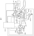
図1は、本発明の前提となる筒内噴射式内燃機関507の制御システムの全体構成を示したものである。筒内噴射式内燃機関507は4気筒からなり、各シリンダ507bに導入する空気は、エアクリーナ502の入口部から取り入れられ、吸気温度を測定するための温度センサ518も付随する空気流量計(エアフロセンサ)503を通り、吸気流量を制御する電制スロットル弁505aが収容されたスロットルボディ505を通ってコレクタ506に入る。
FIG. 1 shows the overall configuration of a control system for a direct injection
コレクタ506に吸入された空気は、内燃機関507の各シリンダ507bに接続された各吸気管501に分配された後、ピストン507a、シリンダ507b等によって形成される燃焼室507cに導かれる。
The air sucked into the
また、エアフロセンサ503からは、吸気流量を表す信号が高圧燃料ポンプ制御装置を有するコントロールユニット515に出力されている。さらに、スロットルボディ505には、電制スロットル弁505aの開度を検出するスロットルセンサ504が取り付けられており、その信号もコントロールユニット515に出力されるようになっている。
Further, the
一方、ガソリン等の燃料は、燃料タンク50から低圧燃料ポンプ51により一次加圧されて燃圧レギュレータ52により一定の圧力(例えば3kg/cm2)に調圧されるとともに、後述する高圧燃料ポンプ1でより高い圧力(例えば50kg/cm2)に2次加圧され、蓄圧室であるコモンレール53を介して各シリンダ507bに設けられている燃料噴射弁(以下、インジェクタと呼ぶ)54から燃焼室507cに噴射される。燃焼室507cに噴射された燃料は、点火コイル522で高電圧化された点火信号により点火プラグ508で着火される。
On the other hand, fuel such as gasoline is primarily pressurized from a
内燃機関507のクランク軸507dに取り付けられたクランク角センサ(以下ポジションセンサと呼ぶ)516は、クランク軸507dの回転位置を表す信号をコントロールユニット515に出力し、また、排気弁526の開閉タイミングを可変にする機構を備えたカム軸(図示省略)に取り付けられたクランク角センサ(以下フェーズセンサと呼ぶ)511は、前記カム軸の回転位置を表す角度信号をコントロールユニット515に出力するとともに、排気弁526のカム軸の回転に伴って回転する高圧燃料ポンプ1のポンプ駆動カム100の回転位置を表す角度信号をもコントロールユニット515に出力する。
A crank angle sensor (hereinafter referred to as a position sensor) 516 attached to the
尚、参照番号504は吸気圧センサであり吸気通路の圧力を計測し、また参照番号56は燃圧センサであり燃料圧力を計測し、それぞれコントロールユニット515に入力している。参照番号55はリリーフ弁であり所定燃圧に達すると燃料を燃料タンクに戻す機能を備えている。
図2に示すように、コントロールユニット515の主要部は、MPU603、EP−ROM602、RAM604及びA/D変換器を含むI/OLSI601等で構成され、ポジションセンサ516、フェーズセンサ511、水温センサ517、並びに燃圧センサ56を含む各種のセンサ等からの信号を入力として取り込み、所定の演算処理を実行し、この演算結果として算定された各種アクチュエータの制御信号を出力し、アクチュエータであるスピル弁(以下、高圧ポンプソレノイドという)200、各インジェクタ54及び点火コイル522等に所定の制御信号を供給して、燃料吐出量制御、燃料噴射量制御及び点火時期制御等を実行するものである。
As shown in FIG. 2, the main part of the
図3は高圧燃料ポンプ1を備えた燃料系システム全体の構成図を示している。
FIG. 3 shows a configuration diagram of the entire fuel system including the high-
高圧燃料ポンプ1は燃料タンク50から燃料配管9を介して送られてくる燃料を加圧してコモンレール53に高圧の燃料を圧送するものであり、燃料吸入通路10、吐出通路11、及び加圧室12が形成されている。
The high-
加圧室12には加圧部材であるプランジャ2が摺動可能に保持されており、吐出通路11には吐出弁16が設けられている。また、吸入通路10には燃料の吸入を制御する高圧ポンプソレノイド8が設けられている。高圧ポンプソレノイド8はノーマルクローズ型の電磁弁であり、非通電時に閉弁方向に力が作用し、通電時には開弁方向に力が作用する。
A
高圧ポンプソレノイド8は燃料吸入通路10と加圧室12の間の連通状態を制御するもので、弁体5と可動コア91、戻しばね92及び電磁コイル200より構成されている。
The high-pressure pump solenoid 8 controls the communication state between the
燃料はタンク50から低圧ポンプ51にてポンプ本体1の燃料導入口にプレッシャレギュレータ52で一定の圧力に調圧されて導かれる。また、ポンプ本体1の燃料導入口には燃料温度を測定するための温度センサ519が備え付けられている。
The fuel is led from the
その後、燃料はポンプ本体1にて加圧されて燃料吐出口からコモンレール53に圧送される。よって、高圧燃料系とは高圧ポンプからコモンレールまでと定義する。
Thereafter, the fuel is pressurized by the
コモンレール53にはインジェクタ54、圧力センサ56、圧力調整弁(以下リリーフ弁と呼ぶ)55が装着されている。リリーフ弁55はコモンレール53内の燃圧が所定値を超えた際に開弁し、高圧燃料系の破損を防止する。インジェクタ54は内燃機関の気筒数にあわせて装着されており、コントロールユニット515から与えられる駆動電流によってインジェクタ54内部のニードルが上方に移動することによって開弁し、燃料を噴射する。圧力センサ56は取得した圧力データをコントロールユニット515に出力する。
An
コントロールユニット515は各種センサから得られる内燃機関状態量(例えばクランク回転角、スロットル開度、内燃機関回転数、燃圧等)に基づいて適切な噴射燃料量や燃圧等を演算し、高圧ポンプ1やインジェクタ54を制御する。
The
プランジャ2は内燃機関507における排気弁526のカム軸の回転に伴って回転するポンプ駆動カム100に圧接されたリフタ3を介して往復動し、加圧室12の容積を変化させている。排気弁のカム軸は、図示しないがクランク軸507dとベルトを介してつながれており、ポンプ駆動カム100の回転は内燃機関507の回転と連動する。
The
プランジャ2が下降して加圧室12の容積が拡大すると、高圧ポンプソレノイド8が開弁し、燃料吸入通路10から加圧室12に燃料が流入するが、このプランジャ2が下降する行程を以下では吸入行程という。
When the
プランジャ2が上昇して高圧ポンプソレノイド8が閉弁すると、加圧室12内の燃料は昇圧され、吐出弁6を通過してコモンレール53へ圧送されるが、このプランジャ2が上昇する行程を以下では圧縮行程という。
When the
図4は高圧燃料ポンプ1の動作タイミングチャートを示している。尚、ポンプ駆動カム100で駆動するプランジャ2の実際のストローク(実位置)は曲線になるが、上死点と下死点の位置を分かり易くするために、以下プランジャ2のストロークを直線的に表すこととする。
FIG. 4 shows an operation timing chart of the high-
図4からわかるように、高圧ポンプソレノイド8の駆動状態はオン-オフ的な駆動信号の印加によって高圧ポンプソレノイド8の駆動電流が制御され弁体5の移動も変位もこれに合わせて変位するようになる。この制御状態とプランジャ12のストロークの関係は図示の通りである。
As can be seen from FIG. 4, the driving state of the high pressure pump solenoid 8 is controlled so that the driving current of the high pressure pump solenoid 8 is controlled by applying an on-off driving signal, so that the movement and displacement of the
つまり、圧縮行程中に高圧ポンプソレノイド8が閉じれば、吸入行程中に加圧室12に吸入された燃料は加圧され、コモンレール53側へ吐出される。そして圧縮行程中に高圧ポンプソレノイド8が開弁していれば、その間にわたり燃料は吸入通路10側へ押し戻され、加圧室12内の燃料はコモンレール53側へは吐出されない。
That is, if the high pressure pump solenoid 8 is closed during the compression stroke, the fuel sucked into the pressurizing
このように、ポンプ1の燃料吐出は高圧ポンプソレノイド8の開閉によって制御される。また、高圧ポンプソレノイド8の開閉はコントロールユニット515によって操作される。
In this way, fuel discharge from the
図3にあるように、高圧ポンプソレノイド8は弁体5、弁体5を閉弁方向に付勢する戻しばね92、電磁コイル200、可動コア91を構成部品として有している。電磁コイル200に電流が流れると、可動コア91に電磁力が発生して図中右側に引き寄せられ、可動コア91と一体に形成された弁体5が開弁する。電磁コイル200に電流が流れないと、弁体5を閉弁方向に付勢する戻しばね92により弁体5は閉じられる状態となる。高圧ポンプソレノイド8は駆動電流を流さない状態で閉弁する構造の弁であるため、ノーマルクローズ型の高圧ポンプソレノイド8といわれている。
As shown in FIG. 3, the high-pressure pump solenoid 8 includes a
吸入行程中は、加圧室12の圧力が吸入通路10の圧力よりも低くなり、その圧力差によって弁体5が開弁し、燃料が加圧室12に吸入される。このとき、ばね92は弁体5を閉弁方向に付勢するが、圧力差による開弁力の方が大きくなるように設定されているため、弁体5は開弁する。ここで、もし電磁コイル200に駆動電流が流れていれば、磁気吸引力が開弁方向へ作用して弁体5は更に開弁しやすくなる。
During the suction stroke, the pressure in the pressurizing
一方、圧縮行程中は加圧室12の圧力の方が吸入通路10よりも高くなるため、弁体5を開弁させる差圧は発生しない。ここで、電磁コイル200に駆動電流が流れていなければ、弁体5を閉弁方向に付勢するばね力などにより弁体5は閉弁する。これに対して電磁コイル200に駆動電流が流れて十分な磁気吸引力が発生していれば、磁気吸引力により弁体5は開弁方向に付勢される。
On the other hand, during the compression stroke, the pressure in the pressurizing
よって、吸入行程中に高圧ポンプソレノイド8の電磁コイル200に駆動電流を与え始めて圧縮行程中も与え続けると弁体5は開弁保持される。その間、加圧室12内の燃料は低圧通路10に逆流するため、燃料はコモンレール53内へ圧送されない。
Therefore, if the drive current starts to be applied to the
一方、圧縮行程中のあるタイミングで駆動電流を与えるのを停止すると、弁体5は閉弁して加圧室12内の燃料が加圧されて吐出通路11側へ吐出される。駆動電流を与えるのを停止するタイミングが早いと加圧される燃料の容量が大きく、タイミングが遅いと加圧される燃料の容量が小さくなる。
On the other hand, when the application of the drive current is stopped at a certain timing during the compression stroke, the
よって、コントロールユニット515は弁体5が閉じるタイミングを制御することによりポンプ1の吐出流量を制御することができる。
Therefore, the
さらに、圧力センサ56の信号に基づき、コントロールユニット515にて適切な通電OFFタイミングを演算して電磁コイル200をコントロールすることにより、コモンレール53の圧力を目標値にフィードバック制御させることができる。
Furthermore, the
図5は高圧燃料ポンプの制御装置を有するコントロールユニット515のMPU603が実施する高圧燃料ポンプの制御手段1502の制御ブロック図の一態様である。
FIG. 5 is an example of a control block diagram of the control means 1502 of the high pressure fuel pump implemented by the
高圧燃料ポンプの制御手段700は、燃圧センサ56からの信号をフィルタ処理して実燃圧を出力する燃圧入力処理手段701、内燃機関回転数と負荷からその動作点に最適な目標燃圧を算出する目標燃圧算出手段702、ポンプの吐出流量を制御するための位相パラメータを演算するポンプ制御角度算出手段703、ポンプ駆動信号であるデューティ信号のパラメータを演算するポンプ制御DUTY算出手段704、筒内噴射内燃機関507の状態を判定してポンプ制御モードを遷移させるポンプ状態遷移判定手段705、電磁コイル200にデューティ信号から生成される電流を与える高圧ポンプソレノイド駆動手段706から構成される。
The high-pressure fuel pump control means 700 filters the signal from the
図6にポンプ制御角度算出手段703の一態様を示しており、ポンプ制御角度算出手段703は通電開始角度算出手段801および通電終了角度算出手段802から構成されており、夫々の構成は以下に示すとおりである。 FIG. 6 shows one mode of the pump control angle calculation means 703. The pump control angle calculation means 703 is composed of an energization start angle calculation means 801 and an energization end angle calculation means 802, each of which is shown below. It is as follows.
図7に通電開始角度算出手段801の一態様を示しており、内燃機関回転数とバッテリ電圧を入力とした基本通電開始角度算出マップ901から基本通電開始角度STANGMAPを演算し、ポンプ駆動カム軸の可変バルブタイミング機構による位相差EXCAMADV分を補正することにより通電開始角度STANGを演算する。
FIG. 7 shows an embodiment of the energization start angle calculation means 801. The basic energization start angle STANGMAP is calculated from the basic energization start
可変バルブタイミング機構による位相差の補正は、動作角「0」位置に対して進角側に動作する場合はマップ検索された基本通電開始角度から所定位相量を減算し、遅角側に動作する可変バルブタイミング機構であればマップ検索された基本通電開始角度から所定位相量を加算する。本実施例では遅角側に動作する可変バルブタイミング機構を前提としている。 The phase difference correction by the variable valve timing mechanism is performed on the retard side by subtracting a predetermined phase amount from the basic energization start angle searched on the map when operating on the advance side with respect to the operating angle “0” position. In the case of the variable valve timing mechanism, a predetermined phase amount is added from the basic energization start angle retrieved from the map. The present embodiment is premised on a variable valve timing mechanism that operates on the retard side.
図8に、基本通電開始角度STANGMAPの設定方法について示しており、基本通電開始角度STANGMAPは可変バルブタイミング機構による位相差が「0」のときには通電開始角度STANGと等しい値となっている。今回使用する高圧ポンプは上述したようにノーマルクローズ式であるため、矢印で示しているようにポンププランジャの下死点までに高圧ポンプソレノイド8を開弁することが可能となる力が働くよう設定する。 FIG. 8 shows a method of setting the basic energization start angle STANGMAP. The basic energization start angle STANGMAP is equal to the energization start angle STANG when the phase difference due to the variable valve timing mechanism is “0”. Since the high-pressure pump used this time is normally closed as described above, it is set so that the force that can open the high-pressure pump solenoid 8 by the bottom dead center of the pump plunger works as shown by the arrow. To do.
高圧ポンプソレノイド8の開弁することが可能となる力は、回転数に比例しておおきくなり閉弁方向に働くポンプ内流体力に勝る力である。よって、電磁コイル200に発生する力は電流に比例するので、ポンプ下死点までに電磁コイル200に一定値以上の電流が流れている必要がある。この一定値まで到達する時間は、電磁コイル200に対する電源であるバッテリの電圧に依存し、一定値は回転数に依存するので、結果として基本通電開始角度算出マップ901、内燃機関の回転数とバッテリ電圧を入力とするマップに決められている。
The force that enables the high-pressure pump solenoid 8 to open is a force that is proportional to the rotational speed and is superior to the fluid force in the pump that works in the valve closing direction. Therefore, since the force generated in the
図9に先に説明した図6の通電終了角度算出手段802の一態様を示しており、今回使用する高圧ポンプでは通電終了角度を変化させることにより吐出量を制御するように構成されている。 FIG. 9 shows one mode of the energization end angle calculation means 802 of FIG. 6 described above. The high pressure pump used this time is configured to control the discharge amount by changing the energization end angle.
燃圧F/B制御中は、インジェクタ54による噴射量と内燃機関の回転数を入力とした基本角度マップ1101より基本角度BASANGを演算する。基本角度BASANGは、定常運転状態における要求吐出量に対応する閉弁角度を設定する。
During the fuel pressure F / B control, the basic angle BASANG is calculated from the
燃圧F/B制御演算部1102では、目標燃圧と実燃圧より演算されたF/B分を基本角度BASANGに加算することにより基準角度REFANGを演算する。
The fuel pressure F / B
基準角度REFANGは可変バルブタイミング動作が無いと仮定した場合の、基準REFからの高圧ポンプソレノイド8を閉弁したい角度を示している。ここで基準REFとは、位相制御の基準点となる位置である。コントロールユニット515において、要求された位相に制御出力を出力するためには基準点の設定が必要である。
The reference angle REFANG indicates an angle at which the high pressure pump solenoid 8 from the reference REF is desired to be closed when it is assumed that there is no variable valve timing operation. Here, the reference REF is a position serving as a reference point for phase control. In the
図10に基準点生成方法の一例を示しており、クランク角センサ信号には歯欠け部分(通常のクランク角センサ信号間隔より間隔を広くした部分)が存在する。内燃機関始動時から初回歯欠け認識時のクランク角センサを基準点(基準REF)とし、以後一定角度毎にクランク角センサ値から基準REFを生成し、歯欠け認識はクランク角センサ入力間隔より判定するようになっている。 FIG. 10 shows an example of the reference point generation method. The crank angle sensor signal has a missing tooth portion (a portion having a wider interval than the normal crank angle sensor signal interval). The crank angle sensor from the start of the internal combustion engine to the first missing tooth recognition is used as a reference point (reference REF), and thereafter, the reference REF is generated from the crank angle sensor value at every fixed angle, and the missing tooth recognition is determined from the crank angle sensor input interval. It is supposed to be.
また、通電終了角度算出手段802は閉弁遅れ演算テーブル1103、強制OFFタイミングマップ1104、及び出力終了角度算出部1105を備えている。
The energization end
燃圧F/B制御演算部1102で求められた基準角度REFANGに、内燃機関回転数を入力とした閉弁遅れ演算テーブル1103より演算した閉弁遅れPUMDLYと可変バルブタイミング動作角を加減算することにより出力終了角度算出部1105で通電終了角度OFFANGを演算する。
また、出力終了角度算出部1105で算出される通電終了角度OFFANGは強制OFFタイミングマップ1104でマップ検索された出力強制終了角度CPOFFANGを上限値に持つようになっている。この出力強制終了角度CPOFFANGは回転数とバッテリ電圧を入力としたマップ値に可変バルブタイミング動作角を加算した値である。
Output by adding / subtracting the valve closing delay PUMDLY calculated from the valve closing delay calculation table 1103 to which the internal combustion engine speed is input and the variable valve timing operating angle to the reference angle REFANG obtained by the fuel pressure F / B
Further, the energization end angle OFFANG calculated by the output end
図11に出力強制終了角度CPOFFANGの設定方法について示しており、出力強制終了角度CPOFFANGを設定する目的は、通電を止めた場合においても無吐出になる角度領域は通電を止めて消費電力の低減や電磁コイル200の発熱防止を図る目的である。
FIG. 11 shows a method for setting the output forced end angle CPOFFANG. The purpose of setting the output forced end angle CPOFFANG is to reduce the power consumption by stopping the energization in the angle region where no discharge occurs even when the energization is stopped. The purpose is to prevent heat generation of the
図11の矢印に示すように上死点以前に駆動信号を停止しても閉弁遅れがあるため上死点付近まで開弁して高圧ポンプは無吐出運転となる。このため、出力強制終了角度CPOFFANGは無吐出運転を要求される燃料カット時にも使用され、この角度で電磁コイル200への通電を終了する。
As shown by the arrow in FIG. 11, even if the drive signal is stopped before the top dead center, there is a valve closing delay, so that the valve is opened to the vicinity of the top dead center and the high-pressure pump is in a non-discharge operation. For this reason, the output forced end angle CPOFFANG is also used at the time of fuel cut that requires non-discharge operation, and energization of the
図12にF/B制御中における電磁コイル200への通電信号のタイムチャートを示している。
FIG. 12 shows a time chart of the energization signal to the
通電開始角度STANGからF/B制御中の燃料吐出量を制御する通電終了角度OFFANGまでオープン電流制御デューティが出力されている。オープン電流制御デューティは、電気的な信号として初期通電時間TPUMONおよび初期通電後のデューティにより形成されている。ここで、初期通電時間TPUMONおよび初期通電後のデューティ比PUMDTYは、図5に示したポンプ制御DUTY算出手段704で演算されて電磁コイル200に供給されるものである。
The open current control duty is output from the energization start angle STANG to the energization end angle OFFANG for controlling the fuel discharge amount during F / B control. The open current control duty is formed as an electrical signal by the initial energization time TPUMON and the duty after the initial energization. Here, the initial energization time TPUMON and the duty ratio PUMDTY after the initial energization are calculated by the pump control DUTY calculating means 704 shown in FIG. 5 and supplied to the
以上述べた基本的なポンプ制御手段1502の構成は本出願人が既に出願して公開されているものであるので詳細な説明は省略する。 Since the basic pump control means 1502 described above has already been filed and published by the present applicant, a detailed description thereof will be omitted.
ところで、上述したようにハイブリッド車や、デュアルインジェクション式の燃料噴射制御装置の場合、筒内用燃料噴射弁が燃料を噴射しない状態、つまり高圧ポンプ系を使用しない運転状態が長くなる傾向となっている。 Incidentally, as described above, in the case of a hybrid vehicle or a dual injection type fuel injection control device, the in-cylinder fuel injection valve tends not to inject fuel, that is, the operating state in which the high-pressure pump system is not used tends to be long. Yes.
筒内用燃料噴射弁を有する内燃機関において、筒内に燃料を噴射しない状態が長く続いた場合、筒内用燃料噴射弁に燃料を供給する高圧燃料ポンプ内および蓄圧室内の燃料温度が上昇する傾向になる。 In an internal combustion engine having an in-cylinder fuel injection valve, when the state in which fuel is not injected into the cylinder continues for a long time, the fuel temperature in the high-pressure fuel pump and the pressure accumulating chamber that supply fuel to the in-cylinder fuel injection valve rises. Become a trend.
これは、筒内用燃料噴射弁から燃料を噴射しないため、高圧ポンプの高圧ポンプソレノイド8を開いて高圧燃料ポンプから燃料を蓄圧室側に吐出させない状態に制御しても、高圧燃料ポンプの動作は内燃機関の回転と連動しており、燃料を吐出しなくても高圧燃料ポンプは空回りするからである。 This is because the fuel is not injected from the in-cylinder fuel injection valve. Therefore, even if the high pressure pump solenoid 8 of the high pressure pump is opened and the fuel is not discharged from the high pressure fuel pump to the pressure accumulating chamber side, the operation of the high pressure fuel pump is performed. Is linked to the rotation of the internal combustion engine, and the high-pressure fuel pump idles without discharging the fuel.
高圧燃料ポンプ内の燃料温度が上昇した場合、燃料の粘性が低下し、ポンプの摺動部で十分な潤滑油膜が確保できず、ポンプ摺動部の摩擦が増大し、燃費の悪化を招くようになる。 If the fuel temperature in the high-pressure fuel pump rises, the viscosity of the fuel will decrease, and a sufficient lubricating oil film will not be secured at the sliding part of the pump, and the friction at the pump sliding part will increase, leading to deterioration of fuel consumption. become.
また、蓄圧室内の燃料温度が上昇した場合、燃料の粘性が低下し、燃料噴射弁の噴射口からリークが発生し、排気ガスの悪化を招く。加えて燃料が熱膨張することにより、燃料圧力が上昇するため最適な燃圧ではなくなり、次回の燃料噴射時に排気ガスの悪化を招くようになる。 Further, when the fuel temperature in the pressure accumulating chamber rises, the viscosity of the fuel decreases, leaks occur from the injection port of the fuel injection valve, and exhaust gas deteriorates. In addition, since the fuel expands due to thermal expansion, the fuel pressure rises, so that the fuel pressure is not optimal and the exhaust gas deteriorates at the next fuel injection.
本発明はこのような問題に対して提案されたもので、その特徴は筒内用燃料噴射弁から燃料を噴射しない期間が所定期間以上にわたって継続した場合に、高圧ポンプの作動を再開して高圧燃料系の内部の燃料温度の過度な上昇を抑制するようにしたところにある。以下、図面にしたがい本発明の一実施例を詳細に説明する。 The present invention has been proposed for such a problem. The feature of the present invention is that the operation of the high-pressure pump is resumed when the period during which fuel is not injected from the in-cylinder fuel injection valve continues for a predetermined period or longer. An excessive rise in fuel temperature inside the fuel system is suppressed. Hereinafter, an embodiment of the present invention will be described in detail with reference to the drawings.
図13に本発明の一実施例になる燃料噴射制御手段の制御ブロック図を示しており、高圧燃料系内部燃料温度制御手段1301に内燃機関の運転状態が入力されることにより、高圧燃料ポンプ制御手段1302、インジェクタ制御手段1303、点火コイル制御手段1304、電気的な回生装置制御手段1305、及びMPI制御手段1306が制御されるようになっている。
FIG. 13 shows a control block diagram of the fuel injection control means according to one embodiment of the present invention. When the operating state of the internal combustion engine is input to the high pressure fuel system internal fuel temperature control means 1301, high pressure fuel pump control is performed.
電気的な回生装置は例えばHEV車に搭載されている電動/発電機であり、これは電動機で走行している間において内燃機関は停止され、内燃機関で走行している間においては発電機として機能して二次電池に充電するものである。尚、破線で示したMPIは筒内用燃料噴射弁に加えて吸気ポート用燃料噴射弁を気筒毎に有するデュアルインジェクション式の燃料噴射制御装置を示している。 The electric regeneration device is, for example, an electric motor / generator mounted on an HEV vehicle, and the internal combustion engine is stopped while running on the electric motor, and as an electric generator while running on the internal combustion engine. It functions and charges the secondary battery. Note that MPI indicated by a broken line indicates a dual injection type fuel injection control apparatus having an intake port fuel injection valve for each cylinder in addition to the in-cylinder fuel injection valve.
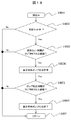
図14に本発明の第1の実施形態である高圧燃料系内部燃料温度制御手段1301の制御フローチャートを示している。 FIG. 14 shows a control flowchart of the high-pressure fuel system internal fuel temperature control means 1301 according to the first embodiment of the present invention.
ステップ1401は割込み処理の起動であり、例えば10ms周期または基準REF周期でこの制御フローチャートが起動されて以下の演算が行われる。
ステップ1602において、内燃機関が燃料カット中であるかどうか判定する。この燃料カットは内燃機関が動作している時の減速中の燃料カットではなく、HEV車であれば電動機で走行している状態や、デュアルインジェクション式の燃料噴射装置においてMPI方式で燃料が内燃機関に供給されている状態を指している。要は内燃機関が停止状態或いは筒内噴射が停止状態にあることを意味している。
In
ステップ1602で燃料カット中と判断された場合、ステップ1403に進み、燃料カットをしている時間がINJTIME1以上であるか判定する。このINJTIME1は筒内用燃料噴射弁から燃料を噴射しない期間が所定期間(一定期間、可変期間を含む概念)以上にわたって継続した期間を示し、燃料の噴射を再開して高圧燃料系の内部の燃料温度の過度な上昇を抑制するための判断基準となっている。
If it is determined in
ステップ1403でINJTIME1以上であると判定されるとステップ1404に進んで高圧燃料系の温度を下げるため燃料噴射を許可する。したがって、この時、高圧燃料ポンプ1は有効な吐出動作を開始してコモンレール53内の燃料圧を高めることができる。ここで、高圧ポンプソレノイド8を動作が有効になるように開閉すれば正常な吐出圧が得られ、高圧ポンプソレノイド8を全開状態に維持すれば加圧室12の燃料は元に戻され無効なポンプ動作となる。
If it is determined in
このように、燃料噴射が再開されると燃料が消費されるため燃料タンク内の温度が低い燃料が高圧ポンプ1やコモンレール53に循環するように導入されるため温度を下げることができるようになる。
As described above, when the fuel injection is resumed, the fuel is consumed, so that the fuel having a low temperature in the fuel tank is introduced so as to circulate to the high-
ステップ1405では、燃料カットの要求にそった種々の条件成立のもとで、ステップ1404で許可された燃料噴射中での燃料カット要求の有無を判定する。
In
このステップ1405において燃料カットの要求が有ると判定した場合、ステップ1406に進み、再開した燃料噴射の燃料噴射時間がINJTIME2以上であるか判定する。このINJTIME2は高圧燃料系の温度を冷却するに必要な燃料量を表す時間として設定される。
If it is determined in
ステップ1406において、INJTIME2で設定された時間以上に亘って燃料が噴射されたと判断されるとステップ1407に進んで燃費を向上するため燃料カットを許可する。
If it is determined in
このように、INJTIME1は燃料カットを行なっている時間或いは期間の長さを表し、INJTIME2は燃料噴射を行なっている時間或いは期間の長さを表している。 Thus, INJTIME1 represents the length of time or period during which fuel cut is performed, and INJTIME2 represents the length of time or period during which fuel injection is performed.
そして、この燃料カットが終了するとステップ1408に進んでリターンとなり、再びステップ1401の割込み処理の起動を待つようになる。
図15にステップ1403で使用されるINJTIME1のINJTIME1算出手段1500の構成を示している。
When this fuel cut is completed, the routine proceeds to step 1408, where the process returns, and again waits for the start of interrupt processing at
FIG. 15 shows the configuration of INJTIME1 calculating means 1500 of INJTIME1 used in
INJTIME1−1算出手段1501乃至INJTIME1−4算出手段1504においては、高圧燃料系内温度に影響を与える変数(パラメータ)である内燃機関の回転数、内燃機関の冷却水温度、内燃機関の吸気温度、及び燃料温度を入力とした燃料カット許容時間INJTIME1−1乃至INJTIME1−4が格納されたテーブルを示しており、これらのテーブルから燃料カット許容時間INJTIME1-1乃至INJTIME1-4が検索される。 In the INJTIME1-1 calculating means 1501 to INJTIME1-4 calculating means 1504, the rotational speed of the internal combustion engine, the cooling water temperature of the internal combustion engine, the intake air temperature of the internal combustion engine, which are variables (parameters) that affect the internal temperature of the high-pressure fuel system, And fuel cut allowable times INJTIME1-1 to INJTIME1-4 using the fuel temperature as an input are stored, and fuel cut allowable times INJTIME1-1 to INJTIME1-4 are searched from these tables.
また、INJTIME1−5算出手段1505では燃料圧力を入力とした閾値(規定値)が設定されており、この閾値を超えた場合にはINJTIME1−5算出手段1505はINJTIME1−5=0を出力する。つまり、温度上昇によって燃圧が高くなりすぎたことを判断するものである。 The INJTIME1-5 calculating unit 1505 sets a threshold value (specified value) with the fuel pressure as an input. When this threshold value is exceeded, the INJTIME1-5 calculating unit 1505 outputs INJTIME1-5 = 0. That is, it is determined that the fuel pressure has become too high due to the temperature rise.
INJTIME1−6算出手段1506では内燃機関の回転数を積算することにより算出される高圧燃料ポンププランジャ摺動回数を入力とし閾値(規定値)が設定されており、この閾値を超えた場合にはINJTIME1−6算出手段1506はINJTIME1−6=0を出力する。これも温度上昇によって燃圧が高くなりすぎたことを判断するものである。つまりプランジャの摺動回数は摩擦熱を積算することになるのでこれも間接的に温度上昇によって燃圧が高くなりすぎたことを判断するものである。
In the INJTIME 1-6 calculating means 1506, a threshold value (predetermined value) is set by inputting the number of sliding times of the high-pressure fuel pump plunger calculated by accumulating the number of revolutions of the internal combustion engine. If this threshold value is exceeded,
更に、場合によってはINJTIME1−7算出手段1507では時間そのものがセットされており、前回の燃料カット開始点からの積算時間がこのセットされた時間を超えるとINJTIME1−7=0を出力するか、或いは予め定めた時間を最小値選択手段に出力するようにしている。 Further, in some cases, the time itself is set in the INJTIME1-7 calculating means 1507, and if the accumulated time from the previous fuel cut start point exceeds the set time, INJTIME1-7 = 0 is output, or A predetermined time is output to the minimum value selection means.
このセットされる時間は高圧ポンプ1やコモンレール53の燃料温度が時間経過と共に上昇していき所定の温度になった時間に決められており、この時間をセットするようにしている。よって、この時間は経験的、或いは実験的に割り出された時間である。
The set time is set to a time when the fuel temperature of the high-
最小値選択手段1508では、INJTIME1−1乃至INJTIME1−7の最小値をINJTIME1として出力する。これは高圧燃料系の安全性を見込んで最小値を選択するようにしたものである。 The minimum value selection means 1508 outputs the minimum values of INJTIME1-1 to INJTIME1-7 as INJTIME1. The minimum value is selected in consideration of the safety of the high-pressure fuel system.
また、この最小値選択手段1508において、INJTIME1-5、及びINJTIME1-6、場合によってINJTIME1-7は「0」以外の値のときは採用しない。このようにすることで、INJTIME1-5、INJTIME1-6、またはINJTIME1-7が「0」となった場合に、INJTIME1=0となって最小値となり燃料噴射が許可されることとなる。 Further, in this minimum value selection means 1508, INJTIME1-5, INJTIME1-6, and in some cases INJTIME1-7 are not adopted when the value is other than “0”. By doing so, when INJTIME1-5, INJTIME1-6, or INJTIME1-7 becomes “0”, INJTIME1 = 0 and becomes the minimum value, and fuel injection is permitted.
図16にステップ1406で使用されるINJTIME2のINJTIME2算出手段1600の構成を示している。
FIG. 16 shows the configuration of INJTIME2 INJTIME2 calculation means 1600 used in
INJTIME2-1算出手段1601乃至INJTIME2-5算出手段1605においては、高圧燃料系内温度に影響を与えるパラメータである内燃機関回転数、冷却水温度、内燃機関の吸気温度、燃料温度、燃料カット中に算出したポンププランジャ摺動回数を入力とした、必要燃料噴射時間INJTIME2-1乃至INJTIME2-5が格納されたテーブルを示しており、これらのテーブルから必要燃料噴射時間INJTIME2-1乃至INJTIME2-5が検索される。 In the INJTIME2-1 calculating means 1601 to the INJTIME2-5 calculating means 1605, the internal combustion engine speed, the cooling water temperature, the intake air temperature of the internal combustion engine, the fuel temperature, and the fuel cut which are parameters affecting the high-pressure fuel system temperature Tables in which the required fuel injection times INJTIME2-1 to INJTIME2-5 are stored using the calculated pump plunger sliding times as input are shown, and the required fuel injection times INJTIME2-1 to INJTIME2-5 are searched from these tables. Is done.
INJTIME2-6算出手段1606では、燃料圧力を入力とした閾値(規定値)が設定されており、この閾値を下回った場合にはINJTIME2−6算出手段1606はINJTIME2−6=0を出力する。この場合はコモンレール53や高圧ポンプ1の圧力が下がるので燃料カットを再開しても問題ないからで、「0」をセットして後述する最小値選択手段1608によって燃料カットを実行できるようにしている。
In the INJTIME2-6 calculation means 1606, a threshold value (specified value) with the fuel pressure as an input is set. When the threshold value is below this threshold value, the INJTIME2-6 calculation means 1606 outputs INJTIME2-6 = 0. In this case, since the pressure of the
最大値選択手段1607では、INJTIME2-1乃至INJTIME2-5の最大値をINJTIME2-7として出力する。最大値を選択するのは燃料噴射時間を十分取ってコモンレール53や高圧ポンプ1の冷却を十分に行なうことを狙っている。
Maximum value selection means 1607 outputs the maximum value of INJTIME2-1 to INJTIME2-5 as INJTIME2-7. The purpose of selecting the maximum value is to sufficiently cool the
最小値選択手段1608では、INJTIME2-7とINJTIME2-6の最小値をINJTIME2として出力する。またこの最小値選択手段1608において、INJTIME2-6は「0」以外の値のときは採用しない。このようにすることで、INJTIME2-6が「0」となった場合、INJTIME2=0となって燃料カットを許可することとなる。 The minimum value selection means 1608 outputs the minimum value of INJTIME2-7 and INJTIME2-6 as INJTIME2. Also, in this minimum value selection means 1608, INJTIME2-6 is not adopted when the value is other than “0”. In this way, when INJTIME2-6 becomes “0”, INJTIME2 = 0 and fuel cut is permitted.
このように、本実施例では筒内用燃料噴射弁から燃料を噴射しない期間が所定期間以上にわたって継続した場合に、燃料の噴射を再開して高圧燃料系の内部の燃料温度の過度な上昇を抑制するようにした。 As described above, in this embodiment, when the period in which the fuel is not injected from the in-cylinder fuel injection valve continues for a predetermined period or longer, the fuel injection is resumed to excessively increase the fuel temperature inside the high-pressure fuel system. I tried to suppress it.
これによって、高圧燃料ポンプ内の燃料温度が上昇した場合に燃料の粘性が低下し、ポンプの摺動部で十分な潤滑油膜が確保できず、ポンプ摺動部の摩擦が増大して燃費の悪化を招く、或いは蓄圧室内の燃料温度が上昇した場合に燃料の粘性が低下し、燃料噴射弁の噴射口からリークが発生し、排気ガスの悪化を招く、といった課題を解決できるものである。 As a result, when the fuel temperature in the high-pressure fuel pump rises, the viscosity of the fuel decreases, a sufficient lubricating oil film cannot be secured at the sliding part of the pump, the friction at the pump sliding part increases, and the fuel consumption deteriorates. Or when the fuel temperature in the pressure accumulating chamber rises, the viscosity of the fuel decreases, a leak occurs from the injection port of the fuel injection valve, and the exhaust gas deteriorates.
図17に本発明の第2の実施形態である高圧燃料系内部燃料温度制御手段1301の制御フローチャートを示しているが、この実施例ではHEV車に搭載されている電動/発電機等の別駆動源と組み合わされた内燃機関を前提としている。 FIG. 17 shows a control flowchart of the high-pressure fuel system internal fuel temperature control means 1301 according to the second embodiment of the present invention. In this embodiment, another drive of the electric / generator mounted on the HEV vehicle is shown. It assumes an internal combustion engine combined with a source.
ステップ1701は割込み処理の起動であり、例えば10ms周期または基準REF周期でこの制御フローチャートが起動されて以下の演算が行われる。
ステップ1702において、内燃機関が燃料カット中であるかどうか判定する。この燃料カットはHEV車が電動機で走行している状態を示しており、内燃機関が停止状態にあることを意味している。
In
ステップ1702で燃料カット中と判断された場合、ステップ1703に進み、燃料カットをしている時間がINJTIME3以上であるか判定する。このINJTIME3は筒内用燃料噴射弁から燃料を噴射しない期間が所定期間(一定期間、可変期間を含む概念)以上にわたって継続した期間を示し、燃料の噴射を再開して高圧燃料系の内部の燃料温度の過度な上昇を抑制するための判断基準となっている。
If it is determined in
ステップ1703において、燃料カット時間がINJTIME3以上となった場合は、高圧燃料ポンプ1の作動を再開して燃料噴射が可能なように準備する。
In
次にステップ1704に進んでコモンレール53内の燃料圧力が最適な燃焼を実現するための目標燃圧以上となっているかを判定する。第1の実施例においては燃料カット時間がINJTIME1を越えれば燃料噴射を再開していたが本実施例では以下の制御を行うようになっている。
Next, the routine proceeds to step 1704, where it is determined whether the fuel pressure in the
つまり、INJTIME3を越えても燃料の圧力が目標燃圧以下の場合では高圧燃料ポンプ1のF/B制御を許可して目標燃圧へ制御するものである。そしてこの状態で通常の燃料噴射が実行されるようになっている。
That is, even if it exceeds INJTIME3, if the fuel pressure is equal to or lower than the target fuel pressure, the F / B control of the high-
一方、目標燃圧を越えて燃料の圧力が高い状態で燃料を噴射すると排気ガスの制御(有害ガス成分の制御)に悪影響を及ぼすため以下の制御を実行する。 On the other hand, if fuel is injected in a state where the fuel pressure exceeds the target fuel pressure and the fuel pressure is high, the following control is executed because it adversely affects exhaust gas control (control of harmful gas components).
ステップ1704において燃料圧力が目標燃圧以上と判断されるとステップ1705に遷移し、車両減速中であるか判定する。車両減速中である場合、ステップ1706において1サイクル中に複数回の噴射を実施する多段燃料噴射を許可する。ここで車両減速中に噴射を再開するのは、減速中は正のトルクが発生していないため車両駆動トルク制御精度を保ちやすいためである。
If it is determined in
次に、ステップ1707においては、燃料噴射許可後に電気的回生制御を許可する。そして、ステップ17076で実行された燃料噴射により発生したトルクは電気的な回生制御により吸収することにより燃費を向上させる。
Next, in
多段噴射は燃料カットにより冷却された燃焼室内への燃料付着を低減し、排出ガス性能の悪化を防止する。また、点火時期の圧縮上死点以降までの遅角を組み合わせることにより、燃料カットにより冷却された触媒を昇温すると共に正トルクの急激な発生を防止することができる。 Multi-stage injection reduces fuel adhesion to the combustion chamber cooled by the fuel cut and prevents deterioration of exhaust gas performance. In addition, by combining the retardation of the ignition timing up to the compression top dead center, it is possible to raise the temperature of the catalyst cooled by the fuel cut and to prevent rapid generation of positive torque.
そして、ステップ1707で電気的な回生制御の次にステップ1708に進んでリターンとなり、再びステップ1701の割込み処理の起動を待つようになる。
In
図18に本発明の第3の実施形態である高圧燃料系内部燃料温度制御手段1301の制御フローチャートを示している。 FIG. 18 shows a control flowchart of the high-pressure fuel system internal fuel temperature control means 1301 according to the third embodiment of the present invention.
ステップ1801は割込み処理の起動であり、例えば10ms周期または基準REF周期でこの制御フローチャートが起動されて以下の演算が行われる。
ステップ1802において、内燃機関が燃料カット中であるかどうか判定する。この燃料カットは内燃機関が停止状態、或いは筒内噴射が停止状態にあることを意味している。
In
ステップ1802で燃料カット中と判断された場合、ステップ1803に進み、燃料カットをしている時間がINJTIME4以上であるか判定する。このINJTIME4は筒内用燃料噴射弁から燃料を噴射しない期間が所定期間(一定期間、可変期間を含む概念)以上にわたって継続した期間を示し、燃料の噴射を再開して高圧燃料系の内部の燃料温度の過度な上昇を抑制するための判断基準となっている。そして、この具体的なINJTIME4の算出手段は実施例1で示したINJTIME1の算出手段と同様の方法で算出されるものである。
If it is determined in
ステップ1803でINJTIME4を経過したと判断された場合には、ステップ1804に遷移して高圧燃料系の温度を下げるため高圧燃料ポンプ1の吐出を許可する。この場合は通常通り高圧ポンプソレノイド8を作動させて吐出弁6から燃料をコモンレール53側に送り出すようになる。この時はコモンレール53内の燃料圧力を上げるためインジェクタ54は作動せずに閉じたままの状態にしてある。そして、燃料カット中に高圧燃料ポンプの吐出を許可した場合、コモンレール53内の燃料圧力が昇圧してリリーフ弁55が開弁し、コモンレール53及び高圧ポンプ1の燃料が燃料タンク内の比較的温度が低い燃料が循環してコモンレール53や高圧ポンプ内の燃料温度を下げることができる。
If it is determined in
ステップ1805では、高圧ポンプ1の作動時間(吐出時間)がINJTIME5以上継続したか判定する。INJTIME5以上継続した場合には高圧燃料系が充分に冷却されたと判断してステップ1806へ進み高圧燃料ポンプ1の吐出を終了する。尚、吐出を終了する条件としては吐出時間の代わりに吐出回数を用いても良いものである。
In
そして、この高圧燃料ポンプ1の吐出が終了するとステップ1807に進んでリターンとなり、再びステップ1801の割込み処理の起動を待つようになる。
Then, when the discharge of the high-
次にステップ1805で使用されるINJTIME5の算出方法について説明するが、図19にINJTIME5算出手段1900の構成を示している。
Next, an INJTIME5 calculation method used in
INJTIME5-1算出手段1901乃至INJTIME5-5算出手段1905においては、高圧燃料系内温度に影響を与えるパラメータである内燃機関の回転数、冷却水温度、内燃機関の吸気温度、燃料温度、燃料カット中に算出したポンププランジャ摺動回数を入力として決まる必要ポンプ作動時間INJTIME5-1乃至INJTIME5-5が格納されたテーブルを示しており、これらのテーブルから必要ポンプ作動時間INJTIME5-1乃至INJTIME5-5が検索される。
In the INJTIME5-1
最大値選択手段1906では、INJTIME5-1乃至INJTIME5-5の最大値をINJTIME5として出力する。最大値を選択する理由は確実に高圧燃料系内の温度を下げるために十分な燃料の循環を行なうためである。 Maximum value selection means 1906 outputs the maximum value of INJTIME5-1 to INJTIME5-5 as INJTIME5. The reason for selecting the maximum value is to perform sufficient fuel circulation in order to reliably lower the temperature in the high-pressure fuel system.
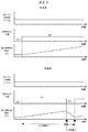
以上では複数の実施例に基づいて、筒内用燃料噴射弁から燃料を噴射しない期間が所定期間以上にわたって継続した場合に高圧燃料系の内部の燃料温度の過度な上昇を抑制するようにした例を説明した。次にこれを総括して本発明の効果の一例を図20により述べる。 In the above, based on a plurality of embodiments, an example in which an excessive increase in the fuel temperature inside the high-pressure fuel system is suppressed when a period in which fuel is not injected from the in-cylinder fuel injection valve continues for a predetermined period or more. Explained. Next, this will be summarized and an example of the effect of the present invention will be described with reference to FIG.
図20は本発明を実施した制御装置と、本発明を実施しない従来技術においての高圧燃料系の挙動を示したタイムチャートである。 FIG. 20 is a time chart showing the behavior of the control apparatus embodying the present invention and the high-pressure fuel system in the prior art not embodying the present invention.
従来技術においては、内燃機関が作動しない燃料カット状態が長時間継続した場合では高圧燃料系内部の燃料温度が時間と共に上昇していくようになる。このため、高圧燃料ポンプ内の燃料温度が上昇した場合、燃料の粘性が低下してポンプの摺動部で十分な潤滑油膜が確保できず、結果としてポンプ摺動部の摩擦が増大して燃費の悪化を招くようになる。 In the prior art, when the fuel cut state in which the internal combustion engine does not operate continues for a long time, the fuel temperature inside the high pressure fuel system rises with time. For this reason, when the fuel temperature in the high-pressure fuel pump rises, the viscosity of the fuel decreases and a sufficient lubricating oil film cannot be secured at the sliding part of the pump, resulting in increased friction at the pump sliding part and fuel consumption. Will be worse.
また、蓄圧室内の燃料温度が上昇した場合、燃料の粘性が低下して燃料噴射弁の噴射口からリークが発生し、この結果排気ガスの悪化を招く。加えて燃料が熱膨張することにより燃料圧力が上昇するため最適な燃圧ではなくなり、次回の燃料噴射時に排気ガスの悪化を招くようになる。 Further, when the temperature of the fuel in the pressure accumulating chamber rises, the viscosity of the fuel decreases and a leak occurs from the injection port of the fuel injection valve. As a result, the exhaust gas is deteriorated. In addition, since the fuel pressure rises due to thermal expansion of the fuel, the fuel pressure is not optimal, and the exhaust gas deteriorates during the next fuel injection.
一方、本発明においては内燃機関が作動しない燃料カット状態が所定期間(実施例1でいうINJTIME1)に亘って継続して燃料温度が上昇すると、燃料の温度を下げるように、高圧燃料ポンプやコモンレールの燃料を循環(実施例1においてはINJTIME2の期間に亘って燃料を噴射して燃料を循環させる)させるので高圧燃料系内部の燃料温度を適切な値に保つことができるようになる。
On the other hand, in the present invention, when the fuel cut state in which the internal combustion engine does not operate continues for a predetermined period (
これによって内燃機関の燃費を向上し、燃焼の安定化による運転性能の向上及び排出ガス性能の改善を図ることが期待できるようになる。 As a result, the fuel efficiency of the internal combustion engine can be improved, and it can be expected to improve the driving performance and the exhaust gas performance by stabilizing the combustion.
以上に亘り本発明の実施形態について詳述したが、本発明はこれらの実施形態に限定されるものではなく、特許請求の範囲に記載された本発明の精神を逸脱することなく種々の変更ができるものである。 Although the embodiments of the present invention have been described in detail above, the present invention is not limited to these embodiments, and various modifications can be made without departing from the spirit of the present invention described in the claims. It can be done.
特に本実施例においてはノーマルクローズ型ポンプを例として記載したが、駆動電流を流さない状態で開弁する構造の吸入弁を持つノーマルオープン型ポンプを用いた制御装置であっても本発明は適用できるものである。 In particular, in the present embodiment, a normally closed pump has been described as an example, but the present invention can be applied even to a control device using a normally open pump having a suction valve having a structure in which a valve is opened without a drive current flowing. It can be done.
以上の説明から理解されるように、本発明に係る内燃機関の燃料噴射制御装置は、筒内噴射式内燃機関の燃料カット中に、一時的に適切なタイミングで燃料を噴射することにより高圧燃料系の内部の燃料温度の過度な上昇を抑制することが可能となるので、燃料燃焼の安定化、排出ガスおよび燃費性能の改善に貢献することができるものである。 As can be understood from the above description, the fuel injection control apparatus for an internal combustion engine according to the present invention temporarily injects fuel at an appropriate timing during fuel cut of the direct injection internal combustion engine. Since it is possible to suppress an excessive increase in the fuel temperature inside the system, it is possible to contribute to stabilization of fuel combustion, improvement of exhaust gas and fuel consumption performance.
1…高圧燃料ポンプ、3…リフタ、4…下降ばね、 8…高圧ポンプソレノイド、51…低圧燃料ポンプ、53…コモンレール、54…インジェクタ、56…燃圧センサ、507…筒内噴射内燃機関、515…コントロールユニット、517…水温センサ、518…吸気温センサ、519…燃温センサ、522…点火コイル、1301…高圧燃料系内部燃料温度制御手段、1302…高圧燃料ポンプ制御手段、1303…インジェクタ制御手段、1304…点火コイル制御手段、1305…回生装置制御手段、1501〜1506…INJTME算出手段、1601〜1606…INJTME算出手段。
DESCRIPTION OF
Claims (17)
前記燃料噴射制御装置は、前記内燃機関が所定期間に亘り停止している状態が継続されると前記高圧ポンプを作動させて前記高圧ポンプに燃料タンクの燃料を循環させる機能を備えていることを特徴とする内燃機関の燃料噴射制御装置。 A fuel injection control device used for an internal combustion engine used in a vehicle of a type that extracts power by an electric motor, or an internal combustion engine having an in-cylinder fuel injection valve and an intake port fuel injection valve, the fuel injection control device Has at least a fuel injection valve for directly injecting fuel into the combustion chamber of the internal combustion engine, a pressurizing chamber and a plunger, and fuel sucked from a fuel tank by reciprocating the plunger in conjunction with rotation of the internal combustion engine In a fuel injection control device for an internal combustion engine that controls the operation of a high-pressure fuel pump that pressurizes the fuel in a pressurizing chamber and discharges the fuel from the discharge passage by pressure.
The fuel injection control device has a function of operating the high-pressure pump to circulate fuel in a fuel tank to the high-pressure pump when the internal combustion engine is stopped for a predetermined period. A fuel injection control device for an internal combustion engine.
前記燃料噴射制御装置は、前記内燃機関が所定期間に亘り停止している状態が継続されると強制的に前記燃料噴射弁から燃料噴射を再開させる機能を備えていることを特徴とする内燃機関の燃料噴射制御装置。 The fuel injection control device for an internal combustion engine according to claim 1,
The fuel injection control device has a function of forcibly restarting fuel injection from the fuel injection valve when the state in which the internal combustion engine is stopped for a predetermined period is continued. Fuel injection control device.
前記燃料噴射制御装置は、前記燃料噴射弁から燃料噴射を再開させた後に所定の期間が経過すると前記燃料噴射弁からの燃料噴射を停止する機能を備えていることを特徴とする内燃機関の燃料噴射制御装置。 The fuel injection control device for an internal combustion engine according to claim 2,
The fuel injection control device has a function of stopping fuel injection from the fuel injection valve when a predetermined period has elapsed after resuming fuel injection from the fuel injection valve. Injection control device.
前記燃料噴射制御装置は、前記内燃機関が所定期間に亘り停止している状態が継続されると前記高圧燃料ポンプを作動させると共に前記燃料噴射弁の作動を停止して前記高圧燃料ポンプと前記燃料噴射弁の間にあるリリーフ弁を開いて前記燃料タンクに燃料を戻す機能を備えていることを特徴とする内燃機関の燃料噴射制御装置。 The fuel injection control device for an internal combustion engine according to claim 1,
The fuel injection control device operates the high-pressure fuel pump and stops the operation of the fuel injection valve when the state in which the internal combustion engine is stopped for a predetermined period is continued, and the high-pressure fuel pump and the fuel A fuel injection control device for an internal combustion engine having a function of opening a relief valve between injection valves and returning fuel to the fuel tank.
前記燃料噴射制御装置は、前記高圧燃料ポンプを作動させた後に所定の期間が経過すると前記高圧燃料ポンプの作動を停止する機能を備えていることを特徴とする内燃機関の燃料噴射制御装置。 The fuel injection control device for an internal combustion engine according to claim 4,
The fuel injection control device for an internal combustion engine, wherein the fuel injection control device has a function of stopping the operation of the high-pressure fuel pump when a predetermined period elapses after the high-pressure fuel pump is operated.
前記燃料噴射制御装置は、前記内燃機関が所定期間に亘り停止している状態が継続したことを判定する判定機能を有することを特徴とする内燃機関の燃料噴射制御装置。 In the fuel-injection control apparatus of the internal combustion engine in any one of Claim 1, Claim 2, and Claim 4,
The fuel injection control device has a determination function of determining that the state in which the internal combustion engine has been stopped for a predetermined period has continued.
前記燃料噴射制御装置は、前記内燃機関の回転数、冷却水温度、吸気温度、燃料温度、ポンププランジャ摺動回数、蓄圧室内の燃料圧力の一つ以上の変数を用いて前記所定期間を決定する機能を備えていることを特徴とする内燃機関の燃料噴射制御装置 The fuel injection control device for an internal combustion engine according to claim 6,
The fuel injection control device determines the predetermined period using one or more variables of the rotational speed of the internal combustion engine, the coolant temperature, the intake air temperature, the fuel temperature, the pump plunger sliding frequency, and the fuel pressure in the pressure accumulating chamber. Fuel injection control device for internal combustion engine characterized by having a function
前記所定期間は予め定められた所定の時間であることを特徴とする内燃機関の燃料噴射制御装置。 The fuel injection control device for an internal combustion engine according to claim 6,
The fuel injection control device for an internal combustion engine, wherein the predetermined period is a predetermined time.
前記燃料噴射制御装置は、燃料噴射を再開させた後に燃料噴射を停止する所定の期間の経過を判定する機能を備えていることを特徴とする内燃機関の燃料噴射制御装置。 The fuel injection control device for an internal combustion engine according to claim 3,
The fuel injection control device has a function of determining the elapse of a predetermined period of stopping fuel injection after resuming fuel injection.
前記燃料噴射制御装置は、前記内燃機関の回転数、冷却水温度、吸気温度、燃料温度、ポンププランジャ摺動回数の一つ以上の変数を用いて前記所定期間を決定する機能を備えていることを特徴とする内燃機関の燃料噴射制御装置。 The fuel injection control device for an internal combustion engine according to claim 9,
The fuel injection control device has a function of determining the predetermined period using one or more variables of the rotational speed of the internal combustion engine, the coolant temperature, the intake air temperature, the fuel temperature, and the pump plunger sliding frequency. A fuel injection control device for an internal combustion engine.
前記燃料噴射制御装置は、前記高圧燃料ポンプを作動させた後に作動を停止する所定の期間の経過を判定する機能を備えていることを特徴とする内燃機関の燃料噴射制御装置。 The fuel injection control device for an internal combustion engine according to claim 5,
The fuel injection control device for an internal combustion engine, wherein the fuel injection control device has a function of determining a lapse of a predetermined period in which the operation is stopped after the high-pressure fuel pump is operated.
前記燃料噴射制御装置は、前記内燃機関の回転数、冷却水温度、吸気温度、燃料温度、ポンププランジャ摺動回数の一つ以上の変数を用いて前記所定期間を決定する機能を備えていることを特徴とする内燃機関の燃料噴射制御装置。 The fuel injection control device for an internal combustion engine according to claim 11,
The fuel injection control device has a function of determining the predetermined period using one or more variables of the rotational speed of the internal combustion engine, the coolant temperature, the intake air temperature, the fuel temperature, and the pump plunger sliding frequency. A fuel injection control device for an internal combustion engine.
前記燃料噴射制御装置は、前記内燃機関が所定期間に亘り停止している状態が継続されると前記高圧燃料ポンプと前記燃料噴射弁の間の蓄圧室の燃料圧力を目標値としてから前記燃料噴射弁から燃料噴射を再開させる機能を備えていることを特徴とする内燃機関の燃料噴射制御装置。 The fuel injection control device for an internal combustion engine according to claim 1,
When the internal combustion engine is stopped for a predetermined period, the fuel injection control device sets the fuel pressure in the pressure accumulating chamber between the high pressure fuel pump and the fuel injection valve as a target value and then performs the fuel injection. A fuel injection control device for an internal combustion engine having a function of restarting fuel injection from a valve.
前記燃料噴射制御装置は、車両の減速時に燃料噴射を行なう機能を備えていることを特徴とする内燃機関の燃料噴射制御装置。 The fuel injection control device for an internal combustion engine according to claim 13,
The fuel injection control device for an internal combustion engine, wherein the fuel injection control device has a function of performing fuel injection when the vehicle is decelerated.
前記燃料噴射制御装置は、燃料噴射を実施後に電気的な回生制御を行なう機能を備えていることを特徴とする内燃機関の燃料噴射制御装置。 The fuel injection control device for an internal combustion engine according to claim 13,
The fuel injection control apparatus according to claim 1, wherein the fuel injection control apparatus has a function of performing electrical regeneration control after fuel injection.
前記燃料噴射制御装置は、燃料噴射は1サイクル中に複数回に分けて噴射する機能を備えていることを特徴とする内燃機関の燃料噴射制御装置。 The fuel injection control device for an internal combustion engine according to claim 14,
The fuel injection control device according to claim 1, wherein the fuel injection control device has a function of performing fuel injection in a plurality of times during one cycle.
前記燃料噴射制御装置は、燃料噴射時の点火時期を圧縮上死点以降に設定する機能を備えていることを特徴とする内燃機関の燃料噴射制御装置。 The fuel injection control device for an internal combustion engine according to claim 16,
The fuel injection control device for an internal combustion engine, wherein the fuel injection control device has a function of setting an ignition timing at the time of fuel injection after compression top dead center.
Priority Applications (1)
| Application Number | Priority Date | Filing Date | Title |
|---|---|---|---|
| JP2012063151A JP2013194620A (en) | 2012-03-21 | 2012-03-21 | Fuel injection control device for internal combustion engine |
Applications Claiming Priority (1)
| Application Number | Priority Date | Filing Date | Title |
|---|---|---|---|
| JP2012063151A JP2013194620A (en) | 2012-03-21 | 2012-03-21 | Fuel injection control device for internal combustion engine |
Publications (2)
| Publication Number | Publication Date |
|---|---|
| JP2013194620A true JP2013194620A (en) | 2013-09-30 |
| JP2013194620A5 JP2013194620A5 (en) | 2014-03-27 |
Family
ID=49393893
Family Applications (1)
| Application Number | Title | Priority Date | Filing Date |
|---|---|---|---|
| JP2012063151A Withdrawn JP2013194620A (en) | 2012-03-21 | 2012-03-21 | Fuel injection control device for internal combustion engine |
Country Status (1)
| Country | Link |
|---|---|
| JP (1) | JP2013194620A (en) |
Cited By (2)
| Publication number | Priority date | Publication date | Assignee | Title |
|---|---|---|---|---|
| JP2017214832A (en) * | 2016-05-30 | 2017-12-07 | トヨタ自動車株式会社 | Control device of internal combustion engine |
| CN108798924A (en) * | 2017-04-28 | 2018-11-13 | 丰田自动车株式会社 | Controller for internal combustion engine |
Citations (5)
| Publication number | Priority date | Publication date | Assignee | Title |
|---|---|---|---|---|
| JPH11270385A (en) * | 1998-03-23 | 1999-10-05 | Denso Corp | Fuel injection device of internal combustion engine |
| JP2003343322A (en) * | 2002-05-31 | 2003-12-03 | Nissan Motor Co Ltd | Control device of internal combustion engine |
| JP2006291922A (en) * | 2005-04-14 | 2006-10-26 | Toyota Motor Corp | Control device for vehicle |
| JP2007270788A (en) * | 2006-03-31 | 2007-10-18 | Mazda Motor Corp | Control device of multicylinder 4-cycle engine |
| JP2007270787A (en) * | 2006-03-31 | 2007-10-18 | Mazda Motor Corp | Control device of multicylinder 4-cycle engine |
-
2012
- 2012-03-21 JP JP2012063151A patent/JP2013194620A/en not_active Withdrawn
Patent Citations (5)
| Publication number | Priority date | Publication date | Assignee | Title |
|---|---|---|---|---|
| JPH11270385A (en) * | 1998-03-23 | 1999-10-05 | Denso Corp | Fuel injection device of internal combustion engine |
| JP2003343322A (en) * | 2002-05-31 | 2003-12-03 | Nissan Motor Co Ltd | Control device of internal combustion engine |
| JP2006291922A (en) * | 2005-04-14 | 2006-10-26 | Toyota Motor Corp | Control device for vehicle |
| JP2007270788A (en) * | 2006-03-31 | 2007-10-18 | Mazda Motor Corp | Control device of multicylinder 4-cycle engine |
| JP2007270787A (en) * | 2006-03-31 | 2007-10-18 | Mazda Motor Corp | Control device of multicylinder 4-cycle engine |
Cited By (2)
| Publication number | Priority date | Publication date | Assignee | Title |
|---|---|---|---|---|
| JP2017214832A (en) * | 2016-05-30 | 2017-12-07 | トヨタ自動車株式会社 | Control device of internal combustion engine |
| CN108798924A (en) * | 2017-04-28 | 2018-11-13 | 丰田自动车株式会社 | Controller for internal combustion engine |
Similar Documents
| Publication | Publication Date | Title |
|---|---|---|
| JP4327183B2 (en) | High pressure fuel pump control device for internal combustion engine | |
| JP5282878B2 (en) | In-cylinder injection internal combustion engine control device | |
| JP5124612B2 (en) | High pressure fuel pump control device for internal combustion engine | |
| RU2716787C2 (en) | Method (embodiments) and system for cooling direct injection pump | |
| JP2006132517A (en) | Fuel injection apparatus of internal combustion engine and control device of high-pressure fuel system of internal combustion engine | |
| JP2013113145A (en) | Control device for internal combustion engine | |
| JP5202123B2 (en) | Fuel supply control device for internal combustion engine | |
| JP2008215321A (en) | High pressure fuel pump control device for internal combustion engine | |
| JP5989406B2 (en) | Fuel pressure control device | |
| WO2014119289A1 (en) | Control device for high-pressure pump | |
| JP4857371B2 (en) | High pressure fuel pump control device for engine | |
| JP3572937B2 (en) | Fuel pressure control device for accumulator type fuel injection mechanism | |
| JP2013231362A (en) | Fuel pressure control device | |
| JP5692131B2 (en) | High pressure pump control device | |
| JP2013194620A (en) | Fuel injection control device for internal combustion engine | |
| JP5708396B2 (en) | Fuel injection control system for internal combustion engine | |
| JP5733113B2 (en) | Fuel supply device for internal combustion engine | |
| JP5382870B2 (en) | Control device and control method for accumulator fuel injector and accumulator fuel injector | |
| JP5470363B2 (en) | High pressure fuel pump control device for internal combustion engine | |
| JP5477899B2 (en) | Control device and control method for accumulator fuel injector and accumulator fuel injector | |
| JP7151241B2 (en) | fuel injection controller | |
| US20210396198A1 (en) | Control device for high-pressure pump and method for controlling the same | |
| JP4871972B2 (en) | High pressure fuel pump control device for internal combustion engine | |
| JP5575833B2 (en) | High pressure fuel pump control device for internal combustion engine | |
| JP6063793B2 (en) | Control device for internal combustion engine |
Legal Events
| Date | Code | Title | Description |
|---|---|---|---|
| A521 | Written amendment |
Free format text: JAPANESE INTERMEDIATE CODE: A523 Effective date: 20140212 |
|
| A621 | Written request for application examination |
Free format text: JAPANESE INTERMEDIATE CODE: A621 Effective date: 20140213 |
|
| A977 | Report on retrieval |
Free format text: JAPANESE INTERMEDIATE CODE: A971007 Effective date: 20141030 |
|
| A131 | Notification of reasons for refusal |
Free format text: JAPANESE INTERMEDIATE CODE: A131 Effective date: 20141202 |
|
| A521 | Written amendment |
Free format text: JAPANESE INTERMEDIATE CODE: A523 Effective date: 20150128 |
|
| A131 | Notification of reasons for refusal |
Free format text: JAPANESE INTERMEDIATE CODE: A131 Effective date: 20150512 |
|
| A761 | Written withdrawal of application |
Free format text: JAPANESE INTERMEDIATE CODE: A761 Effective date: 20150714 |