JP2013194324A - Thermal barrier coated article, and method of manufacturing the same - Google Patents
Thermal barrier coated article, and method of manufacturing the same Download PDFInfo
- Publication number
- JP2013194324A JP2013194324A JP2013058047A JP2013058047A JP2013194324A JP 2013194324 A JP2013194324 A JP 2013194324A JP 2013058047 A JP2013058047 A JP 2013058047A JP 2013058047 A JP2013058047 A JP 2013058047A JP 2013194324 A JP2013194324 A JP 2013194324A
- Authority
- JP
- Japan
- Prior art keywords
- article
- protrusion
- resistant coating
- heat
- coating
- Prior art date
- Legal status (The legal status is an assumption and is not a legal conclusion. Google has not performed a legal analysis and makes no representation as to the accuracy of the status listed.)
- Pending
Links
- 238000004519 manufacturing process Methods 0.000 title claims abstract description 13
- 230000004888 barrier function Effects 0.000 title abstract 5
- 238000000151 deposition Methods 0.000 claims abstract description 13
- 238000000576 coating method Methods 0.000 claims description 123
- 239000011248 coating agent Substances 0.000 claims description 122
- 229910052751 metal Inorganic materials 0.000 claims description 25
- 239000002184 metal Substances 0.000 claims description 25
- 238000000034 method Methods 0.000 claims description 24
- 239000000919 ceramic Substances 0.000 claims description 20
- 238000003754 machining Methods 0.000 claims description 13
- 229910000951 Aluminide Inorganic materials 0.000 claims description 10
- 238000007750 plasma spraying Methods 0.000 claims description 10
- 238000005266 casting Methods 0.000 claims description 8
- 229910052742 iron Inorganic materials 0.000 claims description 7
- 229910052759 nickel Inorganic materials 0.000 claims description 7
- 230000008021 deposition Effects 0.000 claims description 6
- 238000007749 high velocity oxygen fuel spraying Methods 0.000 claims description 6
- 229910002076 stabilized zirconia Inorganic materials 0.000 claims description 5
- 229910001233 yttria-stabilized zirconia Inorganic materials 0.000 claims description 5
- 238000001816 cooling Methods 0.000 claims description 4
- 238000007751 thermal spraying Methods 0.000 claims description 3
- 238000002485 combustion reaction Methods 0.000 description 15
- 239000002826 coolant Substances 0.000 description 8
- XEEYBQQBJWHFJM-UHFFFAOYSA-N iron Substances [Fe] XEEYBQQBJWHFJM-UHFFFAOYSA-N 0.000 description 7
- PXHVJJICTQNCMI-UHFFFAOYSA-N nickel Substances [Ni] PXHVJJICTQNCMI-UHFFFAOYSA-N 0.000 description 7
- 239000000446 fuel Substances 0.000 description 6
- 229910000601 superalloy Inorganic materials 0.000 description 6
- 238000011144 upstream manufacturing Methods 0.000 description 6
- 238000005269 aluminizing Methods 0.000 description 4
- BASFCYQUMIYNBI-UHFFFAOYSA-N platinum Chemical compound [Pt] BASFCYQUMIYNBI-UHFFFAOYSA-N 0.000 description 4
- 229910001361 White metal Inorganic materials 0.000 description 3
- 238000000227 grinding Methods 0.000 description 3
- 238000005507 spraying Methods 0.000 description 3
- 239000010409 thin film Substances 0.000 description 3
- 239000010969 white metal Substances 0.000 description 3
- VYZAMTAEIAYCRO-UHFFFAOYSA-N Chromium Chemical compound [Cr] VYZAMTAEIAYCRO-UHFFFAOYSA-N 0.000 description 2
- KDLHZDBZIXYQEI-UHFFFAOYSA-N Palladium Chemical compound [Pd] KDLHZDBZIXYQEI-UHFFFAOYSA-N 0.000 description 2
- XUIMIQQOPSSXEZ-UHFFFAOYSA-N Silicon Chemical compound [Si] XUIMIQQOPSSXEZ-UHFFFAOYSA-N 0.000 description 2
- 229910045601 alloy Inorganic materials 0.000 description 2
- 239000000956 alloy Substances 0.000 description 2
- 229910017052 cobalt Inorganic materials 0.000 description 2
- 239000010941 cobalt Substances 0.000 description 2
- GUTLYIVDDKVIGB-UHFFFAOYSA-N cobalt atom Chemical compound [Co] GUTLYIVDDKVIGB-UHFFFAOYSA-N 0.000 description 2
- 239000013078 crystal Substances 0.000 description 2
- 238000005553 drilling Methods 0.000 description 2
- 238000009760 electrical discharge machining Methods 0.000 description 2
- 238000010438 heat treatment Methods 0.000 description 2
- 229910052697 platinum Inorganic materials 0.000 description 2
- 229910052710 silicon Inorganic materials 0.000 description 2
- 239000010703 silicon Substances 0.000 description 2
- 238000007711 solidification Methods 0.000 description 2
- 230000008023 solidification Effects 0.000 description 2
- 238000010290 vacuum plasma spraying Methods 0.000 description 2
- 229910000995 CMSX-10 Inorganic materials 0.000 description 1
- 229910001011 CMSX-4 Inorganic materials 0.000 description 1
- 229910052804 chromium Inorganic materials 0.000 description 1
- 239000011651 chromium Substances 0.000 description 1
- 230000032798 delamination Effects 0.000 description 1
- 238000009792 diffusion process Methods 0.000 description 1
- 229910052741 iridium Inorganic materials 0.000 description 1
- GKOZUEZYRPOHIO-UHFFFAOYSA-N iridium atom Chemical compound [Ir] GKOZUEZYRPOHIO-UHFFFAOYSA-N 0.000 description 1
- 229910052762 osmium Inorganic materials 0.000 description 1
- SYQBFIAQOQZEGI-UHFFFAOYSA-N osmium atom Chemical compound [Os] SYQBFIAQOQZEGI-UHFFFAOYSA-N 0.000 description 1
- 229910052763 palladium Inorganic materials 0.000 description 1
- 229910052703 rhodium Inorganic materials 0.000 description 1
- 239000010948 rhodium Substances 0.000 description 1
- MHOVAHRLVXNVSD-UHFFFAOYSA-N rhodium atom Chemical compound [Rh] MHOVAHRLVXNVSD-UHFFFAOYSA-N 0.000 description 1
- 238000007740 vapor deposition Methods 0.000 description 1
Images


Classifications
-
- C—CHEMISTRY; METALLURGY
- C23—COATING METALLIC MATERIAL; COATING MATERIAL WITH METALLIC MATERIAL; CHEMICAL SURFACE TREATMENT; DIFFUSION TREATMENT OF METALLIC MATERIAL; COATING BY VACUUM EVAPORATION, BY SPUTTERING, BY ION IMPLANTATION OR BY CHEMICAL VAPOUR DEPOSITION, IN GENERAL; INHIBITING CORROSION OF METALLIC MATERIAL OR INCRUSTATION IN GENERAL
- C23C—COATING METALLIC MATERIAL; COATING MATERIAL WITH METALLIC MATERIAL; SURFACE TREATMENT OF METALLIC MATERIAL BY DIFFUSION INTO THE SURFACE, BY CHEMICAL CONVERSION OR SUBSTITUTION; COATING BY VACUUM EVAPORATION, BY SPUTTERING, BY ION IMPLANTATION OR BY CHEMICAL VAPOUR DEPOSITION, IN GENERAL
- C23C30/00—Coating with metallic material characterised only by the composition of the metallic material, i.e. not characterised by the coating process
-
- C—CHEMISTRY; METALLURGY
- C23—COATING METALLIC MATERIAL; COATING MATERIAL WITH METALLIC MATERIAL; CHEMICAL SURFACE TREATMENT; DIFFUSION TREATMENT OF METALLIC MATERIAL; COATING BY VACUUM EVAPORATION, BY SPUTTERING, BY ION IMPLANTATION OR BY CHEMICAL VAPOUR DEPOSITION, IN GENERAL; INHIBITING CORROSION OF METALLIC MATERIAL OR INCRUSTATION IN GENERAL
- C23C—COATING METALLIC MATERIAL; COATING MATERIAL WITH METALLIC MATERIAL; SURFACE TREATMENT OF METALLIC MATERIAL BY DIFFUSION INTO THE SURFACE, BY CHEMICAL CONVERSION OR SUBSTITUTION; COATING BY VACUUM EVAPORATION, BY SPUTTERING, BY ION IMPLANTATION OR BY CHEMICAL VAPOUR DEPOSITION, IN GENERAL
- C23C4/00—Coating by spraying the coating material in the molten state, e.g. by flame, plasma or electric discharge
- C23C4/02—Pretreatment of the material to be coated, e.g. for coating on selected surface areas
-
- C—CHEMISTRY; METALLURGY
- C23—COATING METALLIC MATERIAL; COATING MATERIAL WITH METALLIC MATERIAL; CHEMICAL SURFACE TREATMENT; DIFFUSION TREATMENT OF METALLIC MATERIAL; COATING BY VACUUM EVAPORATION, BY SPUTTERING, BY ION IMPLANTATION OR BY CHEMICAL VAPOUR DEPOSITION, IN GENERAL; INHIBITING CORROSION OF METALLIC MATERIAL OR INCRUSTATION IN GENERAL
- C23C—COATING METALLIC MATERIAL; COATING MATERIAL WITH METALLIC MATERIAL; SURFACE TREATMENT OF METALLIC MATERIAL BY DIFFUSION INTO THE SURFACE, BY CHEMICAL CONVERSION OR SUBSTITUTION; COATING BY VACUUM EVAPORATION, BY SPUTTERING, BY ION IMPLANTATION OR BY CHEMICAL VAPOUR DEPOSITION, IN GENERAL
- C23C28/00—Coating for obtaining at least two superposed coatings either by methods not provided for in a single one of groups C23C2/00 - C23C26/00 or by combinations of methods provided for in subclasses C23C and C25C or C25D
- C23C28/30—Coatings combining at least one metallic layer and at least one inorganic non-metallic layer
- C23C28/32—Coatings combining at least one metallic layer and at least one inorganic non-metallic layer including at least one pure metallic layer
- C23C28/321—Coatings combining at least one metallic layer and at least one inorganic non-metallic layer including at least one pure metallic layer with at least one metal alloy layer
- C23C28/3215—Coatings combining at least one metallic layer and at least one inorganic non-metallic layer including at least one pure metallic layer with at least one metal alloy layer at least one MCrAlX layer
-
- C—CHEMISTRY; METALLURGY
- C23—COATING METALLIC MATERIAL; COATING MATERIAL WITH METALLIC MATERIAL; CHEMICAL SURFACE TREATMENT; DIFFUSION TREATMENT OF METALLIC MATERIAL; COATING BY VACUUM EVAPORATION, BY SPUTTERING, BY ION IMPLANTATION OR BY CHEMICAL VAPOUR DEPOSITION, IN GENERAL; INHIBITING CORROSION OF METALLIC MATERIAL OR INCRUSTATION IN GENERAL
- C23C—COATING METALLIC MATERIAL; COATING MATERIAL WITH METALLIC MATERIAL; SURFACE TREATMENT OF METALLIC MATERIAL BY DIFFUSION INTO THE SURFACE, BY CHEMICAL CONVERSION OR SUBSTITUTION; COATING BY VACUUM EVAPORATION, BY SPUTTERING, BY ION IMPLANTATION OR BY CHEMICAL VAPOUR DEPOSITION, IN GENERAL
- C23C28/00—Coating for obtaining at least two superposed coatings either by methods not provided for in a single one of groups C23C2/00 - C23C26/00 or by combinations of methods provided for in subclasses C23C and C25C or C25D
- C23C28/30—Coatings combining at least one metallic layer and at least one inorganic non-metallic layer
- C23C28/34—Coatings combining at least one metallic layer and at least one inorganic non-metallic layer including at least one inorganic non-metallic material layer, e.g. metal carbide, nitride, boride, silicide layer and their mixtures, enamels, phosphates and sulphates
- C23C28/345—Coatings combining at least one metallic layer and at least one inorganic non-metallic layer including at least one inorganic non-metallic material layer, e.g. metal carbide, nitride, boride, silicide layer and their mixtures, enamels, phosphates and sulphates with at least one oxide layer
- C23C28/3455—Coatings combining at least one metallic layer and at least one inorganic non-metallic layer including at least one inorganic non-metallic material layer, e.g. metal carbide, nitride, boride, silicide layer and their mixtures, enamels, phosphates and sulphates with at least one oxide layer with a refractory ceramic layer, e.g. refractory metal oxide, ZrO2, rare earth oxides or a thermal barrier system comprising at least one refractory oxide layer
-
- C—CHEMISTRY; METALLURGY
- C23—COATING METALLIC MATERIAL; COATING MATERIAL WITH METALLIC MATERIAL; CHEMICAL SURFACE TREATMENT; DIFFUSION TREATMENT OF METALLIC MATERIAL; COATING BY VACUUM EVAPORATION, BY SPUTTERING, BY ION IMPLANTATION OR BY CHEMICAL VAPOUR DEPOSITION, IN GENERAL; INHIBITING CORROSION OF METALLIC MATERIAL OR INCRUSTATION IN GENERAL
- C23C—COATING METALLIC MATERIAL; COATING MATERIAL WITH METALLIC MATERIAL; SURFACE TREATMENT OF METALLIC MATERIAL BY DIFFUSION INTO THE SURFACE, BY CHEMICAL CONVERSION OR SUBSTITUTION; COATING BY VACUUM EVAPORATION, BY SPUTTERING, BY ION IMPLANTATION OR BY CHEMICAL VAPOUR DEPOSITION, IN GENERAL
- C23C4/00—Coating by spraying the coating material in the molten state, e.g. by flame, plasma or electric discharge
- C23C4/01—Selective coating, e.g. pattern coating, without pre-treatment of the material to be coated
-
- C—CHEMISTRY; METALLURGY
- C23—COATING METALLIC MATERIAL; COATING MATERIAL WITH METALLIC MATERIAL; CHEMICAL SURFACE TREATMENT; DIFFUSION TREATMENT OF METALLIC MATERIAL; COATING BY VACUUM EVAPORATION, BY SPUTTERING, BY ION IMPLANTATION OR BY CHEMICAL VAPOUR DEPOSITION, IN GENERAL; INHIBITING CORROSION OF METALLIC MATERIAL OR INCRUSTATION IN GENERAL
- C23C—COATING METALLIC MATERIAL; COATING MATERIAL WITH METALLIC MATERIAL; SURFACE TREATMENT OF METALLIC MATERIAL BY DIFFUSION INTO THE SURFACE, BY CHEMICAL CONVERSION OR SUBSTITUTION; COATING BY VACUUM EVAPORATION, BY SPUTTERING, BY ION IMPLANTATION OR BY CHEMICAL VAPOUR DEPOSITION, IN GENERAL
- C23C4/00—Coating by spraying the coating material in the molten state, e.g. by flame, plasma or electric discharge
- C23C4/04—Coating by spraying the coating material in the molten state, e.g. by flame, plasma or electric discharge characterised by the coating material
- C23C4/06—Metallic material
- C23C4/073—Metallic material containing MCrAl or MCrAlY alloys, where M is nickel, cobalt or iron, with or without non-metal elements
-
- C—CHEMISTRY; METALLURGY
- C23—COATING METALLIC MATERIAL; COATING MATERIAL WITH METALLIC MATERIAL; CHEMICAL SURFACE TREATMENT; DIFFUSION TREATMENT OF METALLIC MATERIAL; COATING BY VACUUM EVAPORATION, BY SPUTTERING, BY ION IMPLANTATION OR BY CHEMICAL VAPOUR DEPOSITION, IN GENERAL; INHIBITING CORROSION OF METALLIC MATERIAL OR INCRUSTATION IN GENERAL
- C23C—COATING METALLIC MATERIAL; COATING MATERIAL WITH METALLIC MATERIAL; SURFACE TREATMENT OF METALLIC MATERIAL BY DIFFUSION INTO THE SURFACE, BY CHEMICAL CONVERSION OR SUBSTITUTION; COATING BY VACUUM EVAPORATION, BY SPUTTERING, BY ION IMPLANTATION OR BY CHEMICAL VAPOUR DEPOSITION, IN GENERAL
- C23C4/00—Coating by spraying the coating material in the molten state, e.g. by flame, plasma or electric discharge
- C23C4/04—Coating by spraying the coating material in the molten state, e.g. by flame, plasma or electric discharge characterised by the coating material
- C23C4/10—Oxides, borides, carbides, nitrides or silicides; Mixtures thereof
- C23C4/11—Oxides
-
- C—CHEMISTRY; METALLURGY
- C23—COATING METALLIC MATERIAL; COATING MATERIAL WITH METALLIC MATERIAL; CHEMICAL SURFACE TREATMENT; DIFFUSION TREATMENT OF METALLIC MATERIAL; COATING BY VACUUM EVAPORATION, BY SPUTTERING, BY ION IMPLANTATION OR BY CHEMICAL VAPOUR DEPOSITION, IN GENERAL; INHIBITING CORROSION OF METALLIC MATERIAL OR INCRUSTATION IN GENERAL
- C23C—COATING METALLIC MATERIAL; COATING MATERIAL WITH METALLIC MATERIAL; SURFACE TREATMENT OF METALLIC MATERIAL BY DIFFUSION INTO THE SURFACE, BY CHEMICAL CONVERSION OR SUBSTITUTION; COATING BY VACUUM EVAPORATION, BY SPUTTERING, BY ION IMPLANTATION OR BY CHEMICAL VAPOUR DEPOSITION, IN GENERAL
- C23C4/00—Coating by spraying the coating material in the molten state, e.g. by flame, plasma or electric discharge
- C23C4/18—After-treatment
- C23C4/185—Separation of the coating from the substrate
-
- F—MECHANICAL ENGINEERING; LIGHTING; HEATING; WEAPONS; BLASTING
- F01—MACHINES OR ENGINES IN GENERAL; ENGINE PLANTS IN GENERAL; STEAM ENGINES
- F01D—NON-POSITIVE DISPLACEMENT MACHINES OR ENGINES, e.g. STEAM TURBINES
- F01D5/00—Blades; Blade-carrying members; Heating, heat-insulating, cooling or antivibration means on the blades or the members
- F01D5/12—Blades
- F01D5/14—Form or construction
- F01D5/18—Hollow blades, i.e. blades with cooling or heating channels or cavities; Heating, heat-insulating or cooling means on blades
- F01D5/186—Film cooling
-
- F—MECHANICAL ENGINEERING; LIGHTING; HEATING; WEAPONS; BLASTING
- F01—MACHINES OR ENGINES IN GENERAL; ENGINE PLANTS IN GENERAL; STEAM ENGINES
- F01D—NON-POSITIVE DISPLACEMENT MACHINES OR ENGINES, e.g. STEAM TURBINES
- F01D5/00—Blades; Blade-carrying members; Heating, heat-insulating, cooling or antivibration means on the blades or the members
- F01D5/12—Blades
- F01D5/28—Selecting particular materials; Particular measures relating thereto; Measures against erosion or corrosion
- F01D5/288—Protective coatings for blades
-
- F—MECHANICAL ENGINEERING; LIGHTING; HEATING; WEAPONS; BLASTING
- F05—INDEXING SCHEMES RELATING TO ENGINES OR PUMPS IN VARIOUS SUBCLASSES OF CLASSES F01-F04
- F05D—INDEXING SCHEME FOR ASPECTS RELATING TO NON-POSITIVE-DISPLACEMENT MACHINES OR ENGINES, GAS-TURBINES OR JET-PROPULSION PLANTS
- F05D2300/00—Materials; Properties thereof
- F05D2300/20—Oxide or non-oxide ceramics
- F05D2300/21—Oxide ceramics
- F05D2300/2118—Zirconium oxides
-
- Y—GENERAL TAGGING OF NEW TECHNOLOGICAL DEVELOPMENTS; GENERAL TAGGING OF CROSS-SECTIONAL TECHNOLOGIES SPANNING OVER SEVERAL SECTIONS OF THE IPC; TECHNICAL SUBJECTS COVERED BY FORMER USPC CROSS-REFERENCE ART COLLECTIONS [XRACs] AND DIGESTS
- Y10—TECHNICAL SUBJECTS COVERED BY FORMER USPC
- Y10T—TECHNICAL SUBJECTS COVERED BY FORMER US CLASSIFICATION
- Y10T428/00—Stock material or miscellaneous articles
- Y10T428/24—Structurally defined web or sheet [e.g., overall dimension, etc.]
- Y10T428/24273—Structurally defined web or sheet [e.g., overall dimension, etc.] including aperture
- Y10T428/24322—Composite web or sheet
- Y10T428/24331—Composite web or sheet including nonapertured component
Abstract
Description
本発明は、耐熱コーティングを施した物品及びその製造方法に関し、更に詳細には、耐熱コーティングを施した燃焼器タイル、耐熱コーティングを施したタービンブレード、又は耐熱コーティングを施したタービンベーンに関する。 The present invention relates to an article having a heat-resistant coating and a manufacturing method thereof, and more particularly to a combustor tile having a heat-resistant coating, a turbine blade having a heat-resistant coating, or a turbine vane having a heat-resistant coating.
燃焼器タイルが比較的高い温度で作動できるように、燃焼器タイルには耐熱コーティングが施される。燃焼器タイルには、燃焼器タイルが比較的高い温度で作動できるように、燃焼器タイルの表面上にクーラントの薄膜を形成するための流出口(滲出口)が設けられる。 The combustor tile is provided with a heat resistant coating so that the combustor tile can operate at a relatively high temperature. The combustor tile is provided with an outlet for forming a thin film of coolant on the surface of the combustor tile so that the combustor tile can operate at a relatively high temperature.
流出口(滲出口)は、従来、レーザー加工、放電加工、又は電解加工によって燃焼器タイルに形成されていた。
耐熱コーティング及び流出口を備えた燃焼器タイルには幾つかの問題がある。
The outflow port (exudation port) has been conventionally formed in the combustor tile by laser machining, electric discharge machining, or electrolytic machining.
There are several problems with combustor tiles with heat resistant coatings and outlets.
燃焼器タイルに流出口を形成する前に耐熱コーティングを燃焼器タイルに付着した場合には、流出口のレーザー加工(ドリル加工)と関連した高いエネルギにより耐熱コーティングが燃焼器タイルから層間剥離する場合がある。耐熱コーティングの層間剥離が起こらないようにするためにレーザー加工(ドリル加工)を遥かに低いエネルギで実施すると、流出口の製造に要する時間及び費用が増大するため、大量生産に適しなくなる。 If the refractory coating is applied to the combustor tile prior to forming the outlet on the combustor tile, the refractory coating may delaminate from the combustor tile due to high energy associated with laser processing (drilling) of the outlet. There is. If laser processing (drilling) is performed with much lower energy in order to prevent delamination of the heat-resistant coating, the time and cost required for manufacturing the outlet increases, making it unsuitable for mass production.
燃焼器タイルに流出口を形成する前に耐熱コーティングを燃焼器タイルに付着した場合には、セラミック耐熱コーティングが導電性でないため、放電加工又は電解加工によって燃焼器タイルのセラミック耐熱コーティングを通して流出口を形成することができない。 If the refractory coating is applied to the combustor tile prior to forming the outlet on the combustor tile, the ceramic refractory coating is not electrically conductive, so the discharge outlet or electrolytic machining can be used to pass the outlet through the ceramic refractory coating on the combustor tile. Cannot be formed.
燃焼器タイルに耐熱コーティングを付着する前に流出口を燃焼器タイルに形成した場合には、耐熱コーティングの付着により流出口が部分的に又は完全に塞がってしまう場合がある。流出口が塞がるとクーラントの流れが減少し、燃焼器タイルの局所的加熱を生じるため、受け入れ難いことである。 If the outlet is formed in the combustor tile before the heat resistant coating is applied to the combustor tile, the outlet may be partially or completely blocked by the heat resistant coating. When the outlet is blocked, the coolant flow is reduced, resulting in local heating of the combustor tile, which is unacceptable.
耐熱コーティングの付着中に流出口が塞がらないようにするため、流出口内にマスクを形成することが、US4743462、US6335078、EP1245691A2、US20040048003A1、及びDE102006029071A1から公知である。マスクは、その後、取り除かれる。しかしながら、これは、余分のプロセスのため、流出口を形成するための製造に要する時間及び費用を大きくする。 It is known from US Pat. No. 4,743,462, US Pat. No. 6,335,078, EP1245691A2, US20044008033A1 and DE102006029071A1 to prevent the outlet from becoming blocked during the deposition of the heat-resistant coating. The mask is then removed. However, this increases the time and cost of manufacturing to form the outlet due to the extra process.
耐熱コーティングの付着後、流出口から閉塞物を除去することがUS6004620及びUS20110076405A1から公知である。しかしながら、これは、余分のプロセスのため、流出口を形成するための製造に要する時間及び費用を大きくする。 It is known from US 6004620 and US 20110076405 A1 to remove blockages from the outlet after the heat-resistant coating has been applied. However, this increases the time and cost of manufacturing to form the outlet due to the extra process.
従って、本発明は、上述の問題を低減し、好ましくは解決する、新規なコーティングを施した耐熱物品を提供しようとするものである。
本発明は、更に、上述の問題を低減し、好ましくは解決する、耐熱コーティングを施した物品の新規な製造方法を提供しようとするものである。
Accordingly, the present invention seeks to provide a heat-resistant article with a novel coating that reduces, and preferably solves, the above problems.
The present invention further seeks to provide a novel method for producing an article with a heat resistant coating which reduces, preferably solves, the above-mentioned problems.
従って、本発明は、耐熱コーティングを施した物品において、
前記物品は、第1表面及び第2表面を有し、
また、前記物品は、第1表面から、第1表面から遠ざかる方向に及び第2表面から遠ざかる方向に延びる少なくとも一つの突出部を有し、
突出部は、第1表面と隣接した第1端及び第1表面から遠方の第2端を有し、少なくとも一つの突出部の第2端は表面を有し、
前記物品は、該物品の第2表面から該物品を通って、また、少なくとも一つの突出部を通って、少なくとも一つの突出部の第2端の表面まで延びる少なくとも一つの通路を有し、
少なくとも一つの通路は、流出冷却口であり、
前記物品は、少なくとも一つの突出部の周囲の第1表面上に耐熱コーティングを有する、耐熱コーティングを施した物品を提供する。
Accordingly, the present invention provides an article having a heat-resistant coating,
The article has a first surface and a second surface;
The article has at least one protrusion extending from the first surface in a direction away from the first surface and in a direction away from the second surface,
The protrusion has a first end adjacent to the first surface and a second end remote from the first surface, and the second end of the at least one protrusion has a surface,
The article has at least one passage extending from the second surface of the article through the article and through the at least one protrusion to the surface of the second end of the at least one protrusion;
At least one passage is an outlet cooling outlet;
The article provides an article with a heat resistant coating having a heat resistant coating on a first surface around at least one protrusion.
前記物品は、第1表面から、第1表面から遠ざかる方向に及び第2表面から遠ざかる方向に延びる複数の突出部を有し、各突出部は、第1表面と隣接した第1端と第1表面から遠方の第2端とを有し、各突出部の第2端は表面を有し、前記物品は、該物品の第2表面から延びる複数の通路を有し、各通路は、該物品の第2表面から該物品を通って及び突出部の夫々一つを通って夫々の突出部の第2端の表面まで延び、前記物品は、各突出部の周囲の第1表面上に耐熱コーティングを有する。 The article has a plurality of protrusions extending from the first surface in a direction away from the first surface and in a direction away from the second surface, each protrusion including a first end adjacent to the first surface and a first end. A second end remote from the surface, the second end of each protrusion having a surface, the article having a plurality of passages extending from the second surface of the article, each passage comprising the article Extending from the second surface of the projection through the article and through each one of the projections to the surface of the second end of each projection, the article being a heat resistant coating on the first surface around each projection. Have
少なくとも一つの突出部の第2端は、前記物品の第1表面から第1距離のところに配置されていてもよく、耐熱コーティングは第1厚さを有する。
第1距離は、少なくとも第1厚さと等しくてもよいしあるいはより大きくしてもよい。
The second end of the at least one protrusion may be disposed at a first distance from the first surface of the article, and the heat resistant coating has a first thickness.
The first distance may be at least equal to or greater than the first thickness.
耐熱コーティングは、物品の第1表面上に金属結合コーティングを有し、金属結合コーティング上にセラミック耐熱コーティングを備えていてもよい。
金属結合コーティングは、MCrAlYコーティング及びアルミナイドコーティングでできており、ここでMは、Ni、Co、及びFeのうちの一つ又はそれ以上である。
The heat resistant coating may have a metal bond coating on the first surface of the article and may comprise a ceramic heat resistant coating on the metal bond coating.
The metal bond coating is made of a MCrAlY coating and an aluminide coating, where M is one or more of Ni, Co, and Fe.
セラミック耐熱コーティングは、安定化ジルコニアで形成されていてもよい。
セラミック耐熱コーティングは、イットリア安定化ジルコニアで形成されていてもよい。
The ceramic heat resistant coating may be formed of stabilized zirconia.
The ceramic heat resistant coating may be formed of yttria stabilized zirconia.
物品は、燃焼器タイル、タービンブレード、又はタービンベーンであってもよい。
本発明は、更に、耐熱コーティングを施した物品の製造方法において、
a)第1表面及び第2表面を有する物品であって、該物品は、第1表面から、第1表面から遠ざかる方向に及び第2表面から遠ざかる方向に延びる少なくとも一つの突出部を有し、少なくとも一つの突出部は、第1表面と隣接した第1端及び第1表面から遠方の第2端を有し、少なくとも一つの突出部の第2端は表面を有する、物品を形成する工程と、
b)耐熱コーティングを、少なくとも一つの突出部の周囲の物品の第1表面に、及び少なくとも一つの突出部の第2端の表面に付着する工程と、
c)少なくとも一つの突出部の第2端から耐熱コーティングを除去する工程と、
d)物品の第2表面から物品を通って及び少なくとも一つの突出部を通って少なくとも一つの突出部の第2端の表面まで延びる少なくとも一つの通路を少なくとも一つの突出部を通して形成する工程とを有し、少なくとも一つの通路は流出冷却口である、方法を提供する。
The article may be a combustor tile, a turbine blade, or a turbine vane.
The present invention further provides a method for producing an article having a heat-resistant coating,
a) an article having a first surface and a second surface, the article having at least one protrusion extending from the first surface in a direction away from the first surface and in a direction away from the second surface; At least one protrusion has a first end adjacent to the first surface and a second end remote from the first surface, and the second end of the at least one protrusion has a surface; ,
b) applying a heat resistant coating to the first surface of the article around the at least one protrusion and to the surface of the second end of the at least one protrusion;
c) removing the heat resistant coating from the second end of the at least one protrusion;
d) forming at least one passageway through the at least one protrusion that extends from the second surface of the article through the article and through the at least one protrusion to the surface of the second end of the at least one protrusion. A method is provided wherein at least one passage is an outlet cooling port.
工程a)は、第1表面から、第1表面から遠ざかる方向及び第2表面から遠ざかる方向に延びる複数の突出部を持つ物品であって、各突出部は、第1表面と隣接した第1端と第1表面から遠方の第2端とを有し、各突出部の第2端は表面を有する、物品を形成する工程を備えてもよく、
工程b)は、突出部の各々の周囲の物品の第1表面に、また、突出部の各々の第2端の表面に耐熱コーティングを付着する工程を備えていても良く、工程c)は、突出部の各々の第2端から耐熱コーティングを除去する工程を備えていても良く、工程d)は、物品の第2表面から、物品を通って、また、夫々の突出部を通って、夫々の突出部の第2端の表面まで延びる通路を、各突出部を通して形成する工程を備えていても良い。
Step a) is an article having a plurality of protrusions extending from the first surface in a direction away from the first surface and in a direction away from the second surface, each protrusion being a first end adjacent to the first surface. And a second end remote from the first surface, the second end of each protrusion having a surface, may comprise the step of forming an article,
Step b) may comprise the step of attaching a heat resistant coating to the first surface of the article around each of the protrusions and to the surface of the second end of each of the protrusions, step c) There may be a step of removing the heat resistant coating from the second end of each of the protrusions, step d) from the second surface of the article, through the article and through the respective protrusion, respectively. There may be provided a step of forming a passage extending to the surface of the second end of the protruding portion through each protruding portion.
少なくとも一つの突出部の第2端は、物品の第1表面から第1距離のところに配置されていてもよく、耐熱コーティングは第1厚さを有する。
第1距離は、第1厚さと等しくてもよく、又は第1厚さよりも大きくしてもよい。
The second end of the at least one protrusion may be disposed at a first distance from the first surface of the article, and the heat resistant coating has a first thickness.
The first distance may be equal to the first thickness or greater than the first thickness.
工程b)は、物品の第1表面に金属結合コーティングを付着する工程と、金属結合コーティングにセラミック耐熱コーティングを付着する工程を備えていても良い。
金属結合コーティングは、MCrAlYコーティング又はアルミナイドコーティングで形成することができ、ここでMは、Ni、Co、及びFeのうちの一つ又はそれ以上である。
Step b) may comprise attaching a metal bond coating to the first surface of the article and attaching a ceramic heat resistant coating to the metal bond coating.
The metal bond coating can be formed of a MCrAlY coating or an aluminide coating, where M is one or more of Ni, Co, and Fe.
セラミック耐熱コーティングは、安定化ジルコニアで形成されていてもよい。
セラミック耐熱コーティングは、イットリア安定化ジルコニアで形成されていてもよい。
The ceramic heat resistant coating may be formed of stabilized zirconia.
The ceramic heat resistant coating may be formed of yttria stabilized zirconia.
物品は、燃焼器タイル、タービンブレード、又はタービンベーンであってもよい。
工程a)は、鋳造によって、物品及び少なくとも一つの突出部を形成する工程を備えても良い。
The article may be a combustor tile, a turbine blade, or a turbine vane.
Step a) may comprise the step of forming the article and at least one protrusion by casting.
工程a)は、直接レーザー蒸着によって、物品及び少なくとも一つの突出部を形成する工程を備えていても良い。
工程c)は、機械加工の工程、例えばベルト研削工程を備えていても良い。
Step a) may comprise the step of forming the article and at least one protrusion by direct laser vapor deposition.
Step c) may comprise a machining step, for example a belt grinding step.
工程d)は、放電加工工程を備えていても良い。
工程b)は、プラズマ溶射、溶射、又はHVOFによって、金属結合コーティングを付着する工程を備えていても良い。
Step d) may comprise an electric discharge machining step.
Step b) may comprise the step of depositing the metal bond coating by plasma spraying, spraying or HVOF.
工程b)は、プラズマ溶射、溶射、又はHVOFによって、セラミック耐熱コーティングを付着する工程を備えていても良い。
工程d)は、第1距離が第1厚さよりも小さくなるように、突出部の少なくとも一部を除去する工程を備えていても良い。
Step b) may comprise the step of depositing the ceramic heat resistant coating by plasma spraying, thermal spraying or HVOF.
Step d) may include a step of removing at least a part of the protrusion so that the first distance is smaller than the first thickness.
本発明を添付図面を参照して更に詳細に説明する。 The present invention will be described in more detail with reference to the accompanying drawings.
ターボファンガスタービンエンジン10は、図1に示すように、流れ方向で、入口12、ファン区分14、コンプレッサ区分16、燃焼区分18、タービン区分20、及び排気区分22を備えている。ファン区分14はファン24を備えている。コンプレッサ区分16は、流れ方向で、中圧コンプレッサ26と高圧コンプレッサ28とを備えている。タービン区分20は、高圧タービン30、中圧タービン32、及び低圧タービン34を備えている。ファン24は、シャフト40を介して低圧タービン34によって駆動される。中圧コンプレッサ26は、シャフト38を介して中圧タービン32によって駆動され、高圧コンプレッサ28は、シャフト36を介して高圧タービン30によって駆動される。ターボファンガスタービンエンジン10は、従来と全く同様に作動し、その作動をここではこれ以上論じない。ターボファンガスタービンエンジン10は、回転軸線Xを有する。
As shown in FIG. 1, the turbofan
燃焼区分18は、図2に更に明らかに示す環状燃焼室42を含む。環状燃焼室42は、環状半径方向内壁44と、環状半径方向外壁46と、上流端壁48とを備えている。上流端壁48は、環状半径方向内壁44の上流端とび環状半径方向外壁46の上流端とを連結している。環状燃焼室42は、ケーシング50によって取り囲まれている。上流端壁48には、周方向に間隔が隔てられた複数の燃料インジェクタ穴52が設けられている。各燃料インジェクタ穴52は、夫々、複数の燃料インジェクタ54を1つづつ備えている。すなわち、対応する燃料インジェクタ54を備えている。環状半径方向内壁44は環状二重壁であり、環状半径方向外壁46も環状二重壁である。環状半径方向内壁44は、半径方向内壁56と、半径方向外壁58とを備えており、環状半径方向外壁46は、半径方向内壁60と、半径方向外壁62とを備えている。
The
環状半径方向内壁44の半径方向外壁58は複数のタイル58A及び58Bを備えており、環状半径方向外壁46の半径方向内壁60は複数のタイル60A及び60Bを備えている。半径方向内壁56には、複数の穴55が設けられている。複数の穴55によって、環状半径方向内壁44の半径方向内壁56と、環状半径方向内壁44の半径方向外壁58のタイル58A及び58Bとの間の一つ又はそれ以上のチャンバ57に、クーラント、例えば空気を半径方向に供給し、燃焼室42から遠方のタイル58A及び58Bの表面68を衝突冷却することができる。タイル58A及び58Bには、流出口59が設けられている。流出口59によって、一つ又はそれ以上のチャンバ57から、燃焼室42と隣接したタイル58A及び58Bの表面66に、クーラント、例えば空気を供給し、これらの表面を冷却する薄膜を形成できる。流出口59は、夫々のタイル58A及び58Bの第2表面68から第1表面66まで、各タイル58A及び58Bを貫通している。同様に、半径方向外壁62には、複数の穴61が設けられている。複数の穴61によって、環状半径方向外壁46の半径方向外壁62と、環状半径方向外壁46の半径方向内壁60のタイル60A及び60Bとの間の一つ又はそれ以上のチャンバ63に、クーラント、例えば空気を半径方向に供給し、燃焼室42から遠方のタイル60A及び60Bの表面68を衝突冷却できる。タイル60A及び60Bには、一つ又はそれ以上のチャンバ63から、燃焼室42と隣接したタイル60A及び60Bの表面66に、クーラント、例えば空気を供給し、これらの表面を冷却する薄膜を形成するための流出口(滲出口)65が設けられている。流出口65は、夫々のタイル60A及び60Bの第2表面68から第1表面66まで、各タイル60A及び60Bを貫通している。
The radially
タイル58A及び58Bの一つを図3に更に明瞭に示し、タイル60A及び60Bの一つを図8に更に明瞭に示す。タイル58A、58B、60A、60Bは、製造時の、例えば鋳造後、又は直接レーザー蒸着によって形成した後の状態で示してある。各タイルは第1表面66及び第2表面68を有する。各タイルの第2表面68には、複数のスタッド64が固定されており、スタッド64は、この第2表面68から遠ざかる方向に延びている。これらのスタッド64は、タイル58A及び58Bを環状半径方向内壁44の半径方向内壁56に取り付けるのに使用され、スタッド64は、タイル60A及び60Bを環状半径方向外壁46の半径方向外壁62に取り付けるのに使用される。各タイルの第1表面66には、少なくとも一つの突出部70が固定されており、突出部70は、第1表面66から遠ざかる方向に及び第2表面68から遠ざかる方向に、第1表面66から延びており、好ましくは、複数の突出部70がタイルの第1表面66に設けられているということに着目されるべきである。各突出部70は、第1表面66と隣接した第1端72と、第1表面66から遠方の第2端74とを有する。各突出部70は、夫々のタイルのクーラント用の流出口即ち通路が必要とされる場所に設けられている。タイル58A、58B、60A、60Bは、例えば鉄超合金、コバルト超合金、又は好ましくはニッケル超合金等の適当な金属又は合金で製造される。
One of the
図4乃至図7は、耐熱コーティングを施したタイル58Aの製造工程を示す。詳細には、図4は、タイル鋳造の第1工程又は直接レーザー蒸着によるタイル形成工程後の製造されたばかりの状態の図3に示すタイル58Aの一部を示す。タイル58Aは、上述のように、タイル58Aの第1表面66から延びる少なくとも一つの突出部70を持つように形成される。タイル58A及び少なくとも一つの突出部70は、鋳造によって一体に形成され、又は別の態様では、タイル58A及び少なくとも一つの突出部70を直接レーザー蒸着によって一体に形成する。各突出部70の第2端74は、タイル58Aの第1表面66と実質的に平行に構成された表面75を有する。この例では、各突出部70は、角度をなした側面73を有する。好ましくは、各突出部70は、全ての突出部70が鋳造プロセスによってタイルに形成されるように、鋳造金型の対応する表面の対応する位置に凹所を形成することによって、タイルに形成される。
4 to 7 show a manufacturing process of the
図5は、耐熱コーティング76をタイル58Aの第1表面66に付着した後のタイル58Aの部分を示す。金属結合コーティング78をタイル58Aの第1表面66に付着し、次いで、金属結合コーティング78にセラミック耐熱コーティング80を付着することによって、耐熱コーティング76をタイル58Aの第1表面66に付着する。耐熱コーティング76は、タイル58Aの第1表面66上で各突出部70の周囲に、また、各突出部70の第2端74の面75に、また、角度をなした側面73に付着されるということに着目されるべきである。金属結合コーティング78は、MCrAlYコーティング又はアルミナイドコーティングを含んでいてもよい。ここで、Mは、Ni、Co、及びFeのうちの一つ又はそれ以上である。アルミナイドコーティングは、白金属の金属アルミナイドであってもよく、ここで、白金属の金属は、プラチナ、パラジウム、ロジウム、イリジウム、又はオスミウム、シリコンアルミナイドコーティング、クロムアルミナイド、又はこれらの一つ、二つ、又はそれ以上の組み合わせである。MCrAlYコーティングは、プラズマ溶射、溶射又はHVOFによって付着してもよい。プラズマ溶射は、真空プラズマ溶射であってもよいし、空気プラズマ溶射であってもよい。アルミナイドコーティングは、アルミナイジングによって、白金属(プラチナ群)の金属の付着及び拡散加熱処理後にアルミナイジングを行うことによって、シリコンアルミナイジング、クロムアルミナイジング等によって、付着してもよい。セラミック耐熱コーティング80は、安定化ジルコニアを含んでいてもよく、例えばセラミック耐熱コーティング80は、イットリア安定化ジルコニアを含んでいてもよい。しかしながら、この他の適当なセラミックを使用してもよい。セラミック耐熱コーティングは、プラズマ溶射、溶射、又はHVOFによって付着してもよい。プラズマ溶射は、真空プラズマ溶射であってもよいし、空気プラズマ溶射であってもよい。
FIG. 5 shows the portion of
図6は、各突出部70の第2端74の表面75から耐熱コーティング76を除去した後の、タイル58Aの部分を示す。機械加工によって、例えばベルト研削法又は自動ベルト研削法、又はその他の適当な機械加工プロセスによって、耐熱コーティング76を、各突出部70の第2端74の表面75から除去してもよい。突出部70の角度をなした側面73から耐熱コーティング76を除去する必要はない。
FIG. 6 shows the portion of the
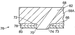
図7は、タイル58Aを通して、流出口即ち通路82を形成した後のタイル58Aの部分を示す。各流出口即ち通路82は、タイル58Aの第2表面68からタイル58Aを通って及び夫々の突出部70を通って、夫々の突出部70の第2端74の表面75まで延びている。タイル58Aは、各突出部70の周囲の第1表面66に耐熱コーティング76を有する。流出口即ち通路82は、各突出部70の第2端74の表面75から、先ず最初に夫々の突出部70を通して機械加工し、次いで、タイル58Aの主本体を通してタイル58Aの第2表面68まで機械加工することによって形成される。好ましくは、各流出口即ち通路82は、放電加工によって形成されるが、その他の適当な方法を使用してもよい。
FIG. 7 shows the portion of
各突出部70の第2端74の表面75は、タイル58Aの第1表面66から第1距離のところに配置されており、耐熱コーティング76は第1厚さを有する。第1距離は、第1厚さと等しいか或いはこれよりも大きい。各突出部70の第2端74は、夫々の流出口82を通って流れるクーラント又は空気によって冷却され、これにより、突出部70の第2端74の金属が燃えたり、ここから金属が失われたりしないようにする。
The
図9は、根部92、プラットホーム部分94、及びエーロホイル部分96を含むタービンブレード90を示す。エーロホイル部分96の外面には耐熱コーティング98が施されており、複数の流出口即ち通路100が、タービンブレード90のエーロホイル部分96を通って延びている。流出口100は、タービンブレード90のエーロホイル部分96の外面から延びる突出部に設けられており、図2乃至図8に関して燃焼室のタイルについて説明したのと同様に、耐熱コーティング98が全ての突出部を取り囲んでいる。タービンブレード90は、例えば鉄超合金、コバルト超合金、又は好ましくはニッケル超合金等の適当な金属又は合金から製造されており、例えばCMSX4、CMSX10から、鋳造により製造される。タービンブレード又はタービンベーンは、方向性凝固構成要素(指向性凝固構成要素)を製造するため、又は単結晶構成要素(単晶質構成要素)を製造するため、方向性凝固法(指向性凝固法)によって製造されてもよく、別の態様では等軸構成要素であってもよい。
FIG. 9 shows a
図4乃至図7に示すように、突出部70は一つの側部がテーパしており、角度をなした側面73を有し、これにより、流出口82を、タイル58Aの第1表面66に対して90°乃至0°の所定の角度で配置できる。突出部70の第1端72での断面積は、第2端74での断面積よりも大きい。しかしながら、流出口82をタイル58Aの第1表面66に対して90°で配置する場合には、突出部70は円筒形であってもよい。突出部70のこの他の適当な形状を使用してもよい。例えば、突出部70は全ての側部がテーパしていてもよく、突出部70の第1端72での断面積が第2端74での断面積よりも大きいように角度をなした側面73が突出部70全体に亘って延びていてもよく、例えば突出部70が円錐形とすることができ、直径が第1端72から第2端74まで減少してもよい。
As shown in FIGS. 4-7, the
例えば、流出口の直径は少なくとも0.5mmであり、最大で1mmであり、突出部の直径は少なくとも1mmであり、最大で2mmである。耐熱コーティングの厚さは最大1mmとすることができ、セラミック耐熱コーティングの厚さは最大0.5mmとすることができ、金属結合コーティングの厚さは最大0.5mmとすることができ、突出部の高さ即ち物品の表面からの第1距離は少なくとも耐熱コーティングの厚さであり、例えば最大1mmである。 For example, the diameter of the outlet is at least 0.5 mm and a maximum of 1 mm, and the diameter of the protrusion is at least 1 mm and a maximum of 2 mm. The thickness of heat resistant coating can be up to 1mm, the thickness of ceramic heat resistant coating can be up to 0.5mm, the thickness of metal bond coating can be up to 0.5mm, The first distance from the surface of the article is at least the thickness of the heat-resistant coating, for example up to 1 mm.
本発明は、耐熱コーティングを施した、第1表面及び第2表面を持つ物品を提供する。物品は、第1表面から、第1表面と第2表面から遠ざかる方向に延びる少なくとも一つの突出部を有する。突出部は、第1表面と隣接した第1端及び第1表面から遠方の第2端を有する。物品は、物品の第2表面から物品を通って、及び少なくとも一つの突出部を通って少なくとも一つの突出部の第2端まで延びる少なくとも一つの通路を有する。物品は、少なくとも一つの突出部の周囲の第1表面に耐熱コーティングを有する。 The present invention provides an article having a first surface and a second surface with a heat resistant coating. The article has at least one protrusion extending from the first surface in a direction away from the first surface and the second surface. The protrusion has a first end adjacent to the first surface and a second end remote from the first surface. The article has at least one passage extending from the second surface of the article through the article and through the at least one protrusion to the second end of the at least one protrusion. The article has a heat resistant coating on a first surface around at least one protrusion.
本発明の好ましい実施例では、複数の突出部が第1表面から第1表面から遠ざかる方向に及び第2表面から遠ざかる方向に延びる、耐熱コーティングを施した物品を提供する。各突出部は、第1表面と隣接した第1端及び第1表面から遠方の第2端を有する。物品は、物品の第2表面から延びる複数の通路を有する。各通路は、物品の第2表面から物品を通って、及び突出部の夫々を通って夫々の突出部の第2端まで延びる。物品は、各突出部の周囲の第1表面に耐熱コーティングを有する。 In a preferred embodiment of the present invention, an article with a heat resistant coating is provided in which a plurality of protrusions extend from a first surface in a direction away from the first surface and in a direction away from the second surface. Each protrusion has a first end adjacent to the first surface and a second end remote from the first surface. The article has a plurality of passages extending from the second surface of the article. Each passage extends from the second surface of the article through the article and through each of the protrusions to the second end of the respective protrusion. The article has a heat resistant coating on the first surface around each protrusion.
物品は、ガスタービンエンジン用の燃焼器タイル、タービンブレード、又はタービンベーンであってもよい。
本発明の利点は、物品の所望の穴位置の各々に実在物特徴(positive feature)即ち突出部を形成することにより、突出部から耐熱コーティングを除去でき、かくして金属製物品を所望の穴位置の各々のところで露呈するということである。これにより、突出部及び物品を通して放電加工によって穴を形成できる。これは、突出部を露呈することによって導電路が形成されるためである。本発明は、耐熱コーティングの層間剥離が生じず、そして流出口が塞がれない丈夫な耐熱コーティングを備えた物品を提供する。製造上有利な対費用効果に優れた方法で物品を製造できる。
The article may be a combustor tile, turbine blade, or turbine vane for a gas turbine engine.
An advantage of the present invention is that by forming a positive feature or protrusion at each desired hole location in the article, the heat resistant coating can be removed from the protrusion, thus allowing the metal article to be placed in the desired hole position. It is exposed at each place. Thereby, a hole can be formed by electrical discharge machining through the protrusion and the article. This is because a conductive path is formed by exposing the protruding portion. The present invention provides an article with a durable heat resistant coating that does not delaminate the heat resistant coating and does not block the outlet. Articles can be manufactured in a cost-effective manner advantageous for manufacturing.
本発明の別の方法では、突出部の第2端が燃える問題がある場合、突出部の寸法、例えば直径を調節し、小さくすることが決定してもよい。放電加工プロセスにより流出口を形成し、突出部の少なくとも一部を機械加工によって除去し、突出部の高さを小さくし、燃えるという問題をなくすことができる。例えば突出部の第2端を第1表面から、耐熱コーティングの第1厚さよりも小さい第1距離のところに配置するようにしてもよい。 In another method of the present invention, if there is a problem that the second end of the protrusion burns, it may be decided to adjust and reduce the size of the protrusion, for example, the diameter. It is possible to eliminate the problem of forming an outlet by an electric discharge machining process, removing at least a part of the protruding portion by machining, reducing the height of the protruding portion, and burning. For example, the second end of the protruding portion may be disposed at a first distance smaller than the first thickness of the heat resistant coating from the first surface.
42 環状燃焼室
44 環状半径方向内壁
46 環状半径方向外壁
48 上流端壁
50 ケーシング
52 燃料インジェクタ穴
54 燃料インジェクタ
55 穴
56 半径方向内壁
57 チャンバ
58 半径方向外壁
59 流出口
58A、58B、60A、60B タイル
60 半径方向内壁
61 穴
62 半径方向外壁
63 チャンバ
64 スタッド
65 流出口
66 第1表面
68 第2表面
70 突出部
72 第1端
74 第2端
42
Claims (20)
前記物品は、第1表面及び第2表面を有し、
前記物品は、前記第1表面から、前記第1表面から遠ざかる方向に及び前記第2表面から遠ざかる方向に延びる少なくとも一つの突出部を有し、
前記突出部は、前記第1表面と隣接した第1端及び前記第1表面から遠方の第2端を有し、
前記少なくとも一つの突出部の前記第2端は表面を有し、
前記物品は、前記物品の前記第2表面から前記物品を通って、前記少なくとも一つの突出部を通って前記少なくとも一つの突出部の前記第2端の前記表面まで延びる少なくとも一つの通路を有し、
前記少なくとも一つの通路は、流出冷却口であり、
前記物品は、前記少なくとも一つの突出部の周囲の前記第1表面上に耐熱コーティングを有する、耐熱コーティングを施した物品。 In articles with heat-resistant coating,
The article has a first surface and a second surface;
The article has at least one protrusion extending from the first surface in a direction away from the first surface and in a direction away from the second surface;
The protrusion has a first end adjacent to the first surface and a second end remote from the first surface;
The second end of the at least one protrusion has a surface;
The article has at least one passage extending from the second surface of the article through the article, through the at least one protrusion to the surface of the second end of the at least one protrusion. ,
The at least one passage is an outlet cooling port;
The article having a heat-resistant coating having a heat-resistant coating on the first surface around the at least one protrusion.
前記物品は、前記第1表面から、前記第1表面から遠ざかる方向に及び前記第2表面から遠ざかる方向に延びる複数の突出部を有し、
各突出部は、前記第1表面と隣接した第1端及び前記第1表面から遠方の第2端を有し、
各突出部の前記第2端は表面を有し、
前記物品は、前記物品の前記第2表面から延びる複数の通路を有し、
各通路は、前記物品の前記第2表面から前記物品を通って及び前記突出部の夫々一つを通って前記夫々の突出部の前記第2端の前記表面まで延び、
前記物品は、各突出部の周囲の前記第1表面上に耐熱コーティングを有する、耐熱コーティングを施した物品。 In the article provided with the heat-resistant coating according to claim 1,
The article has a plurality of protrusions extending from the first surface in a direction away from the first surface and in a direction away from the second surface,
Each protrusion has a first end adjacent to the first surface and a second end remote from the first surface;
The second end of each protrusion has a surface;
The article has a plurality of passages extending from the second surface of the article;
Each passage extends from the second surface of the article through the article and through each one of the protrusions to the surface of the second end of the respective protrusions;
The article has a heat resistant coating having a heat resistant coating on the first surface around each protrusion.
前記少なくとも一つの突出部の前記第2端は、前記物品の前記第1表面から第1距離のところに配置されており、
前記耐熱コーティングは第1厚さを有し、
前記第1距離は、少なくとも前記第1厚さと等しい、耐熱コーティングを施した物品。 In the article provided with the heat-resistant coating according to claim 1 or 2,
The second end of the at least one protrusion is disposed at a first distance from the first surface of the article;
The heat resistant coating has a first thickness;
The first distance is equal to at least the first thickness, and the article is provided with a heat resistant coating.
前記耐熱コーティングは、前記物品の前記第1表面上に設けられた金属結合コーティングと、前記金属結合コーティング上に設けられたセラミック耐熱コーティングとを備えた、耐熱コーティングを施した物品。 In the article provided with the heat-resistant coating according to claim 1, 2, or 3,
The heat-resistant coating is an article provided with a heat-resistant coating, comprising a metal bond coating provided on the first surface of the article and a ceramic heat-resistant coating provided on the metal bond coating.
前記金属結合コーティングは、MCrAlYコーティング及びアルミナイドコーティングからなる群から選択され、ここでMは、Ni、Co、及びFeのうちの一つ又はそれ以上である、耐熱コーティングを施した物品。 In the article provided with the heat-resistant coating according to claim 4,
The metal bonded coating is selected from the group consisting of MCrAlY coating and aluminide coating, wherein M is one or more of Ni, Co, and Fe.
前記セラミック耐熱コーティングは、安定化ジルコニア及びイットリア安定化ジルコニアからなる群から選択される、耐熱コーティングを施した物品。 In the article provided with the heat-resistant coating according to claim 4,
The ceramic heat-resistant coating is an article having a heat-resistant coating selected from the group consisting of stabilized zirconia and yttria stabilized zirconia.
前記物品は、燃焼器タイル、タービンブレード、又はタービンベーンからなる群から選択される、耐熱コーティングを施した物品。 In the article provided with the heat-resistant coating according to any one of claims 1 to 6,
The article is a heat-resistant coated article selected from the group consisting of combustor tiles, turbine blades, or turbine vanes.
a)第1表面及び第2表面を有する物品であって、前記第1表面から、前記第1表面から遠ざかる方向に及び前記第2表面から遠ざかる方向に延びる少なくとも一つの突出部を有し、前記少なくとも一つの突出部は、前記第1表面と隣接した第1端及び前記第1表面から遠方の第2端を有し、前記少なくとも一つの突出部の前記第2端は表面を有する、物品を形成する工程と、
b)耐熱コーティングを、前記少なくとも一つの突出部の周囲の前記物品の前記第1表面に、及び前記少なくとも一つの突出部の前記第2端の表面に付着する工程と、
c)前記少なくとも一つの突出部の前記第2端から前記耐熱コーティングを除去する工程と、
d)前記物品の前記第2表面から前記物品を通って及び前記少なくとも一つの突出部を通って前記少なくとも一つの突出部の前記第2端の前記表面まで延びる少なくとも一つの通路を前記少なくとも一つの突出部を通して形成する工程とを有し、前記少なくとも一つの通路は流出冷却口である、方法。 In the method of manufacturing an article having a heat-resistant coating,
a) an article having a first surface and a second surface, the article having at least one protrusion extending from the first surface in a direction away from the first surface and in a direction away from the second surface; The at least one protrusion has a first end adjacent to the first surface and a second end remote from the first surface, and the second end of the at least one protrusion has a surface. Forming, and
b) applying a heat resistant coating to the first surface of the article around the at least one protrusion and to the surface of the second end of the at least one protrusion;
c) removing the heat resistant coating from the second end of the at least one protrusion;
d) at least one passage extending from the second surface of the article through the article and through the at least one protrusion to the surface of the second end of the at least one protrusion. Forming through protrusions, wherein the at least one passage is an outlet cooling port.
前記工程a)は、前記第1表面から、前記第1表面から遠ざかる方向及び前記第2表面から遠ざかる方向に延びる複数の突出部を持つ物品であって、各突出部は、前記第1表面と隣接した第1端及び前記第1表面から遠方の第2端を有し、各突出部の前記第2端は表面を有する、物品を形成する工程を含み、
前記工程b)は、前記突出部の各々の周囲の前記物品の前記第1表面に、及び前記突出部の各々の前記第2端の前記表面に耐熱コーティングを付着する工程を含み、
前記工程c)は、前記突出部の各々の前記第2端から前記耐熱コーティングを除去する工程を含み、
前記工程d)は、前記物品の前記第2表面から前記物品を通って、及び夫々の突出部を通って前記夫々の突出部の前記第2端の表面まで延びる通路を、各突出部を通して形成する工程を含む、方法。 The method of claim 8, wherein
The step a) is an article having a plurality of protrusions extending from the first surface in a direction away from the first surface and in a direction away from the second surface, and each protrusion includes the first surface and the first surface. Forming an article having an adjacent first end and a second end remote from the first surface, wherein the second end of each protrusion has a surface;
The step b) includes applying a heat resistant coating to the first surface of the article around each of the protrusions and to the surface of the second end of each of the protrusions;
Step c) includes removing the heat resistant coating from the second end of each of the protrusions;
Step d) forms a passage through each projection from the second surface of the article through the article and through each projection to the surface of the second end of each projection. A method comprising the steps of:
前記少なくとも一つの突出部の前記第2端は、前記物品の前記第1表面から第1距離のところに配置されており、前記耐熱コーティングは第1厚さを有し、前記第1距離は、少なくとも前記第1厚さと等しい、方法。 The method according to claim 8 or 9, wherein
The second end of the at least one protrusion is disposed at a first distance from the first surface of the article, the heat resistant coating has a first thickness, and the first distance is: A method that is at least equal to the first thickness.
前記工程b)は、前記物品の前記第1表面に金属結合コーティングを付着する工程と、前記金属結合コーティングにセラミック耐熱コーティングを付着する工程とを含む、方法。 A method according to claim 8, 9 or 10,
The step b) comprises the steps of depositing a metal bond coating on the first surface of the article and depositing a ceramic heat resistant coating on the metal bond coating.
前記金属結合コーティングは、MCrAlYコーティング及びアルミナイドコーティングからなる群から選択され、ここでMは、Ni、Co、及びFeのうちの一つ又はそれ以上である、方法。 The method of claim 11, wherein
The method wherein the metal bond coating is selected from the group consisting of MCrAlY coating and aluminide coating, wherein M is one or more of Ni, Co, and Fe.
前記セラミック耐熱コーティングは、安定化ジルコニア及びイットリア安定化ジルコニアからなる群から選択される、方法。 The method according to claim 11 or 12,
The ceramic heat resistant coating is selected from the group consisting of stabilized zirconia and yttria stabilized zirconia.
前記物品は、燃焼器タイル、タービンブレード、又はタービンベーンからなる群から選択される、方法。 14. A method according to any one of claims 8 to 13,
The method wherein the article is selected from the group consisting of combustor tiles, turbine blades, or turbine vanes.
前記工程a)は、鋳造及び直接レーザー蒸着からなる群から選択された方法で、前記物品と、前記少なくとも一つの突出部とを形成する工程を含む、方法。 15. A method as claimed in any one of claims 8 to 14,
The step a) includes forming the article and the at least one protrusion in a method selected from the group consisting of casting and direct laser deposition.
前記工程c)は、機械加工工程を含む、方法。 A method according to any one of claims 8 to 15,
Said step c) comprises a machining step.
前記工程d)は、放電加工工程を含む、方法。 A method according to any one of claims 8 to 16,
The step d) includes an electric discharge machining step.
前記工程b)は、プラズマ溶射、溶射、及びHVOFからなる群から選択された方法により、前記金属結合コーティングを付着する工程を含む、方法。 The method of claim 11, wherein
The step b) includes depositing the metal bond coating by a method selected from the group consisting of plasma spraying, thermal spraying, and HVOF.
前記工程b)は、プラズマ溶射、溶射、及びHVOFからなる群から選択された方法により、前記セラミック耐熱コーティングを付着する工程を含む、方法。 The method of claim 11, wherein
The step b) includes depositing the ceramic heat resistant coating by a method selected from the group consisting of plasma spraying, thermal spraying, and HVOF.
前記工程d)は、前記第1距離が前記第1厚さよりも小さくなるように前記突出部の少なくとも一部を除去する工程を含む、方法。 The method of claim 10, wherein
The step d) includes the step of removing at least a part of the protrusion so that the first distance is smaller than the first thickness.
Applications Claiming Priority (2)
| Application Number | Priority Date | Filing Date | Title |
|---|---|---|---|
| GB1205011.8 | 2012-03-22 | ||
| GBGB1205011.8A GB201205011D0 (en) | 2012-03-22 | 2012-03-22 | A thermal barrier coated article and a method of manufacturing a thermal barrier coated article |
Publications (1)
| Publication Number | Publication Date |
|---|---|
| JP2013194324A true JP2013194324A (en) | 2013-09-30 |
Family
ID=46086910
Family Applications (1)
| Application Number | Title | Priority Date | Filing Date |
|---|---|---|---|
| JP2013058047A Pending JP2013194324A (en) | 2012-03-22 | 2013-03-21 | Thermal barrier coated article, and method of manufacturing the same |
Country Status (4)
| Country | Link |
|---|---|
| US (1) | US20130251941A1 (en) |
| EP (1) | EP2641992A3 (en) |
| JP (1) | JP2013194324A (en) |
| GB (1) | GB201205011D0 (en) |
Cited By (1)
| Publication number | Priority date | Publication date | Assignee | Title |
|---|---|---|---|---|
| JP2014080973A (en) * | 2012-10-15 | 2014-05-08 | General Electric Co <Ge> | Hot gas path component cooling film hole plateau |
Families Citing this family (6)
| Publication number | Priority date | Publication date | Assignee | Title |
|---|---|---|---|---|
| GB201205020D0 (en) * | 2012-03-22 | 2012-05-09 | Rolls Royce Plc | A method of manufacturing a thermal barrier coated article |
| DE102013222863A1 (en) * | 2013-11-11 | 2015-05-13 | Rolls-Royce Deutschland Ltd & Co Kg | Gas turbine combustor and method for its production |
| DE102014204476A1 (en) * | 2014-03-11 | 2015-10-01 | Rolls-Royce Deutschland Ltd & Co Kg | Combustion chamber of a gas turbine |
| DE102014204481A1 (en) | 2014-03-11 | 2015-09-17 | Rolls-Royce Deutschland Ltd & Co Kg | Combustion chamber of a gas turbine |
| GB201419327D0 (en) | 2014-10-30 | 2014-12-17 | Rolls Royce Plc | A cooled component |
| EP3342979B1 (en) * | 2016-12-30 | 2020-06-17 | Ansaldo Energia Switzerland AG | Gas turbine comprising cooled rotor disks |
Family Cites Families (6)
| Publication number | Priority date | Publication date | Assignee | Title |
|---|---|---|---|---|
| US4743462A (en) * | 1986-07-14 | 1988-05-10 | United Technologies Corporation | Method for preventing closure of cooling holes in hollow, air cooled turbine engine components during application of a plasma spray coating |
| US5902647A (en) * | 1996-12-03 | 1999-05-11 | General Electric Company | Method for protecting passage holes in a metal-based substrate from becoming obstructed, and related compositions |
| US6573474B1 (en) * | 2000-10-18 | 2003-06-03 | Chromalloy Gas Turbine Corporation | Process for drilling holes through a thermal barrier coating |
| GB0610578D0 (en) * | 2006-05-27 | 2006-07-05 | Rolls Royce Plc | Method of removing deposits |
| US8661826B2 (en) * | 2008-07-17 | 2014-03-04 | Rolls-Royce Plc | Combustion apparatus |
| US20120164376A1 (en) * | 2010-12-23 | 2012-06-28 | General Electric Company | Method of modifying a substrate for passage hole formation therein, and related articles |
-
2012
- 2012-03-22 GB GBGB1205011.8A patent/GB201205011D0/en not_active Ceased
-
2013
- 2013-03-13 US US13/799,501 patent/US20130251941A1/en not_active Abandoned
- 2013-03-13 EP EP13158929.3A patent/EP2641992A3/en not_active Withdrawn
- 2013-03-21 JP JP2013058047A patent/JP2013194324A/en active Pending
Cited By (1)
| Publication number | Priority date | Publication date | Assignee | Title |
|---|---|---|---|---|
| JP2014080973A (en) * | 2012-10-15 | 2014-05-08 | General Electric Co <Ge> | Hot gas path component cooling film hole plateau |
Also Published As
| Publication number | Publication date |
|---|---|
| US20130251941A1 (en) | 2013-09-26 |
| EP2641992A3 (en) | 2014-05-14 |
| GB201205011D0 (en) | 2012-05-09 |
| EP2641992A2 (en) | 2013-09-25 |
Similar Documents
| Publication | Publication Date | Title |
|---|---|---|
| JP2013216974A (en) | Thermal barrier coated article and manufacturing method therefor | |
| JP2013194324A (en) | Thermal barrier coated article, and method of manufacturing the same | |
| CN106246237B (en) | Hot gas path component with near wall cooling features | |
| EP1245787B1 (en) | Cooling system for a coated turbine blade tip | |
| JP6981724B2 (en) | High temperature gas path component cooling system with particle collection chamber | |
| US7402335B2 (en) | Layer structure and method for producing such a layer structure | |
| US8661826B2 (en) | Combustion apparatus | |
| EP1245786B1 (en) | Turbine airfoil trailing edge with micro cooling channels | |
| US6329015B1 (en) | Method for forming shaped holes | |
| EP3106617B1 (en) | Hot gas path component having cast-in features for near wall cooling | |
| US20130045106A1 (en) | Angled trench diffuser | |
| JP2017002908A (en) | Hot gas path component with trailing edge having near wall cooling features | |
| JP2009542455A (en) | Layered insulation layer and component with high porosity | |
| JP2008101607A (en) | Vane cluster provided with coated metallic substrate, method for manufacturing vane cluster, and method for designing vane cluster | |
| JP2015017609A (en) | Turbine component and methods of assembling the same | |
| JP2012052535A (en) | Component with conformal curved film hole and method of manufacturing the same | |
| JP2007170398A (en) | Method for coating gas turbine component, and turbine blade | |
| US20140102684A1 (en) | Hot gas path component cooling film hole plateau | |
| CN110325666A (en) | The coating of aerofoil profile for gas-turbine unit and the method for applying coating | |
| US9862002B2 (en) | Process for producing a layer system | |
| US20190169730A1 (en) | Methods of forming a porous thermal barrier coating | |
| JP2022506999A (en) | Additional support with integrated film cooling | |
| GB2461897A (en) | Shield for preventing coating build up | |
| US11821337B1 (en) | Internal aluminide coating for vanes and blades and method of manufacture | |
| JP2017122440A (en) | Solution heat treatment method for manufacturing metallic component of turbo machine |