JP2013193193A - Cutting device - Google Patents

Cutting device Download PDF

Info

Publication number
JP2013193193A
JP2013193193A JP2012065488A JP2012065488A JP2013193193A JP 2013193193 A JP2013193193 A JP 2013193193A JP 2012065488 A JP2012065488 A JP 2012065488A JP 2012065488 A JP2012065488 A JP 2012065488A JP 2013193193 A JP2013193193 A JP 2013193193A
Authority
JP
Japan
Prior art keywords
cutter
cutting
workpiece
edge
pressing
Prior art date
Legal status (The legal status is an assumption and is not a legal conclusion. Google has not performed a legal analysis and makes no representation as to the accuracy of the status listed.)
Pending
Application number
JP2012065488A
Other languages
Japanese (ja)
Inventor
Michihiro Iida
充弘 飯田
Tomoyasu Niizeki
友康 新関
Current Assignee (The listed assignees may be inaccurate. Google has not performed a legal analysis and makes no representation or warranty as to the accuracy of the list.)
Brother Industries Ltd
Original Assignee
Brother Industries Ltd
Priority date (The priority date is an assumption and is not a legal conclusion. Google has not performed a legal analysis and makes no representation as to the accuracy of the date listed.)
Filing date
Publication date
Application filed by Brother Industries Ltd filed Critical Brother Industries Ltd
Priority to JP2012065488A priority Critical patent/JP2013193193A/en
Priority to US13/847,933 priority patent/US20130276607A1/en
Publication of JP2013193193A publication Critical patent/JP2013193193A/en
Pending legal-status Critical Current

Links

Images

Classifications

    • BPERFORMING OPERATIONS; TRANSPORTING
    • B26HAND CUTTING TOOLS; CUTTING; SEVERING
    • B26DCUTTING; DETAILS COMMON TO MACHINES FOR PERFORATING, PUNCHING, CUTTING-OUT, STAMPING-OUT OR SEVERING
    • B26D7/00Details of apparatus for cutting, cutting-out, stamping-out, punching, perforating, or severing by means other than cutting
    • B26D7/01Means for holding or positioning work
    • B26D7/015Means for holding or positioning work for sheet material or piles of sheets
    • BPERFORMING OPERATIONS; TRANSPORTING
    • B26HAND CUTTING TOOLS; CUTTING; SEVERING
    • B26DCUTTING; DETAILS COMMON TO MACHINES FOR PERFORATING, PUNCHING, CUTTING-OUT, STAMPING-OUT OR SEVERING
    • B26D7/00Details of apparatus for cutting, cutting-out, stamping-out, punching, perforating, or severing by means other than cutting
    • B26D7/01Means for holding or positioning work
    • B26D7/02Means for holding or positioning work with clamping means
    • B26D7/025Means for holding or positioning work with clamping means acting upon planar surfaces
    • BPERFORMING OPERATIONS; TRANSPORTING
    • B26HAND CUTTING TOOLS; CUTTING; SEVERING
    • B26FPERFORATING; PUNCHING; CUTTING-OUT; STAMPING-OUT; SEVERING BY MEANS OTHER THAN CUTTING
    • B26F1/00Perforating; Punching; Cutting-out; Stamping-out; Apparatus therefor
    • B26F1/38Cutting-out; Stamping-out
    • B26F1/3806Cutting-out; Stamping-out wherein relative movements of tool head and work during cutting have a component tangential to the work surface
    • BPERFORMING OPERATIONS; TRANSPORTING
    • B26HAND CUTTING TOOLS; CUTTING; SEVERING
    • B26FPERFORATING; PUNCHING; CUTTING-OUT; STAMPING-OUT; SEVERING BY MEANS OTHER THAN CUTTING
    • B26F1/00Perforating; Punching; Cutting-out; Stamping-out; Apparatus therefor
    • B26F1/38Cutting-out; Stamping-out
    • B26F2001/388Cutting-out; Stamping-out controlling the blade orientation along the cutting path
    • YGENERAL TAGGING OF NEW TECHNOLOGICAL DEVELOPMENTS; GENERAL TAGGING OF CROSS-SECTIONAL TECHNOLOGIES SPANNING OVER SEVERAL SECTIONS OF THE IPC; TECHNICAL SUBJECTS COVERED BY FORMER USPC CROSS-REFERENCE ART COLLECTIONS [XRACs] AND DIGESTS
    • Y10TECHNICAL SUBJECTS COVERED BY FORMER USPC
    • Y10TTECHNICAL SUBJECTS COVERED BY FORMER US CLASSIFICATION
    • Y10T83/00Cutting
    • Y10T83/566Interrelated tool actuating means and means to actuate work immobilizer

Landscapes

  • Life Sciences & Earth Sciences (AREA)
  • Forests & Forestry (AREA)
  • Engineering & Computer Science (AREA)
  • Mechanical Engineering (AREA)
  • Control Of Cutting Processes (AREA)
  • Details Of Cutting Devices (AREA)

Abstract

PROBLEM TO BE SOLVED: To provide a cutting device capable of suitably pressing a body to be cut by arranging a press member for the body to be cut as close to a cutter as possible.SOLUTION: A cutting means of a cutting device includes a cutter 4 having a cutting edge 4b at a tip, a support device 46 supporting the cutter 4 so that the direction of the cutting edge 4b can be changed, and a pressing device 47 which has a pressing member 61 for pressing a body 6 to be cut near the cutting edge 4b of the cutter 4, and maintains a position where the pressing member 61 presses the body to be cut near the cutting edge 4b in conjunction with the cutting edge 4b accompanied by a change of the direction of the cutting edge 4b of the cutter 4 when the cutting means and body 6 to be cut move relatively.

Description

本発明は、切断手段と被切断物とを相対的に移動させることにより、前記被切断物から所望の模様を切断する切断装置に関する。   The present invention relates to a cutting apparatus that cuts a desired pattern from an object to be cut by relatively moving a cutting means and the object to be cut.

従来より、例えば紙等のシートを自動的に切断するカッティングプロッタが知られている。前記カッティングプロッタは、紙等のシートを、駆動機構のローラで上下方向から挟んで第1方向へ移動させると共に、カッタを有するキャリッジを前記第1方向と直交する第2方向へ移動させて前記シートを切断する。
前記カッタは、上下方向に延びる棒状(軸状)のカッタ軸と、このカッタ軸の下端に形成された刃部からなる。前記カッタは、キャリッジに対してカッタ軸の軸線の回りに回動自在に取付けられている。また、カッタの刃部の先端(下端)、つまりカッタの切先は、カッタ軸に対して偏心した位置にある。このため、カッタとシートとの相対移動によりシートを切断する時、カッタの切先がシートから抵抗力(反力)を受けることで、刃先の向きが、シートに対して相対移動する方向に応じて自動的に変更される。
2. Description of the Related Art Conventionally, a cutting plotter that automatically cuts a sheet such as paper is known. The cutting plotter moves a sheet of paper or the like in a first direction with a roller of a driving mechanism sandwiched from above and below, and moves a carriage having a cutter in a second direction orthogonal to the first direction. Disconnect.
The cutter includes a rod-shaped (shaft-shaped) cutter shaft extending in the vertical direction and a blade portion formed at the lower end of the cutter shaft. The cutter is attached to the carriage so as to be rotatable around the axis of the cutter shaft. Further, the tip (lower end) of the cutter blade, that is, the cutting edge of the cutter is at a position eccentric with respect to the cutter shaft. For this reason, when cutting the sheet by relative movement between the cutter and the sheet, the cutting edge of the cutter receives a resistance force (reaction force) from the sheet, so that the direction of the blade edge corresponds to the direction of relative movement with respect to the sheet Will be changed automatically.

この種のカッティングプロッタでは、前記シートを上方から押える付勢板を設け、この付勢板で、シートの浮きを防止するようにしたものが供されている(例えば特許文献1参照)。付勢板は、カッタの両側方に配置される一対の押圧部が夫々の基端側で繋がる平面視略U字状をなし、それら押圧部でシートを押圧するよう構成されている。   In this type of cutting plotter, an urging plate that presses the sheet from above is provided, and the urging plate prevents the sheet from floating (see, for example, Patent Document 1). The urging plate has a substantially U shape in a plan view in which a pair of pressing portions arranged on both sides of the cutter are connected to each proximal end side, and is configured to press the sheet with these pressing portions.

特開平7−251599号公報Japanese Patent Laid-Open No. 7-251599

しかしながら、従来の付勢板の押圧部は、カッタの刃部から少し離間した位置でシートを押圧するため、切断後のシートの浮き或は捲れを確実に防止することは困難であった。特に、シートの切断ラインの角部(コーナー部)を切断する際、カッタの刃先が回動して向きを変えることに伴い、付勢板でシートを押えた状態でも、シートの捲れが発生する虞があった。
この問題を解消するには、付勢板の押圧部をカッタの刃先に極力近接させて配置することが考えられる。しかしながら、カッタの刃先はカッタ軸の軸線の回りに回動するので、付勢板の押圧部とカッタの刃先(刃先側面を含む)との衝突を回避する為に、付勢板の押圧部とカッタの刃先との間には適当な隙間が必要であり、付勢板の押圧部とカッタの刃先とを極力近接させることは困難であった。
However, since the pressing portion of the conventional urging plate presses the sheet at a position slightly separated from the blade portion of the cutter, it has been difficult to reliably prevent the sheet from being lifted or twisted after cutting. In particular, when cutting the corner portion (corner portion) of the sheet cutting line, the blade edge of the cutter rotates and changes its direction, so that the sheet curls even when the sheet is pressed by the urging plate. There was a fear.
In order to solve this problem, it is conceivable to place the pressing portion of the urging plate as close as possible to the blade edge of the cutter. However, since the cutting edge of the cutter rotates about the axis of the cutter shaft, in order to avoid collision between the pressing portion of the urging plate and the cutting edge (including the side surface of the cutting edge) of the urging plate, An appropriate gap is required between the cutter blade edge and it is difficult to bring the pressing portion of the biasing plate and the cutter blade edge as close as possible.

本発明は上記事情に鑑みてなされたものであり、その目的は、被切断物の押え部材を極力カッタに近接させて配置し、被切断物を確実に押えることができる切断装置を提供することである。   The present invention has been made in view of the above circumstances, and an object of the present invention is to provide a cutting device that can place a workpiece to be cut as close as possible to the cutter and reliably hold the workpiece. It is.

上記した目的を達成するために、本発明の請求項1の切断装置は、切断手段と被切断物とを相対的に移動させることにより、前記被切断物から所望の模様を切断するものであり、前記切断手段は、先端部に刃先を有するカッタと、前記カッタを刃先の向きの変更が可能に支持する支持手段と、前記カッタの刃先近傍で前記被切断物を押える押え部材を有し、前記切断手段と前記被切断物との相対移動の際に、前記カッタの刃先の向きが変更されることに伴い、前記押え部材が当該刃先と連動して前記刃先近傍で押える位置を維持するように構成された押え手段と、を備えることを特徴とする。   In order to achieve the above object, the cutting apparatus according to claim 1 of the present invention cuts a desired pattern from the object to be cut by relatively moving the cutting means and the object to be cut. The cutting means includes a cutter having a cutting edge at a tip, a supporting means for supporting the cutter so that the orientation of the cutting edge can be changed, and a pressing member for pressing the workpiece in the vicinity of the cutting edge of the cutter, When the relative movement between the cutting means and the object to be cut, the presser member maintains the pressing position in the vicinity of the cutting edge in conjunction with the cutting edge as the direction of the cutting edge of the cutter is changed. And presser means configured as described above.

上記構成によれば、押え部材は、切断時にカッタの刃先の向きが変わっても、カッタの刃先との連動により、刃先(刃先側面を含む)に衝突することなく、刃先近傍で被切断物を押える位置が維持される。従って、押え部材を刃先に極力近接させた配置構成とすることができる。このため、カッタで被切断物を切断する際に、押え部材によって、常に刃先近傍で被切断物を押えることができ、被切断物の浮きや捲れを防止して正確に切断することができる。   According to the above configuration, even if the direction of the cutter blade edge changes during cutting, the presser member does not collide with the blade edge (including the side surface of the blade edge) and interlocks with the blade edge of the cutter without cutting the object to be cut near the blade edge. The pressing position is maintained. Therefore, it can be set as the arrangement configuration which made the presser member close to the blade edge as much as possible. For this reason, when cutting the object to be cut with the cutter, the object to be cut can always be pressed in the vicinity of the cutting edge by the pressing member, and the object can be cut accurately while preventing the object from being lifted or twisted.

請求項2の切断装置は、切断手段と被切断物とを相対的に移動させることにより、前記被切断物から所望の模様を切断するものであり、前記切断手段は、一方向に延びる基部の中心軸に対して偏心した刃先を先端部に有するカッタと、前記カッタを前記中心軸の回りに回動可能に支持する支持手段と、前記カッタの刃先を囲うように形成され前記被切断物を押える押え部材を有し、前記切断手段と前記被切断物との相対移動の際に、前記カッタが前記中心軸の回りに回動して刃先の向きが変更されることに伴い、前記押え部材が当該刃先と連動して回動するように構成された押え手段と、を備えることを特徴とする。   The cutting device according to claim 2 is for cutting a desired pattern from the object to be cut by relatively moving the cutting means and the object to be cut, and the cutting means has a base portion extending in one direction. A cutter having a cutting edge eccentric with respect to the central axis at a tip portion; support means for rotatably supporting the cutter around the central axis; and the object to be cut formed to surround the cutting edge of the cutter. A presser member, and the cutter member is rotated around the central axis and the direction of the blade edge is changed when the cutting means and the workpiece are moved relative to each other. And presser means configured to rotate in conjunction with the cutting edge.

上記構成によれば、押え部材は、切断時にカッタの刃先の向きが変わっても、カッタの刃先と連動して中心軸の回りに回動するため、刃先(刃先側面を含む)に衝突することなく、刃先を囲う位置で被切断物を押えた状態が維持される。従って、押え部材を刃先に極力近接させた配置構成とすることができる。このため、カッタで被切断物を切断する際に、押え部材によって、常に刃先近傍で被切断物を押えることができ、被切断物の浮きや捲れを防止して正確に切断することができる。   According to the above configuration, the presser member collides with the cutting edge (including the side surface of the cutting edge) because it rotates around the central axis in conjunction with the cutting edge of the cutter even if the orientation of the cutting edge of the cutter changes during cutting. The state in which the object to be cut is pressed at the position surrounding the blade edge is maintained. Therefore, it can be set as the arrangement configuration which made the presser member close to the blade edge as much as possible. For this reason, when cutting the object to be cut with the cutter, the object to be cut can always be pressed in the vicinity of the cutting edge by the pressing member, and the object can be cut accurately while preventing the object from being lifted or twisted.

請求項3の切断装置は、請求項1または2の発明において、前記押え手段は、前記押え部材を前記被切断物側へ付勢する付勢部材を備えることを特徴とする。
請求項4の切断装置は、請求項3の発明において、前記押え部材は、前記付勢部材を介して前記支持手段に連結されていることを特徴とする。
According to a third aspect of the present invention, in the invention of the first or second aspect, the pressing means includes a biasing member that biases the pressing member toward the workpiece.
According to a fourth aspect of the present invention, in the invention of the third aspect, the pressing member is connected to the support means via the biasing member.

請求項5の切断装置は、請求項1から4の何れかの発明において、前記押え部材は、前記被切断物に接触する接触部と、前記接触部を前記カッタが延びる方向に貫通する貫通孔とを備え、前記貫通孔内で前記カッタの刃先側との係合が可能に構成されていることを特徴とする。   According to a fifth aspect of the present invention, there is provided the cutting device according to any one of the first to fourth aspects, wherein the pressing member includes a contact portion that contacts the workpiece and a through hole that penetrates the contact portion in a direction in which the cutter extends. And is configured to be able to engage with the cutting edge side of the cutter in the through hole.

請求項6の切断装置は、請求項5の発明において、前記カッタは、前記刃先の先端ほど細くなる先細状に形成され、前記貫通孔は、前記カッタの刃先側における前記カッタが延びる方向に対する垂直な断面と略相似形をなすことを特徴とする。
請求項7の切断装置は、請求項6の発明において、前記押え部材は、前記カッタが延びる方向とは垂直な方向であって、前記刃先と前記貫通孔とが略隙間無く接触する方向に移動可能に前記付勢部材に保持されていることを特徴とする。
According to a sixth aspect of the present invention, in the invention of the fifth aspect, the cutter is formed in a taper shape that becomes thinner toward the tip of the blade edge, and the through hole is perpendicular to the direction in which the cutter extends on the blade edge side of the cutter. It is characterized by having a substantially similar shape to a simple cross section.
According to a seventh aspect of the present invention, in the invention of the sixth aspect, the pressing member moves in a direction perpendicular to a direction in which the cutter extends, and in which the cutting edge and the through-hole are in contact with each other without a substantial gap. It is held by the biasing member as possible.

請求項1の切断装置によれば、押え部材は、切断時にカッタの刃先の向きが変わっても、カッタの刃先との連動により、刃先(刃先側面を含む)に衝突することなく、刃先近傍で被切断物を押える位置が維持される。従って、押え部材を刃先に極力近接させた配置構成とすることができる。このため、カッタで被切断物を切断する際に、押え部材によって、常に刃先近傍を押えることができ、被切断物の浮きや捲れを防止して正確に切断することができる。   According to the cutting device of claim 1, even if the orientation of the cutting edge of the cutter changes during cutting, the holding member does not collide with the cutting edge (including the side surface of the cutting edge) by being interlocked with the cutting edge of the cutter. The position where the workpiece is pressed is maintained. Therefore, it can be set as the arrangement configuration which made the presser member close to the blade edge as much as possible. For this reason, when the object to be cut is cut with the cutter, the vicinity of the cutting edge can always be held by the holding member, and the object can be cut accurately while preventing the object to be cut from rising or twisting.

請求項2の切断装置によれば、押え部材は、切断時にカッタの刃先の向きが変わっても、カッタの刃先と連動して中心軸の回りに回動するため、刃先(刃先側面を含む)に衝突することなく、刃先を囲う位置で被切断物を押えた状態が維持される。従って、押え部材を刃先に極力近接させた配置構成とすることができる。このため、カッタで被切断物を切断する際に、押え部材によって、常に刃先近傍で被切断物を押えることができ、被切断物の浮きや捲れを防止して正確に切断することができる。   According to the cutting device of claim 2, even if the orientation of the cutter blade edge changes during cutting, the presser member rotates around the central axis in conjunction with the cutter blade edge. The state in which the object to be cut is pressed at the position surrounding the blade edge is maintained without collision. Therefore, it can be set as the arrangement configuration which made the presser member close to the blade edge as much as possible. For this reason, when cutting the object to be cut with the cutter, the object to be cut can always be pressed in the vicinity of the cutting edge by the pressing member, and the object can be cut accurately while preventing the object from being lifted or twisted.

請求項3の切断装置によれば、請求項1または2に記載の発明の効果に加え、付勢部材の付勢力により、押え部材で被切断物を押圧することができる。従って、切断時における被切断物の浮きや捲れを、より確実に防止することができる。
請求項4の切断装置によれば、請求項3に記載の発明の効果に加え、付勢部材を利用して押え部材を支持手段に連結することができ、押え部材の支持構造を簡単化できる。
According to the cutting device of claim 3, in addition to the effect of the invention of claim 1 or 2, the object to be cut can be pressed by the pressing member by the urging force of the urging member. Accordingly, it is possible to more reliably prevent the workpiece from being lifted or twisted during cutting.
According to the cutting device of claim 4, in addition to the effect of the invention of claim 3, the pressing member can be connected to the support means using the biasing member, and the support structure of the pressing member can be simplified. .

請求項5の切断装置によれば、請求項1から4の何れかに記載の発明の効果に加え、押え部材について、カッタの刃先側と係合するように近接させた配置構成とすることができる。これにより、刃先の周縁部において被切断物の浮きや捲れが生じないように押え部材の接触部で確実に押えることができる。
請求項6の切断装置によれば、請求項5に記載の発明の効果に加え、カッタの刃先は、先細状に形成されているため、押え部材の貫通孔に容易に挿通することができる。また、貫通孔はカッタの刃先側の断面と略相似形をなすため、カッタの周囲における押え部材と刃先との間隔を極力小さくすることができる。
According to the cutting device of the fifth aspect, in addition to the effect of the invention according to any one of the first to fourth aspects, the pressing member may be arranged close to be engaged with the blade edge side of the cutter. it can. Thereby, it can be surely pressed at the contact portion of the pressing member so that the object to be cut does not float or twist at the peripheral edge of the blade edge.
According to the cutting device of the sixth aspect, in addition to the effect of the invention according to the fifth aspect, the cutting edge of the cutter is formed in a tapered shape, so that it can be easily inserted into the through hole of the pressing member. Further, since the through hole has a substantially similar shape to the cross section of the cutter on the blade edge side, the distance between the pressing member and the blade edge around the cutter can be made as small as possible.

請求項7の切断装置によれば、請求項6に記載の発明の効果に加え、押え部材の接触部は、切断時に被切断物から摩擦力を受けて、刃先と押え部材の貫通孔とが略隙間無く接触する方向に移動する。これにより、押え部材の接触部は、刃先で切断される直前の位置の被切断物を押圧することができ、被切断物の浮きや捲れを更に確実に防止することができる。   According to the cutting device of claim 7, in addition to the effect of the invention of claim 6, the contact portion of the pressing member receives frictional force from the object to be cut at the time of cutting, and the cutting edge and the through hole of the pressing member are Move in the direction of contact with almost no gap. Thereby, the contact part of a pressing member can press the to-be-cut | disconnected object of the position just before cut | disconnecting with a blade edge | tip, and can prevent the to-be-cut | disconnected object's float and twist more reliably.

第1実施形態における切断装置の内部構造を示す斜視図The perspective view which shows the internal structure of the cutting device in 1st Embodiment. 切断装置の正面図Front view of cutting device (a)はキャリッジに組み付けた状態で示すカッタホルダの斜視図、(b)はキャリッジのみの斜視図(A) is a perspective view of the cutter holder shown in a state assembled to the carriage, (b) is a perspective view of only the carriage. (a)及び(b)は、キャリッジと共に示すカッタホルダの正面図及び平面図、(c)は、(b)のIVc−IVc線に沿う断面図(A) And (b) is the front view and top view of a cutter holder shown with a carriage, (c) is sectional drawing which follows the IVc-IVc line of (b) 切断時におけるカッタ先端の近傍部の拡大図Enlarged view of the vicinity of the cutter tip during cutting カッタホルダの上昇位置における切断手段の説明図であり、(a)は正面図、(b)は左側面図、(c)は縦断左側面図((a)のVIc−VIc線に沿う断面図)、(d)は底面図、(e)は横断底面図((b)のVIe−VIe線に沿う断面図)It is explanatory drawing of the cutting | disconnection means in the raise position of a cutter holder, (a) is a front view, (b) is a left view, (c) is a longitudinal left view (sectional view which follows the VIc-VIc line of (a)) , (D) is a bottom view, (e) is a transverse bottom view (sectional view taken along line VIe-VIe in (b)). (a)〜(d)は、フィード時の状態で示す図6(a)〜(d)相当図(A)-(d) is a figure equivalent to Drawing 6 (a)-(d) shown in the state at the time of feed カッタホルダの下降位置の状態で示す図7相当図FIG. 7 equivalent view showing the cutter holder in the lowered position 電気的構成を示すブロック図Block diagram showing electrical configuration 被切断物における切断ラインの一例を示す図The figure which shows an example of the cutting line in a to-be-cut object 第2実施形態における切断手段の説明図であり、(a)は正面図、(b)は縦断左側面図((a)のXIb−XIb線に沿う断面図)、(c)は底面図It is explanatory drawing of the cutting | disconnection means in 2nd Embodiment, (a) is a front view, (b) is a vertical left side view (sectional drawing which follows the XIb-XIb line | wire of (a)), (c) is a bottom view. カッタが被切断物から僅かに離間した状態で示す図11相当図FIG. 11 equivalent view showing the cutter slightly separated from the workpiece. カッタホルダの下降位置の状態で示す図11相当図FIG. 11 equivalent view showing the cutter holder in the lowered position.

<第1実施形態>
以下、本発明の第1実施形態について、図1〜図10を参照しながら説明する。
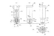
図1に示すように、切断装置1は、筐体としての本体カバー2と、本体カバー2内に配設されたプラテン3と、カッタ4(図4(c)参照)を保持するカッタホルダ5と、カッタホルダ5を支持するキャリッジ22とを備えると共に、カッタ4と被切断物6とを相対的に移動させるための第1及び第2移動手段7,8を備えている。本体カバー2は横長な矩形箱状をなしており、前面部には、プラテン3上面部に被切断物6を保持した保持シート10をセットするための横長な開口部2aが形成されている。尚、以下の説明では、切断装置1に対しユーザが位置する側を前方とし、その反対側を後方とする。そして、前後方向をY方向とし、Y方向と直交する左右方向をX方向とする。
<First Embodiment>
Hereinafter, a first embodiment of the present invention will be described with reference to FIGS.
As shown in FIG. 1, the cutting device 1 includes a main body cover 2 as a housing, a platen 3 disposed in the main body cover 2, and a cutter holder 5 that holds a cutter 4 (see FIG. 4C). And a carriage 22 for supporting the cutter holder 5 and first and second moving means 7 and 8 for relatively moving the cutter 4 and the workpiece 6. The body cover 2 has a horizontally long rectangular box shape, and a horizontally long opening 2 a for setting a holding sheet 10 holding the workpiece 6 on the upper surface of the platen 3 is formed on the front surface. In the following description, the side on which the user is located with respect to the cutting device 1 is the front, and the opposite side is the rear. The front-rear direction is the Y direction, and the left-right direction orthogonal to the Y direction is the X direction.

本体カバー2の右側には、ユーザに対して必要なメッセージ等の表示を行う表示手段としての液晶ディスプレイ(LCD)9aが設けられると共に、ユーザが各種の指示や選択、入力の操作を行うための複数の操作スイッチ9b(図9参照)が設けられている。
前記プラテン3は、前後一対の板材3a,3bからなり、上面部が水平面たるXY平面をなすように構成されている。プラテン3には、被切断物6を保持する保持シート10が載置されるようにセットされ、被切断物6の切断の際、保持シート10をプラテン3で受ける。詳しくは後述するが、保持シート10の上面には、左右両方の縁部10a,10bを除いた部分に粘着剤が塗布された粘着層10v(図5参照)が形成されており、粘着層10vに被切断物6が貼り付けられて保持される。
On the right side of the main body cover 2, a liquid crystal display (LCD) 9a is provided as display means for displaying necessary messages and the like for the user, and for the user to perform various instructions, selections, and input operations. A plurality of operation switches 9b (see FIG. 9) are provided.
The platen 3 includes a pair of front and rear plate members 3a and 3b, and is configured such that the upper surface portion forms an XY plane that is a horizontal plane. The platen 3 is set so that a holding sheet 10 that holds the workpiece 6 is placed thereon. When the workpiece 6 is cut, the holding sheet 10 is received by the platen 3. As will be described in detail later, an adhesive layer 10v (see FIG. 5) in which an adhesive is applied to the upper surface of the holding sheet 10 except for both the left and right edges 10a and 10b is formed. The object 6 to be cut is pasted and held.

前記第1移動手段7は、プラテン3の上面側で保持シート10をY方向(第1方向)へ移動させるものである。即ち、切断装置1における左右の側壁部11a,11bには、プラテン3の板材3a,3bの間に位置させて、駆動ローラ12とピンチローラ13が設けられている。駆動ローラ12とピンチローラ13は、X方向に延びて、側壁部11a,11bに対して回動可能に支持されている。また、駆動ローラ12とピンチローラ13は、前記XY平面に対して平行で、且つ上下方向に並ぶように配置されている。下側が駆動ローラ12で、上側がピンチローラ13である。図2に示すように、右側壁部11bには、駆動ローラ12右端部の後側に位置させて、クランク状の第1取付フレーム14が設けられている。第1取付フレーム14の内側には、Y軸モータ15が固定されている。   The first moving means 7 moves the holding sheet 10 in the Y direction (first direction) on the upper surface side of the platen 3. That is, the left and right side wall portions 11 a and 11 b in the cutting device 1 are provided with the driving roller 12 and the pinch roller 13 so as to be positioned between the plate members 3 a and 3 b of the platen 3. The drive roller 12 and the pinch roller 13 extend in the X direction and are supported so as to be rotatable with respect to the side wall portions 11a and 11b. The driving roller 12 and the pinch roller 13 are arranged so as to be parallel to the XY plane and aligned in the vertical direction. The lower side is a driving roller 12 and the upper side is a pinch roller 13. As shown in FIG. 2, a crank-shaped first mounting frame 14 is provided on the right side wall portion 11 b so as to be located on the rear side of the right end portion of the drive roller 12. A Y-axis motor 15 is fixed inside the first mounting frame 14.

Y軸モータ15は例えばステッピングモータからなり、回転軸15aは第1取付フレーム14を貫通しており、先端部に駆動ギヤ16aが固定されている。駆動ローラ12の右端部には、駆動ギヤ16aと噛合する従動ギヤ16bが固定されており、駆動ギヤ16aと従動ギヤ16bにより第1減速ギヤ機構16が構成される。詳しい図示は省略するが、左右の側壁部11a,11bには、ピンチローラ13の両端部を覆うバネ掛部材17a,17bが夫々設けられている。バネ掛部材17a,17bと、側壁部11a,11bの外面に突設されたバネ取付部18a(図1に左側の取付部18aのみ図示)との間には、引張コイルバネ19a,19bが掛け渡されるように設けられている。それゆえ、ピンチローラ13は、引張コイルバネ19a,19bにより、常時下方へ付勢されている。ピンチローラ13には、側壁部11a,11b寄りの部位に、左右一対の押圧部13a,13bが設けられている。押圧部13a,13bは、ピンチローラ13の他の部分よりも外径が少し大きく形成されており、保持シート10の左右両方の縁部10a,10bに接触して押圧する。また、ピンチローラ13における押圧部13a,13b間では、カッタホルダ5を支持するキャリッジ20がピンチローラ13上を摺動する。   The Y-axis motor 15 is composed of, for example, a stepping motor, the rotation shaft 15a passes through the first mounting frame 14, and the drive gear 16a is fixed to the tip portion. A driven gear 16b that meshes with the drive gear 16a is fixed to the right end portion of the drive roller 12, and the drive gear 16a and the driven gear 16b constitute the first reduction gear mechanism 16. Although detailed illustration is omitted, spring hook members 17a and 17b that cover both ends of the pinch roller 13 are provided on the left and right side wall portions 11a and 11b, respectively. The tension coil springs 19a and 19b are spanned between the spring hook members 17a and 17b and a spring mounting portion 18a (only the left mounting portion 18a is shown in FIG. 1) protruding from the outer surfaces of the side wall portions 11a and 11b. Is provided. Therefore, the pinch roller 13 is always urged downward by the tension coil springs 19a and 19b. The pinch roller 13 is provided with a pair of left and right pressing portions 13a and 13b at portions near the side wall portions 11a and 11b. The pressing portions 13 a and 13 b are formed to have a slightly larger outer diameter than the other portions of the pinch roller 13, and press against the left and right edge portions 10 a and 10 b of the holding sheet 10. Further, the carriage 20 that supports the cutter holder 5 slides on the pinch roller 13 between the pressing portions 13 a and 13 b of the pinch roller 13.

以上のように、保持シート10は、駆動ローラ12とピンチローラ13により上下方向から押圧挟持される。そして、Y軸モータ15を正転駆動、或は逆転駆動させると、その回転運動が第1減速ギヤ機構16を介して駆動ローラ12に伝わることで、保持シート10を被切断物6と共に後方或いは前方へ移動させる。これら駆動ローラ12、ピンチローラ13、Y軸モータ15、第1減速ギヤ機構16、引張コイルバネ19a,19b等は、第1移動手段7を構成する。   As described above, the holding sheet 10 is pressed and clamped from above and below by the drive roller 12 and the pinch roller 13. Then, when the Y-axis motor 15 is driven to rotate forward or reversely, the rotational motion is transmitted to the drive roller 12 via the first reduction gear mechanism 16 so that the holding sheet 10 is moved rearward or together with the workpiece 6 or Move forward. The driving roller 12, the pinch roller 13, the Y-axis motor 15, the first reduction gear mechanism 16, the tension coil springs 19a and 19b, and the like constitute the first moving means 7.

前記第2移動手段8は、キャリッジ20をカッタホルダ5ごとX方向(第2方向)へ移動させるものである。詳細には、図1、図2に示すように、左右の側壁部11a,11b間には、上端部に位置させて、左右方向に延びるガイド軸21が設けられている。ガイド軸21は、駆動ローラ12及びピンチローラ13と平行に配置されている。ガイド軸21は、キャリッジ20上部(後述の挿通孔部22)を貫通しており、キャリッジ20を左右方向へ摺動可能にガイドする。   The second moving means 8 moves the carriage 20 together with the cutter holder 5 in the X direction (second direction). Specifically, as shown in FIGS. 1 and 2, a guide shaft 21 extending in the left-right direction is provided between the left and right side wall portions 11a, 11b so as to be positioned at the upper end portion. The guide shaft 21 is disposed in parallel with the drive roller 12 and the pinch roller 13. The guide shaft 21 passes through the upper portion of the carriage 20 (an insertion hole portion 22 described later), and guides the carriage 20 to be slidable in the left-right direction.

図1、図2に示すように、切断装置1の後部には、左側壁部11aにL字状の第2取付フレーム24が設けられている。第2取付フレーム24には、X軸モータ26及び第2減速ギヤ機構27が配設されている。X軸モータ26は、例えばステッピングモータからなり、第2取付フレーム24の下面部に固定されている。図1に示すように、X軸モータ26の回転軸26aは第2取付フレーム24を貫通しており、先端部に駆動ギヤ27aが固定されている。駆動ギヤ27aの前方には、従動ギヤ27bが配置される。従動ギヤ27bは、第2取付フレーム24に回転可能に支持されており、駆動ギヤ27aと噛合する。駆動ギヤ27aと従動ギヤ27bにより、第2減速ギヤ機構27が構成される。従動ギヤ27bの上面にはプーリ28が設けられており、従動ギヤ27bとプーリ28は一体的に回転する。一方、図2において右側の第1取付フレーム14上面にはプーリ29が回転自在に取付けられている。これらプーリ28とプーリ29との間には、キャリッジ20の後端部(後述の取付部30(図4(b)参照))に連結された無端状のタイミングベルト31が掛装されている。   As shown in FIGS. 1 and 2, an L-shaped second mounting frame 24 is provided on the left side wall portion 11 a at the rear portion of the cutting device 1. An X-axis motor 26 and a second reduction gear mechanism 27 are disposed on the second mounting frame 24. The X-axis motor 26 is composed of a stepping motor, for example, and is fixed to the lower surface portion of the second mounting frame 24. As shown in FIG. 1, the rotation shaft 26a of the X-axis motor 26 passes through the second mounting frame 24, and a drive gear 27a is fixed to the tip. A driven gear 27b is disposed in front of the drive gear 27a. The driven gear 27b is rotatably supported by the second mounting frame 24 and meshes with the drive gear 27a. The drive gear 27a and the driven gear 27b constitute a second reduction gear mechanism 27. A pulley 28 is provided on the upper surface of the driven gear 27b, and the driven gear 27b and the pulley 28 rotate integrally. On the other hand, a pulley 29 is rotatably mounted on the upper surface of the first mounting frame 14 on the right side in FIG. Between the pulley 28 and the pulley 29, an endless timing belt 31 connected to a rear end portion of the carriage 20 (a mounting portion 30 described later (see FIG. 4B)) is hung.

ここで、X軸モータ26を正転駆動、或は逆転駆動させると、その回転運動が第2減速ギヤ機構27及びプーリ28を介してタイミングベルト31に伝わることで、キャリッジ20をカッタホルダ5ごと左方或いは右方へ移動させる。こうして、キャリッジ20とカッタホルダ5は、被切断物6の移動方向であるY方向と直交するX方向に移動する。上記のガイド軸21、X軸モータ26、第2減速ギヤ機構27、プーリ28,29、タイミングベルト31、キャリッジ20等は、第2移動手段8を構成する。   Here, when the X-axis motor 26 is driven to rotate forward or reversely, the rotational motion is transmitted to the timing belt 31 via the second reduction gear mechanism 27 and the pulley 28, so that the carriage 20 is moved together with the cutter holder 5 to the left. Move to the right or to the right. Thus, the carriage 20 and the cutter holder 5 move in the X direction orthogonal to the Y direction, which is the moving direction of the workpiece 6. The guide shaft 21, the X-axis motor 26, the second reduction gear mechanism 27, the pulleys 28 and 29, the timing belt 31, the carriage 20, etc. constitute the second moving means 8.

前記カッタホルダ5は、キャリッジ20に対して前面側に配置され、Z方向たる上下方向(第3方向)への移動が可能に支持されている。図3(b)に示すように、キャリッジ20は、略矩形板状をなす前壁部20cと、前壁部20cの上端及び下端を後方へ折り返すように形成した上縁部20a及び下縁部20bとを一体に有する。キャリッジ20の上縁部20aには、ガイド軸21に挿通される左右一対の挿通孔部22,22が上方へ張出すように設けられている。キャリッジ20の下縁部20bには、下面側が開放された断面略U字状の被ガイド体23が一体に設けられている。被ガイド体23は、左右方向に延びており、ピンチローラ13に対し上側から左右方向へ摺動可能に係合する。また、キャリッジ20の前壁部20cの後面側には、前記タイミングベルト31に連結される取付部30(図4(b)にのみ図示)が後方へ突出するように設けられている。こうして、キャリッジ20は、挿通孔部22,22に挿通されるガイド軸21によって左右方向へ摺動可能に支持されると共に、被ガイド体23がピンチローラ13に摺動可能に係合することで、ガイド軸21の回りに回転しないように姿勢が保持される。   The cutter holder 5 is disposed on the front side with respect to the carriage 20 and is supported so as to be movable in the vertical direction (third direction) as the Z direction. As shown in FIG. 3B, the carriage 20 includes a front wall portion 20c having a substantially rectangular plate shape, and an upper edge portion 20a and a lower edge portion formed so that the upper end and the lower end of the front wall portion 20c are folded back. 20b integrally. A pair of left and right insertion holes 22, 22 inserted through the guide shaft 21 are provided on the upper edge portion 20 a of the carriage 20 so as to project upward. A guided body 23 having a substantially U-shaped cross section with an open lower surface is integrally provided on the lower edge portion 20 b of the carriage 20. The guided body 23 extends in the left-right direction, and engages with the pinch roller 13 so as to be slidable in the left-right direction from above. A mounting portion 30 (shown only in FIG. 4B) connected to the timing belt 31 is provided on the rear surface side of the front wall portion 20c of the carriage 20 so as to protrude rearward. Thus, the carriage 20 is slidably supported in the left-right direction by the guide shaft 21 inserted through the insertion holes 22 and 22, and the guided body 23 is slidably engaged with the pinch roller 13. The posture is held so as not to rotate around the guide shaft 21.

図3(b)に示すように、キャリッジ20の前壁部20cには、第1係合部32a及び第2係合部32bが上下方向に延設されている。第1係合部32aは、前壁部20cから前方に突出し平面視にてL字状をなす一方、第2係合部32bはスリット状をなしている。これら第1係合部32a及び第2係合部32bは、後述するカッタホルダ5の第1被係合部33a及び第2被係合部33b(図4(b)参照)と係合した状態で、カッタホルダ5を上下方向へ移動可能に支持する。
図3(a)、図4(b)等に示すように、キャリッジ20における前壁部20cの左部に、クランク状の第3取付フレーム35が設けられている。第3取付フレーム35には、Z軸モータ34及び第3減速ギヤ機構36が配設されている。Z軸モータ34は、例えばステッピングモータからなり、第3取付フレーム35における前側の取付片35aの前面部に固定されている。図4(b)に示すように、Z軸モータ34の回転軸34aは取付片35aを貫通しており、先端部に駆動ギヤ34bが固定されている。一方、第3取付フレーム35における後側の取付片35bには、ギヤ軸37が前方へ突出するように設けられている。ギヤ軸37には、駆動ギヤ34bと噛合する中間ギヤ38と、当該中間ギヤ38と一体的に形成された小径のピニオン39とが回転可能に装着され、ギヤ軸37前端部に係止された止め輪40により抜け止めされている。これら駆動ギヤ34b、中間ギヤ38、及びピニオン39により第3減速ギヤ機構36が構成されている。
As shown in FIG. 3B, a first engagement portion 32 a and a second engagement portion 32 b are extended in the vertical direction on the front wall portion 20 c of the carriage 20. The first engaging portion 32a protrudes forward from the front wall portion 20c and has an L shape in plan view, while the second engaging portion 32b has a slit shape. The first engaging portion 32a and the second engaging portion 32b are engaged with a first engaged portion 33a and a second engaged portion 33b (see FIG. 4B) of the cutter holder 5, which will be described later. The cutter holder 5 is supported so as to be movable in the vertical direction.
As shown in FIG. 3A, FIG. 4B, and the like, a crank-shaped third attachment frame 35 is provided on the left portion of the front wall portion 20c of the carriage 20. The third mounting frame 35 is provided with a Z-axis motor 34 and a third reduction gear mechanism 36. The Z-axis motor 34 is composed of, for example, a stepping motor, and is fixed to the front surface portion of the front mounting piece 35 a in the third mounting frame 35. As shown in FIG. 4B, the rotating shaft 34a of the Z-axis motor 34 passes through the mounting piece 35a, and the drive gear 34b is fixed to the tip. On the other hand, a gear shaft 37 is provided on the rear mounting piece 35b of the third mounting frame 35 so as to protrude forward. An intermediate gear 38 that meshes with the drive gear 34 b and a small-diameter pinion 39 that is integrally formed with the intermediate gear 38 are rotatably mounted on the gear shaft 37 and locked to the front end portion of the gear shaft 37. The retaining ring 40 prevents it from coming off. The drive gear 34b, the intermediate gear 38, and the pinion 39 constitute a third reduction gear mechanism 36.

図3(a)、図4(a)〜(c)に示すように、カッタホルダ5のホルダ本体43は、上下方向に延びる左半部の軸収容部44と右半部の段落ちした筒状部45とを一体に有している。図4(b)に示すように、軸収容部44の後壁側には第1被係合部33aが設けられ、筒状部45の後壁側には第2被係合部33bが設けられている。第1被係合部33aはキャリッジ20の第1係合部32aと係合し、第2被係合突部33bはキャリッジ20の第2係合部32bと夫々係合可能なように形成されている。ホルダ本体43は、キャリッジ20に対して、第1被係合部33aを第1係合部32aに、第2被係合部33bを第2係合部32bに夫々係合させながら、上方から下方に向かって差し込むようにして組み付けられる。これにより、ホルダ本体43は、キャリッジ20に対して上下方向への移動が可能に支持される。   As shown in FIGS. 3A and 4A to 4C, the holder body 43 of the cutter holder 5 has a left half shaft housing portion 44 extending vertically and a right half stepped cylindrical shape. It has the part 45 integrally. As shown in FIG. 4B, a first engaged portion 33a is provided on the rear wall side of the shaft accommodating portion 44, and a second engaged portion 33b is provided on the rear wall side of the tubular portion 45. It has been. The first engaged portion 33a is engaged with the first engaging portion 32a of the carriage 20, and the second engaged protrusion 33b is formed so as to be engageable with the second engaging portion 32b of the carriage 20. ing. The holder body 43 is engaged with the carriage 20 from above while engaging the first engaged portion 33a with the first engaging portion 32a and the second engaged portion 33b with the second engaging portion 32b. It is assembled by inserting it downward. Thus, the holder main body 43 is supported so as to be movable in the vertical direction with respect to the carriage 20.

図4(c)に示すように、ホルダ本体43の軸収容部44には、その底壁部44aと棚部44bとを上下に貫通する取付軸48が設けられている。取付軸48は、軸収容部44の底壁部44aと棚部44bを上下両側から挟むように配置された一対の止め輪49により、ホルダ本体43に対して固定されている。取付軸48の左方には、ラック形成部材41のラック41aが第3減速ギヤ機構36のピニオン39と噛合するように配置されている。ラック形成部材41は、取付軸48に沿って上下方向に延びるラック41aと、その上端部及び中間部から夫々右側に延出する一対の取付片41b,41cとを一体に有している。ラック形成部材41は、中間部の取付片41cを棚部44bの下側に位置させた状態で、両取付片41b,41cを貫通する取付軸48に対して、軸方向への移動が可能に取付けられている。また、取付軸48には、ラック形成部材41の取付片41cと軸収容部44の底壁部44aとの間に、圧縮コイルバネ50が外装されている。   As shown in FIG. 4C, the shaft accommodating portion 44 of the holder main body 43 is provided with an attachment shaft 48 that vertically penetrates the bottom wall portion 44a and the shelf portion 44b. The attachment shaft 48 is fixed to the holder main body 43 by a pair of retaining rings 49 arranged so as to sandwich the bottom wall portion 44a and the shelf portion 44b of the shaft accommodating portion 44 from both upper and lower sides. On the left side of the mounting shaft 48, the rack 41 a of the rack forming member 41 is disposed so as to mesh with the pinion 39 of the third reduction gear mechanism 36. The rack forming member 41 integrally includes a rack 41a extending in the vertical direction along the mounting shaft 48 and a pair of mounting pieces 41b and 41c extending rightward from the upper end portion and the intermediate portion thereof. The rack forming member 41 can move in the axial direction with respect to the mounting shaft 48 penetrating both the mounting pieces 41b and 41c with the intermediate mounting piece 41c positioned below the shelf 44b. Installed. A compression coil spring 50 is externally mounted on the mounting shaft 48 between the mounting piece 41 c of the rack forming member 41 and the bottom wall portion 44 a of the shaft housing portion 44.

ラック形成部材41のラック41aは、第3減速ギヤ機構36のピニオン39と噛合する。従って、Z軸モータ34を正転駆動、或は逆転駆動させると、その駆動力が駆動ギヤ34b、中間ギヤ38、及びピニオン39を介してラック形成部材41に伝わることにより、ホルダ本体43を上方或いは下方へ昇降させる。これによって、ホルダ本体43(カッタホルダ5)は、カッタ4の刃先4bが被切断物6を貫通する下降位置(図5、図8参照)と、刃先4bが被切断物6から所定距離、離間する上昇位置(図4、図6参照)との間で移動する。カッタホルダ5の下降位置では、圧縮コイルバネ50がラック形成部材41の取付片41cで下方へ圧縮された状態となる。このため、圧縮コイルバネ50の付勢力(弾性力)により所定のカッタ圧(カッタ4が被切断物6を押圧する力)が得られる一方、当該付勢力に抗してカッタホルダ5(カッタ4)の上方への移動を許容する。上記した第3減速ギヤ機構36、Z軸モータ34、ラック形成部材41等は、カッタホルダ5を上下方向へ移動させる第3移動手段42を構成する。   The rack 41 a of the rack forming member 41 meshes with the pinion 39 of the third reduction gear mechanism 36. Therefore, when the Z-axis motor 34 is driven to rotate forward or reversely, the driving force is transmitted to the rack forming member 41 via the drive gear 34b, the intermediate gear 38, and the pinion 39, so that the holder body 43 is moved upward. Alternatively, it is moved up and down. As a result, the holder body 43 (the cutter holder 5) is separated from the workpiece 6 by a predetermined distance from the lowered position (see FIGS. 5 and 8) where the blade edge 4b of the cutter 4 penetrates the workpiece 6 and the cutting edge 6b. It moves between the raised positions (see FIGS. 4 and 6). At the lowered position of the cutter holder 5, the compression coil spring 50 is compressed downward by the mounting piece 41 c of the rack forming member 41. For this reason, a predetermined cutter pressure (force by which the cutter 4 presses the workpiece 6) is obtained by the urging force (elastic force) of the compression coil spring 50, while the cutter holder 5 (cutter 4) resists the urging force. Allow upward movement. The above-described third reduction gear mechanism 36, Z-axis motor 34, rack forming member 41, and the like constitute third moving means 42 that moves the cutter holder 5 in the vertical direction.

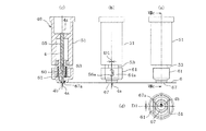
こうして、カッタホルダ5は、第1移動手段7、第2移動手段8、及び第3移動手段42により、被切断物6に対して相対的に移動させる切断手段として構成されている。カッタホルダ5は、前記ホルダ本体43の筒状部45に、カッタ4をZ軸の回りに回動可能に支持する支持装置46を備えると共に、被切断物6を押圧するための押圧装置47を備える。これら支持装置46、カッタ4及び押圧装置47の構成について、図6(a)〜(e)に示す正面図、左側面図、縦断左側面図、底面図及び横断底面図も参照しながら詳述する。
図4(c)、図6(a)〜(e)に示すように、支持装置46は、ホルダ本体43の筒状部45の内部に配置される略筒状の支持ベース部材51を備える。支持ベース部材51の上端部には、筒状部45の上端で支持されるフランジ部51aが径方向外側へ張出すように形成されている。支持ベース部材51は、筒状部45の上方から収容された状態で、筒状部45のやや上寄りの部位を径方向に貫通するネジ52により、ホルダ本体43に固定されている。図6(c)に示すように、支持ベース部材51の内部には、下端部に軸受部材54が固定されると共に、上寄りの位置に、カッタ4のカッタ軸55外周面と摺接する軸受部51bが一体形成されている。これら軸受部材54及び軸受部51bは、カッタ4をその中心軸線4zの回りに回動可能に支持するための軸受手段として構成される。
Thus, the cutter holder 5 is configured as a cutting unit that moves relative to the workpiece 6 by the first moving unit 7, the second moving unit 8, and the third moving unit 42. The cutter holder 5 includes a support device 46 that supports the cutter 4 so as to be rotatable about the Z axis, and a pressing device 47 that presses the workpiece 6 in the cylindrical portion 45 of the holder main body 43. . The configurations of the support device 46, the cutter 4 and the pressing device 47 will be described in detail with reference to the front view, the left side view, the longitudinal left side view, the bottom view, and the transverse bottom view shown in FIGS. To do.
As shown in FIG. 4C and FIGS. 6A to 6E, the support device 46 includes a substantially cylindrical support base member 51 disposed inside the cylindrical portion 45 of the holder main body 43. At the upper end portion of the support base member 51, a flange portion 51a supported by the upper end of the tubular portion 45 is formed so as to project outward in the radial direction. The support base member 51 is fixed to the holder main body 43 by a screw 52 that penetrates a portion slightly above the cylindrical portion 45 in the radial direction while being accommodated from above the cylindrical portion 45. As shown in FIG. 6C, a bearing member 54 is fixed to the lower end portion of the support base member 51, and the bearing portion is in sliding contact with the outer peripheral surface of the cutter shaft 55 of the cutter 4 at an upper position. 51b is integrally formed. The bearing member 54 and the bearing portion 51b are configured as bearing means for supporting the cutter 4 so as to be rotatable around its central axis 4z.

前記カッタ4は、基部としての丸棒状をなすカッタ軸55と、先端部(下端部)の刃先4bとを一体に形成してなる。カッタ軸55の下部側には、後述する嵌合支持部材53に嵌合される嵌合突部55aが径方向外側へ突出するように設けられている。カッタ4の刃先4bは、図5に示すように被切断物6に対して傾斜しており、最下端の切先4aがカッタ軸55の中心軸線4zから距離dだけ偏心した位置に形成されている。尚、本実施形態の「刃先」とは、被切断物6を切断するカッタ4の先端部分を称するものであり、切先4aを包含する。   The cutter 4 is formed by integrally forming a cutter shaft 55 having a round bar shape as a base portion and a cutting edge 4b at a distal end portion (lower end portion). On the lower side of the cutter shaft 55, a fitting protrusion 55a fitted to a fitting support member 53 described later is provided so as to protrude radially outward. The cutting edge 4b of the cutter 4 is inclined with respect to the workpiece 6 as shown in FIG. 5, and the lowermost cutting edge 4a is formed at a position eccentric from the central axis 4z of the cutter shaft 55 by a distance d. Yes. The “blade edge” in the present embodiment refers to the tip portion of the cutter 4 that cuts the workpiece 6 and includes the cutting edge 4a.

ここで、図6(e)は、図6(b)のVIe−VIe線に沿う断面、つまりカッタ4が延びるZ方向に対する垂直な断面を示している。同図に示すように、カッタ4の下端部における刃先4b側の断面は、略三角形状をなす。また、カッタ4の刃先4bが貫通する貫通孔67a(図6(d))は、当該断面と略相似形の略三角形状をなしており、刃先4bの先端に向かって徐々に小さくなる先細状に形成されている。カッタ4は、カッタホルダ5が下降位置へ移動された時に、図5に示すように刃先4bが保持シート10上の被切断物6を貫通し、且つプラテン3の板材3b上面に到達しない高さに設定してある。   Here, FIG. 6E shows a cross section taken along line VIe-VIe in FIG. 6B, that is, a cross section perpendicular to the Z direction in which the cutter 4 extends. As shown in the figure, the cross section on the blade edge 4b side at the lower end of the cutter 4 has a substantially triangular shape. Further, the through hole 67a (FIG. 6D) through which the blade edge 4b of the cutter 4 penetrates has a substantially triangular shape that is substantially similar to the cross section, and is gradually tapered toward the tip of the blade edge 4b. Is formed. When the cutter holder 5 is moved to the lowered position, the cutter 4 has a height at which the cutting edge 4b penetrates the workpiece 6 on the holding sheet 10 and does not reach the upper surface of the plate 3b of the platen 3 as shown in FIG. It is set.

図6(a)(b)(e)に示すように、前記嵌合支持部材53は、支持ベース部材51に比し径小な寸法に設定されると共に、外周部に一対の平坦部56,57が形成されおり、軸方向から見て小判形をなす。各平坦部56,57は、中心軸線4zの方向に延びており、中心軸線4zに対して対称な位置に小突起56a,57aが形成されている。図6(c)に示すように、嵌合支持部材53の内部には、カッタ軸55が圧入される挿通孔58が軸方向に延びるように設けられている。嵌合支持部材53の下端部には、挿通孔58を径方向外側に窪ませた嵌合凹部58aが形成されている。嵌合凹部58aはカッタ軸55の嵌合突部55aと嵌合する。カッタ軸55は、嵌合支持部材53の挿通孔58に対して、嵌合突部55aと嵌合凹部58aが嵌合する位置まで圧入されて、嵌合支持部材53に組み付けられる。このとき、嵌合支持部材53の平坦部56,57が、刃先4bの向きと平行となるように組み付けられる。このように、カッタ4は、嵌合支持部材53に固定される。   As shown in FIGS. 6A, 6B, and 6E, the fitting support member 53 is set to have a smaller diameter than the support base member 51, and a pair of flat portions 56, 57 is formed and has an oval shape when viewed from the axial direction. The flat portions 56 and 57 extend in the direction of the central axis 4z, and small protrusions 56a and 57a are formed at positions symmetrical to the central axis 4z. As shown in FIG. 6C, an insertion hole 58 into which the cutter shaft 55 is press-fitted is provided in the fitting support member 53 so as to extend in the axial direction. A fitting recess 58a is formed at the lower end of the fitting support member 53. The fitting recess 58a is formed by recessing the insertion hole 58 radially outward. The fitting recess 58 a is fitted with the fitting protrusion 55 a of the cutter shaft 55. The cutter shaft 55 is press-fitted into the insertion hole 58 of the fitting support member 53 to a position where the fitting projection 55 a and the fitting recess 58 a are fitted, and is assembled to the fitting support member 53. At this time, the flat portions 56 and 57 of the fitting support member 53 are assembled so as to be parallel to the direction of the blade edge 4b. In this way, the cutter 4 is fixed to the fitting support member 53.

嵌合支持部材53の上端部には、段落ち状の被支持部59が形成されている。カッタ4は嵌合支持部材53に一体に組み付けられた状態で、嵌合支持部材53の被支持部59が、支持ベース部材51内に軸受部材54を介して回動可能に嵌挿される。嵌合支持部材53における挿通孔58の外周側には、挿通孔58と同心状のバネ収容溝53aが設けられている。バネ収容溝53aは、嵌合支持部材53の下面側から上方へ延びるように形成されており、後述する圧縮コイルバネ60の上半部が収容される。上記した支持ベース部材51、軸受部材54及び嵌合支持部材53は、カッタ4を中心軸線4zの回りに回動可能に支持する支持手段として支持装置46を構成する。   A stepped supported portion 59 is formed at the upper end portion of the fitting support member 53. In a state where the cutter 4 is integrally assembled with the fitting support member 53, the supported portion 59 of the fitting support member 53 is rotatably inserted into the support base member 51 via the bearing member 54. A spring accommodating groove 53 a concentric with the insertion hole 58 is provided on the outer peripheral side of the insertion hole 58 in the fitting support member 53. The spring accommodating groove 53a is formed to extend upward from the lower surface side of the fitting support member 53, and accommodates an upper half portion of a compression coil spring 60 described later. The support base member 51, the bearing member 54, and the fitting support member 53 described above constitute a support device 46 as support means for supporting the cutter 4 so as to be rotatable about the central axis 4z.

前記押圧装置47は、被切断物6を押える押え部材61と、押え部材61を被切断物6側へ弾性付勢する圧縮コイルバネ60を備えた押え手段である。押え部材61は樹脂材料からなり、嵌合支持部材53の下部を収容する容器状に形成されている。押え部材61の外周部は、嵌合支持部材53の外周より径大な一対の曲面壁62,63と、それら曲面壁62,63の両側縁に連なる一対の平坦壁64,65とからなり、軸方向から見て小判形をなす(図6(d)(e)参照)。曲面壁62,63の内面と、嵌合支持部材53の外周面との間には所定の空間(隙間)がある。一方、平坦壁64,65の内面は、嵌合支持部材53の平坦部56,57と摺接する。平坦壁64,65には、嵌合支持部材53の小突起56a,57aを覗かせる一対の窓部64a,65aが相互に対向するように形成されている。図6(b)(e)に示すように、窓部64a,65aは、略矩形状をなす孔部である。   The pressing device 47 is a pressing means including a pressing member 61 that presses the workpiece 6 and a compression coil spring 60 that elastically biases the pressing member 61 toward the workpiece 6. The pressing member 61 is made of a resin material and is formed in a container shape that houses the lower portion of the fitting support member 53. The outer peripheral portion of the pressing member 61 includes a pair of curved walls 62 and 63 having a diameter larger than that of the outer periphery of the fitting support member 53, and a pair of flat walls 64 and 65 connected to both side edges of the curved walls 62 and 63. An oval shape is seen from the axial direction (see FIGS. 6D and 6E). There is a predetermined space (gap) between the inner surfaces of the curved walls 62 and 63 and the outer peripheral surface of the fitting support member 53. On the other hand, the inner surfaces of the flat walls 64 and 65 are in sliding contact with the flat portions 56 and 57 of the fitting support member 53. On the flat walls 64 and 65, a pair of window portions 64a and 65a through which the small protrusions 56a and 57a of the fitting support member 53 can be seen are formed so as to face each other. As shown in FIGS. 6B and 6E, the window portions 64a and 65a are hole portions having a substantially rectangular shape.

押え部材61の底壁部66には、下方に突出させた接触部67が設けられている。接触部67の下端面は、円形をなす水平な平坦面であり、被切断物6に対して面接触する。接触部67の下側稜線は、曲面(R面取)に形成されている。接触部67には、カッタ4が延びる上下方向に貫通する貫通孔67aが形成されている。貫通孔67aは、図6(d)に示すように略三角形状に形成されており、前述したカッタ4の刃先4b側の断面と略相似形をなす。貫通孔67aの延びる方向(図6(d)における紙面上下方向)は、平坦壁64,65と平行である。この場合、貫通孔67aは、カッタ4の刃先4bに対して僅かの隙間を有して係合するよう、刃先4b側の断面よりも僅かに大きな寸法に設定されている。詳しい説明は後述するが、切断時には、図5に示す貫通孔67aの壁面とカッタ4との間に、同図に矢印で示すカッタ4の相対移動の方向とは反対側に、符号G1で示す隙間ができる。また、図6(c)(d)に示すように、貫通孔67aは、接触部67において中心軸線4zに対し切先4a寄りに偏心した位置に形成されている。こうして、押え部材61は、貫通孔67aに切先4aがスムーズに挿通され、且つ貫通孔67a内でカッタ4の刃先4b側との係合が可能に構成されている。   The bottom wall portion 66 of the pressing member 61 is provided with a contact portion 67 that protrudes downward. The lower end surface of the contact portion 67 is a circular flat horizontal surface that makes surface contact with the workpiece 6. The lower ridge line of the contact portion 67 is formed as a curved surface (R chamfer). The contact portion 67 is formed with a through hole 67a penetrating in the vertical direction in which the cutter 4 extends. The through hole 67a is formed in a substantially triangular shape as shown in FIG. 6 (d), and is substantially similar to the cross section of the cutter 4 on the blade edge 4b side. The direction in which the through hole 67a extends (the vertical direction in FIG. 6D) is parallel to the flat walls 64 and 65. In this case, the through hole 67a is set to have a slightly larger dimension than the cross section on the blade edge 4b side so as to be engaged with the blade edge 4b of the cutter 4 with a slight gap. Although detailed description will be given later, at the time of cutting, it is indicated by reference numeral G1 between the wall surface of the through-hole 67a shown in FIG. There is a gap. Further, as shown in FIGS. 6C and 6D, the through hole 67a is formed in the contact portion 67 at a position eccentric to the cutting edge 4a with respect to the central axis 4z. Thus, the pressing member 61 is configured such that the cutting edge 4a is smoothly inserted into the through hole 67a and can be engaged with the cutting edge 4b of the cutter 4 in the through hole 67a.

前記圧縮コイルバネ60は、押え部材61を被切断物6側へ付勢する付勢部材である。圧縮コイルバネ60は、押え部材61の底壁部66と嵌合支持部材53のバネ収容溝53aとの間に配置され、押え部材61と共に嵌合支持部材53に対して下側から組み付けられる。この組み付けでは、嵌合支持部材53に嵌合されたカッタ4の刃先4bの向きに、押え部材61の貫通孔67aの向き(略三角形状である孔の向き)を合わせ、押え部材61の平坦壁64,65内面を、嵌合支持部材53の平坦部56,57に沿わせて装着する。この装着の際、押え部材61を、圧縮コイルバネ60の圧縮方向の弾性力に抗しながら上方に押し込むと、平坦壁64,65の上端が小突起56a,57aを乗り越えるように外側へ弾性変形しながら嵌り込む。そして、押え部材61の窓部64a,65aが小突起56a,57aに到達すると、外側に撓んでいた平坦壁64,65の上端が元に戻り、窓部64a,65aと小突起56a,57aが係合可能な状態となり、組み付けが完了する。   The compression coil spring 60 is a biasing member that biases the pressing member 61 toward the workpiece 6 side. The compression coil spring 60 is disposed between the bottom wall portion 66 of the pressing member 61 and the spring accommodating groove 53 a of the fitting support member 53, and is assembled to the fitting support member 53 together with the pressing member 61 from below. In this assembly, the orientation of the through hole 67a of the presser member 61 (the direction of the hole having a substantially triangular shape) is aligned with the direction of the cutting edge 4b of the cutter 4 fitted to the fitting support member 53, and the presser member 61 is flat. The inner surfaces of the walls 64 and 65 are mounted along the flat portions 56 and 57 of the fitting support member 53. At the time of mounting, when the pressing member 61 is pushed upward while resisting the elastic force of the compression coil spring 60 in the compression direction, the upper ends of the flat walls 64 and 65 are elastically deformed outward so as to get over the small protrusions 56a and 57a. Fit while. When the window portions 64a and 65a of the holding member 61 reach the small projections 56a and 57a, the upper ends of the flat walls 64 and 65 bent outward are returned to the original, and the window portions 64a and 65a and the small projections 56a and 57a are restored. Engagement is possible and assembly is complete.

このように、押え部材61は、圧縮コイルバネ60を介して嵌合支持部材53に連結され、圧縮コイルバネ60により被切断物6側へ付勢される。また、押え部材61は、その平坦壁64,65が嵌合支持部材53の平坦部56,57に面接触するため、嵌合支持部材53及びカッタ4並びに圧縮コイルバネ60と一体的に回動する。こうして、押圧装置47は、カッタ4が中心軸線4zの回りに回動して刃先4bの向きが変更されることに伴い、押え部材61が刃先4bと連動して回動するように構成される。また、押え部材61の曲面壁62,63の内面と、嵌合支持部材53の外周曲面との間には所定の空間(隙間)があるので、押え部材61は、嵌合支持部材53に対して、前記空間(隙間)分だけ貫通孔67aの延びる方向に移動が可能である。換言すれば、押え部材61は、貫通孔67aがカッタ4の刃先4bに接触する方向に移動が可能である。   Thus, the pressing member 61 is connected to the fitting support member 53 via the compression coil spring 60 and is urged toward the workpiece 6 by the compression coil spring 60. Further, since the flat walls 64 and 65 are in surface contact with the flat portions 56 and 57 of the fitting support member 53, the pressing member 61 rotates integrally with the fitting support member 53, the cutter 4, and the compression coil spring 60. . Thus, the pressing device 47 is configured such that the pressing member 61 rotates in conjunction with the cutting edge 4b as the cutter 4 rotates about the central axis 4z and the orientation of the cutting edge 4b is changed. . Further, since there is a predetermined space (gap) between the inner surfaces of the curved walls 62 and 63 of the presser member 61 and the outer peripheral curved surface of the fitting support member 53, the presser member 61 is located with respect to the fitting support member 53. Thus, it is possible to move in the extending direction of the through hole 67a by the space (gap). In other words, the pressing member 61 can move in the direction in which the through hole 67 a contacts the blade edge 4 b of the cutter 4.

図6(b)に示すように、押え部材61は、カッタホルダ5の上昇位置において、窓部64a,65aの上縁で小突起56a,57aに係止されるため、圧縮コイルバネ60の付勢力が作用しても抜け落ちない。また、カッタホルダ5の上昇位置では、押え部材61内にカッタ4の刃先4bが収容され、刃先4bは露出しない。一方、カッタホルダ5の下降位置では、図8に示すように、圧縮コイルバネ60が更に圧縮され、その付勢力(弾性力)により押え部材61を下方に押圧する。このように、押え部材61が被切断物6を押圧する。   As shown in FIG. 6B, the pressing member 61 is locked to the small protrusions 56 a and 57 a at the upper edges of the window portions 64 a and 65 a at the raised position of the cutter holder 5, so that the urging force of the compression coil spring 60 is increased. Even if it acts, it will not fall out. Further, at the raised position of the cutter holder 5, the cutting edge 4b of the cutter 4 is accommodated in the pressing member 61, and the cutting edge 4b is not exposed. On the other hand, in the lowered position of the cutter holder 5, as shown in FIG. 8, the compression coil spring 60 is further compressed, and the pressing member 61 is pressed downward by its urging force (elastic force). Thus, the pressing member 61 presses the workpiece 6.

そして、押え部材61は、後述するフィード時、或は切断時に接触部67と被切断物6との間で摩擦力が生じることにより、カッタ4の刃先4bに接触する方向へ移動する。即ちフィード時には、押え部材61は、カッタ4の刃先4bと貫通孔67aとが隙間無く接触するようになる。   The pressing member 61 moves in a direction in which the pressing member 61 comes into contact with the blade edge 4b of the cutter 4 when a frictional force is generated between the contact portion 67 and the workpiece 6 during feeding or cutting described later. That is, at the time of feeding, the pressing member 61 comes into contact with the blade edge 4b of the cutter 4 and the through hole 67a without any gap.

図5に示すように、前記保持シート10は、被切断物6を保持するための粘着層10vを有する。被切断物6は、切断装置1にて切断する際、粘着層10vの粘着力と押圧装置47の押圧力とによって、保持シート10に対して移動不能に保持される。保持部材としての保持シート10は、例えば、樹脂材料からなり、平板矩形状(図1参照)に形成されている。粘着層10vは、保持シート10の上側の面つまりカッタ4との対向面に、粘着剤が塗布されることにより形成されている。粘着層10vは、例えば紙、布、樹脂フィルム等のシート状の被切断物6を剥離可能に保持する。粘着層10vの粘着力は、被切断物6を粘着層10vから剥がす際、当該被切断物6が破れることがなく且つ簡単に剥がせるよう比較的小さい値に設定されている。   As shown in FIG. 5, the holding sheet 10 has an adhesive layer 10 v for holding the workpiece 6. When the workpiece 6 is cut by the cutting device 1, the workpiece 6 is held immovably with respect to the holding sheet 10 by the adhesive force of the adhesive layer 10 v and the pressing force of the pressing device 47. The holding sheet 10 as a holding member is made of, for example, a resin material and is formed in a flat plate rectangular shape (see FIG. 1). The adhesive layer 10v is formed by applying an adhesive to the upper surface of the holding sheet 10, that is, the surface facing the cutter 4. The adhesive layer 10v holds, for example, a sheet-like workpiece 6 such as paper, cloth, or resin film in a peelable manner. The adhesive strength of the adhesive layer 10v is set to a relatively small value so that the workpiece 6 is not torn when the workpiece 6 is peeled from the adhesive layer 10v and can be easily peeled off.

次に、切断装置1の制御系の構成について図9のブロック図を参照しながら説明する。
切断装置1全体の制御を司る制御回路(制御手段)71は、コンピュータ(CPU)を主体に構成されており、ROM72、RAM73、外部メモリ74が接続されている。ROM72には、切断動作を制御するための切断制御プログラムや、各種制御用データ等が記憶されている。RAM73には、各種処理に必要なデータやプログラムが一時的に記憶される。外部メモリ74には、複数種類の切断データが記憶されている。前記切断データは、切断ラインLを構成するn個の線分L〜Lに夫々対応する線分データを含む。
Next, the configuration of the control system of the cutting apparatus 1 will be described with reference to the block diagram of FIG.
A control circuit (control means) 71 that controls the entire cutting apparatus 1 is mainly composed of a computer (CPU), and a ROM 72, a RAM 73, and an external memory 74 are connected thereto. The ROM 72 stores a cutting control program for controlling the cutting operation, various control data, and the like. The RAM 73 temporarily stores data and programs necessary for various processes. The external memory 74 stores a plurality of types of cutting data. The cut data includes line segment data corresponding to n line segments L 1 to L n constituting the cut line L, respectively.

例えば、図10に示すように、保持シート10に保持された紙等のシートである被切断物6に、「三角形」形状の模様を切断する場合、切断データは、当該切断ラインLを構成する3個の線分L〜Lからなる3個の線分データを有する。具体的には、線分L〜Lは、夫々対応する始点L1S〜L3S及び終点L1E〜L3Eを有する。また、線分L〜Lは連続的に連なり、閉じた1つの切断ラインLを構成することから、夫々の線分の始点は隣り合う線分の終点と一致し、夫々の線分の終点は隣り合う線分の始点と一致する。線分データは、対応する線分L〜Lの始点及び終点が夫々XY座標によって示される。 For example, as shown in FIG. 10, when a “triangular” pattern is cut on a workpiece 6 that is a sheet of paper or the like held on a holding sheet 10, the cutting data forms the cutting line L. Three line segment data composed of three line segments L 1 to L 3 are included. Specifically, the line segments L 1 to L 3 have corresponding start points L 1S to L 3S and end points L 1E to L 3E , respectively. Further, since the line segments L 1 to L 3 are continuously connected to form one closed cut line L, the start point of each line segment coincides with the end point of the adjacent line segment, and each line segment The end point coincides with the start point of the adjacent line segment. In the line segment data, the start point and the end point of the corresponding line segments L 1 to L 3 are indicated by XY coordinates, respectively.

制御回路71には、各種の操作スイッチ9bの操作信号が入力されると共に、液晶ディスプレイ9aの表示を制御する。このとき、ユーザは、液晶ディスプレイ9aの表示を見ながら、各種操作スイッチ9bを操作することによって、所望する形状の切断データを選択指定する。制御回路71には、切断装置1の開口部2aからセットされた保持シート10を検出するための検出センサ等、各種検出センサ75の検出信号が入力される。また、制御回路71には、Y軸モータ15、X軸モータ26、Z軸モータ34を夫々駆動する駆動回路76,77,78が接続されている。制御回路71は、切断制御プログラムの実行により前記切断データに基づいて、Y軸モータ15、X軸モータ26、Z軸モータ34等の各種アクチュエータを制御し、保持シート10上の被切断物6に対する切断動作を自動で実行させる。   The control circuit 71 receives operation signals from various operation switches 9b and controls display on the liquid crystal display 9a. At this time, the user selects and designates cutting data having a desired shape by operating various operation switches 9b while watching the display on the liquid crystal display 9a. Detection signals of various detection sensors 75 such as a detection sensor for detecting the holding sheet 10 set from the opening 2 a of the cutting device 1 are input to the control circuit 71. The control circuit 71 is connected to drive circuits 76, 77, 78 for driving the Y-axis motor 15, the X-axis motor 26, and the Z-axis motor 34, respectively. The control circuit 71 controls various actuators such as the Y-axis motor 15, the X-axis motor 26, and the Z-axis motor 34 based on the cutting data by executing the cutting control program, and controls the workpiece 6 on the holding sheet 10. The cutting operation is automatically executed.

上記構成の作用について説明する。尚、切断する形状は、前記の「三角形」を例とし、被切断物6としては一般的な紙を使用する。
切断装置1において被切断物6の切断開始前の状態では、カッタホルダ5が上昇位置に移動されている。この上昇位置では、図6(c)に示すように、カッタ4の刃先4bは、押え部材61に収容されており、露出しない。また、押え部材61は、図6(d)に示すように中心軸線4zの方向から見て、刃先4bの向きと貫通孔67aの向きが揃い、且つ、外周の曲面壁62,63が支持ベース部材51外周と揃うように中心位置で保持されている。一方、ユーザは、被切断物6を粘着層10vに貼り付けるようにして保持シート10に保持させる。そして、保持シート10を、切断装置1の開口部2aからセットする。そして、ユーザは、例えば外部メモリ74に記憶されている切断データの中から所望の切断データを選択すると、切断データが外部メモリ74から読み出されてRAM73のメモリに記憶される。そして、操作スイッチ9bが操作されると、制御回路71は、その操作信号に基づいて切断動作を開始する。
The operation of the above configuration will be described. The shape to be cut is exemplified by the above-mentioned “triangle”, and general paper is used as the workpiece 6.
In the state before the cutting of the workpiece 6 is started in the cutting device 1, the cutter holder 5 is moved to the raised position. At this raised position, as shown in FIG. 6C, the cutting edge 4b of the cutter 4 is accommodated in the pressing member 61 and is not exposed. Further, as shown in FIG. 6 (d), the holding member 61 has the direction of the blade edge 4b and the direction of the through hole 67a aligned when viewed from the direction of the central axis 4z, and the outer peripheral curved walls 62 and 63 are supported by the support base. It is held at the center position so as to be aligned with the outer periphery of the member 51. On the other hand, the user holds the object to be cut 6 on the holding sheet 10 so as to stick to the adhesive layer 10v. Then, the holding sheet 10 is set from the opening 2 a of the cutting device 1. For example, when the user selects desired cutting data from cutting data stored in the external memory 74, the cutting data is read from the external memory 74 and stored in the memory of the RAM 73. When the operation switch 9b is operated, the control circuit 71 starts a cutting operation based on the operation signal.

切断動作にあっては、切断データに基づいてX軸モータ15及びY軸モータ26を駆動させることにより、カッタ4の切先4aを、線分Lの始点L1SのXY座標(図10参照)へカッタ4を相対的に移動させる。次いで当該切断開始点L1S上にカッタ4を移動させた状態で、Z軸モータ34を駆動させて、カッタホルダ5を下降位置へ移動させる。これにより、押え部材61の接触部67で被切断物6を押圧し、カッタ4の切先4aを、接触部67の貫通孔67aから下方へ突出させて被切断物6の切断開始点L1Sに貫通させる(図8参照)。 In the cutting operation, by driving the X axis motor 15 and Y-axis motor 26 on the basis of cut data, a cutting edge 4a of the cutter 4, XY coordinates of the starting point L 1S of the line segment L 1 (see FIG. 10 ) To move the cutter 4 relatively. Next, with the cutter 4 moved on the cutting start point L1S , the Z-axis motor 34 is driven to move the cutter holder 5 to the lowered position. Thereby, the workpiece 6 is pressed by the contact portion 67 of the pressing member 61, and the cutting edge 4a of the cutter 4 is protruded downward from the through-hole 67a of the contact portion 67, so that the cutting start point L1S of the workpiece 6 is cut. (See FIG. 8).

そして、各モータ15,26を駆動させることにより、線分Lの終点L1Eの座標へ向けてカッタ4と被切断物6とを相対的に移動させて切断を開始する。切断時において、カッタ4の相対移動に伴い、カッタ4は被切断物6から抵抗力を受ける。また、押え部材61は、カッタ4の刃先4bを囲う位置で被切断物6を押圧しており、その接触部67と被切断物6と間に生じる摩擦力によって、カッタ4の刃先4bと貫通孔67aとが隙間なく接触する方向へずれる。ここで、図5及び図8(d)の符号D1は、押え部材61の中心軸線4zに対するずれ量を示している。こうして、切断ラインLの線分Lに沿って図10の矢印方向に切断する際、押え部材61は、貫通孔67a内で刃先4bと係合して、接触部67を刃先4bに近接させた状態で被切断物6を押圧する。 Then, by driving the motors 15 and 26, the cutter 4 and the workpiece 6 are relatively moved toward the coordinates of the end point L 1E of the line segment L 1 to start cutting. At the time of cutting, the cutter 4 receives a resistance force from the workpiece 6 with the relative movement of the cutter 4. The pressing member 61 presses the workpiece 6 at a position surrounding the cutting edge 4 b of the cutter 4, and penetrates the cutting edge 4 b of the cutter 4 by a frictional force generated between the contact portion 67 and the cutting object 6. It shifts in the direction in which the hole 67a comes into contact with no gap. Here, reference sign D1 in FIGS. 5 and 8D indicates the amount of displacement of the pressing member 61 with respect to the central axis 4z. Thus, when cutting in the direction of the arrow in FIG. 10 along line L 1 of the cutting line L, the pressing member 61 engages the blade edge 4b in the through hole 67a, to close the contact portion 67 to the blade edge 4b In this state, the workpiece 6 is pressed.

そして、カッタ4の切先4aが頂点P(終点L1E)に到達したとき、カッタ軸55の中心軸線4zは、図10に示す線分Lの延長線上にあって頂点Pから距離dだけ離れた位置にある。そこで、カッタ4を、中心軸線4zが同図の破線(円弧)に沿うように移動させて、前記頂点Pで刃先4bの向きを変える。換言すれば、カッタ4は、刃先4bの向きが線分Lに沿う方向を指向するまで、中心軸線4zの回りに回動する。また、刃先4bの向きが変わることに伴い、押え部材61はカッタ4と連動して一体に回動する。このため、押え部材61は、接触部67を刃先4bに近接させた位置で被切断物6を押圧する状態が維持される。 When the cutting edge 4a of the cutter 4 reaches the vertex P (end point L 1E ), the center axis 4z of the cutter shaft 55 is on the extension line of the line segment L 1 shown in FIG. In a remote location. Therefore, the cutter 4 is moved so that the central axis 4z is along the broken line (arc) in the figure, and the direction of the blade edge 4b is changed at the vertex P. In other words, the cutter 4, the orientation of the cutting edge 4b until directed to the direction along the line segment L 2, rotates about a central axis 4z. Further, as the direction of the blade edge 4 b changes, the presser member 61 rotates integrally with the cutter 4. For this reason, the pressing member 61 is maintained in a state of pressing the workpiece 6 at a position where the contact portion 67 is brought close to the blade edge 4b.

ここで、切断ラインLの頂点Pのような角部では、刃先4bは、図5に示すように被切断物6を貫通して保持シート10に僅かに食い込んでいるため、当該刃先4bが前記頂点Pの部分を僅かにこじる(捻る)ことになる。また、切断ラインLにおける頂点Pの部分は、先端になる程、粘着層10vと接触する面積が徐々に小さくなって、粘着層10vによる粘着保持力が弱くなり浮きや捲れが生じ易い。この点、本実施形態の押え部材61は、上記のようにカッタ4の刃先4bとの連動により、刃先4b近傍で被切断物6を押圧する位置が維持されるため、頂点Pの部分の領域を押え部材61で押圧して捲れないように保持することができる。
カッタ4が刃先4bの向きを線分Lに沿う方向に変えた後、線分Lの切断について、線分Lの切断と同様に、押え部材61により刃先4b近傍で被切断物6を押圧しながら行う。線分Lの切断についても、線分L、Lと同様に押え部材61による押圧作用が得られる。こうして、線分L〜Lを切断する際、押え部材61によって常に刃先4b近傍で被切断物6を押圧して浮きや捲れが生じないように保持することから、綺麗な「三角形」の切断ラインLで切断することができる。
Here, at the corner portion such as the apex P of the cutting line L, the cutting edge 4b penetrates the workpiece 6 and slightly bites into the holding sheet 10 as shown in FIG. The portion of the vertex P is slightly twisted (twisted). Further, as the apex portion P in the cutting line L becomes the tip, the area in contact with the adhesive layer 10v is gradually reduced, the adhesive holding force by the adhesive layer 10v is weakened, and floating and dripping are likely to occur. In this respect, the pressing member 61 of the present embodiment maintains the position where the workpiece 6 is pressed in the vicinity of the cutting edge 4b by interlocking with the cutting edge 4b of the cutter 4 as described above. Can be held so as not to be pressed by the pressing member 61.
After the cutter 4 has changed in the direction along the direction of the blade edge 4b in the line L 2, the cutting line segment L 2, like the cutting of the line segment L 1, object to be cut by the blade edge 4b near by the pressing member 61 6 While pressing. For even cutting of the line segment L 3, the pressing action by the line L 1, L 2 and likewise pressing member 61 is obtained. Thus, when cutting the line segments L 1 to L 3 , the pressing member 61 always presses the workpiece 6 in the vicinity of the blade edge 4b so as not to be lifted or twisted. A cutting line L can be used for cutting.

保持シート10の被切断物6から複数の模様、例えば2つの「三角形」を切り抜く場合には、上記したカッタホルダ5の動作に加え、カッタ4が最初に切断する「三角形」と次に切断する「三角形」の間を移動する動作、即ち、フィード時における切断を伴わないカッタホルダ5の移動が行われる。具体的には、最初の(1つ目の)「三角形」の切断ラインLの切断を終えた後、第3移動手段42によりカッタ4の切先4aを被切断物6から僅かに離間させ(図7(c)参照)、次の(2つ目の)「三角形」の切断開始点に対応する位置へ、第1及び第2移動手段7,8により相対移動させる。当該相対移動は、被切断物6の切断を伴わない所謂空送りであり、直線的に移動する。この場合、図7(b)〜(d)に示すように、押え部材61は、被切断物6を押圧している状態のままであり、接触部67と被切断物6と間に生じる摩擦力によって、カッタ4の刃先4bと接触部67の貫通孔67aとが隙間なく接触する方向へずれる。ここで、図7(c)の矢印はカッタホルダ5全体の移動方向を示し、図7(d)の符号D2は押え部材61の中心軸線4zに対するずれ量を示している。これら図7(c)(d)と図8(c)(d)の対比から明らかなように、カッタ4は先細状をなすことから、押え部材61のずれ量D2が、刃先4bの上昇量に応じて、より大きくなっている(D2>D1)。   When a plurality of patterns, for example, two “triangles” are cut out from the workpiece 6 of the holding sheet 10, in addition to the operation of the cutter holder 5 described above, the “triangle” that the cutter 4 cuts first and the “ The movement between the triangles, that is, the cutter holder 5 is moved without being cut at the time of feeding. Specifically, after finishing the cutting of the first (first) “triangular” cutting line L, the cutting edge 4 a of the cutter 4 is slightly separated from the workpiece 6 by the third moving means 42 ( 7 (c)), the first and second moving means 7 and 8 are moved relative to the next (second) “triangle” corresponding to the cutting start point. The relative movement is a so-called idle feed that does not involve cutting the workpiece 6 and moves linearly. In this case, as shown in FIGS. 7B to 7D, the pressing member 61 remains in a state of pressing the workpiece 6, and the friction generated between the contact portion 67 and the workpiece 6. Due to the force, the cutting edge 4b of the cutter 4 and the through hole 67a of the contact portion 67 are displaced in a direction in which they contact each other without any gap. Here, the arrow in FIG. 7C indicates the moving direction of the cutter holder 5 as a whole, and the symbol D2 in FIG. 7D indicates the shift amount of the pressing member 61 with respect to the central axis 4z. As is clear from the comparison between FIGS. 7C, 7D and 8C, 8D, since the cutter 4 is tapered, the shift amount D2 of the presser member 61 is the amount of increase of the cutting edge 4b. Accordingly, it is larger (D2> D1).

こうして、フィード時にも、押え部材61は、カッタ4の刃先4bと接触部67の貫通孔67aとが隙間無く接触した状態で被切断物6を押圧する。そして、カッタ4の切先4aが次の切断開始点に対応する位置に至ると、第3移動手段42により切先4aを貫通孔67aから下方へ突出させて当該切断開始点に貫通させる(図8(c)参照)。この場合、カッタ4は、刃先4bが貫通孔67aに係合しながら下方へ移動することに伴い、押え部材61を中心軸線4z側に押し戻す。従って、当該切断開始点から、押え部材61は、貫通孔67a内でカッタ4の刃先4bと係合した状態で被切断物6を押圧する。
そして、2つ目の「三角形」について、各モータ15,26を駆動させることにより、切断を開始する。この模様の切断ラインLが、例えば前記「三角形」の形状と異なり、曲率半径の大きい緩やかな曲線を含む場合、カッタ4の相対移動の方向に沿って刃先4bが自動的に向きを変更する。この場合でも、刃先4bの向きの変更に伴い、押え部材61はカッタ4と連動して一体に回動する。このため、切断ラインLの切断開始点から切断終了点に至るまで、常に刃先4b近傍で押え部材61により被切断物6を押圧した状態が維持される。
Thus, also during feeding, the pressing member 61 presses the workpiece 6 in a state where the cutting edge 4b of the cutter 4 and the through hole 67a of the contact portion 67 are in contact with each other without a gap. When the cutting edge 4a of the cutter 4 reaches a position corresponding to the next cutting start point, the third moving means 42 causes the cutting edge 4a to protrude downward from the through hole 67a and penetrate the cutting start point (see FIG. 8 (c)). In this case, the cutter 4 pushes the presser member 61 back toward the central axis 4z as the blade edge 4b moves downward while engaging the through hole 67a. Therefore, from the cutting start point, the pressing member 61 presses the workpiece 6 in a state of being engaged with the cutting edge 4b of the cutter 4 in the through hole 67a.
For the second “triangle”, the motors 15 and 26 are driven to start cutting. When the cutting line L of this pattern includes, for example, a gentle curve having a large curvature radius unlike the shape of the “triangle”, the cutting edge 4 b automatically changes the direction along the direction of relative movement of the cutter 4. Even in this case, the presser member 61 rotates integrally with the cutter 4 in accordance with the change in the direction of the blade edge 4b. For this reason, from the cutting start point of the cutting line L to the cutting end point, the state in which the workpiece 6 is pressed by the pressing member 61 is always maintained in the vicinity of the cutting edge 4b.

以上のように本実施形態のカッタホルダ5は切断手段として、一方向に延びる基部の中心軸線4zに対して偏心した刃先4bを先端に有するカッタ4と、カッタ4を中心軸線4zの回りに回動可能に支持する支持装置46と、カッタ4の刃先4bを囲うように形成され被切断物6を押える押え部材61を有し、カッタホルダ5と被切断物6との相対移動の際に、カッタ4が中心軸線4zの回りに回動して刃先4bの向きが変更されることに伴い、押え部材61が当該刃先4bと連動して回動するように構成された押え装置47とを備える。   As described above, the cutter holder 5 of the present embodiment serves as a cutting means, the cutter 4 having the cutting edge 4b eccentric to the central axis 4z of the base extending in one direction, and the cutter 4 rotating around the central axis 4z. A support device 46 that can be supported, and a pressing member 61 that is formed so as to surround the cutting edge 4 b of the cutter 4 and press the workpiece 6. When the cutter holder 5 and the workpiece 6 are relatively moved, the cutter 4 The presser member 61 includes a presser device 47 that is configured to rotate in conjunction with the cutting edge 4b in accordance with the change of the direction of the cutting edge 4b by rotating around the central axis 4z.

これによれば、押え部材61は、カッタ4と被切断物6とが相対移動する方向に応じて刃先4bの向きが変わっても、カッタ4の刃先4bと連動して中心軸線4zの回りに回動するため、刃先4bが押え部材61に衝突することはなく、刃先4bを囲う位置で被切断物6を押えた状態が維持される。従って、押え部材61によって、常に刃先4b近傍を押えることができ、被切断物6の浮きや捲れを防止して正確に切断することができる。   According to this, even if the direction of the blade edge 4b changes depending on the direction in which the cutter 4 and the workpiece 6 move relative to each other, the presser member 61 moves around the central axis 4z in conjunction with the blade edge 4b of the cutter 4. Since it rotates, the cutting edge 4b does not collide with the pressing member 61, and the state where the workpiece 6 is pressed at the position surrounding the cutting edge 4b is maintained. Therefore, the vicinity of the blade edge 4b can always be pressed by the pressing member 61, and the workpiece 6 can be accurately cut while being prevented from being lifted or twisted.

押え装置47は、押え部材61を被切断物6側へ付勢する付勢部材たる圧縮コイルバネ60を備える。これによれば、圧縮コイルバネ60の付勢力により、押え部材61で被切断物6を押圧することができ、切断時における被切断物6の浮きや捲れを、より確実に防止することができる。
押え部材61は、圧縮コイルバネ60を介して支持装置46に連結されている。これによれば、圧縮コイルバネ60を利用して押え部材61を支持装置46に連結することができ、押え部材61の支持構造を簡単化できる。
The presser device 47 includes a compression coil spring 60 that is a biasing member that biases the presser member 61 toward the workpiece 6. According to this, the to-be-cut object 6 can be pressed by the pressing member 61 by the urging force of the compression coil spring 60, and the to-be-cut object 6 can be more reliably prevented from being lifted or twisted during cutting.
The pressing member 61 is connected to the support device 46 via the compression coil spring 60. According to this, the pressing member 61 can be connected to the support device 46 using the compression coil spring 60, and the support structure of the pressing member 61 can be simplified.

押え部材61は、被切断物6に接触する接触部67と、接触部67をカッタ4が延びる方向に貫通する貫通孔67aとを備え、貫通孔67a内でカッタ4の刃先4b側との係合が可能に構成されている。これによれば、押え部材61について、カッタ4の刃先4b側と係合するように近接させた配置構成とすることができる。これにより、刃先4bの周縁部において、被切断物6の浮きや捲れが生じないように押え部材61の接触部67で確実に押えることができる。   The pressing member 61 includes a contact portion 67 that contacts the workpiece 6 and a through hole 67a that passes through the contact portion 67 in the direction in which the cutter 4 extends, and is engaged with the cutting edge 4b side of the cutter 4 in the through hole 67a. Is configured to be possible. According to this, it can be set as the arrangement configuration which made the press member 61 adjoin so that it might engage with the blade edge 4b side of the cutter 4. FIG. Accordingly, the contact portion 67 of the pressing member 61 can be reliably pressed so that the workpiece 6 is not lifted or twisted at the peripheral edge of the cutting edge 4b.

カッタ4は、刃先4bの先端ほど細くなる先細状に形成され、貫通孔67aは、カッタ4の刃先4b側におけるカッタ4が延びる方向に対する垂直な断面と略相似形をなす。このように、カッタ4の刃先4bは、先細状に形成されているため、押え部材61の貫通孔67aに容易に挿通することができる。また、貫通孔67aはカッタ4の刃先4b側の断面と略相似形をなすため、カッタ4の周囲における押え部材61と刃先4bとの間隔を極力小さくすることができる(次の第2実施形態の図13(b)参照)。   The cutter 4 is formed in a tapered shape that becomes thinner toward the tip of the blade edge 4b, and the through-hole 67a is substantially similar to a cross section perpendicular to the direction in which the cutter 4 extends on the blade edge 4b side of the cutter 4. Thus, since the cutting edge 4b of the cutter 4 is formed in a tapered shape, it can be easily inserted into the through hole 67a of the pressing member 61. Further, since the through hole 67a is substantially similar to the cross section of the cutter 4 on the blade edge 4b side, the distance between the pressing member 61 and the blade edge 4b around the cutter 4 can be made as small as possible (next second embodiment). (See FIG. 13B).

押え部材61は、カッタ4が延びる方向とは垂直な方向であって、刃先4bと貫通孔67aとが隙間無く接触する方向に移動可能に圧縮コイルバネ60に保持されている。これによれば、押え部材61は、切断時に接触部67で被切断物6から摩擦力を受けて、刃先4bと貫通孔67aとが隙間無く接触する方向に移動する。これにより、押え部材61の接触部67は、刃先4bで切断される直前の位置の被切断物6を押圧することができ、被切断物6の浮きや捲れを更に確実に防止することができる。尚、押え部材61は、刃先4bと貫通孔67aとの間に全く隙間が無い(隙間ゼロ)のではなく、「略」隙間無く接触する方向に移動可能に圧縮コイルバネ60に保持するように構成してもよい。この構成によっても上記と同様の効果を奏する。   The pressing member 61 is held by the compression coil spring 60 so as to be movable in a direction perpendicular to the direction in which the cutter 4 extends and in which the cutting edge 4b and the through hole 67a contact each other without a gap. According to this, the pressing member 61 receives the frictional force from the workpiece 6 at the contact portion 67 at the time of cutting, and moves in a direction in which the blade edge 4b and the through hole 67a contact each other without a gap. Thereby, the contact part 67 of the pressing member 61 can press the to-be-cut | disconnected object 6 of the position just before cut | disconnecting with the blade edge | tip 4b, and can prevent the to-be-cut | disconnected object 6 from rising or twisting further reliably. . The pressing member 61 is configured to be held by the compression coil spring 60 so as to be movable in the direction of contact with “substantially” no gap, rather than having no gap between the cutting edge 4b and the through hole 67a (zero gap). May be. This configuration also provides the same effects as described above.

<第2実施形態>
図11〜図13は、本発明の第2実施形態を示すものであり、第1実施形態と異なるところを説明する。尚、第1実施形態と同一部分には同一符号を付している。
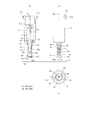
図11に示すように、本第2実施形態の押え部材81は、円板状の接触部82と、その上面側の円筒部83とを一体に有し、全体として浅底な有底円筒容器状をなす。円筒部83は、接触部82の外形よりも径小に形成されている。接触部82は、第1実施形態の接触部67と同様に、下面側で被切断物6に対して面接触する平坦面を有する。接触部82には、第1実施形態の貫通孔67aと同じ貫通孔82aが形成されている。
Second Embodiment
FIGS. 11 to 13 show a second embodiment of the present invention, and different points from the first embodiment will be described. In addition, the same code | symbol is attached | subjected to the same part as 1st Embodiment.
As shown in FIG. 11, the pressing member 81 of the second embodiment integrally has a disk-shaped contact portion 82 and a cylindrical portion 83 on the upper surface side thereof, and has a shallow bottomed cylindrical container as a whole. Shape. The cylindrical portion 83 is formed with a diameter smaller than the outer shape of the contact portion 82. The contact part 82 has a flat surface that makes surface contact with the workpiece 6 on the lower surface side, like the contact part 67 of the first embodiment. The contact portion 82 is formed with the same through hole 82a as the through hole 67a of the first embodiment.

ここで、図13(a)〜(c)では、カッタホルダ5の下降位置におけるカッタ4について、貫通孔82aからの刃先4bの突出量を、第1実施形態よりも若干増加させて示している。この場合でも、貫通孔82aは、カッタ4との係脱が可能な程度の隙間G2が確保されている(図13(b)参照)。また、この場合、押え部材81は、カッタホルダ5が上昇位置から下降位置に移動する際に、貫通孔67a内で刃先4bと係合する。このため、押え部材81は、前記切断開始点から、刃先4bと貫通孔67aとが接触した状態で被切断物6を押圧する。   Here, in FIGS. 13A to 13C, the protrusion amount of the blade edge 4b from the through hole 82a is slightly increased as compared with the first embodiment for the cutter 4 in the lowered position of the cutter holder 5. FIG. Even in this case, the through hole 82a has a gap G2 that can be engaged and disengaged with the cutter 4 (see FIG. 13B). In this case, the pressing member 81 is engaged with the blade edge 4b in the through hole 67a when the cutter holder 5 moves from the raised position to the lowered position. For this reason, the pressing member 81 presses the workpiece 6 while the cutting edge 4b and the through hole 67a are in contact with each other from the cutting start point.

図11(b)に示すように、本第2実施形態の嵌合支持部材85には、第1実施形態のバネ収容溝53aに代えて、外周部に第1段部86及び第2段部87が形成されている。嵌合支持部材85の第1段部86は、コイルバネ84の内側に嵌って、コイルバネ84を係止する。第2段部87は第1段部86よりも小さな外径寸法に設定されている。押え部材81の円筒部83は、第1段部86と同じ外径寸法に設定されており、コイルバネ84の内側に嵌って、コイルバネ84を係止する。即ち、コイルバネ84は、上端部が嵌合支持部材85の第1段部86の上端側に係止されると共に、下端部が押え部材81の円筒部83の下端側を係止する。換言すれば、押え部材81は、付勢部材としてのコイルバネ84を介して嵌合支持部材85に連結されている。上記のように、押え部材81は、嵌合支持部材85及びカッタ4並びにコイルバネ84と一体的に回動するように構成されている。また、押え部材81は、コイルバネ84の横方向への弾性変形により、貫通孔67aがカッタ4の刃先4bに接触する方向に移動が可能である。上記した押え部材81及びコイルバネ84は、本第2実施形態の押え装置88(押え手段)を構成する。   As shown in FIG. 11B, the fitting support member 85 of the second embodiment has a first step portion 86 and a second step portion on the outer peripheral portion instead of the spring accommodating groove 53a of the first embodiment. 87 is formed. The first step portion 86 of the fitting support member 85 is fitted inside the coil spring 84 to lock the coil spring 84. The second step portion 87 is set to have a smaller outer diameter than the first step portion 86. The cylindrical portion 83 of the pressing member 81 is set to have the same outer diameter as that of the first step portion 86 and fits inside the coil spring 84 to lock the coil spring 84. That is, the upper end portion of the coil spring 84 is locked to the upper end side of the first step portion 86 of the fitting support member 85, and the lower end portion is locked to the lower end side of the cylindrical portion 83 of the pressing member 81. In other words, the pressing member 81 is connected to the fitting support member 85 via the coil spring 84 as an urging member. As described above, the pressing member 81 is configured to rotate integrally with the fitting support member 85, the cutter 4, and the coil spring 84. Further, the holding member 81 can move in a direction in which the through hole 67 a contacts the blade edge 4 b of the cutter 4 by elastic deformation of the coil spring 84 in the lateral direction. The pressing member 81 and the coil spring 84 described above constitute the pressing device 88 (pressing means) of the second embodiment.

図11に示すように、カッタホルダ5の上昇位置において、カッタ4の刃先4bは、押え部材81から突出せず、コイルバネ84に囲われた状態にある。この状態で、Z軸モータ34を駆動させて、カッタホルダ5を下降位置へ移動させる。このとき、図12に示すように、カッタ4の刃先4bが被切断物6に到達する前に、押え部材81の接触部82が被切断物6と接触して、コイルバネ84が圧縮されることにより被切断物6に対する押圧力が作用する。そして、カッタ4の切先4aが接触部82の貫通孔67aから下方へ突出して被切断物6の切断開始点を貫通する際、押え部材81は、貫通孔67a内で刃先4bと係合する。これにより、カッタホルダ5の下降位置では、図13(b)(c)に示すように、押え部材81の中心軸線4zに対するずれ量D3が生じることとなり、切断開始点で、刃先4bと貫通孔67aが隙間無く接触した状態となる。従って、切断ラインLの切断開始点から切断終了点に至るまで、常に切先4a近傍で被切断物6を押圧した状態で切断を行うことができる。
一方、フィード時にカッタホルダ5全体が図12(b)の矢印方向に移動する場合、押え部材81は、接触部82と被切断物6と間に生じる摩擦力によって、第1実施形態と同様、刃先4bと貫通孔67aとが隙間なく接触する方向へずれる(同図の破線参照)。従って、フィード後における次の切断ラインLの切断時にも、常に刃先4b近傍で被切断物6を押圧した状態を維持することができる。
As shown in FIG. 11, at the raised position of the cutter holder 5, the cutting edge 4 b of the cutter 4 does not protrude from the pressing member 81 and is surrounded by the coil spring 84. In this state, the Z-axis motor 34 is driven to move the cutter holder 5 to the lowered position. At this time, as shown in FIG. 12, before the cutting edge 4b of the cutter 4 reaches the workpiece 6, the contact portion 82 of the pressing member 81 comes into contact with the workpiece 6 and the coil spring 84 is compressed. As a result, a pressing force acts on the workpiece 6. When the cutting edge 4a of the cutter 4 protrudes downward from the through hole 67a of the contact portion 82 and penetrates the cutting start point of the workpiece 6, the holding member 81 engages with the cutting edge 4b in the through hole 67a. . As a result, at the lowered position of the cutter holder 5, as shown in FIGS. 13B and 13C, a shift amount D3 with respect to the central axis 4z of the pressing member 81 is generated, and the cutting edge 4b and the through hole 67a are formed at the cutting start point. Will be in contact with no gap. Therefore, from the cutting start point of the cutting line L to the cutting end point, cutting can be performed with the workpiece 6 always pressed in the vicinity of the cutting edge 4a.
On the other hand, when the entire cutter holder 5 moves in the direction of the arrow in FIG. 12B during feeding, the presser member 81 has a cutting edge as in the first embodiment due to the frictional force generated between the contact portion 82 and the workpiece 6. 4b and the through-hole 67a shift | deviate to the direction which contacts without a gap (refer the broken line of the same figure). Therefore, even when cutting the next cutting line L after feeding, it is possible to always maintain a state in which the workpiece 6 is pressed in the vicinity of the cutting edge 4b.

尚、本発明は上記しかつ図面に示す実施形態にのみ限定されるものではなく、次のように変形または拡張することができる。本発明は、上記したカッティングプロッタとしての切断装置1に限られず、切断機能を備えた各種の装置に適用できるものである。
カッタは、先端部に刃先を有する構成であればよく、刃先の形状は略三角形状に限定するものではない。カッタの基部は、丸棒状のカッタ軸55に代えて平板状に形成してもよい。この場合、カッタに対して嵌合する嵌合支持部材を用いて平板状の基部を支持し、カッタを、嵌合支持部材を介して軸受手段により回動可能に支持することができる。支持手段は、カッタを刃先の向きの変更が可能に支持するものであればよく、刃先の向きを変更させるアクチュエータを備えた構成としてもよい。
The present invention is not limited to the embodiment described above and shown in the drawings, and can be modified or expanded as follows. The present invention is not limited to the cutting device 1 as the cutting plotter described above, and can be applied to various devices having a cutting function.
The cutter only needs to have a blade edge at the tip, and the shape of the blade edge is not limited to a substantially triangular shape. The base of the cutter may be formed in a flat plate shape in place of the round bar-shaped cutter shaft 55. In this case, the flat base portion can be supported by using a fitting support member fitted to the cutter, and the cutter can be rotatably supported by the bearing means via the fitting support member. The support means may be any means as long as it supports the cutter so that the direction of the blade edge can be changed, and may include an actuator that changes the direction of the blade edge.

押え手段の付勢部材は、上記したコイルバネ60,84に限定するものではなく、伸縮可能なベローズ状のゴム部材や、ウレタンフォームを用いて押え部材を被切断物6側へ付勢するように構成してもよい。また、押え部材の自重によって被切断物6を押圧するようにすれば、付勢部材は省略することもできる。また、押え手段は、切断手段と被切断物6との相対移動の際に、カッタの刃先の向きが変更されることに伴い、押え部材が当該刃先と連動して刃先近傍で押える位置を維持する駆動機構を備えた構成であってもよい。この構成においても、上記した実施形態と同様の効果を奏する。   The urging member of the pressing means is not limited to the coil springs 60 and 84 described above, and the pressing member is urged toward the workpiece 6 by using an expandable / contractible bellows-like rubber member or urethane foam. It may be configured. Further, if the workpiece 6 is pressed by its own weight, the urging member can be omitted. In addition, the presser means maintains the position where the presser member is pressed in the vicinity of the cutting edge in conjunction with the cutting edge as the direction of the cutting edge of the cutter is changed when the cutting means and the workpiece 6 are moved relative to each other. The structure provided with the drive mechanism to perform may be sufficient. Even in this configuration, the same effects as those of the above-described embodiment can be obtained.

1 切断装置
4 カッタ
4a 切先(刃先)
4b 刃先
4z 中心軸
5 切断手段(カッタホルダ)
6 被切断物
46 支持手段
47,88 押え手段
55 基部(カッタ軸)
60,84 付勢部材
61,81 押え部材
67,82 接触部
67a,82a 貫通孔
1 Cutting device 4 Cutter 4a Cutting edge (cutting edge)
4b Cutting edge 4z Center shaft 5 Cutting means (cutter holder)
6 Object 46 Support means 47, 88 Pressing means 55 Base (cutter shaft)
60, 84 Biasing member 61, 81 Presser member 67, 82 Contact part 67a, 82a Through hole

Claims (7)

切断手段と被切断物とを相対的に移動させることにより、前記被切断物から所望の模様を切断する切断装置であって、
前記切断手段は、
先端部に刃先を有するカッタと、
前記カッタを刃先の向きの変更が可能に支持する支持手段と、
前記カッタの刃先近傍で前記被切断物を押える押え部材を有し、前記切断手段と前記被切断物との相対移動の際に、前記カッタの刃先の向きが変更されることに伴い、前記押え部材が当該刃先と連動して前記刃先近傍で押える位置を維持するように構成された押え手段と、
を備えることを特徴とする切断装置。
A cutting device for cutting a desired pattern from the workpiece by relatively moving the cutting means and the workpiece,
The cutting means is
A cutter having a cutting edge at the tip,
Support means for supporting the cutter so that the orientation of the blade edge can be changed;
A presser member for pressing the workpiece in the vicinity of the cutter blade edge, and the presser blade is moved in accordance with a change in the orientation of the cutter blade edge during relative movement between the cutting means and the workpiece. Presser means configured to maintain a position where the member presses in the vicinity of the cutting edge in conjunction with the cutting edge;
A cutting apparatus comprising:
切断手段と被切断物とを相対的に移動させることにより、前記被切断物から所望の模様を切断する切断装置であって、
前記切断手段は、
一方向に延びる基部の中心軸に対して偏心した刃先を先端部に有するカッタと、
前記カッタを前記中心軸の回りに回動可能に支持する支持手段と、
前記カッタの刃先を囲うように形成され前記被切断物を押える押え部材を有し、前記切断手段と前記被切断物との相対移動の際に、前記カッタが前記中心軸の回りに回動して刃先の向きが変更されることに伴い、前記押え部材が当該刃先と連動して回動するように構成された押え手段と、
を備えることを特徴とする切断装置。
A cutting device for cutting a desired pattern from the workpiece by relatively moving the cutting means and the workpiece,
The cutting means is
A cutter having a cutting edge eccentric to the central axis of the base extending in one direction at the tip,
Support means for rotatably supporting the cutter around the central axis;
A presser member formed to surround the cutting edge of the cutter and pressing the workpiece; the cutter rotates about the central axis during relative movement between the cutting means and the workpiece; A presser means configured to rotate the presser member in conjunction with the cutting edge in accordance with the change of the direction of the cutting edge;
A cutting apparatus comprising:
前記押え手段は、前記押え部材を前記被切断物側へ付勢する付勢部材を備えることを特徴とする請求項1または2記載の切断装置。   The cutting apparatus according to claim 1 or 2, wherein the pressing means includes a biasing member that biases the pressing member toward the workpiece. 前記押え部材は、前記付勢部材を介して前記支持手段に連結されていることを特徴とする請求項3記載の切断装置。   The cutting device according to claim 3, wherein the pressing member is connected to the support means via the biasing member. 前記押え部材は、前記被切断物に接触する接触部と、前記接触部を前記カッタが延びる方向に貫通する貫通孔とを備え、前記貫通孔内で前記カッタの刃先側との係合が可能に構成されていることを特徴とする請求項1から4の何れかに記載の切断装置。   The pressing member includes a contact portion that contacts the workpiece and a through hole that penetrates the contact portion in a direction in which the cutter extends, and can be engaged with the blade edge side of the cutter in the through hole. The cutting device according to any one of claims 1 to 4, wherein the cutting device is configured as follows. 前記カッタは、前記刃先の先端ほど細くなる先細状に形成され、
前記貫通孔は、前記カッタの刃先側における前記カッタが延びる方向に対する垂直な断面と略相似形をなすことを特徴とする請求項5記載の切断装置。
The cutter is formed in a tapered shape that becomes thinner toward the tip of the blade edge,
6. The cutting apparatus according to claim 5, wherein the through-hole has a shape substantially similar to a cross section perpendicular to the direction in which the cutter extends on the blade edge side of the cutter.
前記押え部材は、前記カッタが延びる方向とは垂直な方向であって、前記刃先と前記貫通孔とが略隙間無く接触する方向に移動可能に前記付勢部材に保持されていることを特徴とする請求項6記載の切断装置。   The pressing member is held by the urging member so as to be movable in a direction perpendicular to a direction in which the cutter extends and in which the blade edge and the through hole are in contact with each other without a substantial gap. The cutting device according to claim 6.
JP2012065488A 2012-03-22 2012-03-22 Cutting device Pending JP2013193193A (en)

Priority Applications (2)

Application Number Priority Date Filing Date Title
JP2012065488A JP2013193193A (en) 2012-03-22 2012-03-22 Cutting device
US13/847,933 US20130276607A1 (en) 2012-03-22 2013-03-20 Cutting plotter

Applications Claiming Priority (1)

Application Number Priority Date Filing Date Title
JP2012065488A JP2013193193A (en) 2012-03-22 2012-03-22 Cutting device

Publications (1)

Publication Number Publication Date
JP2013193193A true JP2013193193A (en) 2013-09-30

Family

ID=49378890

Family Applications (1)

Application Number Title Priority Date Filing Date
JP2012065488A Pending JP2013193193A (en) 2012-03-22 2012-03-22 Cutting device

Country Status (2)

Country Link
US (1) US20130276607A1 (en)
JP (1) JP2013193193A (en)

Cited By (1)

* Cited by examiner, † Cited by third party
Publication number Priority date Publication date Assignee Title
JP2016068249A (en) * 2014-09-29 2016-05-09 元吉 許 Cutting tool

Families Citing this family (3)

* Cited by examiner, † Cited by third party
Publication number Priority date Publication date Assignee Title
JP2022184119A (en) * 2021-05-31 2022-12-13 株式会社ディスコ Sheet sticking apparatus
USD1017692S1 (en) * 2022-04-28 2024-03-12 Siser NA Cutter
CN115946173A (en) * 2022-12-09 2023-04-11 深圳爱多多智能装备科技有限公司 Imprinter

Citations (7)

* Cited by examiner, † Cited by third party
Publication number Priority date Publication date Assignee Title
JPS5074876A (en) * 1973-11-02 1975-06-19
JPS59124600A (en) * 1982-12-29 1984-07-18 ガ−バ−・ガ−メント・テクノロジ−・インコ−ポレ−テッド Method of preparing pattern piece
JPH06206192A (en) * 1993-01-13 1994-07-26 High Techno:Kk Cloth cutting device
JPH0717492U (en) * 1993-08-31 1995-03-28 ローランドディー.ジー.株式会社 Cutting pen
JPH07251599A (en) * 1994-03-15 1995-10-03 Roland D G Kk Sheet floating prevention mechanism
JPH0890486A (en) * 1994-09-28 1996-04-09 Roland D G Kk Cutting pen
US20080273951A1 (en) * 2007-05-04 2008-11-06 Stein Darryl C Fixturing Device for Holding Sheet Type Material

Family Cites Families (19)

* Cited by examiner, † Cited by third party
Publication number Priority date Publication date Assignee Title
US3477322A (en) * 1966-09-21 1969-11-11 Gerber Scientific Instr Co Device for cutting sheet material
US3548699A (en) * 1966-09-21 1970-12-22 Heinz Joseph Gerber Device for cutting sheet material
CH1805771A4 (en) * 1970-02-09 1973-02-15
US4358979A (en) * 1980-11-24 1982-11-16 Exxon Research & Engineering Co. Apparatus for cutting plastic film
US4674503A (en) * 1981-03-05 1987-06-23 Peyman Gholam A Controlled depth penetrant apparatus and method
US4841822A (en) * 1986-05-08 1989-06-27 Gerber Scientific, Inc. Cutter head and knife for cutting sheet material
US4934236A (en) * 1988-11-07 1990-06-19 Am International Corporation Sheet slicing mechanism
US5094134A (en) * 1990-06-08 1992-03-10 Roland Dg Corporation Cutting pen
US5143576A (en) * 1990-08-10 1992-09-01 Gerber Scientific Products, Inc. Automatic weeding system and method of use
JPH04257367A (en) * 1991-02-06 1992-09-11 Janome Sewing Mach Co Ltd Mark cutting device and its control
US5376099A (en) * 1992-09-17 1994-12-27 Kmi, Inc. Undercut diamond surgical blade and method of using the same
GB9314390D0 (en) * 1993-07-12 1993-08-25 Esselte Dymo Nv Tape cutting apparatus
JP4048658B2 (en) * 1999-09-16 2008-02-20 ブラザー工業株式会社 Label manufacturing apparatus and label manufacturing method
WO2002083335A1 (en) * 2001-04-11 2002-10-24 Solidimension Ltd. Method and apparatus to reduce deformation in sheets cut by a cutting tool
US7054708B1 (en) * 2003-11-05 2006-05-30 Xyron, Inc. Sheet material cutting system and methods regarding same
US8156852B2 (en) * 2004-01-22 2012-04-17 Graphtec Kabushiki Kaisha Cutting plotter, cutting plotter driving control device, cut target medium supporting sheet, cut target medium, cutting pen, method of manufacturing paper product, and method of generating cut data
WO2006055408A2 (en) * 2004-11-15 2006-05-26 Xyron, Inc. Automatic pattern making apparatus
US20070227332A1 (en) * 2004-11-15 2007-10-04 Xyron, Inc. Automatic pattern making apparatus
US7930958B2 (en) * 2005-07-14 2011-04-26 Provo Craft And Novelty, Inc. Blade housing for electronic cutting apparatus

Patent Citations (7)

* Cited by examiner, † Cited by third party
Publication number Priority date Publication date Assignee Title
JPS5074876A (en) * 1973-11-02 1975-06-19
JPS59124600A (en) * 1982-12-29 1984-07-18 ガ−バ−・ガ−メント・テクノロジ−・インコ−ポレ−テッド Method of preparing pattern piece
JPH06206192A (en) * 1993-01-13 1994-07-26 High Techno:Kk Cloth cutting device
JPH0717492U (en) * 1993-08-31 1995-03-28 ローランドディー.ジー.株式会社 Cutting pen
JPH07251599A (en) * 1994-03-15 1995-10-03 Roland D G Kk Sheet floating prevention mechanism
JPH0890486A (en) * 1994-09-28 1996-04-09 Roland D G Kk Cutting pen
US20080273951A1 (en) * 2007-05-04 2008-11-06 Stein Darryl C Fixturing Device for Holding Sheet Type Material

Cited By (8)

* Cited by examiner, † Cited by third party
Publication number Priority date Publication date Assignee Title
JP2016068249A (en) * 2014-09-29 2016-05-09 元吉 許 Cutting tool
TWI593533B (en) * 2014-09-29 2017-08-01 許元吉 Cutting tool
JP2017159447A (en) * 2014-09-29 2017-09-14 元吉 許 Cutting tool
US9969097B2 (en) 2014-09-29 2018-05-15 Yuan-Chi Hsu Cutting tool
JP2019051590A (en) * 2014-09-29 2019-04-04 元吉 許 Cutting tool
JP2019069513A (en) * 2014-09-29 2019-05-09 元吉 許 Cutting tool
US10456942B2 (en) 2014-09-29 2019-10-29 Yuan-Chi Hsu Cutting method
USRE48804E1 (en) 2014-09-29 2021-11-02 Yuan-Chi Hsu Cutting tool

Also Published As

Publication number Publication date
US20130276607A1 (en) 2013-10-24

Similar Documents

Publication Publication Date Title
JP2013193193A (en) Cutting device
US8855802B2 (en) Cutting apparatus, cutting data processing device and cutting control program therefor
US9193082B2 (en) Cutting plotter and non-transitory computer-readable storage medium
US7819599B2 (en) Cutting device for tape printing apparatus
JP6069907B2 (en) Cutting device and control program for cutting device
US20120247293A1 (en) Cutting apparatus, holding member for holding object to be cut and storage medium storing cutting control program
JP6094178B2 (en) Cutting device
US9827687B2 (en) Cutting apparatus and cutting control program therefor
JP2016032847A (en) Cutting device, and cutting data creation program
JP2014108464A (en) Cutter cartridge and cutting device
JP5842418B2 (en) Cutting device, cutting data processing device, and cutting data processing program
EP3848218A1 (en) Display device for vehicle
JP2012206237A (en) Cutting apparatus, cutting data processing device and program, and recording medium
JP2019177447A (en) Cutting device
JP7314688B2 (en) cutting device
JP2014189938A (en) Sewing machine and sewing machine sewing operation control program
JP5382043B2 (en) Cutting device, cutting data processing device, cutting data processing program and recording medium
US9156176B2 (en) Cutting apparatus and computer readable storage medium
JP2013091133A (en) Cutting apparatus
US20130180373A1 (en) Cutting plotter and non-transitory computer-readable medium
JP2011055887A (en) Workpiece holder and sewing machine
JP2015024482A (en) Cutting device and record medium recording processing program
US20120253503A1 (en) Cutting apparatus and storage medium storing cutting control program
JP2014128836A (en) Cutting device, holding member, and cutting member
JP2013193192A (en) Cutting device

Legal Events

Date Code Title Description
A621 Written request for application examination

Free format text: JAPANESE INTERMEDIATE CODE: A621

Effective date: 20141105

A977 Report on retrieval

Free format text: JAPANESE INTERMEDIATE CODE: A971007

Effective date: 20151118

A131 Notification of reasons for refusal

Free format text: JAPANESE INTERMEDIATE CODE: A131

Effective date: 20151124

A02 Decision of refusal

Free format text: JAPANESE INTERMEDIATE CODE: A02

Effective date: 20160322