JP2013190712A - Manufacturing method of optical lens - Google Patents
Manufacturing method of optical lens Download PDFInfo
- Publication number
- JP2013190712A JP2013190712A JP2012058130A JP2012058130A JP2013190712A JP 2013190712 A JP2013190712 A JP 2013190712A JP 2012058130 A JP2012058130 A JP 2012058130A JP 2012058130 A JP2012058130 A JP 2012058130A JP 2013190712 A JP2013190712 A JP 2013190712A
- Authority
- JP
- Japan
- Prior art keywords
- lens
- hard coat
- pulling
- group
- coat film
- Prior art date
- Legal status (The legal status is an assumption and is not a legal conclusion. Google has not performed a legal analysis and makes no representation as to the accuracy of the status listed.)
- Pending
Links
Images


Abstract
Description
本発明は、光学レンズの製造方法に関し、特にはディッピング法によって厚膜化したハードコート膜の形成が可能な光学レンズの製造方法に関する。 The present invention relates to an optical lens manufacturing method, and more particularly to an optical lens manufacturing method capable of forming a hard coat film thickened by a dipping method.
眼鏡のユーザーにとって、レンズ表面にキズが入るリスクは常に付いて回る問題である。レンズへのキズは何らかの物体の衝突や摩擦によって生じるものが多数であり、それを防ぐ目的で、多くの眼鏡レンズには有機のハードコート膜と無機の反射防止膜が施されている。このうちハードコート膜は、レンズ基材よりも硬い膜であり、キズを防止する作用を持つほか、その上の反射防止膜との密着性を持たせる中間層としての作用も担っている。また、反射防止膜は、ハードコート膜よりもさらに硬度の高い無機の多層膜が用いられることが多く、反射光の映り込みを防ぐ従来の作用に加えて、キズを防止する作用が付加されるようになってきた。 For eyeglass users, the risk of scratching the lens surface is always a problem. Many scratches on the lens are caused by collision or friction of an object, and for the purpose of preventing this, many spectacle lenses are provided with an organic hard coat film and an inorganic antireflection film. Among these, the hard coat film is a film harder than the lens substrate, and has an effect of preventing scratches, and also acts as an intermediate layer for providing adhesion to the antireflection film thereon. In addition, the antireflection film is often an inorganic multilayer film having a higher hardness than the hard coat film, and in addition to the conventional action of preventing reflection of reflected light, the action of preventing scratches is added. It has become like this.
ところで、レンズ基材上にハードコート膜を形成する際には、ディッピング法、スピン法、スプレー法といった塗布方法が一般的に用いられている。ディッピング法は、ハードコート液にプラスチックレンズを浸漬させたのちに引き上げていく手法である。スピン法はハードコート液をプラスチックレンズ上に滴下しつつ、プラスチックレンズを回転させることにより、ハードコート膜を均一に塗り広げる手法である。スプレー法は、スプレーノズルからハードコート液をプラスチックレンズに噴射して塗布する手法である。 By the way, when forming a hard coat film on a lens substrate, coating methods such as a dipping method, a spin method, and a spray method are generally used. The dipping method is a method in which a plastic lens is immersed in a hard coat solution and then pulled up. The spin method is a method of spreading the hard coat film uniformly by rotating the plastic lens while dripping the hard coat solution onto the plastic lens. The spray method is a method in which a hard coat liquid is sprayed onto a plastic lens from a spray nozzle.
このうち特にディッピング法は、最も簡便な方法であり、引き上げ速度を10〜1000mm/minの範囲で調整することにより、均一性の良好なハードコート膜が形成されるとしている(下記特許文献1参照)。 Of these, the dipping method is the simplest method, and a hard coat film with good uniformity is formed by adjusting the pulling rate within a range of 10 to 1000 mm / min (see Patent Document 1 below). ).
しかしながら、以上のようなディッピング法によって形成されるハードコート膜の膜厚は、2〜3μm程度でしかなく、さらに膜厚の大きいハードコート膜を形成することが困難であった。これに対して、スピン法では数μm〜数10μm、スプレー法では数10μm〜数100μmの膜厚のハードコート膜を形成することが可能ではあるが、膜厚分布の管理が難しいという問題があった。 However, the thickness of the hard coat film formed by the dipping method as described above is only about 2 to 3 μm, and it is difficult to form a hard coat film having a larger thickness. On the other hand, although it is possible to form a hard coat film having a film thickness of several μm to several tens of μm by the spin method and several tens μm to several hundred μm by the spray method, there is a problem that it is difficult to manage the film thickness distribution. It was.
そこで本発明は、厚膜でありながらも膜厚分布が均等なハードコート膜をレンズ基材上に形成することが可能な光学レンズの製造方法を提供することを目的とする。 Accordingly, an object of the present invention is to provide a method of manufacturing an optical lens that can form a hard coat film having a uniform film thickness distribution on a lens substrate while being a thick film.
このような目的を達成するための本発明は、塗布液中にレンズ基材を浸漬する浸漬工程と、この塗布液から前記レンズ基材が露出を開始してから完全に露出するまでの間に、引き上げ速度を減速する期間を設けて当該塗布液中から当該レンズ基材を引き上げる引き上げ工程と、レンズ基材の表面に塗布された塗布液を硬化処理してハードコート膜を形成する硬化処理工程と、ハードコート膜が所定膜厚となるまで、以上の浸漬工程〜引き上げ工程〜硬化処理工程を複数回繰り返すことを判断する判断工程とを備えて光学レンズの製造方法である。 In order to achieve such an object, the present invention provides a dipping step of immersing a lens substrate in a coating solution and a period from the start of exposure of the lens substrate to the complete exposure from the coating solution. , A lifting step for raising the lens base material from the coating liquid by providing a period for slowing the lifting speed, and a curing process step for curing the coating liquid applied to the surface of the lens base material to form a hard coat film And a determination step of determining that the above immersion step, the pulling step, and the curing treatment step are repeated a plurality of times until the hard coat film has a predetermined thickness.
このような製造方法によれば、塗布液からレンズ基材を引き上げる際に、引き上げ速度を減速させる期間を設けた引き上げ工程を行うことにより、後の実施例で説明するように、ハードコート膜の膜厚のレンズ面内における均一性が確保されることがわかった。そして、塗布液の硬化処理工程を挟んで、このような引き上げを繰り返し行うことで、面内均一性の高いハードコート膜が重ね塗りされ、膜厚の均一性の高いハードコート膜を厚膜化することが可能になる。 According to such a manufacturing method, when the lens base material is lifted from the coating liquid, by performing a pulling step provided with a period for decelerating the pulling speed, as described in a later example, It was found that the uniformity of the film thickness within the lens surface was ensured. And by repeatedly performing such pulling up across the curing process of the coating liquid, a hard coat film with high in-plane uniformity is overcoated, and a hard coat film with high film thickness uniformity is made thicker It becomes possible to do.
以上のような浸漬工程〜硬化処理工程は、レンズ基材のレンズ面を略垂直に保持した状態で行われる。 The immersion process to the curing process as described above are performed in a state where the lens surface of the lens substrate is held substantially vertically.
また繰り返し行われる引き上げ工程では、レンズ基材の周縁に設定した同一の一端部を上端として当該レンズ基材を引き上げる。これにより、レンズ基材を保持する保持具からの液だれが防止され、レンズ基材の周縁にまでわたる全面において、膜厚の均一なハードコート膜が得られる。 In the repeated pulling process, the lens base is pulled up with the same one end set at the periphery of the lens base as the upper end. Thereby, dripping from the holder holding the lens base material is prevented, and a hard coat film having a uniform film thickness is obtained on the entire surface extending to the periphery of the lens base material.
さらに、各引き上げ工程では、塗布液からレンズ基材が露出を開始した直後、および当該レンズ基材が露出を終了する直前の少なくとも一方において、当該レンズ基材の引き上げ速度を一定にする。これにより、後の実施例で説明するように、ハードコート膜の膜厚のレンズ面内における面内均一性を高めることができる。 Further, in each pulling step, the pulling speed of the lens base material is made constant at least one immediately after the lens base material starts to be exposed from the coating liquid and immediately before the lens base material ends the exposure. Thereby, the in-plane uniformity in the lens surface of the film thickness of the hard coat film can be improved as will be described in a later example.
また判断工程は、引き上げ工程と硬化処理工程との間に行われ、この判断工程においてハードコート膜が所定膜厚となったと判断された後の硬化処理工程では、塗布液を完全に硬化させるために前回までとは異なる条件での硬化処理を行う。 In addition, the determination process is performed between the pulling process and the curing process, and in the determination process, it is determined that the hard coat film has reached a predetermined film thickness in order to completely cure the coating liquid. The curing process is performed under conditions different from the previous one.
以上説明したように本発明の光学レンズの製造方法によれば、厚膜でありながらも膜厚分布が均等なハードコート膜をレンズ基材上に形成することが可能となる。 As described above, according to the method for manufacturing an optical lens of the present invention, it is possible to form a hard coat film having a uniform film thickness distribution on a lens substrate while being a thick film.
以下、本発明に係る光学レンズの製造方法の一実施形態を、図面に基づいて説明する。尚、本実施形態においては、本発明をレンズ基材上にハードコート膜を形成する手順に適用した構成を説明するが、本発明の適用がこれに限定されることはなく、レンズ基材上に各種の光学膜(例えばハードコート膜)をある程度に厚膜化して形成する場合に広く適用可能である。 Hereinafter, an embodiment of a method for producing an optical lens according to the present invention will be described with reference to the drawings. In the present embodiment, a configuration in which the present invention is applied to a procedure for forming a hard coat film on a lens substrate will be described. However, the application of the present invention is not limited to this, and the present invention is not limited to this. In addition, the present invention can be widely applied when various optical films (for example, hard coat films) are formed to a certain degree of thickness.
図1は、本発明に係る光学レンズの製造方法の一実施形態を示すフローチャートであり、図2、図3は本発明に係る光学レンズの製造方法の一実施形態を説明するための模式図である。先ず、図1のフローチャートに沿って、図2、図3を参照しつつ、実施形態の光学レンズの製造方法を説明する。 FIG. 1 is a flowchart showing an embodiment of a method for manufacturing an optical lens according to the present invention, and FIGS. 2 and 3 are schematic diagrams for explaining an embodiment of a method for manufacturing an optical lens according to the present invention. is there. First, according to the flowchart of FIG. 1, the manufacturing method of the optical lens of embodiment is demonstrated, referring FIG. 2, FIG.
≪プライマー層の形成(S1)≫
先ずレンズ基材の表面にプライマー層を形成する(S1)。ここではレンズ基材として、以下に示すプラスチック材料で構成されたプラスチックレンズを用いる。このようなレンズ基材上に設けるプライマー層は、レンズ基材における耐衝撃性を確保すると共に、次にレンズ基材上に設けるハードコート膜とレンズ基材との間の密着性を確保するためのものである。またプライマー層は、レンズ基材を比較的高屈折率材料より構成する場合は、光学特性に影響を及ぼさない材料で構成されれば良い。
<< Formation of primer layer (S1) >>
First, a primer layer is formed on the surface of the lens substrate (S1). Here, a plastic lens made of a plastic material shown below is used as the lens substrate. The primer layer provided on such a lens base material ensures the impact resistance of the lens base material, and in addition, ensures the adhesion between the hard coat film provided on the lens base material and the lens base material. belongs to. The primer layer may be made of a material that does not affect the optical characteristics when the lens substrate is made of a relatively high refractive index material.
このようなプライマー層の形成方法としては、ディッピング法やスピンコート法、スプレー法等により塗布した後、加熱や光線照射等により硬化して形成することができる。 As a method for forming such a primer layer, it can be formed by applying a dipping method, a spin coat method, a spray method or the like and then curing it by heating, light irradiation or the like.
[レンズ基材]
レンズ基材を構成するプラスチック材料としては、以下の材料を用いることができる。例えばメチルメタクリレート単独重合体、メチルメタクリレートと一種以上の他のモノマーとをモノマー成分とする共重合体、ジエチレングリコールビスアリルカーボネート単独重合体、ジエチレングリコールビスアリルカーボネートと一種以上の他のモノマーとをモノマー成分とする共重合体、イオウ含有共重合体、ハロゲン含有共重合体、ポリカーボネート、ポリスチレン、ポリ塩化ビニル、不飽和ポリエステル、ポリエチレンテレフタレート、ポリウレタン、ポリチオウレタン、スルフィド結合を有するモノマーの単独重合体、スルフィドと一種以上の他のモノマーとをモノマー成分とする共重合体、ポリスルフィドと一種以上の他のモノマーとをモノマー成分とする共重合体、ポリジスルフィドと一種以上の他のモノマーとをモノマー成分とする共重合体等である。また、レンズ基材の材料として、屈折率が1.6以上程度の比較的高屈折率な材料を用いても良い。
[Lens substrate]
The following materials can be used as the plastic material constituting the lens substrate. For example, methyl methacrylate homopolymer, copolymer having methyl methacrylate and one or more other monomers as monomer components, diethylene glycol bisallyl carbonate homopolymer, diethylene glycol bisallyl carbonate and one or more other monomers as monomer components Copolymer, sulfur-containing copolymer, halogen-containing copolymer, polycarbonate, polystyrene, polyvinyl chloride, unsaturated polyester, polyethylene terephthalate, polyurethane, polythiourethane, homopolymer of monomer having sulfide bond, sulfide and Copolymers containing one or more other monomers as monomer components, copolymers containing polysulfides and one or more other monomers as monomer components, polydisulfides and one or more other monomers as monomers A copolymer such as a component. Further, as a material for the lens substrate, a relatively high refractive index material having a refractive index of about 1.6 or more may be used.
尚、このようなプライマー層形成工程は、必要に応じて行えば良く、必要ない場合には省略しても良い。 Such a primer layer forming step may be performed as necessary, and may be omitted if not necessary.
≪ハードコート膜の形成(S2)≫
次にレンズ基材の表面に、プライマー層を介してハードコート膜を形成する(S2)。ハードコート膜の形成は、通常、ディッピング法、スピンコート法、スプレー法等の塗布法が適用されるが、ここではディッピング法によるハードコート膜の形成を行い、次の手順でハードコート膜を形成する。
<< Formation of hard coat film (S2) >>
Next, a hard coat film is formed on the surface of the lens substrate via a primer layer (S2). The hard coat film is usually formed by a coating method such as dipping, spin coating, or spraying. Here, the hard coat film is formed by the dipping method, and the hard coat film is formed by the following procedure. To do.
<浸漬工程(S21)>
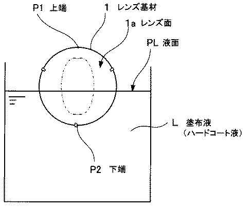
まず、塗布液中にレンズ基材を浸漬する浸漬工程(S21)を行う。ここで用いる塗布液は、以降で詳細に説明するように、ハードコート膜を形成するための形成材料を含むハードコート液である。ここでは図2に示すように、この塗布液L中に、レンズ基材1の全体を完全に浸漬し、レンズ基材1の全体が塗布液Lの液面PLよりも下となるようにする。この際、塗布液L中のレンズ基材1は、例えば液面PLに対してレンズ面1aが略垂直となるように保持されていることとする。
<Immersion process (S21)>
First, an immersion step (S21) in which the lens substrate is immersed in the coating solution is performed. The coating liquid used here is a hard coat liquid containing a forming material for forming a hard coat film, as will be described in detail later. Here, as shown in FIG. 2, the entire lens base material 1 is completely immersed in the coating liquid L so that the entire lens base material 1 is below the liquid level PL of the coating liquid L. . At this time, the lens substrate 1 in the coating liquid L is held, for example, so that the lens surface 1a is substantially perpendicular to the liquid level PL.
以上のようなレンズ基材1の保持は、レンズ基材1をその外周部分で挟持する保持部材3によって行われる。この保持部材3は、例えばレンズ基材1の外周の3箇所に、ほぼ均等な間隔を設けて配置され、この3箇所においてレンズ基材1を保持している。ここでの図示は省略したが、これらの保持部材3は、塗布液Lの液面に対して保持部材3を上下動可能なアームに固定され、このアームの上下動によって保持部材3に保持されたレンズ基材1の塗布液Lへの浸漬と引き上げが自在に行われる構成となっている。
The lens substrate 1 is held by the
またレンズ基材1は、このような保持部材3への固定により、レンズ基材1の周縁の一端部が上端P1となり、反対側の一端部が下端P2となるように保持される。そして、レンズ基材1の下端P2付近が1つの保持部材3で保持され、このレンズ基材1の両側が2つの保持部材3で保持された状態となっている。レンズ基材1の両側を保持する保持部材3は、レンズ基材1の中央に設定されたレンズ領域Aを外した位置、すなわちレンズ領域Aを垂直方向に延設した領域の外側において、レンズ基材1を保持していることとする。これにより、保持部材3からの液だれの影響がレンズ領域Aに及ばない構成となっている。
The lens base 1 is held by such fixing to the holding
[塗布液]
塗布液L(すなわちハードコート液)は、有機ケイ素化合物、いわゆるシランカップリング材や有機エポキシ材といった有機高分子を主剤とし、さらにレンズ基材1との屈折率を合わせる目的で、酸化スズやジルコニアなどの金属酸化物を含有している。このような塗布液Lは、例えば酸化スズゾルあるいはジルコニアゾルに、有機ケイ素化合物を1種以上と、さらに他の金属酸化物や触媒を含む。
[Coating solution]
The coating liquid L (that is, hard coat liquid) is mainly composed of an organic polymer such as an organic silicon compound, so-called silane coupling material or organic epoxy material, and tin oxide or zirconia for the purpose of matching the refractive index with the lens substrate 1. It contains metal oxides such as Such a coating liquid L contains, for example, tin oxide sol or zirconia sol, one or more organic silicon compounds, and further another metal oxide or catalyst.
例えば塗布液(ハードコート液)として酸化スズゾルを用いた場合、この塗布液には、さらに他の金属酸化物、有機ケイ素化合物、さらにはレンズ基材上に塗布した塗布液の硬化反応を促進するための硬化触媒、レンズ基材への塗布時の濡れ性を向上させ平滑性を向上させるための有機溶剤や界面活性剤(レベリング剤)を含有させることもできる。さらに、紫外線吸収剤、酸化防止剤、光安定剤等もハードコート膜の物性に影響を与えない限り添加することができる。このような塗布液Lに含有させる各材料は、以下の通りである。 For example, when a tin oxide sol is used as a coating solution (hard coating solution), the coating solution further accelerates the curing reaction of other metal oxides, organosilicon compounds, and coating solutions coated on a lens substrate. In order to improve the wettability at the time of application | coating to the lens base material and a lens base material, and to improve smoothness, surfactant and a surfactant (leveling agent) can also be contained. Furthermore, ultraviolet absorbers, antioxidants, light stabilizers and the like can be added as long as they do not affect the physical properties of the hard coat film. Each material contained in the coating liquid L is as follows.
[金属酸化物]
金属酸化物としては、アルミニウム(Al)、アンチモン(Sb)、シリコン(Si)、セリウム(Ce)、鉄(Fe)、インジウム(In)、亜鉛(Zn)、チタン(Ti)、ジルコニウム(Zr)等の金属のうちの1種以上の酸化物、複合酸化物が挙げられる。
[Metal oxide]
Examples of metal oxides include aluminum (Al), antimony (Sb), silicon (Si), cerium (Ce), iron (Fe), indium (In), zinc (Zn), titanium (Ti), and zirconium (Zr). One or more oxides or composite oxides of metals such as
これらの金属酸化物は、溶媒に分散させた状態で、塗布液に対して添加されていることとする。金属酸化物を分散させる溶媒としては、メタノール、エタノール、イソプロパノール等のアルコール類、プロピレングリコールモノメチルエーテル、プロピレングリコールモノエチルエーテル、プロピレングリコールモノブチルエーテル、プロピレングリコールプロピルエーテル、エチレングリコールモノメチルエーテル、エチレングリコールモノエチルエーテル、エチレングリコールモノブチルエーテル等のグリコールエーテル類、エチレングリコール、ジエチレングリコール、トリエチレングリコール、プロピレングリコール等のグリコール類、メチルエチルケトン、メチルイソブチルケトン等のケトン類等公知の原料を用いることができる。 These metal oxides are added to the coating solution in a state dispersed in a solvent. Solvents for dispersing the metal oxide include alcohols such as methanol, ethanol and isopropanol, propylene glycol monomethyl ether, propylene glycol monoethyl ether, propylene glycol monobutyl ether, propylene glycol propyl ether, ethylene glycol monomethyl ether, ethylene glycol monoethyl Known materials such as ethers, glycol ethers such as ethylene glycol monobutyl ether, glycols such as ethylene glycol, diethylene glycol, triethylene glycol and propylene glycol, and ketones such as methyl ethyl ketone and methyl isobutyl ketone can be used.
[有機ケイ素化合物]
有機ケイ素化合物としては、アミノ系、イソシアネート系、エポキシ系、アクリル系、ビニル系、メタクリル系、スチリル系、ウレイド系、メルカプト系のシランカップリング剤からなる群から選ばれる少なくとも1種以上を用いる場合に好適である。例えば、下記一般式(1)で表わされる有機ケイ素化合物、および下記一般式(2)で表わされる有機ケイ素化合物及びそれらの加水分解物の中から選ばれる少なくとも一種を用いることができる。
[Organic silicon compound]
When using at least one selected from the group consisting of amino, isocyanate, epoxy, acrylic, vinyl, methacrylic, styryl, ureido, and mercapto silane coupling agents as the organosilicon compound It is suitable for. For example, at least one selected from an organosilicon compound represented by the following general formula (1), an organosilicon compound represented by the following general formula (2), and a hydrolyzate thereof can be used.
(R1)nSi(OR2)4-n・・・一般式(1) (R 1 ) n Si (OR 2 ) 4-n ... General formula (1)
一般式(1)において、R1は官能基(アミノ基・イソシアネート基・エポキシ基・アクリル基・ビニル基・メタクリル基・スチリル基・ウレイド基・メルカプト基)を有する1価の炭素数3〜20の炭化水素基であり、例えばγ−アミノプロピル基、N−β(アミノエチル)−γ−アミノプロピル基、N−フェニル−γ−アミノプロピル基、γ−イソシアネートプロピル基、γ−グリシドキシプロピル基、β−エポキシシクロヘキシルエチル基、γ−アクリロキシプロピル基、ビニル基、γ−メタクリロキシプロピル基、p−スチリル基、γ−ウレイドプロピル基、γ−メルカプトプロピル基などが挙げられる。 In the general formula (1), R 1 is a monovalent carbon number of 3 to 20 having a functional group (amino group, isocyanate group, epoxy group, acrylic group, vinyl group, methacryl group, styryl group, ureido group, mercapto group). For example, γ-aminopropyl group, N-β (aminoethyl) -γ-aminopropyl group, N-phenyl-γ-aminopropyl group, γ-isocyanatepropyl group, γ-glycidoxypropyl Group, β-epoxycyclohexylethyl group, γ-acryloxypropyl group, vinyl group, γ-methacryloxypropyl group, p-styryl group, γ-ureidopropyl group, γ-mercaptopropyl group and the like.
また一般式(1)においてR2は炭素数1〜8のアルキル基、炭素数6〜10のアリール基、炭素数7〜10のアラルキル基、又は炭素数2〜10のアシル基である。前記R2の炭素数1〜8のアルキル基は、直鎖状、分岐状、環状のいずれであってもよく、例えばメチル基、エチル基、n−プロピル基、イソプロピル基、n−ブチル基、イソブチル基、sec−ブチル基、tert−ブチル基、ペンチル基、ヘキシル基、シクロペンチル基、シクロヘキシル基などが挙げられる。アリール基としては、例えば、フェニル基、トリル基などが挙げられ、アラルキル基としては、例えば、ベンジル基、フェネチル基などが挙げられ、アシル基としては、例えばアセチル基などが挙げられる。 In General Formula (1), R 2 is an alkyl group having 1 to 8 carbon atoms, an aryl group having 6 to 10 carbon atoms, an aralkyl group having 7 to 10 carbon atoms, or an acyl group having 2 to 10 carbon atoms. The alkyl group having 1 to 8 carbon atoms of R 2 may be linear, branched or cyclic, for example, methyl group, ethyl group, n-propyl group, isopropyl group, n-butyl group, Examples include isobutyl group, sec-butyl group, tert-butyl group, pentyl group, hexyl group, cyclopentyl group, cyclohexyl group and the like. Examples of the aryl group include a phenyl group and a tolyl group. Examples of the aralkyl group include a benzyl group and a phenethyl group. Examples of the acyl group include an acetyl group.
一般式(1)において、nは1又は2の整数を示し、R1が複数ある場合には複数のR1はたがいに同一でも異なっていてもよく、複数のOR2はたがいに同一でも異なっていてもよい。 In formula (1), n represents an integer of 1 or 2, a plurality of R 1 if R 1 is more may be the same with or different from each other, a plurality of OR 2 are the same as or different from each other It may be.
一般式(1)で表わされる有機ケイ素化合物の具体例としては、γ−アミノプロピルトリメトキシシラン、γ−アミノプロピルジメトキシメチルシラン、γ−アミノプロピルトリエトキシシラン、γ−アミノプロピルジエトキシメチルシラン、N−β(アミノエチル)γ−アミノプロピルジメトキシメチルシラン、N−β(アミノエチル)γ−アミノプロピルトリメトキシシラン、N−β(アミノエチル)γ−アミノプロピルトリエトキシシラン、N−β(アミノエチル)γ−アミノプロピルジエトキシメチルシラン、N−フェニル−γ−アミノプロピルトリメトキシシラン、N−フェニル−γ−アミノプロピルジメトキシメチルシラン、N−フェニル−γ−アミノプロピルトリエトキシシラン、N−フェニル−γ−アミノプロピルジエトキシメチルシラン、γ−イソシアネートプロピルトリメトキシシラン、γ−イソシアネートプロピルジメトキシメチルシラン、γ−イソシアネートプロピルトリエトキシシラン、γ−イソシアネートプロピルジエトキシメチルシラン、γ−グリシドキシプロピルトリメトキシシラン、γ−グリシドキシプロピルジメトキシメチルシラン、γ−グリシドキシプロピルトリエトキシシラン、γ−グリシドキシプロピルジエトキシメチルシラン、β−エポキシシクロヘキシルエチルトリメトキシシラン、β−エポキシシクロヘキシルエチルジメトキシメチルシラン、β−エポキシシクロヘキシルエチルトリエトキシシラン、β−エポキシシクロヘキシルエチルジエトキシメチルシラン、γ−アクリロキシプロピルトリメトキシシラン、γ−アクリロキシプロピルジメトキシメチルシラン、γ−アクリロキシプロピルトリエトキシシラン、γ−アクリロキシプロピルジエトキシメチルシラン、ビニルトリメトキシシラン、ビニルジメトキシメチルシラン、ビニルトリエトキシシラン、ビニルジエトキシメチルシラン、γ−メタクリロキシプロピルトリメトキシシラン、γ−メタクリロキシプロピルジメトキシメチルシラン、γ−メタクリロキシプロピルトリエトキシシラン、γ−メタクリロキシプロピルジエトキシメチルシラン、p−スチリルトリメトキシシラン、p−スチリルジメトキシメチルシラン、p−スチリルトリエトキシシラン、p−スチリルジエトキシメチルシラン、γ−ウレイドプロピルトリメトキシシラン、γ−ウレイドプロピルジメトキシメチルシラン、γ−ウレイドプロピルトリエトキシシラン、γ−ウレイドプロピルジエトキシメチルシラン、γ−メルカプトプロピルトリメトキシシラン、γ−メルカプトプロピルジメトキシメチルシラン、γ−メルカプトプロピルトリエトキシシラン、γ−メルカプトプロピルジエトキシメチルシラン等が挙げられる。 Specific examples of the organosilicon compound represented by the general formula (1) include γ-aminopropyltrimethoxysilane, γ-aminopropyldimethoxymethylsilane, γ-aminopropyltriethoxysilane, γ-aminopropyldiethoxymethylsilane, N-β (aminoethyl) γ-aminopropyldimethoxymethylsilane, N-β (aminoethyl) γ-aminopropyltrimethoxysilane, N-β (aminoethyl) γ-aminopropyltriethoxysilane, N-β (amino Ethyl) γ-aminopropyldiethoxymethylsilane, N-phenyl-γ-aminopropyltrimethoxysilane, N-phenyl-γ-aminopropyldimethoxymethylsilane, N-phenyl-γ-aminopropyltriethoxysilane, N-phenyl -Γ-aminopropyldiethoxymethyl , Γ-isocyanatopropyltrimethoxysilane, γ-isocyanatopropyldimethoxymethylsilane, γ-isocyanatopropyltriethoxysilane, γ-isocyanatopropyldiethoxymethylsilane, γ-glycidoxypropyltrimethoxysilane, γ-glycidoxy Propyldimethoxymethylsilane, γ-glycidoxypropyltriethoxysilane, γ-glycidoxypropyldiethoxymethylsilane, β-epoxycyclohexylethyltrimethoxysilane, β-epoxycyclohexylethyldimethoxymethylsilane, β-epoxycyclohexylethyltri Ethoxysilane, β-epoxycyclohexylethyldiethoxymethylsilane, γ-acryloxypropyltrimethoxysilane, γ-acryloxypropyldimethoxy Tylsilane, γ-acryloxypropyltriethoxysilane, γ-acryloxypropyldiethoxymethylsilane, vinyltrimethoxysilane, vinyldimethoxymethylsilane, vinyltriethoxysilane, vinyldiethoxymethylsilane, γ-methacryloxypropyltrimethoxysilane Γ-methacryloxypropyldimethoxymethylsilane, γ-methacryloxypropyltriethoxysilane, γ-methacryloxypropyldiethoxymethylsilane, p-styryltrimethoxysilane, p-styryldimethoxymethylsilane, p-styryltriethoxysilane, p-styryldiethoxymethylsilane, γ-ureidopropyltrimethoxysilane, γ-ureidopropyldimethoxymethylsilane, γ-ureidopropyltriethoxysilane, γ- Raid propyl diethoxymethyl silane, .gamma.-mercaptopropyltrimethoxysilane, .gamma.-mercaptopropyl dimethoxymethyl silane, .gamma.-mercaptopropyl triethoxysilane, .gamma.-mercaptopropyl diethoxy methylsilane, and the like.
上記一般式(2)において、R3及びR4は、それぞれ炭素数1〜4のアルキル基又は炭素数2〜4のアシル基であり、同一でも異なっていてもよく、R5及びR6は、それぞれ官能基を有するもしくは有しない炭素数1〜5の1価の炭化水素基であり、同一でも異なっていてもよい。 In the general formula (2), R 3 and R 4 are each an alkyl group having 1 to 4 carbon atoms or an acyl group having 2 to 4 carbon atoms, which may be the same or different, and R 5 and R 6 are These are monovalent hydrocarbon groups having 1 to 5 carbon atoms, each having or not having a functional group, which may be the same or different.
R3及びR4のアルキル基としては、例えば、メチル基、エチル基、n−プロピル基、イソプロピル基、n−ブチル基、イソブチル基、sec−ブチル基、tert−ブチル基などが挙げられ、炭素数2〜4のアシル基としては、例えばアセチル基などが挙げられる。 Examples of the alkyl group of R 3 and R 4 include a methyl group, an ethyl group, an n-propyl group, an isopropyl group, an n-butyl group, an isobutyl group, a sec-butyl group, a tert-butyl group, and the like. Examples of the acyl group having 2 to 4 include an acetyl group.
R5及びR6の炭化水素基としては、例えば、炭素数1〜5のアルキル基及び炭素数2〜5のアルケニル基などが挙げられる。これらは直鎖状、分岐状のいずれであってもよく、アルキル基としては、例えば、メチル基、エチル基、n−プロピル基、イソプロピル基、n−ブチル基、sec−ブチル基、tert−ブチル基、ペンチル基などが挙げられ、アルケニル基としては、例えば、ビニル基、アリル基、ブテニル基などが挙げられる。
前記炭化水素基の官能基としては、例えば、ハロゲン原子、グリシドキシ基、エポキシ基、アミノ基、メルカプト基、シアノ基、(メタ)アクリロイルオキシ基などが挙げられる。
Examples of the hydrocarbon group for R 5 and R 6 include an alkyl group having 1 to 5 carbon atoms and an alkenyl group having 2 to 5 carbon atoms. These may be either linear or branched, and examples of the alkyl group include a methyl group, an ethyl group, an n-propyl group, an isopropyl group, an n-butyl group, a sec-butyl group, and a tert-butyl group. Group, pentyl group, and the like. Examples of the alkenyl group include vinyl group, allyl group, and butenyl group.
Examples of the functional group of the hydrocarbon group include a halogen atom, a glycidoxy group, an epoxy group, an amino group, a mercapto group, a cyano group, and a (meth) acryloyloxy group.
上記一般式(2)において、Yは炭素数2〜20の2価の炭化水素基であり、炭素数2〜10のアルキレン基及びアルキリデン基が好ましく、例えば、メチレン基、エチレン基、プロピレン基、ブチレン基、エチリデン基、プロピリデン基などが挙げられる。一般式(2)において、a及びbは、それぞれ0又は1の整数を示し、複数のOR3はたがいに同一でも異なっていてもよいし、複数のOR4はたがいに同一でも異なっていてもよい。 In the general formula (2), Y is a divalent hydrocarbon group having 2 to 20 carbon atoms, and preferably an alkylene group and alkylidene group having 2 to 10 carbon atoms, such as a methylene group, an ethylene group, a propylene group, Examples include butylene, ethylidene, and propylidene groups. In the general formula (2), a and b each represent an integer of 0 or 1, and a plurality of OR 3 may be the same or different, and a plurality of OR 4 may be the same or different. Good.
上記一般式(2)で表わされる有機ケイ素化合物の具体例としては、ビス(トリエトキシシリル)エタン、ビス(トリメトキシシリル)エタン、ビス(トリエトキシシリル)メタン、ビス(トリメトキシシリル)ヘキサン、ビス(トリエトキシシリル)オクタンなどが挙げられ、ビス(トリエトキシシリル)エタン、ビス(トリメトキシシリル)エタンが好ましい。 Specific examples of the organosilicon compound represented by the general formula (2) include bis (triethoxysilyl) ethane, bis (trimethoxysilyl) ethane, bis (triethoxysilyl) methane, bis (trimethoxysilyl) hexane, Examples thereof include bis (triethoxysilyl) octane, and bis (triethoxysilyl) ethane and bis (trimethoxysilyl) ethane are preferable.
以上の材料のうち、本実施形態における光学レンズの製造方法のハードコート液に用いる有機ケイ素化合物としては、エポキシ系、アクリル系、ビニル系、メタクリル系のシランカップリング剤からなる群から選ばれる少なくとも1種以上含むことが望ましい。また他の有機ケイ素化合物として、アミノ系、イソシアネート系のシランカップリング剤からなる群から選ばれる少なくとも1種以上含むことが望ましい。 Among the above materials, the organosilicon compound used in the hard coat liquid in the method for producing an optical lens in the present embodiment is at least selected from the group consisting of epoxy-based, acrylic-based, vinyl-based, and methacrylic-based silane coupling agents. It is desirable to include one or more types. Further, as other organosilicon compound, it is desirable to include at least one selected from the group consisting of amino-based and isocyanate-based silane coupling agents.
これらの化合物の中でも、下記一般式(3)で表わされるアミノ基を有する有機ケイ素化合物及びそれらの加水分解物の中から選ばれる少なくとも1種を用いることが好ましい。 Among these compounds, it is preferable to use at least one selected from an organosilicon compound having an amino group represented by the following general formula (3) and a hydrolyzate thereof.
(R7)nSi(OR8)4-n・・・一般式(3) (R 7 ) nSi (OR 8 ) 4-n ... General formula (3)
上記一般式(3)において、R7はアミノ基を有する1価の炭素数1〜20の炭化水素基であり、例えば、γ−アミノプロピル基、N−β(アミノエチル)−γ−アミノプロピル基、N−フェニル−γ−アミノプロピル基などが挙げられる。一般式(3)において、R8は炭素数1〜8のアルキル基、炭素数6〜10のアリール基、炭素数7〜10のアラルキル基、又は炭素数2〜10のアシル基であり、これら各基の例としては、前記R2と同様の例が挙げられる。また一般式(3)において、nは1又は2の整数を示し、R7が複数ある場合には複数のR7はたがいに同一でも異なっていてもよく、複数のOR8はたがいに同一でも異なっていてもよい。 In the general formula (3), R 7 is a monovalent hydrocarbon group having 1 to 20 carbon atoms having an amino group, such as γ-aminopropyl group, N-β (aminoethyl) -γ-aminopropyl. Group, N-phenyl-γ-aminopropyl group and the like. In General Formula (3), R 8 is an alkyl group having 1 to 8 carbon atoms, an aryl group having 6 to 10 carbon atoms, an aralkyl group having 7 to 10 carbon atoms, or an acyl group having 2 to 10 carbon atoms. Examples of each group include the same examples as R 2 described above. In general formula (3), n represents an integer of 1 or 2, it may be the same with or different from each other a plurality of R 7 is the case where R 7 is plural, OR 8 are also identical to each other May be different.
上記一般式(3)で表わされる有機ケイ素化合物の具体例としては、γ−アミノプロピルトリメトキシシラン、γ−アミノプロピルジメトキシメチルシラン、γ−アミノプロピルトリエトキシシラン、γ−アミノプロピルジエトキシメチルシラン、N−β(アミノエチル)γ−アミノプロピルジメトキシメチルシラン、N−β(アミノエチル)γ−アミノプロピルトリメトキシシラン、N−β(アミノエチル)γ−アミノプロピルトリエトキシシラン、N−β(アミノエチル)γ―アミノプロピルジエトキシメチルシラン、N−フェニル−γ−アミノプロピルトリメトキシシラン、N−フェニル−γ−アミノプロピルジメトキシメチルシラン、N−フェニル−γ−アミノプロピルトリエトキシシラン、N−フェニル−γ−アミノプロピルジエトキシメチルシランなどのアミノ系のシランカップリング剤が挙げられる。 Specific examples of the organosilicon compound represented by the general formula (3) include γ-aminopropyltrimethoxysilane, γ-aminopropyldimethoxymethylsilane, γ-aminopropyltriethoxysilane, and γ-aminopropyldiethoxymethylsilane. N-β (aminoethyl) γ-aminopropyldimethoxymethylsilane, N-β (aminoethyl) γ-aminopropyltrimethoxysilane, N-β (aminoethyl) γ-aminopropyltriethoxysilane, N-β ( Aminoethyl) γ-aminopropyldiethoxymethylsilane, N-phenyl-γ-aminopropyltrimethoxysilane, N-phenyl-γ-aminopropyldimethoxymethylsilane, N-phenyl-γ-aminopropyltriethoxysilane, N- Phenyl-γ-aminopropyldiethoxymethyl Amino-based silane coupling agents such as silane.
これらの中でも、γ−アミノプロピルトリメトキシシラン、γ−アミノプロピルトリエトキシシラン、γ−アミノプロピルジメトキシメチルシラン、γ−アミノプロピルジエトキシメチルシランが好ましく、γ−アミノプロピルトリメトキシシラン、γ−アミノプロピルトリエトキシシラン、γ−アミノプロピルトリアルコキシシランがさらに好ましい。 Among these, γ-aminopropyltrimethoxysilane, γ-aminopropyltriethoxysilane, γ-aminopropyldimethoxymethylsilane, and γ-aminopropyldiethoxymethylsilane are preferable, γ-aminopropyltrimethoxysilane, and γ-amino. More preferred are propyltriethoxysilane and γ-aminopropyltrialkoxysilane.
また、下記一般式(4)で表わされるイソシアネート基を有する有機ケイ素化合物及びそれらの加水分解物の中から選ばれる少なくとも1種以上を用いることが望ましい。 In addition, it is desirable to use at least one selected from an organosilicon compound having an isocyanate group represented by the following general formula (4) and a hydrolyzate thereof.
(R9)nSi(OR10)4-n・・・一般式(4) (R 9 ) n Si (OR 10 ) 4-n ... General formula (4)
上記一般式(4)において、R9はイソシアネート基を有する1価の炭素数1〜20の炭化水素基であり、例えば、イソシアネートメチル基、α−イソシアネートエチル基、β−イソシアネートエチル基、α−イソシアネートプロピル基、β−イソシアネートプロピル基、γ−イソシアネートプロピル基などが挙げられる。 In the above general formula (4), R 9 is a monovalent hydrocarbon group having 1 to 20 carbon atoms having an isocyanate group, such as an isocyanate methyl group, an α-isocyanatoethyl group, a β-isocyanatoethyl group, an α- Examples thereof include an isocyanate propyl group, a β-isocyanate propyl group, and a γ-isocyanate propyl group.
上記一般式(4)において、R10は炭素数1〜8のアルキル基、炭素数6〜10のアリール基、炭素数7〜10のアラルキル基、又は炭素数2〜10のアシル基であり、これら各基の例としては、前記R2と同様の例が挙げられる。
また一般式(4)において、nは1又は2の整数を示し、R9が複数ある場合には複数のR9はたがいに同一でも異なっていてもよく、複数のOR10はたがいに同一でも異なっていてもよい。
In the general formula (4), R 10 is an alkyl group having 1 to 8 carbon atoms, an aryl group having 6 to 10 carbon atoms, an aralkyl group having 7 to 10 carbon atoms, or an acyl group having 2 to 10 carbon atoms, Examples of these groups include the same examples as those for R 2 .
In formula (4), n represents an integer of 1 or 2, a plurality of R 9 in the case where R 9 there are a plurality may be the same with or different from each other, a plurality of OR 10 is also identical to each other May be different.
上記一般式(4)で表わされる化合物の例としては、γ−イソシアナトプロピルトリメトキシシラン、γ−イソシアナトプロピルジメトキシメチルシラン、γ−イソシアナトプロピルトリエトキシシラン、γ−イソシアナトプロピルジエトキシメチルシランなどのイソシアネート系シランカップリング剤が挙げられ、γ−イソシアナトプロピルトリメトキシシラン、γ−イソシアナトプロピルトリエトキシシラン、γ−イソシアナトプロピルトリアルコキシシランが好ましい。 Examples of the compound represented by the general formula (4) include γ-isocyanatopropyltrimethoxysilane, γ-isocyanatopropyldimethoxymethylsilane, γ-isocyanatopropyltriethoxysilane, and γ-isocyanatopropyldiethoxymethyl. Examples thereof include isocyanate-based silane coupling agents such as silane, and γ-isocyanatopropyltrimethoxysilane, γ-isocyanatopropyltriethoxysilane, and γ-isocyanatopropyltrialkoxysilane are preferable.
以上のような有機ケイ素化合物は、溶媒に分散もしくは溶解させた状態で、塗布液に対して添加されていることとする。このような溶媒としては、メタノール、エタノール、イソプロパノール、プロピレングリコールモノメチルエーテル、プロピレングリコールモノエチルエーテル、プロピレングリコールモノブチルエーテル、プロピレングリコールプロピルエーテル、エチレングリコールモノメチルエーテル、エチレングリコールモノエチルエーテル、エチレングリコールモノブチルエーテル、エチレングリコール、ジエチレングリコール、トリエチレングリコール、プロピレングリコール、ダイアセトンアルコール、テトラヒドロフラン、メチルエチルケトン、メチルイソブチルケトン、トルエン、酢酸エチル、プロピレングリコールモノメチルエーテルアセテート、プロピレングリコールモノエチルエーテルアセテート等を用いることが望ましい。 The organosilicon compound as described above is added to the coating solution in a state of being dispersed or dissolved in a solvent. Such solvents include methanol, ethanol, isopropanol, propylene glycol monomethyl ether, propylene glycol monoethyl ether, propylene glycol monobutyl ether, propylene glycol propyl ether, ethylene glycol monomethyl ether, ethylene glycol monoethyl ether, ethylene glycol monobutyl ether, It is desirable to use ethylene glycol, diethylene glycol, triethylene glycol, propylene glycol, diacetone alcohol, tetrahydrofuran, methyl ethyl ketone, methyl isobutyl ketone, toluene, ethyl acetate, propylene glycol monomethyl ether acetate, propylene glycol monoethyl ether acetate, and the like.
[硬化触媒]
硬化触媒としては、特に限定されないが、アリルアミン、エチルアミンなどのアミン類、またルイス酸やルイス塩基を含む各種酸や塩基、例えば有機カルボン酸、クロム酸、次亜塩素酸、ホウ酸、過塩素酸、臭素酸、亜セレン酸、チオ硫酸、オルトケイ酸、チオシアン酸、亜硝酸、アルミン酸、炭酸などを有する塩又は金属塩、さらにジルコニウム、チタニウムを有する金属アルコキシド又はこれらの金属キレート化合物などが挙げられる。
[Curing catalyst]
The curing catalyst is not particularly limited, but amines such as allylamine and ethylamine, and various acids and bases including Lewis acid and Lewis base, such as organic carboxylic acid, chromic acid, hypochlorous acid, boric acid, perchloric acid. And salts or metal salts having bromine acid, selenious acid, thiosulfuric acid, orthosilicic acid, thiocyanic acid, nitrous acid, aluminate, carbonic acid, metal alkoxides having zirconium or titanium, or metal chelate compounds thereof. .
<引き上げ工程(S22)>
次に、塗布液L中からレンズ基材1を引き上げる引き上げ工程(S22)を行う。ここでは、塗布液Lからレンズ基材1が露出を開始してから完全に露出するまでの間に、レンズ基材1の引き上げ速度を減速する期間を設けるところが特徴的である。
<Pulling up process (S22)>
Next, a lifting step (S22) for lifting the lens substrate 1 from the coating liquid L is performed. Here, it is characteristic that a period during which the pulling speed of the lens base material 1 is decelerated is provided from when the lens base material 1 is exposed from the coating liquid L to when it is completely exposed.
つまり図3に示すように、この引き上げ工程(S22)では、レンズ基材1のレンズ面1aを、塗布液Lの液面PLに対して略垂直に保った状態で、この塗布液L中からレンズ基材1を引き上げる。この際、レンズ基材1の上端P1が塗布液Lの液面PLに達した時点から、レンズ基材1の下端P2が塗布液Lの液面PLに達するまでを、引き上げ期間とすると、この引き上げ期間中に、レンズ基材1を塗布液Lから引き上げる速度を減速する減速期間を設けるのである。このような減速期間は、少なくとも引き上げ期間における中間部に設けられる。 That is, as shown in FIG. 3, in this lifting step (S <b> 22), the lens surface 1 a of the lens base 1 is kept substantially perpendicular to the liquid surface PL of the coating liquid L from the inside of the coating liquid L. The lens substrate 1 is pulled up. At this time, when the upper end P1 of the lens base material 1 reaches the liquid level PL of the coating liquid L and when the lower end P2 of the lens base material 1 reaches the liquid level PL of the coating liquid L is defined as a pulling period, During the pulling-up period, a deceleration period for reducing the speed at which the lens substrate 1 is pulled up from the coating liquid L is provided. Such a deceleration period is provided at least in an intermediate part in the pulling period.
また引き上げ期間のうち、上述した減速期間以外の期間では、一定速度での引き上げを行う定速期間とする。この定速期間は、引き上げ期間中において、塗布液Lからレンズ基材1が露出を開始した直後、およびレンズ基材1が露出を終了する直前の少なくとも一方に設けられる。 Further, in the pulling-up period, the period other than the deceleration period described above is a constant speed period in which the pulling is performed at a constant speed. This constant speed period is provided at least one time immediately after the lens base material 1 starts exposure from the coating liquid L and immediately before the lens base material 1 finishes exposure during the pull-up period.
図4には、一例として、直径75mmのレンズ基材1を用いた場合においての、引き上げ期間中におけるレンズ基材1の上端P1から液面PLまでの距離(レンズ上端からの距離)と、引き上げ速度との関係のグラフを示す。このグラフには、上述した引き上げ期間中(レンズ上端からの距離0mm〜75mm)の引き上げ速度の条件を、2例示した。 FIG. 4 shows, as an example, the distance from the upper end P1 of the lens substrate 1 to the liquid level PL during the pulling period when the lens substrate 1 having a diameter of 75 mm is used (the distance from the upper end of the lens), and the lifting. The graph of the relationship with speed is shown. In this graph, two conditions of the pulling speed during the pulling period described above (distance 0 mm to 75 mm from the upper end of the lens) are illustrated.
ここで示すように、引き上げ期間中における引き上げ速度は、引き上げ速度条件1のように、引き上げ期間中において、前半を引き上げ速度を一定とした定速期間とし、中盤を引き上げ速度を減速させた減速期間とし、後半を引き上げ速度を一定とした定速期間としても良い。また、引き上げ速度条件2のように、引き上げ期間中において、前半を引き上げ速度を減速させた減速期間とし、後半を引き上げ速度を一定とした定速期間としても良い。また、ここでの図示は省略したが、さらに別の引き上げ速度条件として、引き上げ期間中において、前半を引き上げ速度を一定とした定速期間とし、後半を引き上げ速度を減速させた減速期間としても良い。 As shown here, the pulling speed during the pulling period is a deceleration period in which the first half is a constant speed period with a constant pulling speed and the middle plate is decelerated as in the pulling speed condition 1 The second half may be a constant speed period with a constant pulling speed. Further, as in the pulling speed condition 2, during the pulling period, the first half may be a deceleration period in which the pulling speed is reduced, and the second half may be a constant speed period in which the pulling speed is constant. Although not shown here, as another pulling speed condition, during the pulling period, the first half may be a constant speed period with a constant pulling speed, and the second half may be a deceleration period in which the pulling speed is reduced. .
尚、以降に説明するように、上述した引き上げ工程(S22)は、複数回繰り返し行われるが、各引き上げ工程(S22)では、毎回、レンズ基材1を同一の上端Pから引き上げるようにする。このため、引き上げ工程(S22)の繰り返しにおいては、レンズ基材1をレンズ面1a内で回転させたり上下反転させることはない。つまり、塗布液Lからレンズ基材1を引き上げる際に、レンズ基材1において最も早く液面PLに達する部分は、保持部材3に保持させた状態においてのレンズ基材1の上端P1であり、引き上げ工程(S22)の繰り返しにおいて、上端P1がレンズ基材1の周縁で移動することはない。同様に、塗布液Lからレンズ基材1を引き上げる際に、レンズ基材1において最も遅く液面PLに達する部分は、保持部材3に保持させた状態においてのレンズ基材1の下端P2であり、引き上げ工程(S22)の繰り返しにおいて、上端P1がレンズ基材1の周縁で移動することはない。
As described below, the above-described pulling step (S22) is repeated a plurality of times. In each pulling step (S22), the lens base material 1 is pulled up from the same upper end P every time. For this reason, in the repetition of the pulling-up step (S22), the lens base 1 is not rotated within the lens surface 1a or turned upside down. That is, when the lens base material 1 is pulled up from the coating liquid L, the portion of the lens base material 1 that reaches the liquid surface PL earliest is the upper end P1 of the lens base material 1 held by the holding
尚、この引き上げ工程(S22)では、レンズ面1aに塗布された塗布液が、レンズ基材1の下端P2近くを保持する保持部材3から流れ落ち、余分な塗布液が除去される構成となっている。
In the lifting step (S22), the coating liquid applied to the lens surface 1a flows down from the holding
<判断工程(S23)>
次に、先の引き上げ工程(S22)を行った回数が、規定のn回に達したか否かを判断する判断工程(S23)を行う。この判断工程では、引き上げ工程(S22)の繰り返し回数により、この引き上げ工程(S22)を経て形成される光学膜、すなわちハードコート膜が、所定の膜厚となったか否かを間接的に判断する。このため、1回の引き上げ工程(S22)を経て形成されるハードコート膜の膜厚を予め調べておき、形成したいハードコート膜の合計膜厚を所定膜厚とし、この所定膜厚に達するまでの繰り返し回数(n回)を規定の回数として得ておく。尚、この繰り返し回数(n回)は、浸漬法によるハードコート膜の成膜回数でもある。
<Judgment process (S23)>
Next, a determination step (S23) for determining whether or not the number of times of performing the previous pulling step (S22) has reached a predetermined n times is performed. In this determination step, it is indirectly determined whether or not the optical film formed through the pulling step (S22), that is, the hard coat film, has a predetermined film thickness by the number of repetitions of the pulling step (S22). . For this reason, the film thickness of the hard coat film formed through one pulling process (S22) is examined in advance, and the total film thickness of the hard coat film to be formed is set to a predetermined film thickness until the predetermined film thickness is reached. The number of repetitions (n times) is obtained as a prescribed number. The number of repetitions (n times) is also the number of times the hard coat film is formed by the dipping method.
例えば、1回の引き上げ工程(S22)を経て形成されるハードコート膜が2μmであって、合計膜厚20μmのハードコート膜を形成したい場合であれば、繰り返し回数n=10回とすればよい。 For example, if the hard coat film formed through one pulling step (S22) is 2 μm and it is desired to form a hard coat film with a total film thickness of 20 μm, the number of repetitions may be n = 10. .
以上のような判断工程(S23)において、n回に達していない(No)と判断された場合には、第1の加工処理工程(S24)に進む。一方、n回に達している(Yes)と判断された場合には、第2の加工処理工程(S24’)に進む。 In the determination step (S23) as described above, when it is determined that the number has not reached n times (No), the process proceeds to the first processing step (S24). On the other hand, if it is determined that the number has reached n times (Yes), the process proceeds to the second processing step (S24 ').
<第1の硬化処理工程(S24)>
第1の硬化処理工程(S24)では、先の引き上げ工程(S22)によってレンズ基材1の表面に塗布された塗布液Lを硬化処理することにより、光学膜としてハードコート膜を形成する。この硬化処理は、ハードコート膜の主剤として用いられている樹脂によって適切な処理を行えば良い。例えば熱硬化性樹脂を用いた場合であれば、加熱による硬化処理を行い、光硬化性樹脂を用いた場合であれば、光照射と必要に応じて加熱を加えた硬化処理を行えば良い。ただし、本第1の硬化処理工程(S24)では、塗布液Lを完全に硬化させず、次の浸漬工程(S21)の際に、ハードコート液によって溶解しない程度の硬化を行うこととする。
<First curing process (S24)>
In the first curing process (S24), the coating liquid L applied to the surface of the lens substrate 1 in the previous pulling process (S22) is cured to form a hard coat film as an optical film. This curing process may be performed appropriately with a resin used as a main component of the hard coat film. For example, when a thermosetting resin is used, a curing process by heating is performed, and when a photocurable resin is used, a curing process with light irradiation and heating as necessary may be performed. However, in the first curing process step (S24), the coating liquid L is not completely cured, and curing is performed so as not to be dissolved by the hard coat liquid in the next dipping process (S21).
また第1の硬化処理工程(S24)中においては、前の引き上げ工程(S22)と同様に、塗布液Lの液面PLに対してレンズ面1aが略垂直となるように保持する。この際、前の引き上げ工程(S22)においてレンズ基材1の上端P1と下端P2とが、レンズ基材1の周縁で移動することはなく、上下関係は維持される。 Further, during the first curing treatment step (S24), the lens surface 1a is held so as to be substantially perpendicular to the liquid surface PL of the coating liquid L as in the previous pulling step (S22). At this time, the upper end P1 and the lower end P2 of the lens base 1 do not move at the periphery of the lens base 1 in the previous pulling step (S22), and the vertical relationship is maintained.
以上のような浸漬工程(S21)〜引き上げ工程(S22)〜第1の硬化処理工程(S24)により、ディッピング法(浸漬法)による第1層目のハードコート膜の形成が行われる。 Through the dipping process (S21), the pulling process (S22), and the first curing process (S24), the first hard coat film is formed by the dipping method (dipping method).
このような第1の硬化処理工程(S24)の後には、先に説明した浸漬工程(S21)に戻る。そして、上述した判断工程(S23)において、繰り返し回数nに達した(Yes)と判断されるまで、第1の硬化処理工程(S24)〜浸漬工程(S21)〜引き上げ工程(S22)を繰り返し行う。これにより、複数層のハードコート膜の形成を行う。 After such a 1st hardening process process (S24), it returns to the immersion process (S21) demonstrated previously. In the determination step (S23) described above, the first curing process step (S24) to the immersion step (S21) to the pulling step (S22) are repeated until it is determined that the number of repetitions n has been reached (Yes). . Thereby, a multi-layer hard coat film is formed.
<第2の硬化処理工程(S24’)>
上述した判断工程(S23)において、繰り返し回数nに達した(Yes)と判断された場合の第2の硬化処理工程(S24’)では、第1の硬化処理工程(S24)とは異なる処理条件での硬化処理を行う。ここでは、先の引き上げ工程(S22)によってレンズ基材1の表面に塗布された塗布液Lを硬化処理すると共に、既に形成されている下層のハードコート膜を含む全てのハードコート膜を完全に硬化させる条件での硬化処理を行う。
<Second curing process (S24 ')>
In the determination step (S23) described above, in the second curing processing step (S24 ′) when it is determined that the number of repetitions n has been reached (Yes), the processing conditions differ from those in the first curing processing step (S24). The curing process is performed at Here, the coating liquid L applied to the surface of the lens substrate 1 in the previous lifting step (S22) is cured, and all the hard coat films including the already formed lower hard coat film are completely removed. A curing process is performed under the curing conditions.
このため、本第2の硬化処理工程(S24’)では、例えばハードコート膜の主剤として用いられている樹脂が熱硬化性樹脂である場合、第1の硬化処理(S24)よりも高温・長時間の少なくとも一方の処理条件での加熱処理を行う。また、光硬化性樹脂であれば、第1の硬化処理(S24)よりも、光照射量を増やしたり、必要に応じて行う加熱を高温にしたり、処理時間を長時間とした硬化処理を行えば良い。 For this reason, in this 2nd hardening process process (S24 '), when resin used as the main ingredient of a hard-coat film is a thermosetting resin, for example, it is higher temperature and length than 1st hardening process (S24). Heat treatment is performed under at least one of the treatment conditions for a period of time. In the case of a photocurable resin, a curing process is performed in which the amount of light irradiation is increased, the heating performed as necessary is increased, or the processing time is extended as compared with the first curing process (S24). Just do it.
このような第2の硬化処理工程(S24’)の一例として、例えば2段階での硬化処理が行なわれる。 As an example of such a second curing process (S24 '), for example, a two-stage curing process is performed.
第1段階では、前の引き上げ工程(S22)と同様に、塗布液Lの液面PLに対してレンズ面1aが略垂直となるように保持し、レンズ基材1の上端P1と下端P2との上下関係を維持する。つまり、浸漬工程(S21)〜第2の硬化処理(S24’)の第1段階までの間、レンズ基材1は上下反転されることはなく、1回目の浸漬工程(S21)で設定された上端P1と下端P2との上下関係が維持されるのである。この第1段階においては、流動性がなくなる程度に塗布液Lを硬化させれば良く、第1硬化処理工程(S24)と同程度の処理条件での硬化処理を行えば良い。 In the first stage, as in the previous lifting step (S22), the lens surface 1a is held substantially perpendicular to the liquid surface PL of the coating liquid L, and the upper end P1 and the lower end P2 of the lens substrate 1 are Maintain the vertical relationship. That is, the lens base material 1 is not turned upside down from the dipping step (S21) to the first stage of the second curing process (S24 ′), and is set in the first dipping step (S21). The vertical relationship between the upper end P1 and the lower end P2 is maintained. In this first stage, the coating liquid L may be cured to such an extent that fluidity is lost, and a curing process may be performed under the same processing conditions as in the first curing process step (S24).
その後の第2段階では、最後に塗布された塗布液Lと共に、既に形成されている下層のハードコート膜を含む全てのハードコート膜を完全に硬化させるために、光照射量を増やしたり加熱温度を高温にして、追加の硬化処理を行う。この際、レンズ基材1のレンズ面1aを垂直に維持する必要はなく、レンズ基材1を保持部材3から取り外して平置きしても良い。
In the second stage thereafter, in order to completely cure all the hard coat films including the lower layer hard coat film already formed together with the coating liquid L applied last, the light irradiation amount is increased or the heating temperature is increased. Is subjected to additional curing. At this time, it is not necessary to keep the lens surface 1a of the lens substrate 1 vertical, and the lens substrate 1 may be removed from the holding
以上により、複数回の引き上げ工程を繰り返すディッピング法(浸漬法)によって、厚膜化されたハードコート膜(光学膜)を形成する。 As described above, the thick hard coat film (optical film) is formed by the dipping method (immersion method) in which the pulling process is repeated a plurality of times.
≪反射防止膜の形成S3≫
次に、ハードコート膜の上に反射防止膜を形成する(S3)。ここで形成する反射防止膜は、無機材料、有機材料いずれであっても良い。レンズ基材1を高屈折率材料とする場合はその光学特性に影響を及ぼさない材料であればよい。
<< Antireflection Film Formation S3 >>
Next, an antireflection film is formed on the hard coat film (S3). The antireflection film formed here may be either an inorganic material or an organic material. When the lens substrate 1 is made of a high refractive index material, any material that does not affect its optical characteristics may be used.
このような反射防止膜の形成方法は、無機材料を用いる場合であれば真空蒸着法等によって形成し、有機材料を用いる場合であればディッピング法、スピンコーティング法等により塗布した後、加熱や光線照射等によって硬化して形成することができる。 Such an antireflection film is formed by a vacuum deposition method or the like if an inorganic material is used, and applied by a dipping method or a spin coating method if an organic material is used, and then heated or irradiated with light. It can be formed by curing by irradiation or the like.
以上のようにして、図5に示すように、レンズ基材1上に、プライマー層11、ハードコート膜13、および反射防止膜15をこの順に設けた光学レンズ17が得られる。
As described above, as shown in FIG. 5, an optical lens 17 in which the primer layer 11, the hard coat film 13, and the
≪実施形態の製造方法の効果≫
以上のような製造方法によれば、浸漬法を適用したハードコート膜13の形成(S2)において、レンズ基材1を塗布液Lから引き上げる引き上げ工程(S22)を行う際、引き上げ期間中に引き上げ速度を減速させる期間を設けたことにより、後の実施例で説明するように、レンズ面1a内で均一な膜厚のハードコート膜13が得られることがわかった。そして、第1の硬化処理工程(S24)を挟んで、このような引き上げ工程(S22)を繰り返し行うことで、面内均一性の高いハードコート膜13が重ね塗りされ、膜厚の均一性の高いハードコート膜13を厚膜化することが可能になる。
<< Effects of Manufacturing Method of Embodiment >>
According to the manufacturing method as described above, in the formation of the hard coat film 13 to which the dipping method is applied (S2), the pulling process (S22) for lifting the lens base material 1 from the coating liquid L is performed during the pulling period. It was found that by providing a period during which the speed is reduced, a hard coat film 13 having a uniform film thickness can be obtained within the lens surface 1a, as will be described in a later example. Then, by repeatedly performing such a pulling step (S22) across the first curing process step (S24), the hard coat film 13 with high in-plane uniformity is overcoated, and the uniformity of the film thickness is increased. It is possible to increase the thickness of the high hard coat film 13.
これにより、厚膜でありながらも膜厚分布が均等なハードコート膜13をレンズ基材1上に形成することが可能となる。この結果、膜厚の大きなハードコート膜13によって、光学レンズ17の耐擦傷性能の向上を図ることが可能になる。しかも、このハードコート膜13は、膜厚が大きいにもかかわらず、膜厚の面内均一性が良好であるため、干渉縞を発生させることもない。 As a result, it is possible to form the hard coat film 13 having a uniform film thickness distribution on the lens substrate 1 while being a thick film. As a result, the hard coating film 13 having a large film thickness can improve the scratch resistance of the optical lens 17. Moreover, although the hard coat film 13 has a large film thickness, the in-plane uniformity of the film thickness is good, so that no interference fringes are generated.
また繰り返し行われる引き上げ工程(S22)では、レンズ基材1の周縁に設定した同一の一端部を上端P1として塗布液Lからレンズ基材1を引き上げる。これにより、レンズ基材1を保持する保持部材3からの液だれが防止され、レンズ基材1の周縁にまでわたる全面において、膜厚の均一なハードコート膜13が得られる。また、繰り返しの工程において、レンズ基材1を上下反転させるプロセスを含まないため、保持部材3での保持による不均一化や発塵も回避することができる。
In the repeated pulling step (S22), the lens substrate 1 is pulled up from the coating liquid L with the same one end set at the periphery of the lens substrate 1 as the upper end P1. Thereby, dripping from the holding
さらに、各引き上げ工程(S22)では、塗布液Lからレンズ基材1が露出を開始した直後(引き上げ期間の前半)、およびレンズ基材1が露出を終了する直前(引き上げ期間の後半)の少なくとも一方において、レンズ基材の引き上げ速度を一定とした定速期間を設けた場合、後の実施例で説明するように、ハードコート膜13の膜厚の面内均一性を高めることができる。 Further, in each lifting step (S22), at least immediately after the lens substrate 1 starts to be exposed from the coating liquid L (the first half of the lifting period) and immediately before the lens substrate 1 finishes the exposure (the second half of the lifting period). On the other hand, when a constant speed period with a constant lens substrate pulling rate is provided, the in-plane uniformity of the film thickness of the hard coat film 13 can be improved as will be described in a later example.
また引き上げ工程(S22)が所定の回数n回行われた、つまりハードコート膜13が所定の膜厚となったと判断された後の第2の硬化処理工程(S24’)では、塗布液を完全に硬化させるために第1の処理工程(S24)とは異なる条件での硬化処理を行うようにしている。これにより、第1の硬化処理工程(S24)では、ハードコート膜を完全に硬化させず、第2の硬化処理工程(S24’)において、それ以前に繰り返しで塗布された全層のハードコート膜13間での架橋反応が進み、繰り返しの塗布層間での境目のないハードコート膜13を形成することができる。 In the second curing process (S24 ′) after it has been determined that the pulling process (S22) has been performed a predetermined number of times n, that is, the hard coat film 13 has reached a predetermined film thickness, the coating liquid is completely removed. In order to cure, the curing process is performed under conditions different from those in the first process step (S24). Thereby, in the first curing process (S24), the hard coat film is not completely cured, and in the second curing process (S24 '), the hard coat film of all layers repeatedly applied before then. The cross-linking reaction between the layers 13 progresses, and a hard coat film 13 without a boundary between repeated coating layers can be formed.
尚、上述した実施形態においては、レンズ基材1上にハードコート膜13を形成する場合に本発明を適用した手順を説明した。しかしながら、本発明は、ハードコート膜13の形成への適用に限定されることはなく、ディッピング法による成膜が可能な光学膜の形成に広く適用可能である。例えば、反射防止膜15を有機材料によって形成する場合にも適用可能である。この場合、屈折率の異なる材料を含む複数種類の塗布液を用意し、1回の浸漬工程〜硬化処理工程毎に塗布液を交換し、各硬化処理工程において塗布液を完全に硬化させ、所定回数の繰り返しを行ったところで処理を終了すれば良い。これにより、レンズ面内において膜厚の均一性が確保された反射防止膜15をディッピング法によって形成することができる。
In the above-described embodiment, the procedure in which the present invention is applied when the hard coat film 13 is formed on the lens substrate 1 has been described. However, the present invention is not limited to application to the formation of the hard coat film 13, and can be widely applied to the formation of optical films that can be formed by the dipping method. For example, the present invention can be applied when the
≪ハードコート液(塗布液)の作製≫
冷蔵庫中の温度条件5℃の雰囲気下において、第1の容器内に、金属酸化物を含む材料として粒子状の酸化スズ(SnO2)を含む材料を投入した。この材料としては、日産化学工業株式会社製の商品名HIS−30MHを、メタノールに30重量%分散させたゾル状の材料(酸化スズゾル)を用いた。
≪Preparation of hard coat liquid (coating liquid) ≫
In an atmosphere at a temperature condition of 5 ° C. in the refrigerator, a material containing particulate tin oxide (SnO 2 ) was put into the first container as a material containing a metal oxide. As this material, a sol-like material (tin oxide sol) in which 30% by weight of a trade name HIS-30MH manufactured by Nissan Chemical Industries, Ltd. was dispersed in methanol was used.
この第1の容器内の酸化スズゾル中に、有機ケイ素化合物を添加した。有機ケイ素化合物として、γ-GPS(γ-グリシドキシプロピルトリメトキシシラン、信越化学工業株式会社製、商品名KBM403)を添加して撹拌を開始し、撹拌を続けた。さらに第1の容器に10-3規定の塩酸を滴下し、5℃の冷蔵庫内で撹拌を続けた。 An organosilicon compound was added to the tin oxide sol in the first container. As an organosilicon compound, γ-GPS (γ-glycidoxypropyltrimethoxysilane, manufactured by Shin-Etsu Chemical Co., Ltd., trade name KBM403) was added to start stirring, and stirring was continued. Further, 10 −3 N hydrochloric acid was dropped into the first container, and stirring was continued in a refrigerator at 5 ° C.
次に、レベリング溶液を作製した。この際、冷蔵庫中の温度条件5℃の雰囲気下で、第2の容器内において、レベリング剤(東レ・ダウコーニング株式会社製、商品名Y7006)を溶剤(メトキシプロパノールプロピレングリコールモノメチルエーテル:PGM)で希釈、撹拌してレベリング溶液とし、5℃の冷蔵庫内で保存した。 Next, a leveling solution was prepared. At this time, the leveling agent (product name: Y7006, manufactured by Toray Dow Corning Co., Ltd.) is removed with a solvent (methoxypropanol propylene glycol monomethyl ether: PGM) in the second container under an atmosphere of 5 ° C. in the refrigerator. Dilution and stirring were made into a leveling solution and stored in a refrigerator at 5 ° C.
第1の容器内の酸化スズゾルを2日間撹拌したところで、この第1の容器内にPGMを続けて投入し、さらに1日間撹拌を続けた。この後、第1の容器内に、第2の容器内のレベリング溶液を投入し、その後硬化剤(アルミニウムアセチルアセトネート、株式会社同仁化学研究所製、商品名ドータイトAl-AA)を入れてさらに撹拌を続けた。以上の材料を、適切な時間(例えば3〜14日間、本例では8日間)かけて徐々に加水分解し、塗布液としてハードコート液を作製した。 When the tin oxide sol in the first container was stirred for 2 days, PGM was continuously charged into the first container, and stirring was further continued for 1 day. Then, the leveling solution in the second container is put into the first container, and then a curing agent (aluminum acetylacetonate, manufactured by Dojin Chemical Laboratory, trade name Dotite Al-AA) is further added. Stirring was continued. The above materials were gradually hydrolyzed over an appropriate time (for example, 3 to 14 days, 8 days in this example) to prepare a hard coat solution as a coating solution.
以上のようにして作製したハードコート液における各材料の混合比率(重量%)は、以下のようである。
酸化スズゾル:45.54%、γ-GPS:15.0%、塩酸(10-3規定):2.4%、水:3.45%、レベリング剤:0.06%、PGM:33.3%、硬化剤:0.25%。
The mixing ratio (% by weight) of each material in the hard coat solution produced as described above is as follows.
Tin oxide sol: 45.54%, γ-GPS: 15.0%, hydrochloric acid (10 −3 normal): 2.4%, water: 3.45%, leveling agent: 0.06%, PGM: 33.3 %, Curing agent: 0.25%.
<作製したハードコート液の評価>
このハードコート液の液評価を行った結果、比重は1.1、粘度は3.0mPa・s、屈折率は1.59であった。
<Evaluation of the produced hard coat solution>
As a result of liquid evaluation of this hard coat liquid, the specific gravity was 1.1, the viscosity was 3.0 mPa · s, and the refractive index was 1.59.
≪ハードコート膜の形成≫
以上のようにして作製したハードコート液を用い、繰り返し回数n=1回の浸漬法によりハードコート膜を形成した。ここでは、レンズ基材としてプラスチックレンズ(HOYA株式会社製、屈折率1.67、レンズ度数S−4.00、レンズ直径75mm)を用いた。
≪Hard coat film formation≫
Using the hard coat liquid prepared as described above, a hard coat film was formed by the dipping method with the number of repetitions n = 1. Here, a plastic lens (manufactured by HOYA Corporation, refractive index 1.67, lens power S-4.00,
ハードコート液からのレンズ基材の引き上げ工程においての引き上げ速度は、引き上げ速度条件1〜3の3条件で行った。このうち引き上げ速度条件1,2は、図4を用いて説明した条件と同様であり、引き上げ期間内に減速期間を設けている。これに対して引き上げ速度条件3は、引き上げ期間内の引き上げ速度を360mm/minの一定である。下記表1には、ここで採用した引き上げ速度条件1〜3の引き上げ期間中における、レンズ基材1の上端P1から液面PLまでの各距離(レンズ上端からの距離)毎の引き上げ速度の設定値を示す。
The pulling speed in the pulling process of the lens base material from the hard coat liquid was performed under three conditions of pulling speed conditions 1 to 3. Among these, the pulling speed conditions 1 and 2 are the same as the conditions described with reference to FIG. 4, and a deceleration period is provided in the pulling period. On the other hand, in the pulling
引き上げ工程後の硬化処理工程では、レンズ基材を略垂直の状態に保ち、加熱温度105℃で1時間の熱硬化処理を行った。 In the curing process after the pulling process, the lens substrate was kept in a substantially vertical state, and a thermosetting process was performed at a heating temperature of 105 ° C. for 1 hour.
<形成したハードコート膜の評価>
1.ハードコート膜厚測定
1層のハードコート膜が形成されたレンズ基材に対して、反射スペクトルを分光光度計(オリンパス製USPM−RU)にて測定し、測定された反射スペクトルとハードコート膜の屈折率から、ハードコート膜の膜厚を算出した。ここでは膜厚分布を確認するために、引き上げ工程においてのレンズ基材の上部、中心、下部の3点で膜厚を測定した。レンズ基材の上部は、レンズの中心から上方向に30mmの位置とし、レンズ下部は、レンズの中心から下方向に30mmの位置とした。
<Evaluation of formed hard coat film>
1. Measurement of Hard Coat Film Thickness of the reflection spectrum of the lens substrate on which one hard coat film is formed is measured with a spectrophotometer (USPM-RU made by Olympus), and the measured reflection spectrum and hard coat film are measured. The film thickness of the hard coat film was calculated from the refractive index. Here, in order to confirm the film thickness distribution, the film thickness was measured at three points: the upper part, the center, and the lower part of the lens substrate in the pulling process. The upper part of the lens substrate was positioned 30 mm upward from the center of the lens, and the lower part of the lens substrate was positioned 30 mm downward from the center of the lens.
2.干渉縞
ハードコート膜が形成されたレンズの凹面側を上向きにし、レンズ面から50cm離間させた位置に、三波長型蛍光灯を設置した状態で、前方上方斜め45度の角度からレンズ面の凹面を眺めると、干渉縞を明瞭に観察することが可能であり、この状態で干渉縞の本数を数えた。
2. Interference fringes With the concave surface of the lens on which the hard coat film is formed facing upward, with the three-wavelength fluorescent lamp installed at a position spaced 50 cm away from the lens surface, the concave surface of the lens surface from an angle of 45 degrees forward and diagonally It is possible to clearly observe the interference fringes, and the number of interference fringes was counted in this state.
以上の結果を下記表2に示す。 The above results are shown in Table 2 below.
表2に示されるように、ハードコート液(塗布液)からレンズ基材を引き上げる引き上げ工程において、引き上げ期間内に減速期間を設けた引き上げ速度条件1,2を採用して形成されたハードコート膜の膜厚は、引き上げ方向の各部における膜厚が均一であることが確認された。また、干渉縞の発生も見られなかった。 As shown in Table 2, in the pulling process of pulling up the lens substrate from the hard coat liquid (coating liquid), a hard coat film formed by employing pulling speed conditions 1 and 2 in which a deceleration period is provided within the pulling period It was confirmed that the film thickness was uniform in each part in the pulling direction. In addition, no interference fringes were observed.
これに対して、引き上げ期間内の引き上げ速度を一定とした引き上げ速度条件3を採用して形成されたハードコート膜のも膜厚は、引き上げ方向の下部で大きく膜厚のばらつきが大きいことが確認された。また、膜厚のばらつきにより、9本の干渉縞の発生が見られた。
On the other hand, it was confirmed that the thickness of the hard coat film formed by adopting the pulling
≪光学レンズの作製≫
実施例1,2および比較例1〜4として、以上のようにして作製したハードコート液を用い、先に図1のフローチャートを用いて説明した手順にしたがって光学レンズを作製した。ここでは、レンズ基材としてプラスチックレンズ(HOYA株式会社製、屈折率1.67、レンズ度数S−4.00、レンズ直径75mm)を用いた。
<< Production of optical lens >>
As Examples 1 and 2 and Comparative Examples 1 to 4, using the hard coat liquid produced as described above, optical lenses were produced according to the procedure described above using the flowchart of FIG. Here, a plastic lens (manufactured by HOYA Corporation, refractive index 1.67, lens power S-4.00,
[プライマー層の形成(S1)]
実施例1,2および比較例1〜4において、ディッピング法を採用してプライマー層の形成を行った。プライマー液として、株式会社ADEKA製商品名アデカボンタイターHUX−232をPGMにて6倍に希釈したものに、レべリング剤Y7006を0.06%添加したものを用いた。
[Formation of primer layer (S1)]
In Examples 1 and 2 and Comparative Examples 1 to 4, the primer layer was formed using the dipping method. As the primer solution, a product obtained by adding 0.06% of a leveling agent Y7006 to a product obtained by diluting 6 times the product name Adekabon titer HUX-232 manufactured by ADEKA Corporation with PGM was used.
[ハードコート膜の形成(S2)]
は、実施例1,2および比較例1〜4において、次のようにハードコート膜を形成した。
[Formation of hard coat film (S2)]
In Examples 1 and 2 and Comparative Examples 1 to 4, a hard coat film was formed as follows.
<浸漬工程(S21)>
実施例1,2および比較例1〜4において、先に作製したハードコート液を塗布液として用いた。
<Immersion process (S21)>
In Examples 1 and 2 and Comparative Examples 1 to 4, the previously prepared hard coat solution was used as the coating solution.
<引き上げ工程(S22)および判断工程(S23)>
実施例1…上記表1に示した引き上げ速度条件1、繰り返し回数n=8回、反転無し。
実施例2…上記表1に示した引き上げ速度条件2、繰り返し回数n=8回、反転無し。
比較例1…上記表1に示した引き上げ速度条件3、繰り返し回数n=2回、反転無し。
比較例2…上記表1に示した引き上げ速度条件3、繰り返し回数n=4回、反転無し。
比較例3…上記表1に示した引き上げ速度条件3、繰り返し回数n=8回、反転無し。
比較例4…上記表1に示した引き上げ速度条件3、繰り返し回数n=8回、反転あり。比較例4では、次の硬化処理工程(S24)の後、レンズ基材における上端P1と下端P2とを反転して次の浸漬工程(S21)に戻した。レンズ基材を反転させる際には、保持部材からレンズ基材を外し、次いでレンズ基材を反転させ、その後レンズ基材を保持部材に再固定させた。
<Pulling up process (S22) and judging process (S23)>
Example 1 Pull-up speed condition 1 shown in Table 1 above, number of repetitions n = 8, no inversion.
Example 2 Pull-up speed condition 2 shown in Table 1 above, number of repetitions n = 8, no reversal.
Comparative Example 1 ... Pulling
Comparative example 2 ... Pulling
Comparative Example 3 ... Pulling
Comparative Example 4 ... Pulling
<第1の硬化処理工程(S24)>
実施例1,2および比較例1〜4において、75℃で20分の熱硬化処理を行った。
<First curing process (S24)>
In Examples 1 and 2 and Comparative Examples 1 to 4, thermosetting treatment was performed at 75 ° C. for 20 minutes.
<第2の硬化処理工程(S24’)>
実施例1,2および比較例1〜4において、105℃、1時間の熱硬化処理を行った。
<Second curing process (S24 ')>
In Examples 1 and 2 and Comparative Examples 1 to 4, a thermosetting treatment at 105 ° C. for 1 hour was performed.
[反射防止膜の形成(S3)]
実施例1,2および比較例1〜4において、真空蒸着法により、酸化シリコン(SiO2)膜、および酸化タンタル(Ta2O5)膜を交互に積層した反射防止膜を形成した。
[Formation of Antireflection Film (S3)]
In Examples 1 and 2 and Comparative Examples 1 to 4, antireflection films in which silicon oxide (SiO 2 ) films and tantalum oxide (Ta 2 O 5 ) films were alternately stacked were formed by vacuum deposition.
<作製した光学レンズの評価>
1.ハードコート膜の膜厚測定
ハードコート膜を形成した後、反射防止膜を形成する前のハードコート膜までを形成したレンズ基材に対して、反射スペクトルを分光光度計(オリンパス製USPM−RU)にて測定し、測定されたスペクトルとハードコート膜の屈折率から膜厚を算出した。ここでは膜厚分布を確認するために、引き上げ工程においてのレンズ基材の上部、中心、下部の3点で膜厚を測定した。レンズ基材の上部は、レンズの中心から上方向に30mmの位置とし、レンズ下部は、レンズの中心から下方向に30mmの位置とした。
<Evaluation of the produced optical lens>
1. Measurement of Hard Coat Film Thickness After the hard coat film is formed, the reflection spectrum is measured with a spectrophotometer (Olympus USPM-RU) for the lens substrate formed up to the hard coat film before the antireflection film is formed. The film thickness was calculated from the measured spectrum and the refractive index of the hard coat film. Here, in order to confirm the film thickness distribution, the film thickness was measured at three points: the upper part, the center, and the lower part of the lens substrate in the pulling process. The upper part of the lens substrate was positioned 30 mm upward from the center of the lens, and the lower part of the lens substrate was positioned 30 mm downward from the center of the lens.
2.干渉縞
反射防止膜までを形成した光学レンズの凹面側を上向きにし、レンズ面から50cm離間させた位置に、三波長型蛍光灯を設置した状態で、前方上方斜め45度の角度からレンズ面の凹面を観察して干渉縞の本数を数えた。直径75mmのレンズ内で3本の干渉縞であれば目立ちにくく許容範囲とし、干渉縞3本以下を合格とした。
2. Interference fringes With the concave surface side of the optical lens formed up to the antireflection film facing upward and a three-wavelength fluorescent lamp installed at a position spaced 50 cm away from the lens surface, the lens surface is tilted from an angle of 45 degrees forward and obliquely. The number of interference fringes was counted by observing the concave surface. Three interference fringes within a lens having a diameter of 75 mm were made inconspicuous and acceptable, and three or less interference fringes were accepted.
3.液だれ
干渉縞の評価と同じ要領で、レンズ面の凹面を観察することにより、液だれの有無を判断した。保持部材の痕からの液だれが3mm以上の長さで発生していた場合、判定を「不合格」とした。
3. Dripping We determined the presence or absence of dripping by observing the concave surface of the lens surface in the same manner as the evaluation of interference fringes. When the liquid dripping from the trace of the holding member occurred with a length of 3 mm or more, the determination was “failed”.
以上1.〜3.の評価結果を下記記表3に示す。 1 above. ~ 3. The evaluation results are shown in Table 3 below.
表3に示されるように、実施例1,2で形成したハードコート膜、すなわち引き上げ工程(S22)において、引き上げ期間内に減速期間を設けた引き上げ速度条件1,2を採用して形成されたハードコート膜は、引き上げ方向の各部における膜厚が均一であり、干渉縞の発生も見られなかった。これにより、引き上げ期間内に減速期間を設けた浸漬法による膜形成を繰り返す本発明の適用により、レンズ面内の膜厚分布が均一で、干渉縞の発生が抑制されたハードコート膜を、厚膜化して形成することが可能であることが確認された。 As shown in Table 3, the hard coat film formed in Examples 1 and 2, that is, in the pulling process (S22), was formed by employing pulling speed conditions 1 and 2 in which a deceleration period was provided within the pulling period. The hard coat film had a uniform thickness at each part in the pulling direction, and no interference fringes were observed. Thus, by applying the present invention that repeats film formation by a dipping method with a deceleration period within the pulling period, a hard coat film with a uniform thickness distribution in the lens surface and suppressed interference fringes can be obtained. It was confirmed that it can be formed into a film.
さらに、実施例1は、実施例2に比較して膜厚が小さかった。この結果から、浸漬法の繰り返し回数だけではなく、引き上げ工程における引き上げ速度条件の設定によっても、ハードコート膜の膜厚を制御可能であることが確認された。 Furthermore, the film thickness of Example 1 was smaller than that of Example 2. From this result, it was confirmed that the film thickness of the hard coat film can be controlled not only by the number of repetitions of the dipping method but also by setting the pulling speed condition in the pulling process.
しかも、実施例1,2で形成したハードコート膜、すなわち基板を反転させずに引き上げ工程(S22)を繰り返して形成されたハードコート膜には、液だれの発生もなかった。 In addition, no dripping occurred in the hard coat films formed in Examples 1 and 2, that is, the hard coat films formed by repeating the pulling step (S22) without inverting the substrate.
これに対して、引き上げ期間中に減速期間を設けていない比較例1〜3(引き上げ速度一定、反転なし)では、レンズ基材の上下で膜厚の差が大きく、干渉縞を抑制することができていなかった。またこれらの比較例1〜3の結果から、引き上げ回数nの増加にしたがって、レンズ基材の上下で膜厚の差が拡大し、干渉縞も本数も増加することがわかる。したがって、液だれを生じさせることなく複数回のディッピングを繰り返す場合には、各引き上げ工程(S22)において期間内に減速期間を設けた引き上げを行うことで、膜厚分布の小さいハードコート膜を1層ずつ形成することが重要であることがわかる。 On the other hand, in Comparative Examples 1 to 3 in which no deceleration period is provided during the pulling period (constant pulling speed, no reversal), the difference in film thickness is large between the top and bottom of the lens base material, and interference fringes are suppressed. It wasn't done. From the results of Comparative Examples 1 to 3, it can be seen that as the number of pulling times n increases, the difference in film thickness between the upper and lower surfaces of the lens substrate increases, and the number of interference fringes and the number of interference fringes also increase. Accordingly, when dipping is repeated a plurality of times without causing dripping, a hard coat film having a small film thickness distribution is obtained by performing a pull-up with a deceleration period in each pull-up step (S22). It can be seen that it is important to form each layer.
また比較例4(引き上げ速度一定、反転有り)では、レンズ基材の上下反転によって、膜厚分布が小さく、干渉縞を抑制することができるが、上下反転の過程において支持部材の痕から液だれが生じてしまった。なお、比較例4はひき上げ速度条件3(360mm/minの一定速度)を適用しており、引き上げ期間全体に要する時間が、実施例1,2の引き上げ速度条件1,2よりも短い。このため、膜厚分布は小さいものの、実施例1よりも膜厚が大きい結果となった。 Further, in Comparative Example 4 (with a constant pulling speed and with reversal), the lens base material is turned upside down so that the film thickness distribution is small and interference fringes can be suppressed. Has occurred. In Comparative Example 4, the lifting speed condition 3 (a constant speed of 360 mm / min) is applied, and the time required for the entire pulling period is shorter than the lifting speed conditions 1 and 2 of Examples 1 and 2. For this reason, although the film thickness distribution was small, the film thickness was larger than that of Example 1.
1…レンズ基材、13…ハードコート膜、17…光学レンズ、L…塗布液 DESCRIPTION OF SYMBOLS 1 ... Lens base material, 13 ... Hard coat film | membrane, 17 ... Optical lens, L ... Coating liquid
Claims (5)
前記塗布液から前記レンズ基材が露出を開始してから完全に露出するまでの間に、引き上げ速度を減速する期間を設けて当該塗布液中から当該レンズ基材を引き上げる引き上げ工程と、
前記レンズ基材の表面に塗布された塗布液を硬化処理してハードコート膜を形成する硬化処理工程と、
前記ハードコート膜が所定膜厚となるまで、前記浸漬工程、前記引き上げ工程、および前記硬化処理工程を複数回繰り返すことを判断する判断工程とを備えた
光学レンズの製造方法。 An immersion step of immersing the lens substrate in the coating solution;
From the start of exposure of the lens substrate from the coating solution until it is completely exposed, a lifting step of raising the lens substrate from the coating solution by providing a period for reducing the lifting speed;
A curing process for curing the coating liquid applied to the surface of the lens substrate to form a hard coat film; and
An optical lens manufacturing method comprising: a determination step of determining that the dipping step, the pulling step, and the curing treatment step are repeated a plurality of times until the hard coat film has a predetermined thickness.
請求項1記載の光学レンズの製造方法。 The method of manufacturing an optical lens according to claim 1, wherein the dipping step, the pulling step, and the curing treatment step are performed in a state in which a lens surface of the lens substrate is held substantially vertically.
請求項1または2に記載の光学レンズの製造方法。 The method for manufacturing an optical lens according to claim 1, wherein in the repeated pulling step, the lens base is lifted with the same one end set on the periphery of the lens base as an upper end.
請求項1〜3の何れかに記載の光学レンズの製造方法。 2. The pulling-up speed of the lens base material is made constant in at least one of immediately after the lens base material starts exposure from the coating liquid and immediately before the lens base material ends exposure in the lifting step. The manufacturing method of the optical lens in any one of -3.
前記判断工程においてハードコート膜が所定膜厚となったと判断された後の前記硬化処理工程では、前記塗布液を完全に硬化させるために前回までとは異なる条件での硬化処理を行う
請求項1〜4の何れかに記載の光学レンズの製造方法。 The determination step is performed between the pulling step and the curing treatment step,
2. In the curing process step after it is determined in the determination step that the hard coat film has reached a predetermined film thickness, a curing process is performed under conditions different from the previous time in order to completely cure the coating liquid. The manufacturing method of the optical lens in any one of -4.
Priority Applications (1)
| Application Number | Priority Date | Filing Date | Title |
|---|---|---|---|
| JP2012058130A JP2013190712A (en) | 2012-03-15 | 2012-03-15 | Manufacturing method of optical lens |
Applications Claiming Priority (1)
| Application Number | Priority Date | Filing Date | Title |
|---|---|---|---|
| JP2012058130A JP2013190712A (en) | 2012-03-15 | 2012-03-15 | Manufacturing method of optical lens |
Publications (1)
| Publication Number | Publication Date |
|---|---|
| JP2013190712A true JP2013190712A (en) | 2013-09-26 |
Family
ID=49390989
Family Applications (1)
| Application Number | Title | Priority Date | Filing Date |
|---|---|---|---|
| JP2012058130A Pending JP2013190712A (en) | 2012-03-15 | 2012-03-15 | Manufacturing method of optical lens |
Country Status (1)
| Country | Link |
|---|---|
| JP (1) | JP2013190712A (en) |
Cited By (2)
| Publication number | Priority date | Publication date | Assignee | Title |
|---|---|---|---|---|
| WO2021059850A1 (en) * | 2019-09-27 | 2021-04-01 | 三井化学株式会社 | Light-transmitting member and method for producing lens and light-transmitting member |
| CN114632678A (en) * | 2022-03-28 | 2022-06-17 | 广西浦晶光学有限公司 | Hardening method of PC spectacle lens |
-
2012
- 2012-03-15 JP JP2012058130A patent/JP2013190712A/en active Pending
Cited By (2)
| Publication number | Priority date | Publication date | Assignee | Title |
|---|---|---|---|---|
| WO2021059850A1 (en) * | 2019-09-27 | 2021-04-01 | 三井化学株式会社 | Light-transmitting member and method for producing lens and light-transmitting member |
| CN114632678A (en) * | 2022-03-28 | 2022-06-17 | 广西浦晶光学有限公司 | Hardening method of PC spectacle lens |
Similar Documents
| Publication | Publication Date | Title |
|---|---|---|
| US10222511B2 (en) | Optical article comprising a double-layer abrasion and scratch resistant coating and method for production thereof | |
| US8163354B2 (en) | Process for obtaining a hard coated article having anti-fouling properties | |
| US20100239776A1 (en) | Method for producing plastic lens | |
| ES2362801T3 (en) | COMPOSITION OF HARD COATING AND PLASTIC OPTICAL PRODUCT. | |
| US20160124122A1 (en) | Optical Article Comprising an Acrylic Substrate Coated with a Specific Hard-Coat | |
| JP2019179136A (en) | Method of fabricating spectacle lens | |
| EP1895333B1 (en) | Hard coating composition and plastic optical product | |
| JPH0132249B2 (en) | ||
| JP3375793B2 (en) | Plastic lens with hard coat layer | |
| JP2013190712A (en) | Manufacturing method of optical lens | |
| JP2008139733A (en) | Artifact and its manufacturing method | |
| JP2010033021A (en) | Plastic lens and method for manufacturing the same | |
| WO2021131457A1 (en) | Method for manufacturing spectacle lens | |
| JP5408606B2 (en) | Hard coating agent and plastic lens using the same | |
| JP2010009032A (en) | Plastic lens and its production method | |
| JP5383345B2 (en) | Method for producing hard coat liquid and plastic lens | |
| JP2011215240A (en) | Photochromic lens | |
| JP2010008580A (en) | Plastic lens and method of manufacturing the same | |
| JPH0365382B2 (en) | ||
| JP6581784B2 (en) | Eyeglass lenses and eyeglasses | |
| JP2018002866A (en) | Coating composition, eyeglass lens, and method for manufacturing eyeglass lens | |
| JP2010049019A (en) | Method of manufacturing plastic lens | |
| JP2008096702A (en) | Optical article and method of manufacturing optical article | |
| JP2008076914A (en) | Method for manufacturing plastic optical product | |
| JP2013205527A (en) | Photochromic lens |