JP2013183352A - Information processor, control method of the same, program and computer readable recording medium - Google Patents
Information processor, control method of the same, program and computer readable recording medium Download PDFInfo
- Publication number
- JP2013183352A JP2013183352A JP2012046873A JP2012046873A JP2013183352A JP 2013183352 A JP2013183352 A JP 2013183352A JP 2012046873 A JP2012046873 A JP 2012046873A JP 2012046873 A JP2012046873 A JP 2012046873A JP 2013183352 A JP2013183352 A JP 2013183352A
- Authority
- JP
- Japan
- Prior art keywords
- information processing
- processing apparatus
- power state
- screen
- printer
- Prior art date
- Legal status (The legal status is an assumption and is not a legal conclusion. Google has not performed a legal analysis and makes no representation as to the accuracy of the status listed.)
- Pending
Links
Images


Classifications
-
- H—ELECTRICITY
- H04—ELECTRIC COMMUNICATION TECHNIQUE
- H04N—PICTORIAL COMMUNICATION, e.g. TELEVISION
- H04N1/00—Scanning, transmission or reproduction of documents or the like, e.g. facsimile transmission; Details thereof
- H04N1/32—Circuits or arrangements for control or supervision between transmitter and receiver or between image input and image output device, e.g. between a still-image camera and its memory or between a still-image camera and a printer device
- H04N1/32005—Automation of particular receiver jobs, e.g. rejecting unwanted calls
- H04N1/32026—Changing the receiver mode of operation, e.g. paper reception to memory reception or vice versa
-
- G—PHYSICS
- G03—PHOTOGRAPHY; CINEMATOGRAPHY; ANALOGOUS TECHNIQUES USING WAVES OTHER THAN OPTICAL WAVES; ELECTROGRAPHY; HOLOGRAPHY
- G03G—ELECTROGRAPHY; ELECTROPHOTOGRAPHY; MAGNETOGRAPHY
- G03G21/00—Arrangements not provided for by groups G03G13/00 - G03G19/00, e.g. cleaning, elimination of residual charge
-
- G—PHYSICS
- G03—PHOTOGRAPHY; CINEMATOGRAPHY; ANALOGOUS TECHNIQUES USING WAVES OTHER THAN OPTICAL WAVES; ELECTROGRAPHY; HOLOGRAPHY
- G03G—ELECTROGRAPHY; ELECTROPHOTOGRAPHY; MAGNETOGRAPHY
- G03G15/00—Apparatus for electrographic processes using a charge pattern
- G03G15/50—Machine control of apparatus for electrographic processes using a charge pattern, e.g. regulating differents parts of the machine, multimode copiers, microprocessor control
- G03G15/5004—Power supply control, e.g. power-saving mode, automatic power turn-off
-
- G—PHYSICS
- G03—PHOTOGRAPHY; CINEMATOGRAPHY; ANALOGOUS TECHNIQUES USING WAVES OTHER THAN OPTICAL WAVES; ELECTROGRAPHY; HOLOGRAPHY
- G03G—ELECTROGRAPHY; ELECTROPHOTOGRAPHY; MAGNETOGRAPHY
- G03G15/00—Apparatus for electrographic processes using a charge pattern
- G03G15/50—Machine control of apparatus for electrographic processes using a charge pattern, e.g. regulating differents parts of the machine, multimode copiers, microprocessor control
- G03G15/5075—Remote control machines, e.g. by a host
- G03G15/5083—Remote control machines, e.g. by a host for scheduling
-
- G—PHYSICS
- G06—COMPUTING; CALCULATING OR COUNTING
- G06F—ELECTRIC DIGITAL DATA PROCESSING
- G06F1/00—Details not covered by groups G06F3/00 - G06F13/00 and G06F21/00
- G06F1/26—Power supply means, e.g. regulation thereof
- G06F1/32—Means for saving power
Abstract
Description
本発明は、外部装置とネットワークを介して接続可能な情報処理装置、情報処理装置の制御方法、プログラムおよびコンピュータ読取可能な記録媒体に関する。 The present invention relates to an information processing apparatus that can be connected to an external apparatus via a network, a control method for the information processing apparatus, a program, and a computer-readable recording medium.
近年、消費電力に対する意識が高まり、画像形成装置などの情報処理装置に省エネ機能が当該されている。この省エネ機能として、以下の機能が知られている。
・オートシャットダウン機能:ユーザが所定時間(オートシャットダウン時間)情報処理装置を使用していない場合に、当該情報処理装置の電源を自動的にオフにする機能
・オートスリープ機能:ユーザが所定時間(オートスリープ時間)情報処理装置を使用していない場合に、当該情報処理装置の電力状態をスリープ状態(通常の電力状態より消費電力が小さい電力状態)にする機能
・ウィークリーシャットダウン機能:曜日ごとに時刻(ウィークリーシャットダウン時刻)を設定しておき、当該時刻になったときに自動的に情報処理装置の電源をオフする機能
特許文献1には、スイッチ機構の新たな操作がないとき自動的に主電源をオフするオートシャットダウン機能を備えた画像形成装置が開示されている。
In recent years, awareness of power consumption has increased, and an energy saving function has been applied to information processing apparatuses such as image forming apparatuses. The following functions are known as this energy saving function.
Auto shutdown function: A function that automatically turns off the information processing apparatus when the user is not using the information processing apparatus for a predetermined time (auto shutdown time). Auto sleep function: The user performs a predetermined time (auto (Sleep time) A function that sets the power state of the information processing device to a sleep state (a power state that consumes less power than the normal power state) when the information processing device is not used. • Weekly shutdown function: Time of day ( A function to automatically turn off the power of the information processing apparatus when the time comes, and in
また、情報処理装置の設定をリモートで設定するために、情報処理装置にネットワークを介して接続されるホストコンピュータの表示部に情報処理装置の設定を行うための画面(以下、遠隔操作画面とする)を表示する技術が知られている。しかしながら、ホストコンピュータに遠隔操作画面を表示して情報処理装置の設定を行っている最中に、上記したオートシャットダウン機能が実行されてしまう虞がある。
そこで、本発明は、外部装置の表示部に情報処理装置の設定を行うための画面が表示されていたり、外部装置の表示部に表示される情報処理装置の設定を行うための画面を介して情報処理装置の設定が変更されたり、する場合に、情報処理装置の電源がオフになってしまうのを防止することを目的とする。
In addition, in order to set the information processing apparatus remotely, a screen for setting the information processing apparatus on a display unit of a host computer connected to the information processing apparatus via a network (hereinafter referred to as a remote operation screen). ) Is known. However, the above-described auto shutdown function may be executed while the remote operation screen is displayed on the host computer and the information processing apparatus is being set.
Therefore, the present invention displays a screen for setting the information processing device on the display unit of the external device or via the screen for setting the information processing device displayed on the display unit of the external device. An object is to prevent the information processing apparatus from being turned off when the setting of the information processing apparatus is changed.
上記目的を達成するため、本発明の画像形成装置は、外部装置と通信可能な情報処理装置であって、前記情報処理装置の電力状態を特定の電力状態に移行させる移行条件が満たされた場合に、前記情報処理装置の電力状態を前記特定の電力状態に移行させる移行処理を実行する移行手段と、前記移行条件が満たされた場合に、前記外部装置の表示部に前記情報処理装置の設定を行うための画面を表示しているなら、前記移行手段が所定時間経過後に前記移行処理を実行するように制御する制御手段と、を備えることを特徴とする。 To achieve the above object, the image forming apparatus of the present invention is an information processing apparatus capable of communicating with an external apparatus, and a transition condition for shifting the power state of the information processing apparatus to a specific power state is satisfied. A transition means for executing a transition process for shifting the power state of the information processing device to the specific power state, and setting of the information processing device on the display unit of the external device when the transition condition is satisfied. Control means for controlling the transition means to execute the transition processing after a predetermined time has elapsed if a screen for performing the above is displayed.
本発明によれば、外部装置の表示部に遠隔操作画面が表示されていたり、外部装置の表示部に表示される遠隔操作画面を介して情報処理装置の設定が変更されたり、する場合に、情報処理装置の電源がオフになってしまうのを防止することができる。 According to the present invention, when the remote operation screen is displayed on the display unit of the external device or the setting of the information processing device is changed via the remote operation screen displayed on the display unit of the external device, It is possible to prevent the information processing apparatus from being turned off.
以下、図面を参照して、本発明の実施形態を詳しく説明する。 Hereinafter, embodiments of the present invention will be described in detail with reference to the drawings.
<第1実施形態>
[印刷システムの全体構成]
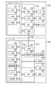
本発明の第1実施形態に係る印刷システム1は、図1に示すように、ホストコンピュータ(外部装置)100(以下、PC100とする)と、PC100にネットワーク300を介して接続可能なプリンタ(情報処理装置)200と、を備えている。この印刷システム1では、PC100とプリンタ200とが双方向インターフェース150(図2参照)を介して通信する。双方向インターフェース150は、LANやUSBなどの有線であっても、無線LANなどの無線であってもよい。この印刷システム1のプリンタ200は、上記したオートシャットダウン機能、オートスリープ機能およびウィークリーシャットダウン機能を有している。
<First Embodiment>
[Overall configuration of printing system]
As shown in FIG. 1, a
[ホストコンピュータのハードウェア構成]
図2に示すように、PC100は、コントローラ120と、キーボード109と、ディスプレイモニタ(CRT)110と、外部メモリ111と、を備えている。
[Hardware configuration of host computer]
As shown in FIG. 2, the PC 100 includes a
コントローラ120は、CPU(Central Processing Unit)101、RAM(Random Access Memory)102、ROM(Read Only Memory)103、キーボードコントローラ(以下、KBCとする)105、CRTコントローラ(以下、CRTCとする)106、メモリコントローラ(以下、MCとする)107、およびインターフェース部(I/F部)108を有している。そして、これらの各デバイスは、システムバス104に接続されている。
The
CPU101は、システムバス104に接続される各デバイスを制御する。そして、CPU101は、ROM103に格納されているプログラムに基づいて様々なデータ処理を行う。例えば、CPU101は、ROM103に格納されている文書処理プログラム等に基づいて、図形、イメージ、文字、表(表計算等を含む)等が混在した文書処理を実行する。さらに、CPU101は、RAM102上に設定された表示情報用RAMに、アウトラインフォントを展開し、CRT110上でのWYSIWYG(What Yot See Is What Yot Get)を実現する。また、CPU101は、ディスプレイモニタ110上のマウスカーソルで指示されたコマンドに基づいて、各種のウィンドウを開き、各種のデータ処理を実行する。
The
RAM102は、CPU101の主メモリおよびワークエリア等として機能する。
The
ROM103は、フォントROM、プログラムROM、データROMから構成される。フォントROMは、文書処理で使用されるフォントデータを記憶する。プログラムROMは、PC100を制御する制御プログラムのほか、プリンタセレクタやネットワークプリンタドライバなどのプログラムを記憶する。データROMは、文書処理などで使用される各種データを記憶する。デ−タ用ROMは、文書処理等で使用される各種デ−タを記憶する。
The
KBC105は、キーボード109やポインティングデバイス(図示せず)からの入力を制御する。
The
CRTC106は、ディスプレイモニタ110の表示を制御する。
The CRTC 106 controls display on the
MC107は、ブートプログラム、種々のアプリケーション、フォントデータ、ユーザファイル、編集ファイル等を記憶するハードディスクドライブ(HDD)等の外部メモリ111との入出力を制御する。
The MC 107 controls input / output to / from an
I/F部108は、双方向インターフェース150を介して行われるプリンタ200との通信を制御する。
The I /
[プリンタのハードウェア構成]
図2に示すように、プリンタ200は、プリンタコントローラ210と、印刷機構部220と、操作部230と、HDD207と、電源スイッチ211と、を備えている。このプリンタ200は、通常電力状態、省電力状態および電源オフ状態を含む複数の電力状態となる。詳細は、後述する。また、電源オフ状態では、上記したプリンタコントローラ210、印刷機構部220、操作部230およびHDD207への電力の供給が停止される。この電源オフ状態への移行は、ユーザが電源スイッチ211をオフにすること、上記したオートシャットダウン機能が実行されること、又は、上記したウィークリーシャットダウン機能が実行されること、により実現される。
[Hardware configuration of printer]
As shown in FIG. 2, the
そして、プリンタコントローラ210は、CPU201、RAM202、ROM203、I/F部301、印刷部インターフェース(以下、印刷部I/F部とする)205、MC部206、電源制御部208、タイマ209およびNVMEM219を有している。そして、これらの各デバイスは、システムバス204に接続されている。タイマ209は、図示しない電池を電力源として動作する。
The
CPU201は、システムバス204に接続される各デバイスを制御する。そして、CPU201は、ROM203に格納されている制御プログラムを実行して、データ処理を実行する。例えば、CPU201は、画像データを生成し、印刷部I/F部205を介して、印刷機構部220に当該画像データに係る画像信号を出力する。また、CPU201は、印刷部I/F部205を介して印刷機構部220に制御信号を送信する。さらに、CPU201は、I/F部301を介してプリンタ200に関する情報をPC100に送信する。
The
RAM202は、CPU201の主メモリおよびワークエリア等として機能する。不図示の増設ポートにオプションRAMを追加することにより、RAM202のメモリ容量は拡張可能である。また、RAM202は、展開された画像データを記憶する画像データ記憶領域、環境データを記憶する環境データ記憶領域、各種パラメータを記憶するNVRAMなどとしても機能する。
The
ROM203はフォントROM、プログラムROM、データROMから構成される。フォントROMは、画像データを生成するために使用されるフォントデータを記憶する。プログラムROMは、CPU201によって実行される制御プログラムを記憶する。データROMは、データ処理などで使用される各種データを記憶する。
The
I/F部301は、双方向インターフェース150を介して行われるPC100との通信を制御する。
The I /
印刷部I/F部205は、印刷機構部220との間の通信を制御する。
The printing unit I /
印刷機構部220は、用紙に画像を形成するために設けられている。
The
操作部230は、キー入力や情報の表示をするための操作パネルであり、スイッチやLED表示器などで構成される。また、操作部230は、タッチパネルであっても良い。
The
MC部206は、HDD207へのアクセスを制御する。HDD207は、印刷データや制御プログラムなどを記憶する。
The
電源制御部208は、CPU201からの信号を受けて、プリンタ200の各部への電力の供給および停止を制御する。この電源制御部208は、通常電力状態において、プリンタコントローラ210、印刷機構部220、操作部230およびHDD207に電力を供給する。また、電源制御部208は、電源オフ状態において、プリンタコントローラ210、印刷機構部220、操作部230、およびHDD207への電力の供給を停止する。電源オフ状態では、プリンタコントローラ210のI/F部301への電力の供給が停止されるので、プリンタ200からPC100への情報の通知が不可能になる。
The power
タイマ209は、CPU201から送信される信号を受けて時間を計測し始める。
The
また、電源スイッチ211は、プリンタ200の各部へ電力を供給したり、プリンタ200の各部への電力の供給を停止したりするためにユーザが操作するスイッチである。この電源スイッチ211は、CPU101から送信される制御信号に応じて、オン状態からオフ状態になる。
The
NVMEM219は、不揮発性メモリである。このNVMEM219は、設定情報を記憶している。この設定情報は、ユーザ名、パスワード、PC名、およびIPアドレスを含む。
The
[電源スイッチおよび電源スイッチの周辺の構成]
次に、図3を参照して、本発明の電源スイッチ211および電源スイッチ211の周辺の構成について説明する。
[Power switch and the configuration around the power switch]
Next, the configuration of the
電源部212は、商用電源213から供給される電力を整流および変圧してDC電源(24V、3.3V)を生成する。
The
また、電源部212と商用電源213との間には、電源スイッチ211が設けられている。この電源スイッチ211は、ソレノイド214およびスイッチ215を有している。ソレノイド214が通電されると、通電されたソレノイド214から発生した磁界によって、スイッチ215の接点が開放される。これにより、電源スイッチ211がオン状態からオフ状態に切り替わり、商用電源213から電源部212へ電力が供給されるのを停止する。本実施形態では、オートシャットダウン機能を実行する条件が満たされた場合に、CPU201がトランジスタ216に制御信号を出力することにより、トランジスタ216がオンになる。これにより、ソレノイド214に電力が供給されてスイッチ215がオフになる。その結果、電源部212からプリンタ200の各部への電力の供給が停止する。なお、オン状態の電源スイッチ211をオフ状態に手動操作により切り替えた場合も、スイッチ215がオフになり、電源部212からプリンタ200の各部への電力の供給が停止する。
A
また、オフ状態の電源スイッチ211をオン状態に手動操作により切り替えた場合は、スイッチ215がオンになり、電源部212からプリンタ200の各部へ電力が供給される。
In addition, when the
[プリンタの電力状態について]
本実施形態のプリンタ200は、通常電力状態、省電力状態および電源オフ状態(特定の電力状態、オフ状態)のいずれかの電力状態となる。プリンタ200は、上記した電源スイッチ211がオンされた場合や印刷処理を実行している場合には、通常電力状態となる。そして、通常電力状態のプリンタ200は、以下の2つの条件を満たした場合に、省電力状態から通常電力状態に移行する。
[About printer power status]
The
(条件1)操作部230のキーの操作が一定時間(Tsl)なかった場合
(条件2)PC100などの外部装置からジョブが一定時間(Tsl)投入されなかった場合
また、省電力状態のプリンタ200は、以下の2つの条件を満たした場合に、省電力状態から電源オフ状態に移行する。
(Condition 1) When the key operation of the
(条件3)操作部230のキーの操作が一定時間(Tsh)なかった場合
(条件4)PC100などの外部装置からジョブが一定時間(Tsh)投入されなかった場合
通常電力状態では、プリンタ200の各部へ電力が供給される。
(Condition 3) When the key operation of the
また、省電力状態では、I/F部205、電源制御部208、タイマ209、NVMEN219、電源スイッチ211には電力が供給されるが、CPU201、RAM202、ROM203、印刷機構部220、HDD207等には電力が供給されない。
In the power saving state, power is supplied to the I /
そして、電源オフ状態では、プリンタ200の各部への電力の供給が停止される。なお、電源オフ状態は、プリンタ200の各部の動作が停止される状態であって、厳密な意味で、プリンタ200の消費電力が0wでなくても構わない。
In the power-off state, the supply of power to each unit of the
[遠隔操作画面の説明]
図4は、PC100のCRT110に表示される遠隔操作画面を示す図である。図4(a)は、ログイン画面500であり、PC100からプリンタ200にアクセスしたときに最初に現れる画面である。
[Description of remote operation screen]
FIG. 4 is a diagram showing a remote operation screen displayed on the
ユーザが、ログイン画面500のユーザ名入力部501aとパスワード入力部501bのそれぞれにユーザ名とパスワードを入力し、管理者ログインボタン502aを押下すると、入力されたユーザ名とパスワードがプリンタ200に送信される。プリンタ200では、受信したユーザ名及びパスワードをNVMEM219に記憶された設定情報に含まれるユーザ名及びパスワードと照合することで管理者に適合するか否かが判定される。そして、受信したユーザ名及びパスワードと設定情報に含まれるユーザ名およびパスワードとが適合すると判定されると、管理者としてのプリンタ200にログインすることが許可される。こうして、プリンタ200は、管理者モードに移行する。
When the user inputs the user name and password to the user
一方、管理者以外の一般ユーザとしてプリンタ200にログインしたい場合には、ユーザ名及びパスワードを入力することなく、一般ユーザログインボタン502bを押下すればよい。これによって、一般ユーザとしてプリンタ200にログインすることが許可される。こうして、プリンタ200は、一般ユーザモードに移行する。
On the other hand, in order to log in to the
なお、管理者としてプリンタ200にログインする場合、及び一般ユーザとしてプリンタ200にログインする場合のいずれの場合でも、PC100は、当該PC100のPC名及びIPアドレスをプリンタ200に送信する。プリンタ200は、受信したPC名及びIPアドレスを、PC100からログアウト通知を受信するまでの間、NVMEM219に保持する。
In both cases of logging in to the
前述の通り、遠隔操作画面401はWEBブラウザベースのアプリケーションであるため、遠隔操作画面401は、プリンタ200において作成されたHTMLデータ等を受信して、WEBブラウザ上にプリンタ200の状態を表示する。
As described above, since the
図4(b)は、図4(a)のログイン画面500を介して管理者としてのログインに成功した場合に、PC100のCRT110に表示される管理者モード画面510の例である。管理者モード画面510のログアウトボタン509が押下されると、管理者モード画面510は閉じられる。
FIG. 4B is an example of the administrator mode screen 510 displayed on the
ステータス表示部503には、プリンタ200の現在の状態や給紙情報、トナー情報等が表示される。ジョブリストボタン504が押下されると、ステータス表示部503にプリンタ200の現在のジョブリスト505が表示される。管理者としてログインしたユーザは、ジョブリスト505表示されたジョブを選択することで、プリンタ200に対してジョブのキャンセル等の所定の操作を要求することができる。例えば、ジョブを選択すると、選択したジョブに関するより詳細な情報(ページ数、ジョブ入力時刻、ユーザ名等)が表示された画面に遷移し、遷移後の画面でジョブのキャンセル等を行うことができる。
The
本実施形態では、管理者モード画面510に限って、ジョブ操作禁止設定ボタン506が表示され、管理者としてログインしたユーザはジョブ操作禁止設定ボタン506を押下することができる構成となっている。すなわち、本実施形態では、管理者モードでは、一般ユーザモードでは実行することができない特定の操作(例えば、ジョブのキャンセルなどの操作禁止設定)を行うことができるようになっている。
In the present embodiment, the job operation
[印刷システムで実行される一連の処理について]
次に、図6を参照して、印刷システム1で実行される一連の処理について説明する。
[A series of processes executed in the printing system]
Next, a series of processes executed in the
PC100のCPU101は、ユーザの操作に応じて、プリンタ200にアクセスする。そうすると、PC100のCPU101は、I/F部108を介して受信した設定情報に基づいて、CRT110にログイン画面500を表示させる。なお、この設定情報は、プリンタ200のNVMEM219に記憶されている。そして、ログイン画面500上で、ユーザによりユーザ名とパスワードとが入力されると(S801)、CPU101は、I/F部108に入力されたユーザ名とパスワードとを送信させる(S802)。これにより、当該ユーザ名とパスワードとが、プリンタ200に送信される。
The
ユーザ名とパスワードとを受信したプリンタ200は、ユーザの認証を行う。すなわち、プリンタ200のCPU201は、NVMEM219に記憶されているユーザ名およびパスワードと、受信したユーザ名およびパスワードと、が一致するか判断する(S803)。一致した場合、CPU101は、受信したPC名およびIPアドレス(以下、適宜ユーザ情報とする)をNVMEM219に記憶する(S804)。そして、CPU101は、I/F部301に認証成功が成功したことを送信させる(S805)。これにより、PC100に認証が成功したことが通知される。上記したS805において、CPU101は、I/F部301に管理者モード画面510の画面情報を送信させる。
The
なお、CPU101が、NVMEM219に記憶されているユーザ名およびパスワードと、受信したユーザ名およびパスワードと、が一致しないと判断した場合(すなわち、認証に失敗した場合)、CPU201は、認証が失敗したことをPC100に通知する。
If the
プリンタ200から送信される認証が成功したことを示す通知を受信したPC100のCPU101は、受信した管理者モード画面510の画面情報に基づいて、CRT110に管理者モード画面510を表示させる(S806)。その後、ユーザが当該画面510等上でプリンタ200の設定の変更などを行うと(S807)、CPU101は、当該設定の変更の要求などをI/F部108に送信させる(S808)。これにより、PC100からプリンタ200に当該設定の変更の要求が送信される。
The
プリンタ200がPC100から設定の変更の要求を受信すると、CPU201は、当該要求に応じて動作する(S809)。例えば、上記した設定の変更として、オートシャットダウン機能が実行されるまでの時間(Tsh)が変更されると、CPU201は、この時間(Tsh)の値の変更を実行する。この際、CPU201は、NVMEM219に設定が変更されたことを示すフラグ(以下、設定変更フラグとする)を記憶する。そして、CPU201は、受信した要求にしたがって実行した処理が完了すると、I/F部301に完了通知を送信させる(S810)。これにより、PC100からの上記下要求が完了したことを示す完了通知が、PC100に送信される。そして、CPU201は、上記した要求が完了したことを管理者モード画面510に表示する(S811)。
When the
そして、プリンタ200からログアウトする場合には、ユーザの操作によりログアウトボタンが押下されることによって(S812)、CPU101は、I/F部108にログアウト通知を送信させる。これにより、ログアウト通知がプリンタ200に送信される(S813)。この際、CPU101は、CRT110に初期画面であるログイン画面500を表示させる。
When logging out from the
ログアウト通知を受信したプリンタ200のCPU201は、NVMEM219に記憶されたユーザ情報(PC名およびIPアドレス)を消去する(S814)。つまり、NVMEM219には、ユーザがプリンタ200にログインしている間だけ、PC100のPC名およびIPアドレスが記憶される。
Receiving the logout notification, the
[プリンタの動作説明]
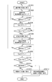
次に、図6を参照して、プリンタ200がオートシャットダウン機能により電源オフ状態になるまでの過程について説明する。プリンタ200のCPU201が、図6のフローチャートに基づくプログラムを実行することにより、この制御方法が実行される。
[Description of printer operation]
Next, a process until the
プリンタ200の電源スイッチ211がオンにされると、CPU201に通電されて、当該CPU201が、印刷機構部220や操作部230などに電力が供給されるようにポートを切り換える。これにより、プリンタ200が通常電力状態に移行する(S901)。そして、CPU201は、ROM203のデータ領域に格納されている通常状態経過時間(Tpnr)の数値を初期化する(「0」にする)(S902)。そして、CPU201は、S903〜S905で、上記した(条件1)および(条件2)を満たすか否かを判断する。具体的には、CPU201は、操作部230のキーの操作があったか否か、およびI/F部301からジョブが投入されたか否かを判断する(S903)。そして、CPU201は、操作部230のキーの操作が無かった場合、およびI/F部301からジョブが投入されない場合(S903:No)、S904の処理を実行する。一方、CPU201は、操作部230のキーの操作があった場合、およびI/F部301からジョブが投入される場合(S903:Yes)、S902の処理を実行する。
When the
CPU201が、操作部230のキーの操作が無かったと判断した場合、およびI/F部301からジョブが投入されていないと判断した場合(S903:No)、CPU201は、ROM203のデータ領域に格納される通常状態経過時間(Tpnr)の数値を更新する(S904)。次に、CPU201は、ROM203のデータ領域に予め格納されている省電力状態移行時間(Tsl)の数値と通常状態経過時間(Tpnr)の数値とを比較する(S905)。
When the
CPU201が通常状態経過時間(Tpnr)がオートスリープ時間(Tsl)より大きくない(Tpnr≦Tsl)と判定した場合(S905:No)、CPU201は、S903の処理を実行する。
When the
一方、通常状態経過時間(Tpnr)がオートスリープ時間(Tsl)より大きい(Tpnr>Tsl)と判定した場合(S905:Yes)、CPU201は、印刷機構部220や操作部230などに電力が供給されないようにポートを切り換える。これにより、プリンタ200が省電力状態に移行する(S906)。そして、CPU201は、ROM203のデータ領域に格納されている省電力状態経過時間(Tpsl)の数値を初期化する(「0」にする)(S907)。
On the other hand, when it is determined that the normal state elapsed time (Tpnr) is greater than the auto sleep time (Tsl) (Tpnr> Tsl) (S905: Yes), the
そして、CPU201は、S908〜S910で、上記した(条件3)および(条件4)を満たすか否かを判断する。具体的には、CPU201は、操作部230のキーの操作があったか否か、およびI/F部301からジョブが投入されたか否かを判断する(S908)。そして、操作部230のキーの操作が無かった場合、およびI/F部301からジョブが投入されない場合(S908:No)、S909の処理を実行する。一方、CPU201は、操作部230のキーの操作があった場合、およびI/F部301からジョブが投入される場合(S908:Yes)、S902の処理を実行する。
Then, the
CPU201が、操作部230のキーの操作が無かったと判断した場合、およびI/F部301からジョブが投入されていないと判断した場合(S908:No)、CPU201は、ROM203のデータ領域に格納される通常状態経過時間(Tpsl)の数値を更新する(S909)。次に、CPU201は、ROM203のデータ領域に予め格納されているオートシャットダウン時間(Tsh)の数値と省電力状態経過時間(Tpsl)の数値とを比較する(S910)。
When the
CPU201が、省電力状態経過時間(Tpsl)がオートシャットダウン時間(Tsh)より大きくない(Tpsl≦Tsh)と判定した場合(移行条件が満たされた場合)(S910:No)、CPU201は、S908の処理を実行する。
When the
一方、省電力状態経過時間(Tpsl)がオートシャットダウン時間(Tsh)より大きい(Tpsl>Tsh)と判定した場合(S910:Yes)、CPU201は、PC100のCRT110に遠隔操作画面(管理者モード画面510)が表示されているか否かを判断する(S911)。具体的には、CPU201は、NVMEM219に記憶される管理者モード画面510の画面情報を送信したか否かを判断する。そして、CPU201が、CRT110に遠隔操作画面が表示されていると判断した場合(S911:Yes)、CPU201は、所定時間経過後に、電源スイッチ211をオフ状態にする(S912)。すなわち、CPU201は、直ちに電源スイッチ211をオフ状態にしない。これにより、プリンタ200の電力状態が、電源オフ状態に移行する。
On the other hand, when determining that the power saving state elapsed time (Tpsl) is larger than the auto shutdown time (Tsh) (Tpsl> Tsh) (S910: Yes), the
一方、CPU201がCRT110に遠隔操作画面が表示されていないと判断した場合(S911:No)、CPU201は、直ちに電源スイッチ211をオフ状態にする(移行処理を実行する)(S913)。なお、CPU201がCRT110に遠隔操作画面が表示されていないと判断する場合とは、CPU201がNVMEM219に記憶される管理者モード画面510の画面情報を送信していない場合である。これにより、プリンタ200の電力状態が、電源オフ状態に移行する。
On the other hand, when the
<第2実施形態>
上記した第1実施形態では、遠隔操作画面がCRT110に表示されている場合には、オートシャットダウン機能を所定時間経過後に実行する例について説明したが、本発明はこれに限らない。第2実施形態では、遠隔操作画面を介してプリンタ200の設定を変更した場合に、オートシャットダウン機能を所定時間経過後に実行する例について説明する。なお、第2実施形態のプリンタの構成は、第1実施形態と同様であるので、その説明は割愛する。
Second Embodiment
In the first embodiment described above, the example in which the auto shutdown function is executed after a predetermined time has elapsed when the remote operation screen is displayed on the
次に、図7を参照して、第2実施形態に係るプリンタ200がオートシャットダウン機能により電源オフ状態になるまでの過程について説明する。プリンタ200のCPU201が、図7のフローチャートに基づくプログラムを実行することにより、この制御方法が実行される。
Next, a process until the
S1001〜S1010までの処理は、第1実施形態のS901〜S910までの処理と同様であるので、その説明を割愛する。 Since the processing from S1001 to S1010 is the same as the processing from S901 to S910 of the first embodiment, the description thereof is omitted.
省電力状態経過時間(Tpsl)がオートシャットダウン時間(Tsh)より大きい(Tpsl>Tsh)と判定した場合(移行条件が満たされた場合)(S1010:Yes)、CPU201は、遠隔操作画面を介してプリンタ200の設定が変更されているか否かを判断する(S1011)。具体的には、CPU201は、NVMEM219に記憶される設定変更フラグが記憶されているか否かを確認して、当該設定変更フラグが記憶されていれば、遠隔操作画面を介してプリンタ200の設定が変更されていると判断する。そして、CPU201が、遠隔操作画面を介してプリンタ200の設定が変更されていると判断した場合(S1011:Yes)、CPU201は、所定時間経過後に、電源スイッチ211をオフ状態にする(S1012)。これにより、プリンタ200の電力状態が、電源オフ状態に移行する。
When it is determined that the power saving state elapsed time (Tpsl) is larger than the auto shutdown time (Tsh) (Tpsl> Tsh) (when the transition condition is satisfied) (S1010: Yes), the
一方、CPU201が、遠隔操作画面を介してプリンタ200の設定が変更されていないと判断した場合(S1011:No)、CPU201は、直ちに電源スイッチ211をオフ状態にする(移行処理を実行する)(S1013)。これにより、プリンタ200の電力状態が、電源オフ状態に移行する。
On the other hand, when the
<第3実施形態>
上記した第1実施形態では、遠隔操作画面がCRT110に表示されている場合には、オートシャットダウン機能を所定時間経過後に実行する例について説明したが、本発明はこれに限らない。すなわち、第3実施形態では、遠隔操作画面がCRT110に表示されている間は、オートシャットダウン機能を実行しない例について説明する。なお、第3実施形態のプリンタの構成は、第1実施形態と同様であるので、その説明は割愛する。
<Third Embodiment>
In the first embodiment described above, the example in which the auto shutdown function is executed after a predetermined time has elapsed when the remote operation screen is displayed on the
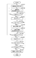
次に、図8を参照して、第3実施形態に係るプリンタ200がオートシャットダウン機能により電源オフ状態になるまでの過程について説明する。プリンタ200のCPU201が、図8のフローチャートに基づくプログラムを実行することにより、この制御方法が実行される。
Next, a process until the
S1101〜S1110までの処理は、第1実施形態のS901〜S910までの処理と同様であるので、その説明を割愛する。 Since the processing from S1101 to S1110 is the same as the processing from S901 to S910 of the first embodiment, the description thereof is omitted.
省電力状態経過時間(Tpsl)がオートシャットダウン時間(Tsh)より大きい(Tpsl>Tsh)と判定した場合(移行条件が満たされた場合)(S1110:Yes)、CPU201は、CRT110に遠隔操作画面(管理者モード画面510)が表示されているか否かを判断する(S1111)。具体的には、CPU201は、NVMEM219に記憶される管理者モード画面510の画面情報を送信したか否かを判断する。そして、CPU201がCRT110に遠隔操作画面が表示されていると判断した場合(S1111:Yes)、CPU201は、操作部230およびI/F部301から信号が入力されるか否かを判断する(S1108)。
When it is determined that the power saving state elapsed time (Tpsl) is greater than the auto shutdown time (Tsh) (Tpsl> Tsh) (when the transition condition is satisfied) (S1110: Yes), the
一方、CPU201が、CRT110に遠隔操作画面が表示されていないと判断した場合(S1111:No)、CPU201は、電源スイッチ211をオフ状態にする(移行処理を実行する)(S1113)。これにより、プリンタ200の電力状態が、電源オフ状態に移行する。
On the other hand, when the
なお、今回開示された実施形態は、すべての点で例示であって制限的なものではないと考えられるべきである。本発明の範囲は、上記した実施形態の説明ではなく特許請求の範囲によって示され、さらに特許請求の範囲と均等の意味および範囲内でのすべての変更が含まれる。 The embodiment disclosed this time should be considered as illustrative in all points and not restrictive. The scope of the present invention is shown not by the above description of the embodiments but by the scope of claims for patent, and further includes all modifications within the meaning and scope equivalent to the scope of claims for patent.
<変形例>
また、上記した第1実施形態および第2実施形態では、遠隔操作画面が表示されている場合および遠隔操作画面を介してプリンタ200の設定の変更を行った場合に、オートシャットダウン機能が所定時間経過後に実行される例について説明したが、本発明はこれに限らない。つまり、本発明は、遠隔操作画面が表示されている場合および遠隔操作画面を介してプリンタ200の設定の変更を行った場合に、ウィークリーシャットダウン機能が所定時間経過後に実行されるようにしても良い。すなわち、本発明の変形例に係るプリンタは、
外部装置と通信可能なプリンタであって、
前記プリンタの電力状態を特定の電力状態に移行させる移行条件が満たされた場合に、前記プリンタの電力状態を前記特定の電力状態に移行させる移行処理を実行する移行手段と、
時刻を計時するタイマと、
前記タイマが計時する時刻が予め設定された時刻(ウィークリーシャットダウン時刻)になった場合に、前記外部装置の表示部に前記情報処理装置の設定を行うための画面を表示しているなら、前記移行手段が前記所定時間経過前に前記移行処理を実行しないように制御する制御手段と、を備える。
<Modification>
In the first and second embodiments described above, when the remote operation screen is displayed and when the setting of the
A printer capable of communicating with an external device,
Transition means for executing a transition process for shifting the power state of the printer to the specific power state when a transition condition for shifting the power state of the printer to the specific power state is satisfied;
A timer that keeps time,
If the screen for setting the information processing device is displayed on the display unit of the external device when the time counted by the timer reaches a preset time (weekly shutdown time), the transition is performed. Control means for controlling the means not to execute the transition process before the predetermined time has elapsed.
上記した第2実施形態では、遠隔操作画面がPC100のCRT110に表示される遠隔操作画面を介してプリンタ200の設定を変更した場合に、オートシャットダウン機能を所定時間経過後に実行する例について説明したが、本発明はこれに限定されない。すなわち、上記した第2実施形態の変形例に係るプリンタは、プリンタ200の特定の設定の変更(例えば、電源をオフにする時刻の設定の変更など)があった場合のみ、オートシャットダウン機能を所定時間経過後に実行するようにしても良い。つまり、この変形例では、遠隔操作画面を介してプリンタ200の設定の変更があった全ての場合に、オートシャットダウン機能を所定時間経過後に実行せずに、プリンタ200の設定の特定の変更があった場合にのみ、オートシャットダウン機能を所定時間経過後に実行する、又は、オートシャットダウン機能を実行しない。
In the above-described second embodiment, the example in which the auto shutdown function is executed after a predetermined time has elapsed when the setting of the
また、上記第1実施形態では、遠隔操作画面が表示されている場合に、オートシャットダウン機能を所定時間経過後に実行する例について説明したが、本発明はそれに限定されない。すなわち、本発明の変形例に係るプリンタは、遠隔操作画面を介して特定のモードでプリンタ200にログインした場合に、オートシャットダウン機能を所定時間経過後に実行するようにしても良い。この特定のモードは、例えば、上記した管理者モードである。すなわち、この変形例に係るプリンタは、NVMEM219にユーザ名及びパスワードが記憶されている間は、オートシャットダウン機能を所定時間経過後に実行する、又は、オートシャットダウン機能を実行しない。
Moreover, although the said 1st Embodiment demonstrated the example which performs an auto shutdown function after progress for a predetermined time, when the remote operation screen is displayed, this invention is not limited to it. That is, the printer according to the modification of the present invention may execute the auto shutdown function after a predetermined time has elapsed when logging into the
上記した第1実施形態では、遠隔操作画面として管理者モード画面510が表示されている場合に、オートシャットダウン機能を所定時間経過後に実行する例について説明したが、本発明はこれに限定されない。すなわち、遠隔操作画面としてログイン画面500が表示されている場合に、オートシャットダウン機能を所定時間経過後に実行しても良い。
In the first embodiment described above, the example in which the auto shutdown function is executed after the elapse of a predetermined time when the administrator mode screen 510 is displayed as the remote operation screen has been described, but the present invention is not limited to this. That is, when the
100 ホストコンピュータ
110 CRT
200 プリンタ
209 タイマ
201 CPU
220 印刷機構部
300 ネットワーク
301 I/F部
500 ログイン画面
510 管理者モード画面
100
200
220
Claims (11)
前記情報処理装置の電力状態を特定の電力状態に移行させる移行条件が満たされた場合に、前記情報処理装置の電力状態を前記特定の電力状態に移行させる移行処理を実行する移行手段と、
前記移行条件が満たされた場合に、前記外部装置の表示部に前記情報処理装置の設定を行うための画面を表示しているなら、前記移行手段が所定時間経過後に前記移行処理を実行するように制御する制御手段と、を備えることを特徴とする、情報処理装置。 An information processing device capable of communicating with an external device,
Transition means for executing a transition process for shifting the power state of the information processing apparatus to the specific power state when a transition condition for shifting the power state of the information processing apparatus to the specific power state is satisfied;
If the screen for setting the information processing apparatus is displayed on the display unit of the external apparatus when the transition condition is satisfied, the transition unit executes the transition process after a predetermined time has elapsed. And an information processing apparatus.
前記受信手段により受信された前記情報を記憶する記憶手段と、をさらに備えることを特徴とする請求項1に記載の情報処理装置。 Receiving means for receiving information indicating that a screen for setting the information processing device is displayed on the display unit of the external device;
The information processing apparatus according to claim 1, further comprising a storage unit that stores the information received by the reception unit.
前記制御手段は、前記タイマが計時する時刻が予め設定された時刻になった場合に、前記外部装置の表示部に前記情報処理装置の設定を行うための画面を表示しているなら、前記移行手段が前記所定時間経過後に前記移行処理を実行するように制御する、ことを特徴とする請求項1に記載の情報処理装置。 A timer for measuring time is further provided.
If the control unit displays a screen for setting the information processing device on the display unit of the external device when the time counted by the timer reaches a preset time, the transition is performed. The information processing apparatus according to claim 1, wherein the control unit performs control so that the transition process is executed after the predetermined time has elapsed.
前記情報処理装置の電力状態を特定の電力状態に移行させる移行条件が満たされた場合に、前記情報処理装置の電力状態を前記特定の電力状態に移行させる移行処理を実行する移行手段と、
前記移行条件が満たされた場合に、前記外部装置の表示部に前記情報処理装置の設定を行うための画面を表示しているなら、前記移行手段が前記移行処理を実行するのを遅延させる制御手段と、を備えることを特徴とする、情報処理装置。 An information processing device capable of communicating with an external device,
Transition means for executing a transition process for shifting the power state of the information processing apparatus to the specific power state when a transition condition for shifting the power state of the information processing apparatus to the specific power state is satisfied;
Control that delays execution of the migration process by the migration means if the screen for setting the information processing device is displayed on the display unit of the external device when the migration condition is satisfied And an information processing apparatus.
前記情報処理装置の電力状態をオフ状態に移行させる移行条件が満たされた場合に、前記情報処理装置の電力状態をオフ状態に移行させる移行処理を実行する移行手段と、
前記移行条件が満たされた場合に、前記外部装置の表示部に表示される前記情報処理装置の設定を行うための画面を介して前記情報処理装置の設定が変更されているなら、前記移行手段が所定時間経過後に前記移行処理を実行するように制御する制御手段と、を備えることを特徴とする、情報処理装置。 An information processing device capable of communicating with an external device,
Transition means for executing a transition process for shifting the power state of the information processing device to an off state when a transition condition for shifting the power state of the information processing device to an off state is satisfied;
If the setting of the information processing device is changed via a screen for setting the information processing device displayed on the display unit of the external device when the transition condition is satisfied, the transition means Control means for performing control so as to execute the transition process after elapse of a predetermined time.
前記情報処理装置の電力状態を特定の電力状態に移行させる移行条件が満たされた場合に、前記外部装置の表示部に前記情報処理装置の設定を行うための画面を表示しているなら、前記情報処理装置の電力状態を前記特定の電力状態に移行させる移行処理を所定時間経過後に実行する、ことを特徴とする、情報処理装置の制御方法。 An information processing apparatus control method capable of communicating with an external device,
When a transition condition for shifting the power state of the information processing device to a specific power state is satisfied, if a screen for setting the information processing device is displayed on the display unit of the external device, A control method for an information processing apparatus, wherein a transition process for shifting the power state of the information processing apparatus to the specific power state is executed after a predetermined time has elapsed.
Priority Applications (5)
| Application Number | Priority Date | Filing Date | Title |
|---|---|---|---|
| JP2012046873A JP2013183352A (en) | 2012-03-02 | 2012-03-02 | Information processor, control method of the same, program and computer readable recording medium |
| KR1020130020208A KR101692254B1 (en) | 2012-03-02 | 2013-02-26 | Image forming apparatus, method for controlling the same, and computer readable storage medium |
| US13/779,548 US9426326B2 (en) | 2012-03-02 | 2013-02-27 | Image forming apparatus, method for controlling the same, and computer readable storage medium |
| CN201310065835.0A CN103297645B (en) | 2012-03-02 | 2013-03-01 | Image forming apparatus and method for controlling the same |
| EP13157399.0A EP2634639B1 (en) | 2012-03-02 | 2013-03-01 | Image forming apparatus, method for controlling the same, program, and computer readable storage medium |
Applications Claiming Priority (1)
| Application Number | Priority Date | Filing Date | Title |
|---|---|---|---|
| JP2012046873A JP2013183352A (en) | 2012-03-02 | 2012-03-02 | Information processor, control method of the same, program and computer readable recording medium |
Publications (2)
| Publication Number | Publication Date |
|---|---|
| JP2013183352A true JP2013183352A (en) | 2013-09-12 |
| JP2013183352A5 JP2013183352A5 (en) | 2015-04-16 |
Family
ID=47891406
Family Applications (1)
| Application Number | Title | Priority Date | Filing Date |
|---|---|---|---|
| JP2012046873A Pending JP2013183352A (en) | 2012-03-02 | 2012-03-02 | Information processor, control method of the same, program and computer readable recording medium |
Country Status (5)
| Country | Link |
|---|---|
| US (1) | US9426326B2 (en) |
| EP (1) | EP2634639B1 (en) |
| JP (1) | JP2013183352A (en) |
| KR (1) | KR101692254B1 (en) |
| CN (1) | CN103297645B (en) |
Cited By (4)
| Publication number | Priority date | Publication date | Assignee | Title |
|---|---|---|---|---|
| JP2015080883A (en) * | 2013-10-22 | 2015-04-27 | セイコーエプソン株式会社 | Printer and printing system |
| JP2016218693A (en) * | 2015-05-19 | 2016-12-22 | キヤノン株式会社 | Communication device, control method, and program |
| JP2018138332A (en) * | 2017-02-24 | 2018-09-06 | 京セラドキュメントソリューションズ株式会社 | Display device and image forming apparatus |
| JPWO2020241706A1 (en) * | 2019-05-31 | 2020-12-03 |
Families Citing this family (3)
| Publication number | Priority date | Publication date | Assignee | Title |
|---|---|---|---|---|
| JP5968103B2 (en) * | 2012-06-18 | 2016-08-10 | キヤノン株式会社 | Image processing controller and control method thereof |
| JP6020353B2 (en) * | 2013-05-29 | 2016-11-02 | コニカミノルタ株式会社 | Information processing apparatus, image forming apparatus, remote operation method, remote control method, remote operation program, and remote control program |
| JP2018093433A (en) * | 2016-12-06 | 2018-06-14 | キヤノン株式会社 | Communication system, image forming device and control method thereof, and program |
Citations (4)
| Publication number | Priority date | Publication date | Assignee | Title |
|---|---|---|---|---|
| JP2002091630A (en) * | 2000-09-19 | 2002-03-29 | Canon Inc | Information processor and method for controlling the same and storage medium |
| JP2003084931A (en) * | 2001-07-02 | 2003-03-20 | Seiko Epson Corp | Printing method via network |
| JP2006041739A (en) * | 2004-07-23 | 2006-02-09 | Fuji Xerox Co Ltd | Image processing apparatus |
| JP2007288584A (en) * | 2006-04-18 | 2007-11-01 | Murata Mach Ltd | Network composite machine |
Family Cites Families (12)
| Publication number | Priority date | Publication date | Assignee | Title |
|---|---|---|---|---|
| JPH0876653A (en) | 1994-09-05 | 1996-03-22 | Canon Inc | Image forming device |
| US6388758B2 (en) * | 1997-11-17 | 2002-05-14 | Canon Kabushiki Kaisha | System for scheduling an event in a device based on elapsed time or device event |
| JP3946330B2 (en) * | 1997-12-19 | 2007-07-18 | シャープ株式会社 | Data processing system |
| KR100338734B1 (en) * | 1998-07-31 | 2002-07-18 | 윤종용 | Printer and method of controlling power consumption of the same |
| JP2000081959A (en) | 1998-09-07 | 2000-03-21 | Canon Inc | Data processor, printing controller, data processing method for data processor, data processing method for printing controller, and storage medium storing computer readable program |
| US7239409B2 (en) * | 2001-06-22 | 2007-07-03 | Hewlett-Packard Development Company, L.P. | Remote access to print job retention |
| US7260730B2 (en) * | 2002-10-21 | 2007-08-21 | Canon Kabushiki Kaisha | Remote power configuration of functions within multifunction apparatus using status and setting screens displayed on external apparatus |
| JP3938133B2 (en) * | 2002-10-21 | 2007-06-27 | キヤノン株式会社 | Information processing apparatus and power supply control method thereof |
| US20050254082A1 (en) * | 2004-05-10 | 2005-11-17 | Ayako Kobayashi | Image forming device, data erasing method, and recording medium |
| JP4615498B2 (en) * | 2005-09-22 | 2011-01-19 | シャープ株式会社 | Image processing apparatus, image processing apparatus control system, image processing apparatus control method, program, and computer-readable recording medium |
| JP5180613B2 (en) | 2008-02-19 | 2013-04-10 | キヤノン株式会社 | Information processing apparatus and control method thereof |
| JP2012043071A (en) * | 2010-08-16 | 2012-03-01 | Canon Inc | Adjusting system, adjusting device, adjusting method and program for the same |
-
2012
- 2012-03-02 JP JP2012046873A patent/JP2013183352A/en active Pending
-
2013
- 2013-02-26 KR KR1020130020208A patent/KR101692254B1/en active IP Right Grant
- 2013-02-27 US US13/779,548 patent/US9426326B2/en not_active Expired - Fee Related
- 2013-03-01 EP EP13157399.0A patent/EP2634639B1/en active Active
- 2013-03-01 CN CN201310065835.0A patent/CN103297645B/en not_active Expired - Fee Related
Patent Citations (4)
| Publication number | Priority date | Publication date | Assignee | Title |
|---|---|---|---|---|
| JP2002091630A (en) * | 2000-09-19 | 2002-03-29 | Canon Inc | Information processor and method for controlling the same and storage medium |
| JP2003084931A (en) * | 2001-07-02 | 2003-03-20 | Seiko Epson Corp | Printing method via network |
| JP2006041739A (en) * | 2004-07-23 | 2006-02-09 | Fuji Xerox Co Ltd | Image processing apparatus |
| JP2007288584A (en) * | 2006-04-18 | 2007-11-01 | Murata Mach Ltd | Network composite machine |
Cited By (7)
| Publication number | Priority date | Publication date | Assignee | Title |
|---|---|---|---|---|
| JP2015080883A (en) * | 2013-10-22 | 2015-04-27 | セイコーエプソン株式会社 | Printer and printing system |
| JP2016218693A (en) * | 2015-05-19 | 2016-12-22 | キヤノン株式会社 | Communication device, control method, and program |
| US10129425B2 (en) | 2015-05-19 | 2018-11-13 | Canon Kabushiki Kaisha | Communication apparatus capable of shifting to at least one of a first state and a second state in which less power is consumed than in the first state, and a control method and a non-transitory computer-readable storage medium for use with same |
| JP2018138332A (en) * | 2017-02-24 | 2018-09-06 | 京セラドキュメントソリューションズ株式会社 | Display device and image forming apparatus |
| JPWO2020241706A1 (en) * | 2019-05-31 | 2020-12-03 | ||
| WO2020241706A1 (en) * | 2019-05-31 | 2020-12-03 | 京セラドキュメントソリューションズ株式会社 | Image formation device, print system, and method for controlling power supply of image formation device |
| JP7140285B2 (en) | 2019-05-31 | 2022-09-21 | 京セラドキュメントソリューションズ株式会社 | IMAGE FORMING APPARATUS, PRINT SYSTEM, AND POWER CONTROL METHOD FOR IMAGE FORMING APPARATUS |
Also Published As
| Publication number | Publication date |
|---|---|
| CN103297645A (en) | 2013-09-11 |
| CN103297645B (en) | 2017-04-19 |
| EP2634639B1 (en) | 2020-05-13 |
| EP2634639A2 (en) | 2013-09-04 |
| US9426326B2 (en) | 2016-08-23 |
| KR101692254B1 (en) | 2017-01-04 |
| US20130229689A1 (en) | 2013-09-05 |
| EP2634639A3 (en) | 2017-08-23 |
| KR20130100709A (en) | 2013-09-11 |
Similar Documents
| Publication | Publication Date | Title |
|---|---|---|
| JP2013183352A (en) | Information processor, control method of the same, program and computer readable recording medium | |
| JP6004883B2 (en) | Image forming apparatus, control method therefor, and program | |
| JP4867475B2 (en) | Image forming system and image forming apparatus | |
| JP2016055550A (en) | Image forming device, control method for the same and program | |
| JP6711576B2 (en) | Image forming apparatus, image forming apparatus control method, and program. | |
| JP2016058911A (en) | Information processing unit capable of controlling mechanical switch of power supply and control method thereof, and program | |
| JP2000218894A (en) | Imaging system | |
| JP2015101028A (en) | Image formation device, control method for image formation device, recording medium, and program | |
| JP2011025562A (en) | Image forming apparatus, control method thereof and control program thereof | |
| JP2010089424A (en) | Printer | |
| JP5948760B2 (en) | Image forming apparatus and operation method thereof | |
| JP4951353B2 (en) | Image forming apparatus and image forming system | |
| CN108984135B (en) | Image forming apparatus, state control method of the image forming apparatus, and image forming system | |
| JP7161396B2 (en) | Information processing device, its control method, and program | |
| KR102578385B1 (en) | Electronic apparatus enabling omission of software tampering detection processing at activation | |
| JP5873325B2 (en) | Image forming apparatus | |
| JP5048570B2 (en) | Printing system and printer | |
| JP2017007344A (en) | Printer and control method thereof | |
| JP2017105164A (en) | Image formation device, control method of image formation device, and program | |
| JP6039753B2 (en) | Information processing apparatus and control method thereof | |
| JP6291983B2 (en) | Recovery device and recovery method | |
| JP2024032067A (en) | Information processing device and method of controlling the information processing device | |
| JP2009199337A (en) | Print system and print program | |
| JP2013242926A (en) | Information processing device, and method of controlling the same | |
| JP2015125622A (en) | Information processing device |
Legal Events
| Date | Code | Title | Description |
|---|---|---|---|
| A521 | Request for written amendment filed |
Free format text: JAPANESE INTERMEDIATE CODE: A523 Effective date: 20150302 |
|
| A621 | Written request for application examination |
Free format text: JAPANESE INTERMEDIATE CODE: A621 Effective date: 20150302 |
|
| A977 | Report on retrieval |
Free format text: JAPANESE INTERMEDIATE CODE: A971007 Effective date: 20151118 |
|
| A131 | Notification of reasons for refusal |
Free format text: JAPANESE INTERMEDIATE CODE: A131 Effective date: 20151215 |
|
| A521 | Request for written amendment filed |
Free format text: JAPANESE INTERMEDIATE CODE: A523 Effective date: 20160205 |
|
| A131 | Notification of reasons for refusal |
Free format text: JAPANESE INTERMEDIATE CODE: A131 Effective date: 20160607 |
|
| A02 | Decision of refusal |
Free format text: JAPANESE INTERMEDIATE CODE: A02 Effective date: 20161206 |