JP6039753B2 - Information processing apparatus and control method thereof - Google Patents
Information processing apparatus and control method thereof Download PDFInfo
- Publication number
- JP6039753B2 JP6039753B2 JP2015126771A JP2015126771A JP6039753B2 JP 6039753 B2 JP6039753 B2 JP 6039753B2 JP 2015126771 A JP2015126771 A JP 2015126771A JP 2015126771 A JP2015126771 A JP 2015126771A JP 6039753 B2 JP6039753 B2 JP 6039753B2
- Authority
- JP
- Japan
- Prior art keywords
- state
- information processing
- power
- switch
- processing apparatus
- Prior art date
- Legal status (The legal status is an assumption and is not a legal conclusion. Google has not performed a legal analysis and makes no representation as to the accuracy of the status listed.)
- Active
Links
Images


Landscapes
- Accessory Devices And Overall Control Thereof (AREA)
- Power Sources (AREA)
Description
本発明は、情報処理装置及びその制御方法に関する。 The present invention relates to an information processing apparatus and a control method thereof .
情報処理装置には、装置の電源スイッチがオフにされると、装置のシャットダウンを実行し、装置への電力供給を停止するものがある。 Some information processing apparatuses shut down the apparatus and stop supplying power to the apparatus when the power switch of the apparatus is turned off.
特許文献1には、電源スイッチがオフにされたらシャットダウンを開始し、シャットダウン処理が完了した時点で、電源スイッチの状態を確認する発明が記載されている。特許文献1に記載された発明では、前記確認の結果、電源スイッチがオフになっていれば、装置への電力供給を停止し、電源スイッチがオンになっていれば、装置の再起動を実行する。 Patent Document 1 describes an invention in which a shutdown is started when a power switch is turned off and the state of the power switch is confirmed when the shutdown process is completed. In the invention described in Patent Document 1, if the power switch is turned off as a result of the confirmation, the power supply to the device is stopped, and if the power switch is turned on, the device is restarted. To do.
一方、ネットワーク等で接続された外部装置からの命令によって、情報処理装置の電源をオフにする技術が存在する。 On the other hand, there is a technique for turning off the power of the information processing apparatus according to a command from an external apparatus connected via a network or the like.
しかし、特許文献1の発明に対して上記の技術を適用させた場合、以下のような問題が発生してしまう。すなわち、外部装置からの命令によって情報処理装置の電源をオフにすると、スイッチはオン状態のままである。 However, when the above technique is applied to the invention of Patent Document 1, the following problems occur. That is, when the information processing apparatus is turned off by a command from the external apparatus, the switch remains in the on state.
本発明は、外部装置から情報処理装置の電源をオフにするための指示を受けることが可能な情報処理装置において、スイッチをオフ状態にすることが可能な情報処理装置及びその制御方法を提供することを目的とする。 The present invention provides an information processing apparatus capable of turning off a switch in an information processing apparatus capable of receiving an instruction to turn off the power of the information processing apparatus from an external device, and a control method thereof. For the purpose.
上記の目的を達成するため、本発明の情報処理装置は、外部装置と通信可能な情報処理装置であって、ユーザの操作に応じてオン状態又はオフ状態になるスイッチと、前記スイッチをオン状態からオフ状態にする駆動手段と、前記スイッチと並列に配置されるリレーと、前記外部装置から前記情報処理装置の電源をオフにするための指示を受信したことに基づいて、前記情報処理装置のシャットダウン処理を実行する実行手段と、前記実行手段が前記シャットダウン処理の実行を開始した後に、前記駆動手段を制御して前記スイッチをオン状態からオフ状態にすると共に、前記リレーをオン状態からオフ状態にする電源制御手段と、を備えることを特徴とする。 In order to achieve the above object, an information processing apparatus according to the present invention is an information processing apparatus capable of communicating with an external device, a switch that is turned on or turned off according to a user operation, and the switch that is turned on. The information processing device based on receiving an instruction to turn off the power of the information processing device from the external device, a driving unit for turning off the information processing device, a relay arranged in parallel with the switch, An execution means for executing a shutdown process; and after the execution means starts executing the shutdown process , the drive means is controlled to change the switch from an on state to an off state, and the relay is changed from an on state to an off state. Power supply control means.
本発明によれば、外部装置から情報処理装置の電源をオフにするための指示を受けることが可能な情報処理装置において、スイッチをオフ状態にすることが可能となる。 ADVANTAGE OF THE INVENTION According to this invention, in the information processing apparatus which can receive the instruction | indication for turning off the power supply of an information processing apparatus from an external device, it becomes possible to make a switch into an OFF state.
以下、本発明の実施の形態について、図面を参照して説明する。 Embodiments of the present invention will be described below with reference to the drawings.
なお、以下の説明において、情報処理装置の一例としてプリンタを、外部装置の一例としてPCを挙げて説明するが、情報処理装置及び外部装置はこれらの例に限定されるものではない。 In the following description, a printer will be described as an example of the information processing apparatus, and a PC will be described as an example of the external apparatus. However, the information processing apparatus and the external apparatus are not limited to these examples.
また、以下の説明において、電源オフ処理とは、装置の電源をオフにするための処理のことであり、装置のシャットダウン及び装置への電力供給の停止を含むものとする。 In the following description, the power-off process is a process for turning off the power of the apparatus, and includes shutting down the apparatus and stopping power supply to the apparatus.
また、以下の説明において、シャットダウンとは、ファイルのクローズ、アプリケーションプログラムの終了、各種入出力装置との通信の切断、OSの終了等の処理を実行すること意味する。 Further, in the following description, shutdown means execution of processing such as file closing, application program termination, communication disconnection with various input / output devices, OS termination, and the like.
また、以下の説明において、再起動とは、シャットダウンが完了した後に、BIOS、OSの起動等の処理を実行することを意味する。 Further, in the following description, “restart” means that after shutdown is completed, processing such as BIOS and OS startup is executed.
〔第1の実施の形態〕
図1は、本実施の形態に係るプリンタの構成を示すブロック図である。
[First Embodiment]
FIG. 1 is a block diagram illustrating a configuration of a printer according to the present embodiment.
プリンタ1は、外部I/Fにより、PC2とネットワークを介して通信可能に接続される。プリンタ1は、PC2からプリンタ1の電源をオフにするための命令を受信することが可能である。 The printer 1 is communicably connected to the PC 2 via a network by an external I / F. The printer 1 can receive a command for turning off the power of the printer 1 from the PC 2.
プリンタ1は、電源スイッチ部10、電源リレー部11、AC/DC電源部12、コントローラ部13、及びプリント部19を有している。
The printer 1 includes a
電源スイッチ部10は、交流(AC)電源からの電力供給のオン/オフを指示するための電源スイッチを有している。この電源スイッチは、ソレノイドスイッチである。ソレノイドスイッチは、スイッチとアクチュエータによって構成され、手動又は自動でスイッチをオンオフすることが可能である。アクチュエータ(駆動手段)は、ソレノイドと鉄芯(ソレノイドの中に配置される)により構成され、ソレノイドに電流を流すことにより、鉄芯を動作させ、スイッチを自動でオンオフさせることが可能となっている。また、電源スイッチ部10は、電源スイッチのオン/オフ状態を電源制御部14に通知する機能を有している。
The
電源リレー部11は、電源制御部14からの信号に基づいて、電源スイッチがオフ状態であっても、外部からの交流電源をAC/DC電源部12に供給するために設けられている。
The power
AC/DC電源部12は、装置外部から供給される交流電源を直流電源に変換して、コントローラ部13やプリント部19等の各デバイスに供給する。
The AC / DC
コントローラ部13は、電源制御部14、リセット部15、HDD16、CPU17、及びメモリ18を有している。
The
電源制御部14は、電源スイッチのオン/オフ状態を検出して、電源オフ処理、リセット処理、電源オフ処理等の処理を指示する信号を出力する。
The
リセット部15は、当該コンピュータシステムを再起動する場合等、電源制御部14からのリセット指示信号に基づいて、コントローラ部13のハードウェア全体に対してリセット処理を行う。
The
HDD16は、当該コンピュータシステムで実行する各種のソフトウェアやデータを格納する。なお、HDD16には、OS、装置に特有の情報処理等を行う各種のアプリケーションプログラム(制御プログラム)が格納され、この各種の制御プログラムの中には、電源オフ処理に係る制御プログラムも含まれている。
The HDD 16 stores various software and data executed by the computer system. Note that the
CPU17は、電源制御部14からの指示信号に基づいて電源オフ処理、リセット処理等を実行すると共に、プリンタ1に係るシステム全体の制御を行う。
The
メモリ18は、DDR SDRAM等の揮発性メモリにより構成されており、CPU17のワークエリア等として利用される。
The
プリント部19は、CPUの制御に基づいて、プリント処理を実行する。 The print unit 19 executes print processing based on the control of the CPU.
操作部20は、表示画面と入力ボタンを有し、操作者からの各種操作を受け付ける。
The
図2は、本実施の形態に係る電源制御部14の構成を示すブロック図である。
FIG. 2 is a block diagram illustrating a configuration of the power
電源制御部14は、シャットダウン制御部140、割り込み制御部141、及びリレー制御部142を有している。
The power
シャットダウン制御部140は、電源スイッチ部10からのスイッチ状態信号と、リレー制御部142からのリレー断指示信号を受け取る。そして、シャットダウン制御部140は、スイッチ状態信号とリレー断指示信号に基づいて遠隔操作による電源断指示操作であると判断した場合は、電源断処理を実行させための電源スイッチ制御信号を電源スイッチ部10に出力する。また、シャットダウン制御部140は、スイッチ状態信号がオン状態からオフ状態に変化した後に再度オン状態になった場合は、リセット指示信号をリセット部15に出力してハードウェアをリセットさせる。これにより、CPU17は、ハードウェアがリセットされた状態でコンピュータシステムを再起動することが可能となる。
The
割り込み制御部141は、電源スイッチ部10から電源スイッチのスイッチ状態信号を受け取ることにより、電源スイッチのオン/オフ状態を監視する。そして、割り込み制御部141は、電源スイッチがオン状態からオフ状態に変化した場合に、CPU17に対する割り込み信号をアサートすることで、電源スイッチがオフされたことをCPU17に通知する。
The
リレー制御部142は、CPU17からの指示信号に基づいて、電源リレー断(オフ)指示信号を電源リレー部11に出力する。
The
図3は、本実施の形態に係るシャットダウン制御部140の内部構成を示すブロック図である。
FIG. 3 is a block diagram showing an internal configuration of
シャットダウン制御部140は、AND回路1400,1403,1405、NOT回路1401,1404、及びフリップフロップ(FF)回路1402を有している。
The
AND回路1400は、リレー断指示信号とスイッチ状態信号の論理積値を、信号2としてAND回路1403,1405に出力する。
The
NOT回路1401は、スイッチ状態信号を反転させてフリップフロップ回路1402に入力する。
The
フリップフロップ回路1402は、スイッチ状態信号のオン/オフの変化状態を保持し、その変化状態を信号1としてAND回路1403,1405に出力する。ただし、信号1は、AND回路1405に対してはNOT回路1404を介して出力される。
The flip-
AND回路1403は、出力信号を、リセット指示信号としてリセット部15へ出力させる。また、AND回路1405は、出力信号を、電源スイッチ制御信号として電源スイッチ部10へ出力させる。
The AND
図1〜図3に示した構成の下で、電源制御部14により電源オフ処理を行う場合、その制御信号は、次に示す図4、図5、図6のタイミングチャートのようになる。
When the
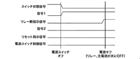
図4は、本発明の実施の形態に係る電源オフ処理において電源スイッチがオフにされ再度オンされなかった場合の制御信号の状態を示すタイミングチャートである。 FIG. 4 is a timing chart showing the state of the control signal when the power switch is turned off and not turned on again in the power-off process according to the embodiment of the present invention.
ここで、通常動作時は、ユーザの意に反して電源スイッチが切断された場合でもAC/DC電源部12にAC電源を供給することができるように、リレー制御部142は、リレー断信号をLレベルにして、電源リレー部11をオン状態に設定している。
Here, during normal operation, the
割り込み制御部141は、電源スイッチ部10から出力されるスイッチ状態信号のオン/オフ変化状況を監視している。
The interrupt
そして、スイッチ状態信号がオン(Hレベル)からオフ(Lレベル)に変化した場合は、割り込み制御部141は、CPU17に対して割り込み信号をアサートすることで、CPU17に電源スイッチがオフされたことを通知する。
When the switch state signal changes from on (H level) to off (L level), the interrupt
なお、スイッチ状態信号がオンからオフに変化した場合は、図4に示すようにフリップフロップ回路1402の出力信号である信号1はHレベルに変化する。
When the switch state signal changes from on to off, the signal 1 that is the output signal of the flip-
CPU17は、割り込み信号がアサートされると、シャットダウン用のソフトウェアを実行する。
When the interrupt signal is asserted, the
CPU17は、HDD16等に対するシャットダウンが完了すると、リレー制御部142に対して、シャットダウンの完了を通知する。
When the shutdown of the
リレー制御部142は、シャットダウンの完了通知を受けると、図4に示すように、リレー断信号をHレベルに変化させて、電源リレー部11をオフ状態に設定する。
When the
なお、図4に示すように、電源スイッチのスイッチ状態信号がオンからオフに変化しただけの場合は、次のようになる。AND回路1400の出力信号である信号2、AND回路1403の出力信号であるリセット指示信号、及びAND回路1405の出力信号である電源スイッチ制御信号は、Lレベルのままであり、変化することはない。
As shown in FIG. 4, when the switch state signal of the power switch is merely changed from on to off, the following occurs. The
このような制御信号の一連の変化によってシャットダウンが開始され、そのシャットダウンが完了した後は、電源スイッチ部10の電源スイッチ及び電源リレー部11が共にオフ状態となって、電源断(電源オフ)が完了する。
Shutdown is started by a series of changes in the control signal, and after the shutdown is completed, both the power switch of the
図5は、本実施の形態に係る電源オフ処理において電源スイッチがオフにされた後に再度オンされた場合の制御信号の状態を示すタイミングチャートである。 FIG. 5 is a timing chart showing the state of the control signal when the power switch is turned on again after being turned off in the power-off process according to the present embodiment.
前述のように、電源スイッチがオンからオフに変化すると、CPU17は、ソフトウェアによるシャットダウンを開始する。
As described above, when the power switch changes from on to off, the
電源スイッチがオンからオフに変化した場合は、図5に示すように、フリップフロップ回路1402の出力信号である信号1はHレベルに変化する。
When the power switch changes from on to off, as shown in FIG. 5, the signal 1 that is the output signal of the flip-
シャットダウン処理が完了する前、又はシャットダウン処理が完了しリレー制御部142が電源リレー部11をオフに設定する前の段階では、次のようになる。電源スイッチがオフからオンに変化した場合、即ちユーザが再起動を指示した場合は、リレー断指示信号とスイッチ状態信号が共にHレベルとなる。
At a stage before the shutdown process is completed or before the shutdown process is completed and the
これにより、AND回路1400の出力信号である信号2がLレベルからHレベルに変化する。
As a result, the
さらに、信号1、信号2が共にHレベルとなることで、AND回路1403の出力信号であるリセット指示信号がLレベルからHレベルに変化する。
Furthermore, when both signal 1 and
リセット指示信号がHレベルに変化することで、リセット部15は、必要な時間だけハードウェア・リセットラインをアサートし、CPU17及びその周辺のハードウェアをリセットする。
When the reset instruction signal changes to the H level, the
そして、CPU17は、再起動用の所定のソフトウェアに基づいて、システムの再起動処理を行う。
Then, the
図6は、本実施の形態に係る電源オフ処理において遠隔操作により電源オフが指示された場合の制御信号の状態を示すタイミングチャートである。 FIG. 6 is a timing chart showing the state of the control signal when power-off is instructed by remote operation in the power-off processing according to the present embodiment.
PC2からの遠隔操作による電源断の操作信号は、CPU17に接続されたネットワークI/F(図示省略)から直接CPU17に入力される。
A power-off operation signal by remote operation from the
CPU17は、この遠隔操作による電源断の操作信号が入力されると、シャットダウン用のソフトウェアを実行する。
When the power-off operation signal is input by the remote operation, the
この場合、図6に示すように、電源スイッチはオン状態のまま変化せずスイッチ状態信号はHレベルを維持するため、フリップフロップ回路1402の出力信号である信号1としては、Lレベルが出力される。
In this case, as shown in FIG. 6, since the power switch remains in the ON state and the switch state signal maintains the H level, the L level is output as the signal 1 that is the output signal of the flip-
シャットダウンが終了し、リレー制御部142が電源リレー部11をオフに設定する段階では、電源スイッチがオンの状態になっているため、図6に示すように、リレー断指示信号とスイッチ状態信号が共にHレベルとなっている。
When the shutdown is completed and the
これにより、AND回路1400の出力信号である信号2がHレベルに変化する。
As a result, the
さらに、NOT回路1404により信号1が論理反転されてHレベルとなり、信号2もHレベルとなることで、図6に示すように、AND回路1405の出力信号である電源スイッチ制御信号がHレベルに変化する。
Further, the signal 1 is logically inverted by the
電源スイッチ部10は、電源スイッチ制御信号がHレベルに変化すると、ソレノイドスイッチで構成された電源スイッチをオフに設定する。
When the power switch control signal changes to the H level, the
このような一連の処理によって、電源スイッチ部10及び電源リレー部11が共にオフ状態となり、プリンタ1の電源断が完了する。
Through such a series of processes, both the
なお、上記のリセット指示信号、及び電源スイッチ制御信号の出力処理は、上記のような論理回路を用いることなく、図7のフローチャートに示す制御を実行するソフトウェアにより行うことも可能である。 Note that the output processing of the reset instruction signal and the power switch control signal can be performed by software that executes the control shown in the flowchart of FIG. 7 without using the logic circuit as described above.
図7は、本実施の形態に係る電源オフ処理の動作を示すフローチャートである。 FIG. 7 is a flowchart showing the operation of the power-off process according to the present embodiment.
まず、CPU17は、電源スイッチのオンからオフへの変化で割り込み制御部141から割り込み信号を受信する、又はPC2から遠隔操作による電源断信号を受信することにより、電源オフの指示を入力する(S701)。
First, the
次に、CPU17は、その旨の情報(S701における電源オフの指示が、プリンタの電源スイッチによるものであったか、PCからの電源オフの命令によるものであったかを示す情報)をメモリ18に記憶する(S702)。
Next, the
次に、CPU17は、ソフトウェアによりプリンタ1のシャットダウンを実行する(S703)。S703のシャットダウンが終了したら、S704に移行する。
Next, the
次に、CPU17は、電源スイッチ部10の電源スイッチの状態を確認して、電源スイッチが、オンの状態になっているか、オフの状態になっているかを判断する(第1の判断)(S704)。なお、S704で、電源スイッチがオンの状態になっていると判断される場合としては、電源スイッチが直接オフにされた後に直接オンにされた場合や、外部装置からの命令により電源オフが指示された場合等が該当する。また、S704で、電源スイッチがオフの状態になっていると判断される場合としては、電源スイッチが直接オフにされた後に直接オンにされることがなかった場合等が該当する。S704で、電源スイッチがオンの状態になっていると判断された場合、S705に移行する。S704で、電源スイッチがオフの状態になっていると判断された場合、S710に移行する。
Next, the
S704で、電源スイッチがオンの状態になっていると判断された場合、CPU17は、以下の処理を実行する。
If it is determined in S704 that the power switch is turned on, the
まず、CPU17は、S702で記憶された情報に基づいて、S701における電源オフの指示が、プリンタの電源スイッチによるものであったか、PCからの電源オフの命令によるものであったかを判断する(第2の判断)(S705)。S705で、S701における電源オフの指示がPCからの電源オフの命令によるものであったと判断された場合、S706に移行する。S705で、S701における電源オフの指示がプリンタの電源スイッチによるものであったと判断された場合、S708に移行する。
First, based on the information stored in S702, the
S705で、S701における電源オフの指示がPCからの電源オフの命令によるものであったと判断された場合、CPU17は、以下の処理を実行する。
If it is determined in S705 that the power-off instruction in S701 is based on a power-off instruction from the PC, the
まず、CPU17は、リレー制御部142を介して電源リレー部11をオフに設定する(S706)。
First, the
次に、CPU17は、操作部20の表示画面に、電源スイッチのオフを促すためのメッセージを表示し、プリンタ1の操作者により電源スイッチ部10の電源スイッチがオフされるのを待つ(S707)。メッセージとしては、例えば「シャットダウンが完了しました。電源スイッチをオフにして下さい。」という内容を表示すればよい。こうすることにより、操作者は、電源スイッチをオフにした後で、シャットダウン処理が終了するまでプリンタの前で待たずに済むようになる。
Next, the
なお、S707では、メッセージを表示して操作者により電源スイッチがオフされるのを待つ代わりに、電源スイッチ部10の電源スイッチを自動でオフにしても構わない。この場合、例えば、電源スイッチのアクチュエータに電圧を印加することにより、電源スイッチを強制的にオフにすればよい。こうすることにより、操作者は、プリンタの電源をオフにするために、プリンタの場所まで行かずに済むようになる。
In step S707, the power switch of the
以上により、リレー及び電源スイッチがオフの状態になるので、プリンタ1への電力供給は停止される。 As a result, the relay and the power switch are turned off, so that the power supply to the printer 1 is stopped.
S705で、S701における電源オフの指示がプリンタの電源スイッチによるものであったと判断された場合、CPU17は、以下の処理を実行する。
If it is determined in step S705 that the power-off instruction in step S701 is from the printer power switch, the
まず、CPU17は、リレー制御部142を介して電源リレー部11をオフに設定する(S708)。なお、この時点でスイッチがオンの状態であるため、リレーがオフの状態になっても、プリンタ1への電力供給は継続される。また、S709でシステムの再起動にリレーをオンにする処理が含まれないのであれば、S708を省略する(リレーをオンにしたままにする)ことにしても構わない。
First, the
次に、CPU17は、システムの再起動を実行する(S709)。なお、システムの再起動には、S708でリレーをオンにする場合、リレーをオンにする処理が含まれるものとする。
Next, the
以上により、装置が再起動され、プリンタ1への電力供給は継続される。 As described above, the apparatus is restarted and the power supply to the printer 1 is continued.
S704で、電源スイッチが、オフの状態になっていると判断された場合、CPU17は、以下の処理を実行する。
If it is determined in step S704 that the power switch is turned off, the
まず、CPU17は、リレー制御部142を介して電源リレー部11をオフに設定する(S710)。
First, the
以上により、リレー及び電源スイッチがオフの状態になるので、プリンタ1への電力供給は停止される。 As a result, the relay and the power switch are turned off, so that the power supply to the printer 1 is stopped.
本実施の形態によれば、電源スイッチ及びPCからの命令により電源をオフにすることが可能なプリンタにおいて、プリンタの電源を適切にオフにすることが可能となる。 According to this embodiment, in a printer that can be turned off by a command from the power switch and the PC, the printer can be appropriately turned off.
〔他の実施の形態〕
また、本発明の目的は、以下の処理を実行することによっても達成される。
[Other Embodiments]
The object of the present invention can also be achieved by executing the following processing.
すなわち、上記の実施の形態の機能を実現するソフトウェアのプログラムコードを記憶した記憶媒体を、システム或いは装置に供給し、そのシステム或いは装置のコンピュータが記憶媒体に記憶されたプログラムコードを読み出す処理である。 That is, a process of supplying a storage medium storing software program codes for realizing the functions of the above-described embodiments to a system or apparatus, and a computer of the system or apparatus reading out the program codes stored in the storage medium. .
この場合、記憶媒体から読み出されるプログラムコード自体が前述の実施の形態の機能を実現することになり、そのプログラムコード及び該プログラムコードを記憶した記憶媒体は本発明を構成することになる。 In this case, the program code itself read from the storage medium realizes the functions of the above-described embodiment, and the program code and the storage medium storing the program code constitute the present invention.
10 電源スイッチ部10
14 電源制御部14
17 CPU17
20 操作部20
10
14 Power
17
20
Claims (41)
ユーザの操作に応じてオン状態又はオフ状態になるスイッチと、
前記スイッチをオン状態からオフ状態にする駆動手段と、
前記スイッチと並列に配置されるリレーと、
前記外部装置から前記情報処理装置の電源をオフにするための指示を受信したことに基づいて、前記情報処理装置のシャットダウン処理を実行する実行手段と、
前記実行手段が前記シャットダウン処理の実行を開始した後に、前記駆動手段を制御して前記スイッチをオン状態からオフ状態にすると共に、前記リレーをオン状態からオフ状態にする電源制御手段と、を備える情報処理装置。 An information processing device capable of communicating with an external device,
A switch that is turned on or off according to a user operation;
Drive means for turning the switch from an on state to an off state;
A relay arranged in parallel with the switch;
Execution means for executing a shutdown process of the information processing device based on receiving an instruction to turn off the power of the information processing device from the external device;
Power control means for controlling the drive means to turn the switch from an on state to an off state and to turn the relay from an on state to an off state after the execution means starts executing the shutdown process. Information processing device.
前記実行手段は、前記割り込み信号が入力されたことに基づいて、前記シャットダウン処理を実行し、
前記電源制御手段は、前記シャットダウン処理が完了した後に、前記リレーをオン状態からオフ状態にする、ことを特徴とする請求項6又は7に記載の情報処理装置。 The power control means outputs an interrupt signal to the execution means based on the switch being turned off in response to a user operation,
The execution means executes the shutdown process based on the input of the interrupt signal,
The information processing apparatus according to claim 6 , wherein the power supply control unit changes the relay from an on state to an off state after the shutdown process is completed.
前記電源制御手段は、前記外部装置から前記情報処理装置の電源をオフにするための指示を受信したことに基づいて、前記ソレノイドに電力を供給する、ことを特徴とする請求項1乃至10の何れか1項に記載の情報処理装置。 The driving means includes a solenoid,
It said power control means from said external device based on the receipt of the instruction for turning off the power of the information processing apparatus, to supply power to the solenoid of claim 1 to 10, characterized in that The information processing apparatus according to any one of claims.
前記電源制御手段は、前記外部装置から前記情報処理装置の電源をオフにするための指示を受信したことに基づいて、前記ソレノイドに電力を供給して、前記導体を動作させ、前記ソレノイドに電力が供給されることによって前記導体は動作し、前記スイッチをオン状態からオフ状態にする、ことを特徴とする請求項11に記載の情報処理装置。 The driving means includes a conductor that operates when electric power is supplied to the solenoid;
The power control means supplies power to the solenoid to operate the conductor based on receiving an instruction to turn off the power of the information processing device from the external device, and powers the solenoid. The information processing apparatus according to claim 11 , wherein the conductor operates when the power is supplied to switch the switch from an on state to an off state.
前記外部装置から前記情報処理装置の電源をオフにするための指示を受信したことに基づいて、前記情報処理装置のシャットダウン処理を実行する第1実行ステップと、
前記シャットダウン処理の実行が開始された後に、前記駆動手段を制御して前記スイッチをオン状態からオフ状態にすると共に、前記リレーをオン状態からオフ状態にする電源制御ステップと、を有することを特徴とする情報処理装置の制御方法。 A switch that is turned on or off according to a user's operation, a drive unit that turns the switch from an on state to an off state, and a relay that is arranged in parallel with the switch, and can communicate with an external device A method for controlling an information processing apparatus,
A first execution step of executing a shutdown process of the information processing device based on receiving an instruction to turn off the power of the information processing device from the external device;
After execution of the shutdown processing is started, while the OFF state from the ON state to the switch by controlling the driving means, having a, a power control step to turn off said relay from ON state Turkey And a method of controlling the information processing apparatus.
前記第2実行ステップは、前記割り込み信号が入力されたことに基づいて、実行され、
前記リレー制御ステップは、前記第2実行ステップが実行された後に、実行される、ことを特徴とする請求項20に記載の情報処理装置の制御方法。 A signal output step of outputting an interrupt signal based on the switch being turned off in response to a user operation;
It said second executing step, and particularly on the basis of the interrupt signal is input, are executed,
The information processing apparatus control method according to claim 20 , wherein the relay control step is executed after the second execution step is executed.
前記電源制御ステップでは、前記外部装置から前記情報処理装置の電源をオフにするための指示を受信したことに基づいて、前記ソレノイドに電力を供給することを特徴とする請求項14乃至23の何れか1項に記載の情報処理装置の制御方法。 The driving means includes a solenoid,
In the power control step, either from the external device based on the receipt of the instruction for turning off the power of the information processing apparatus, according to claim 14 or 23 and supplying power to the solenoid A method for controlling the information processing apparatus according to claim 1.
前記電源制御ステップでは、前記外部装置から前記情報処理装置の電源をオフにするための指示を受信したことに基づいて、前記ソレノイドに電力を供給して、前記導体を動作させ、
前記ソレノイドに電力が供給されることによって前記導体は動作し、前記スイッチをオン状態からオフ状態にする、ことを特徴とする請求項24に記載の情報処理装置の制御方法。 The driving means includes a conductor that operates when electric power is supplied to the solenoid;
In the power control step, based on receiving an instruction to turn off the power of the information processing device from the external device, power is supplied to the solenoid to operate the conductor.
25. The method of controlling an information processing apparatus according to claim 24 , wherein when the power is supplied to the solenoid, the conductor operates to turn the switch from an on state to an off state.
ユーザによって操作され得ると共にオン状態とオフ状態の間で作動するスイッチと、
前記スイッチをオン状態からオフ状態にする駆動手段と、
前記スイッチと並列に接続されたリレー回路と、
前記外部装置から前記情報処理装置の電源をオフにするための指示を受信する受信手段と、
前記受信手段が前記指示を受信したことに基づいて、前記情報処理装置のシャットダウン処理を実行し、前記シャットダウン処理の実行を開始した後に、前記駆動手段を制御して前記スイッチがオン状態からオフ状態にし、前記リレー回路をオン状態からオフ状態にする制御手段と、を備える情報処理装置。 An information processing device capable of communicating with an external device,
A switch that can be operated by a user and that operates between an on state and an off state;
Drive means for turning the switch from an on state to an off state;
A relay circuit connected in parallel with the switch;
Receiving means for receiving an instruction to turn off the information processing apparatus from the external apparatus;
Based on the reception of the instruction by the receiving unit, the information processing apparatus performs a shutdown process, and after the execution of the shutdown process is started, the drive unit is controlled to switch the switch from an on state to an off state. And an information processing apparatus comprising: a control unit that switches the relay circuit from an on state to an off state.
前記制御手段は、前記外部装置から前記指示を受信したことに基づいて、前記ソレノイドに電力を供給するよう制御する、ことを特徴とする請求項27乃至39の何れか1項に記載の情報処理装置。 The driving means includes a solenoid,
40. The information processing according to claim 27 , wherein the control means controls to supply power to the solenoid based on the reception of the instruction from the external device. apparatus.
前記導体は、前記スイッチをオン状態からオフ状態にする、ことを特徴とする請求項40に記載の情報処理装置。 The drive means includes a conductor that operates when the power is supplied to the solenoid, and the control means supplies the power to the solenoid based on receiving the instruction from the external device. Control to operate the conductor,
41. The information processing apparatus according to claim 40 , wherein the conductor turns the switch from an on state to an off state.
Priority Applications (1)
| Application Number | Priority Date | Filing Date | Title |
|---|---|---|---|
| JP2015126771A JP6039753B2 (en) | 2015-06-24 | 2015-06-24 | Information processing apparatus and control method thereof |
Applications Claiming Priority (1)
| Application Number | Priority Date | Filing Date | Title |
|---|---|---|---|
| JP2015126771A JP6039753B2 (en) | 2015-06-24 | 2015-06-24 | Information processing apparatus and control method thereof |
Related Parent Applications (1)
| Application Number | Title | Priority Date | Filing Date |
|---|---|---|---|
| JP2013175572A Division JP2013242926A (en) | 2013-08-27 | 2013-08-27 | Information processing device, and method of controlling the same |
Related Child Applications (1)
| Application Number | Title | Priority Date | Filing Date |
|---|---|---|---|
| JP2016166846A Division JP6266061B2 (en) | 2016-08-29 | 2016-08-29 | Printing apparatus and control method thereof |
Publications (3)
| Publication Number | Publication Date |
|---|---|
| JP2015172973A JP2015172973A (en) | 2015-10-01 |
| JP2015172973A5 JP2015172973A5 (en) | 2016-07-21 |
| JP6039753B2 true JP6039753B2 (en) | 2016-12-07 |
Family
ID=54260208
Family Applications (1)
| Application Number | Title | Priority Date | Filing Date |
|---|---|---|---|
| JP2015126771A Active JP6039753B2 (en) | 2015-06-24 | 2015-06-24 | Information processing apparatus and control method thereof |
Country Status (1)
| Country | Link |
|---|---|
| JP (1) | JP6039753B2 (en) |
Family Cites Families (6)
| Publication number | Priority date | Publication date | Assignee | Title |
|---|---|---|---|---|
| JPH0244414A (en) * | 1988-08-05 | 1990-02-14 | Canon Inc | System for detecting operating state of electronic equipment and switch |
| JPH03252714A (en) * | 1990-03-01 | 1991-11-12 | Nec Corp | Computer terminal equipment with power source disconnection function |
| JP2761990B2 (en) * | 1991-10-02 | 1998-06-04 | 株式会社テック | Data protection device for electronic equipment |
| JPH07182072A (en) * | 1993-12-21 | 1995-07-21 | Tec Corp | Data processor provided with automatic power disconnection function |
| JP2002132389A (en) * | 2000-10-19 | 2002-05-10 | Canon Inc | Electronic equipment |
| JP2002312075A (en) * | 2001-04-11 | 2002-10-25 | Ricoh Co Ltd | Electric power unit and image forming device |
-
2015
- 2015-06-24 JP JP2015126771A patent/JP6039753B2/en active Active
Also Published As
| Publication number | Publication date |
|---|---|
| JP2015172973A (en) | 2015-10-01 |
Similar Documents
| Publication | Publication Date | Title |
|---|---|---|
| JP5355243B2 (en) | Information processing apparatus, control method thereof, and program | |
| JP4575488B2 (en) | Information processing device | |
| JP2013222394A (en) | Information processing apparatus, control method therefor, and program | |
| CN105100534A (en) | Information processing apparatus, information processing method, and recording medium | |
| JP6425475B2 (en) | Information processing apparatus capable of controlling mechanical switch of power supply, control method therefor, and program | |
| US20180224795A1 (en) | Printing system including printing apparatus and printing control apparatus | |
| JP2017209869A (en) | Information processing apparatus that determines level of electric power saving of processor according to return time reported from device connected to processor and electric power saving method for processor | |
| JP6266061B2 (en) | Printing apparatus and control method thereof | |
| JP2015118540A (en) | Information processing apparatus, control method thereof, storage medium, and program | |
| US20150146235A1 (en) | Image forming apparatus, method for controlling the same, and storage medium | |
| JP2019043029A (en) | Image processing system, and control method for image processing system | |
| JP6039753B2 (en) | Information processing apparatus and control method thereof | |
| KR101760767B1 (en) | Image forming apparatus, method of control thereof and computer readable medium | |
| JP2013242926A (en) | Information processing device, and method of controlling the same | |
| JP2017163257A (en) | Image processing device, control method of the same, and program | |
| JP5700275B2 (en) | Electronic apparatus, image forming apparatus, and power supply control program | |
| JP7387281B2 (en) | Electronic equipment and control method for electronic equipment | |
| JP5181583B2 (en) | Image processing device | |
| JP2018154058A (en) | Electronic equipment and control method | |
| JP2010282504A (en) | Electronic apparatus | |
| US20130265607A1 (en) | Image forming apparatus, control method for image forming apparatus, and storage medium | |
| JP2020086518A (en) | Information processing device, control method of information processing device, and program | |
| JP2024104541A (en) | Power supply control device, electronic device, and image forming apparatus | |
| JP2004358905A (en) | Imaging device and program | |
| JP2015125622A (en) | Information processing device |
Legal Events
| Date | Code | Title | Description |
|---|---|---|---|
| A521 | Written amendment |
Free format text: JAPANESE INTERMEDIATE CODE: A523 Effective date: 20150724 |
|
| A621 | Written request for application examination |
Free format text: JAPANESE INTERMEDIATE CODE: A621 Effective date: 20150724 |
|
| A521 | Written amendment |
Free format text: JAPANESE INTERMEDIATE CODE: A523 Effective date: 20160606 |
|
| A977 | Report on retrieval |
Free format text: JAPANESE INTERMEDIATE CODE: A971007 Effective date: 20160609 |
|
| A131 | Notification of reasons for refusal |
Free format text: JAPANESE INTERMEDIATE CODE: A131 Effective date: 20160628 |
|
| A521 | Written amendment |
Free format text: JAPANESE INTERMEDIATE CODE: A523 Effective date: 20160829 |
|
| TRDD | Decision of grant or rejection written | ||
| A01 | Written decision to grant a patent or to grant a registration (utility model) |
Free format text: JAPANESE INTERMEDIATE CODE: A01 Effective date: 20161004 |
|
| A61 | First payment of annual fees (during grant procedure) |
Free format text: JAPANESE INTERMEDIATE CODE: A61 Effective date: 20161104 |
|
| R151 | Written notification of patent or utility model registration |
Ref document number: 6039753 Country of ref document: JP Free format text: JAPANESE INTERMEDIATE CODE: R151 |
|
| S802 | Written request for registration of partial abandonment of right |
Free format text: JAPANESE INTERMEDIATE CODE: R311802 |
|
| R350 | Written notification of registration of transfer |
Free format text: JAPANESE INTERMEDIATE CODE: R350 |