JP2013181202A - Blow pipe and method for constructing lining refractory layer thereof - Google Patents
Blow pipe and method for constructing lining refractory layer thereof Download PDFInfo
- Publication number
- JP2013181202A JP2013181202A JP2012045467A JP2012045467A JP2013181202A JP 2013181202 A JP2013181202 A JP 2013181202A JP 2012045467 A JP2012045467 A JP 2012045467A JP 2012045467 A JP2012045467 A JP 2012045467A JP 2013181202 A JP2013181202 A JP 2013181202A
- Authority
- JP
- Japan
- Prior art keywords
- refractory
- layer
- lining
- lining refractory
- blow pipe
- Prior art date
- Legal status (The legal status is an assumption and is not a legal conclusion. Google has not performed a legal analysis and makes no representation as to the accuracy of the status listed.)
- Pending
Links
Images
Abstract
Description
本発明は、筒状の鉄皮と、前記鉄皮の内側に位置する内張り耐火物層と、それら鉄皮および内張り耐火物層を貫通するランス装入用のガイド管とを具え、高炉羽口に接続されるブローパイプに関し、特には、寿命を向上させるとともに耐火物の施工効率を向上させるブローパイプおよびその内張り耐火物層の施工方法に関するものである。 The present invention comprises a cylindrical iron skin, a lining refractory layer located inside the iron skin, and a guide tube for lance insertion penetrating the iron skin and the lining refractory layer, and a blast furnace tuyere In particular, the present invention relates to a blow pipe that improves the lifetime and improves the construction efficiency of the refractory and a method for constructing the lining refractory layer.
近年の高炉操業においては、燃料原単位の低減および炉況安定化のため、微粉炭を羽口より直接、高炉内に吹き込む操業方法が実施されている。この微粉炭を補助燃料として使用する方法は、コークス比を低減できるので、コークス炉の負荷も低減可能であることから、より多量の微粉炭吹込みが指向されている。 In recent blast furnace operations, an operation method in which pulverized coal is directly blown into a blast furnace from a tuyere is carried out in order to reduce fuel consumption and stabilize the furnace conditions. This method of using pulverized coal as an auxiliary fuel can reduce the coke ratio, so that the load on the coke oven can also be reduced. Therefore, a larger amount of pulverized coal injection is directed.
一般に微粉炭の吹込みは、高炉の送風羽口に接続されたブローパイプのガイド管に微粉炭用ランスを装入し、このランスから吐出された微粉炭をブローパイプ内の熱風流れによって羽口先のレースウェイ空間へ運ぶことにより行われ、その際、ブローパイプ内で微粉炭が燃焼する。 In general, pulverized coal is blown by inserting a pulverized coal lance into the guide pipe of a blow pipe connected to the blast furnace tuyeres, and the pulverized coal discharged from the lance is blown by the hot air flow in the blow pipe. In this case, the pulverized coal is burned in the blow pipe.
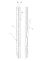
図2は、上記の微粉炭の吹込みに用いられる従来のブローパイプおよびその内張り耐火物層の施工方法を示す断面図である。この図2に示すように従来のブローパイプ1は、筒状の鉄皮2と、その鉄皮2の内側に位置する内張り耐火物層3と、それら鉄皮2および内張り耐火物層3を貫通するランス装入用のガイド管4とを具え、その内張り耐火物層3が耐火材層5と断熱材層6との2層構造とされ、このため内張り耐火物層3を構成する耐火物が、耐火材層5を形成する耐火材と断熱材層6を形成する断熱材とからなっている。
FIG. 2 is a cross-sectional view showing a conventional blow pipe used for blowing the pulverized coal and a method for constructing the lining refractory layer. As shown in FIG. 2, the
ところで上記の微粉炭の燃焼効率を上昇させるためには、送風条件を変更する、具体的には送風温度上昇や酸素付加を実施することが有効であるが、酸素価格は高価であり、送風温度上昇や酸素付加はコスト上昇を招く。また、ランスの取り付け位置やランス形状の変更によって、微粉炭の分散性を上昇させて酸素との反応を促進させる方法もあるが、極度の分散性上昇は、羽口の磨耗や羽口への微粉炭中の溶融灰分の付着を招く。 By the way, in order to increase the combustion efficiency of the above pulverized coal, it is effective to change the blowing conditions, specifically, to raise the blowing temperature or to add oxygen, but the oxygen price is expensive and the blowing temperature Increasing or adding oxygen causes an increase in cost. There is also a method to increase the dispersibility of pulverized coal by changing the lance mounting position and lance shape to promote the reaction with oxygen, but the extreme increase in dispersibility is due to the wear of tuyere and the tuyere It causes adhesion of molten ash in pulverized coal.
こういった制約がある中で、ブローパイプにランスを2本以上備える構造をとる場合も多い(例えば、特許文献1、特許文献2および特許文献3参照)。しかしながら、構造が複雑になるほどブローパイプ内の内張り耐火物の施工が困難となる。
Under such restrictions, the blow pipe often has a structure having two or more lances (see, for example,
上述のように、ブローパイプ内の構造が複雑化している現状にあっては、内張り耐火物の充填不良および、それに伴う外側の鉄皮の赤熱により、ブローパイプの寿命が低下するという問題があった。 As described above, in the present situation where the structure inside the blow pipe is complicated, there is a problem that the life of the blow pipe is reduced due to poor filling of the lining refractory and the accompanying red heat of the outer skin. It was.
また、従来の内張り耐火物の施工方法では、鉄皮2の内周面に最初に断熱材を施工し、それを硬化させて断熱材層6を形成した後、その断熱材層6の内周面に耐火材を施工し、それを硬化させて耐火材層5を形成するという方法であったが、この方法では施工に時間がかかり、作業効率が悪いという問題もあった。
Moreover, in the conventional construction method of the lining refractory, after the heat insulating material is first applied to the inner peripheral surface of the
それゆえ本発明は、前記課題を解決し、寿命を向上させるとともに耐火物の施工効率を向上させるブローパイプおよびブローパイプの内張り耐火物層の施工方法を提供することを目的とする。 SUMMARY OF THE INVENTION Therefore, an object of the present invention is to solve the above-mentioned problems and to provide a blow pipe and a method for constructing a lining refractory layer of a blow pipe that improve the life and improve the construction efficiency of the refractory.
本発明者らは、使用後のブローパイプを回収して解析したところ、断熱材が溶融していることを発見した。断熱材が溶融するのはそれより稼動面側(内側)に施工している耐火材の断熱性が不足していることに起因しており、それゆえ本発明者は、前記課題の解決には耐火物の充填性の向上とともに断熱性の向上が必要であると考え、下記の本発明を想到するに到った。 The present inventors recovered and analyzed the blowpipe after use, and found that the heat insulating material was melted. The heat-insulating material is melted because the heat-insulating property of the refractory material applied to the working surface side (inner side) is insufficient. The improvement of the heat resistance as well as the improvement of the filling property of the refractory is considered, and the present invention described below has been conceived.
すなわち、前記課題を解決する本発明のブローパイプは、筒状の鉄皮と、前記鉄皮の内側に位置する内張り耐火物層と、それら鉄皮および内張り耐火物層を貫通するランス装入用のガイド管とを具え、高炉羽口に接続されるブローパイプにおいて、
前記内張り耐火物層を構成する耐火物が、熱伝導率が0.6W/mK以下であり、Al2O3含有量が48質量%以上で72質量%以下であり、かつ、Al2O3/SiO2の質量比が1.1以上である耐火材からなり、
前記内張り耐火物層が、前記耐火材の層からなる1層構造のものであることを特徴とするものである。
That is, the blowpipe of the present invention that solves the above-mentioned problems is for a lance charging that penetrates the cylindrical iron skin, the lining refractory layer located inside the iron rust, and the iron lining and lining refractory layer. In the blow pipe connected to the blast furnace tuyere,
The refractory constituting the lining refractory layer has a thermal conductivity of 0.6 W / mK or less, an Al 2 O 3 content of 48% by mass or more and 72% by mass or less, and Al 2 O 3 Made of a refractory material having a mass ratio of / SiO 2 of 1.1 or more,
The lining refractory layer has a one-layer structure composed of a layer of the refractory material.
また、前記課題を解決する本発明のブローパイプの内張り耐火物層施工方法は、筒状の鉄皮と、前記鉄皮の内側に位置する内張り耐火物層と、それら鉄皮および内張り耐火物層を貫通するランス装入用のガイド管とを具え、高炉羽口に接続されるブローパイプの、前記内張り耐火物層を施工するに際し、
前記内張り耐火物層を構成する耐火物として、熱伝導率が0.6W/mK以下であり、Al2O3含有量が48質量%以上で72質量%以下であり、かつ、Al2O3/SiO2の質量比が1.1以上である耐火材を用い、
前記内張り耐火物層として、前記耐火材を1層で施工することを特徴とするものである。
Further, the blow pipe lining refractory layer construction method of the present invention that solves the above problems includes a cylindrical iron skin, a lining refractory layer positioned inside the iron skin, and the iron skin and lining refractory layer. When installing the lining refractory layer of the blow pipe connected to the blast furnace tuyere,
As the refractory constituting the lining refractory layer, the thermal conductivity is 0.6 W / mK or less, the Al 2 O 3 content is 48 mass% or more and 72 mass% or less, and Al 2 O 3 Using a refractory material having a mass ratio of / SiO 2 of 1.1 or more,
The refractory material is constructed in one layer as the lining refractory layer.
上述したように、本発明のブローパイプおよびその内張り耐火物層の施工方法では、ブローパイプの鉄皮の内側に内張り耐火物層として耐火材を1層施工するようにしたので、耐火物の充填不良がなくなるとともに、工期の短縮が図られて作業効率が向上した。 As described above, in the blow pipe and the lining refractory layer construction method of the present invention, since one layer of refractory material is constructed as the lining refractory layer inside the blowpipe iron skin, filling with refractory In addition to eliminating defects, the work period was shortened and work efficiency was improved.
また、熱伝導率が0.6W/mK以下と低い耐火材を使用することにより、ブローパイプ内の半径方向の温度勾配が大きくなり、耐火物の充填不良がなくなったことと相俟って、鉄皮が赤熱することがなくなり、ブローパイプの寿命が向上した。 Moreover, by using a refractory material having a thermal conductivity as low as 0.6 W / mK or less, the temperature gradient in the radial direction in the blowpipe is increased, and in combination with the absence of defective refractory filling, The iron skin is no longer red hot and the life of the blowpipe is improved.
さらに、Al2O3/SiO2の質量比が1.1以上であるので耐火材中のAl2O3含有量がSiO2含有量よりも多く、しかもAl2O3含有量が48質量%以上で72質量%以下であることから、耐用温度が高いため、耐火物が溶融することがなくなり、この点でもブローパイプの寿命が向上した。 Furthermore, since the mass ratio of Al 2 O 3 / SiO 2 is 1.1 or more, the Al 2 O 3 content in the refractory material is larger than the SiO 2 content, and the Al 2 O 3 content is 48 mass%. Since it is 72 mass% or less above, since the service temperature is high, the refractory does not melt, and the life of the blowpipe is improved in this respect as well.
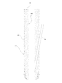
以下、本発明の実施の形態を図面に基づき詳細に説明する。ここに、図1は、本発明のブローパイプおよびその内張り耐火物層の施工方法の一実施形態を示す断面図であり、図中図2と同様の部分はそれと同一の符号にて示す。 Hereinafter, embodiments of the present invention will be described in detail with reference to the drawings. FIG. 1 is a cross-sectional view showing an embodiment of the blow pipe and the lining refractory layer construction method according to the present invention, in which the same parts as those in FIG. 2 are denoted by the same reference numerals.
図1に示すこの実施形態のブローパイプ1は、図2に示す従来のブローパイプ1と同様に高炉羽口に接続されるものであって、筒状の鉄皮2と、その鉄皮2の内側に位置する内張り耐火物層3と、それら鉄皮2および内張り耐火物層3を貫通するランス装入用のガイド管4とを具えているが、その内張り耐火物層3は、従来のブローパイプ1の2層構造と異なり、耐火物として耐火材を用いた耐火材層5のみからなる1層構造とされている。
A
ここで耐火材層5を形成する耐火材は、耐用温度が高いものであると同時に、断熱材としても機能する熱伝導率の低いものであり、具体的には、熱伝導率が0.6W/mK以下であり、Al2O3含有量が48質量%以上で72質量%以下であり、かつ、Al2O3/SiO2の質量比が1.1以上である耐火材である。
Here, the refractory material forming the
そして、この実施形態のブローパイプの内張り耐火物層の施工方法では、図1に示す、筒状の鉄皮2と、その鉄皮2の内側に位置する内張り耐火物層3と、それら鉄皮2および内張り耐火物層3を貫通するランス装入用のガイド管4とを具え、高炉羽口に接続されるブローパイプ1の、その内張り耐火物層3を施工するに際し、その内張り耐火物層3を構成する耐火物として、熱伝導率が0.6W/mK以下であり、Al2O3含有量が48質量%以上で72質量%以下であり、かつ、Al2O3/SiO2の質量比が1.1以上である耐火材を用い、その内張り耐火物層3として、前記耐火材の層5を1層で施工する。
And in the construction method of the lining refractory layer of the blow pipe of this embodiment, the
この実施形態のブローパイプおよびその内張り耐火物層の施工方法によれば、高炉羽口に接続されるブローパイプ1の筒状の鉄皮2の内側に内張り耐火物層3として耐火材層5を1層施工するようにしたから、耐火物の充填不良がなくなった。
According to the construction method of the blow pipe and the lining refractory layer of this embodiment, the
また、この実施形態のブローパイプおよびその内張り耐火物層の施工方法によれば、熱伝導率が0.6W/mK以下と低い耐火材を使用したから、ブローパイプ内の半径方向の温度勾配が大きくなり、耐火物の充填不良がなくなったことと相俟って、鉄皮が赤熱することがなくなり、ブローパイプの寿命が向上した。なお、熱伝導率が0.6W/mKを超えると、ブローパイプ内の半径方向の温度勾配が小さくなり、鉄皮が赤熱してブローパイプの寿命が低下する。 Moreover, according to the construction method of the blow pipe and the lining refractory layer of this embodiment, since the heat conductivity is as low as 0.6 W / mK or less, the temperature gradient in the radial direction in the blow pipe is Combined with the increase in the refractory filling failure, the iron skin is no longer red-hot and the life of the blowpipe is improved. If the thermal conductivity exceeds 0.6 W / mK, the radial temperature gradient in the blow pipe becomes small, the iron skin becomes red hot, and the life of the blow pipe decreases.
さらに、この実施形態のブローパイプおよびその内張り耐火物層の施工方法によれば、Al2O3含有量が48質量%以上で72質量%以下であり、かつ、Al2O3/SiO2の質量比が1.1以上である耐火材を使用したから、ブローパイプ1の使用中に耐火物が溶融することがなくなった。
Furthermore, according to the construction method of the blow pipe and the lining refractory layer of this embodiment, the Al 2 O 3 content is 48% by mass or more and 72% by mass or less, and Al 2 O 3 / SiO 2 Since the refractory material having a mass ratio of 1.1 or more was used, the refractory was not melted during use of the
なお、Al2O3含有量が48質量%未満またはAl2O3/SiO2の質量比が1.1未満の耐火材あるいは断熱材を耐火物として使用すると、耐火物の融点が低く、ブローパイプ1の使用中に耐火物が溶融する。また、Al2O3含有量が72質量%を超えると、ムライト(3Al2O3・2SiO2)よりもAl2O3が多くなるため耐火物の熱伝導率が高くなり、鉄皮が赤熱してブローパイプの寿命が低下する。耐火物の熱伝導率はAl2O3含有量とSiO2含有量とに依存する。これは、例えば緻密質のAl2O3では熱伝導率は36〜38W/mKであり、一方、緻密質のムライトでは熱伝導率は約5W/mKであるからである。
When a refractory material or a heat insulating material having an Al 2 O 3 content of less than 48% by mass or an Al 2 O 3 / SiO 2 mass ratio of less than 1.1 is used as the refractory, the melting point of the refractory is low and blown The refractory melts during use of the
Al2O3含有量およびSiO2含有量の少なくとも一方が異なる5種類の耐火物(耐火材および断熱材)を試作した。これらの耐火物をそれぞれ、水を加えて2分間混練し、成形型内に流し込んで114×230×65mmに成形した。そして1日養生後、脱型し、110℃×24時間乾燥させ、1000℃×3時間熱処理を行って試料とした。これらの試料について、JIS R2251−2:2007 耐火物の熱伝導率の試験方法−第2部:熱線法(平行法)により、1000℃での熱伝導率を測定した。これらの試料のAl2O3含有量(質量%)およびSiO2含有量(質量%)並びに熱伝導率の測定結果を表1に示す。 Five types of refractories (refractory materials and heat insulation materials) having different at least one of Al 2 O 3 content and SiO 2 content were made as trial products. Each of these refractories was added with water, kneaded for 2 minutes, poured into a mold and molded into 114 × 230 × 65 mm. Then, after curing for 1 day, the mold was removed, dried at 110 ° C. for 24 hours, and heat-treated at 1000 ° C. for 3 hours to obtain a sample. With respect to these samples, the thermal conductivity at 1000 ° C. was measured by JIS R2251-2: 2007 Test method for thermal conductivity of refractories—Part 2: Hot wire method (parallel method). Table 1 shows the measurement results of the Al 2 O 3 content (mass%), the SiO 2 content (mass%), and the thermal conductivity of these samples.
次に、外径200mm、内径160mmの鉄皮の内側にこれらの耐火物を80mm(半径分厚さ40mm)施工してブローパイプを形成した。実施例1(図1参照)、実施例2および比較例2〜4は、耐火物として耐火材を1層施工したものである。比較例1(図2参照)は、鉄皮2の内側に耐火物として耐火材と断熱材とを2層に施工したものであり、ここで、稼動面側(内側)が1層目(耐火材層5)、鉄皮側(外側)が2層目(断熱材層6)である。
Next, these refractories were applied 80 mm (radius 40 mm thick) on the inside of an iron skin having an outer diameter of 200 mm and an inner diameter of 160 mm to form a blow pipe. Example 1 (refer FIG. 1), Example 2, and Comparative Examples 2-4 apply 1 layer of refractory materials as a refractory. In Comparative Example 1 (see FIG. 2), a refractory material and a heat insulating material are constructed in two layers as a refractory inside the
サーモグラフィーにより、操業中のブローパイプの鉄皮温度を測定した。また、使用後のブローパイプから耐火物を採取し、顕微鏡にて倍率10倍で溶融した組織の有無の観察を行った。それらの結果を表1に示す。 The iron skin temperature of the blow pipe during operation was measured by thermography. Moreover, the refractory material was extract | collected from the blowpipe after use, and the presence or absence of the melt | dissolved structure | tissue was observed with the microscope at 10 time magnification. The results are shown in Table 1.

表1に示すように、実施例1および実施例2は、何れも鉄皮温度が300℃以下であり、使用後の耐火物組織が健全であった。これに対し従来構造を持つ比較例1では、Al2O3含有量が多く融点は高いものの熱伝導率が高い耐火材を1層目に施工し、Al2O3含有量が少なくAl2O3/SiO2質量比が低い断熱材を2層目に施工したため、鉄皮温度は300℃以下であったものの、使用後耐火物に溶融した組織が観察された。なお、耐火物の溶融は、突発トラブルの原因となり、安定操業を妨げることになるため好ましくない。 As shown in Table 1, in both Examples 1 and 2, the iron skin temperature was 300 ° C. or less, and the refractory structure after use was sound. On the other hand, in Comparative Example 1 having a conventional structure, a refractory material having a high Al 2 O 3 content and a high melting point but a high thermal conductivity was applied to the first layer, and the Al 2 O 3 content was low and Al 2 O Since a heat insulating material having a low 3 / SiO 2 mass ratio was applied in the second layer, the iron skin temperature was 300 ° C. or lower, but a structure melted in the refractory after use was observed. It should be noted that melting of the refractory is not preferable because it causes sudden troubles and hinders stable operation.
比較例2および比較例3は、Al2O3含有量が少ない耐火材を1層だけ施工したものである。比較例1と同様に鉄皮温度は300℃以下であったものの、使用後耐火物に溶融した組織が観察された。比較例4は、Al2O3含有量、Al2O3/SiO2質量比ともに本発明の範囲内であるが、熱伝導率が本発明の範囲より大きいものである。この比較例4では、使用後の耐火物組織は健全であったが、鉄皮温度が351℃と高温になり、使用時に鉄皮が赤熱しているのが観察された。 In Comparative Example 2 and Comparative Example 3, only one layer of a refractory material having a low Al 2 O 3 content was applied. Although the iron skin temperature was 300 ° C. or lower as in Comparative Example 1, a structure melted in the refractory after use was observed. In Comparative Example 4, both the Al 2 O 3 content and the Al 2 O 3 / SiO 2 mass ratio are within the range of the present invention, but the thermal conductivity is larger than the range of the present invention. In Comparative Example 4, the refractory structure after use was healthy, but the iron skin temperature was as high as 351 ° C., and it was observed that the iron skin was red hot during use.
従って上記の結果から、これら実施例1,2のブローパイプによれば、従来のブローパイプと比較して、寿命を向上させるとともに耐火物の施工効率を向上させることができるということが確認された。 Therefore, from the above results, according to the blow pipes of Examples 1 and 2, it was confirmed that the life and the construction efficiency of the refractory can be improved as compared with the conventional blow pipe. .
以上、図示の実施形態に基づき説明したが、本発明は、上記実施形態に限定されるものでなく、特許請求の範囲の記載範囲内で適宜変形し得るものであり、例えば、ランス装入用のガイド管4は、図示例では1本のみ具えるが、特許文献1〜3に記載のように複数本具えていてもよい。
The present invention has been described based on the illustrated embodiment. However, the present invention is not limited to the above-described embodiment, and can be appropriately modified within the scope of the claims, for example, for lance insertion. In the illustrated example, only one
かくして本発明のおよびその内張り耐火物層の施工方法によれば、ブローパイプの鉄皮の内側に内張り耐火物層として耐火材を1層施工するようにしたので、耐火物の充填不良がなくなるとともに、工期の短縮が図られて作業効率が向上した。 Thus, according to the construction method of the present invention and its lining refractory layer, since one layer of refractory material is constructed as the lining refractory layer inside the iron skin of the blowpipe, the filling failure of the refractory is eliminated. The work period was shortened and the work efficiency was improved.
また、熱伝導率が0.6W/mK以下と低い耐火材を使用することにより、ブローパイプ内の半径方向の温度勾配が大きくなり、耐火物の充填不良がなくなったことと相俟って、鉄皮が赤熱することがなくなり、ブローパイプの寿命が向上した。 Moreover, by using a refractory material having a thermal conductivity as low as 0.6 W / mK or less, the temperature gradient in the radial direction in the blowpipe is increased, and in combination with the absence of defective refractory filling, The iron skin is no longer red hot and the life of the blowpipe is improved.
さらに、Al2O3/SiO2の質量比が1.1以上であるので耐火材中のAl2O3含有量がSiO2含有量よりも多く、しかもAl2O3含有量が48質量%以上で72質量%以下であることから、耐用温度が高いため、耐火物が溶融することがなくなり、この点でもブローパイプの寿命が向上した。 Furthermore, since the mass ratio of Al 2 O 3 / SiO 2 is 1.1 or more, the Al 2 O 3 content in the refractory material is larger than the SiO 2 content, and the Al 2 O 3 content is 48 mass%. Since it is 72 mass% or less above, since the service temperature is high, the refractory does not melt, and the life of the blowpipe is improved in this respect as well.
1 ブローパイプ
2 鉄皮
3 耐火物層
4 ガイド管
5 耐火材層
6 断熱材層
DESCRIPTION OF
Claims (2)
前記内張り耐火物層を構成する耐火物が、熱伝導率が0.6W/mK以下であり、Al2O3含有量が48質量%以上で72質量%以下であり、かつ、Al2O3/SiO2の質量比が1.1以上である耐火材からなり、
前記内張り耐火物層が、前記耐火材の層からなる1層構造のものであることを特徴とする、ブローパイプ。 It has a cylindrical iron skin, a lining refractory layer located inside the iron skin, and a guide tube for lance insertion that penetrates the iron skin and the lining refractory layer, and is connected to the blast furnace tuyere In the blowpipe,
The refractory constituting the lining refractory layer has a thermal conductivity of 0.6 W / mK or less, an Al 2 O 3 content of 48% by mass or more and 72% by mass or less, and Al 2 O 3 Made of a refractory material having a mass ratio of / SiO 2 of 1.1 or more,
The blow pipe according to claim 1, wherein the lining refractory layer has a one-layer structure composed of a layer of the refractory material.
前記内張り耐火物層を構成する耐火物として、熱伝導率が0.6W/mK以下であり、Al2O3含有量が48質量%以上で72質量%以下であり、かつ、Al2O3/SiO2の質量比が1.1以上である耐火材を用い、
前記内張り耐火物層として、前記耐火材を1層で施工することを特徴とする、ブローパイプの内張り耐火物層施工方法。 It has a cylindrical iron skin, a lining refractory layer located inside the iron skin, and a guide tube for lance insertion that penetrates the iron skin and the lining refractory layer, and is connected to the blast furnace tuyere When constructing the lining refractory layer of the blowpipe,
As the refractory constituting the lining refractory layer, the thermal conductivity is 0.6 W / mK or less, the Al 2 O 3 content is 48 mass% or more and 72 mass% or less, and Al 2 O 3 Using a refractory material having a mass ratio of / SiO 2 of 1.1 or more,
A method for constructing a lining refractory layer for a blow pipe, wherein the refractory material is constructed in one layer as the lining refractory layer.
Priority Applications (1)
| Application Number | Priority Date | Filing Date | Title |
|---|---|---|---|
| JP2012045467A JP2013181202A (en) | 2012-03-01 | 2012-03-01 | Blow pipe and method for constructing lining refractory layer thereof |
Applications Claiming Priority (1)
| Application Number | Priority Date | Filing Date | Title |
|---|---|---|---|
| JP2012045467A JP2013181202A (en) | 2012-03-01 | 2012-03-01 | Blow pipe and method for constructing lining refractory layer thereof |
Publications (1)
| Publication Number | Publication Date |
|---|---|
| JP2013181202A true JP2013181202A (en) | 2013-09-12 |
Family
ID=49272079
Family Applications (1)
| Application Number | Title | Priority Date | Filing Date |
|---|---|---|---|
| JP2012045467A Pending JP2013181202A (en) | 2012-03-01 | 2012-03-01 | Blow pipe and method for constructing lining refractory layer thereof |
Country Status (1)
| Country | Link |
|---|---|
| JP (1) | JP2013181202A (en) |
Cited By (1)
| Publication number | Priority date | Publication date | Assignee | Title |
|---|---|---|---|---|
| JP7440759B2 (en) | 2020-04-02 | 2024-02-29 | 日本製鉄株式会社 | Damaged tuyere treatment method and refrigerant distribution system |
-
2012
- 2012-03-01 JP JP2012045467A patent/JP2013181202A/en active Pending
Cited By (1)
| Publication number | Priority date | Publication date | Assignee | Title |
|---|---|---|---|---|
| JP7440759B2 (en) | 2020-04-02 | 2024-02-29 | 日本製鉄株式会社 | Damaged tuyere treatment method and refrigerant distribution system |
Similar Documents
| Publication | Publication Date | Title |
|---|---|---|
| JP2008151425A (en) | Repair method of magnesia carbon brick | |
| US10247478B2 (en) | Monolithic refractory structure | |
| JP2013181202A (en) | Blow pipe and method for constructing lining refractory layer thereof | |
| JP5027861B2 (en) | Refractory structure of waste melting furnace | |
| JP5463623B2 (en) | Brick structure of converter bottom blowing tuyere | |
| JP2006300357A (en) | Refractory structure of waste melting furnace | |
| CN101796362B (en) | Tuyere structure of smelting furnace | |
| JP5168080B2 (en) | Unshaped refractories for vertical furnaces | |
| JP5896148B2 (en) | Blast furnace air tuyere | |
| JP6438283B2 (en) | Precast block structure | |
| CN103925786A (en) | Double-pushing-plate high-temperature sintering kiln for producing vanadium-nitrogen alloy | |
| CN211451852U (en) | Ferronickel electric furnace with magnesium-carbon composite furnace lining | |
| CN112458223A (en) | Blast furnace tuyere belt structure | |
| CN110906740A (en) | Ferronickel electric furnace with magnesium-carbon composite furnace lining | |
| WO2013145152A1 (en) | Furnace wall structure of molten metal container and method for constructing furnace wall of molten metal container | |
| CN203396241U (en) | Graphite composite material ramming furnace lining for ferroalloy furnace | |
| KR101429139B1 (en) | Si-SiC FILLER FOR STAVE OF BLAST FURNACE | |
| JP2012122131A (en) | Refractory-lining structure of iron-making vessel | |
| JPH02240207A (en) | Tuyere for blast furnace | |
| JP2004285441A (en) | Brick-laid structure at furnace bottom of converter having bottom-blowing tuyere | |
| CN206160733U (en) | Become slope integral type magnesium carbon brick | |
| JP2001254117A (en) | Metal refining furnace | |
| CN201954941U (en) | Rotary burner at melting furnace slag-discharging end wall | |
| CN201224737Y (en) | Final reducing furnace for non-blast furnace ironmaking | |
| JP2021110483A (en) | Gas blowing plug for molten metal stirring |