JP2013177963A - Method for use of water spray hose - Google Patents
Method for use of water spray hose Download PDFInfo
- Publication number
- JP2013177963A JP2013177963A JP2012264144A JP2012264144A JP2013177963A JP 2013177963 A JP2013177963 A JP 2013177963A JP 2012264144 A JP2012264144 A JP 2012264144A JP 2012264144 A JP2012264144 A JP 2012264144A JP 2013177963 A JP2013177963 A JP 2013177963A
- Authority
- JP
- Japan
- Prior art keywords
- hose
- water
- elastic hose
- internal elastic
- protective cover
- Prior art date
- Legal status (The legal status is an assumption and is not a legal conclusion. Google has not performed a legal analysis and makes no representation as to the accuracy of the status listed.)
- Pending
Links
Images


Classifications
-
- F—MECHANICAL ENGINEERING; LIGHTING; HEATING; WEAPONS; BLASTING
- F16—ENGINEERING ELEMENTS AND UNITS; GENERAL MEASURES FOR PRODUCING AND MAINTAINING EFFECTIVE FUNCTIONING OF MACHINES OR INSTALLATIONS; THERMAL INSULATION IN GENERAL
- F16L—PIPES; JOINTS OR FITTINGS FOR PIPES; SUPPORTS FOR PIPES, CABLES OR PROTECTIVE TUBING; MEANS FOR THERMAL INSULATION IN GENERAL
- F16L11/00—Hoses, i.e. flexible pipes
- F16L11/04—Hoses, i.e. flexible pipes made of rubber or flexible plastics
- F16L11/12—Hoses, i.e. flexible pipes made of rubber or flexible plastics with arrangements for particular purposes, e.g. specially profiled, with protecting layer, heated, electrically conducting
Landscapes
- Engineering & Computer Science (AREA)
- General Engineering & Computer Science (AREA)
- Mechanical Engineering (AREA)
- Rigid Pipes And Flexible Pipes (AREA)
- Joints Allowing Movement (AREA)
- Protection Of Pipes Against Damage, Friction, And Corrosion (AREA)
Abstract
Description
本発明は水道の蛇口などに接続して散水や給水などに使用される散水ホースの使用方法に関するものである。 The present invention relates to a method of using a watering hose that is connected to a faucet or the like for watering or water supply.
散水用又はシャワーへの給水用等に使用される通液ホースは、通常1層であり、中空で、直線状で伸縮性がない。したがって、通常、この通液ホースは用途に合わせて任意の長さに切断して使用されている。 The liquid passing hose used for watering or for supplying water to a shower is usually a single layer, hollow, straight, and not stretchable. Therefore, this liquid passing hose is usually used by cutting to an arbitrary length according to the application.
しかしながら、従来の通液ホースは水道の蛇口から離れた所に散水或は給水する場合は、長い通液ホースを使用しなければならず、ホースが長くなるとホース自体が絡まったり、他の物にひっかかったりして取扱いが不便であり、水の出も悪くなる場合もある。また、長い通液ホースは不使用時の収納に不便であり、通常巻き取って収納される一方、使用時には、散水或は給水をしながらホースを移動したり、手繰り寄せたりするのに大きな力を必要とし、使い勝手が悪い。他方、浴室のシャワーの通液ホースの場合は、長いとシャワーの散水口を壁面の高い所に係止してもホースが床に接して汚れたり、ホースに足が引っ掛かる等するおそれがあり、危険であった。そこで、短いホースでもある程度離れたところまで散水や給水できる伸縮自在な螺旋形通液ホースが提案されている(特許文献1)。 However, if the conventional liquid hose is to spray or supply water away from the water tap, a long liquid hose must be used. It may be caught and inconvenient to handle, and the water output may worsen. In addition, a long liquid hose is inconvenient to store when not in use, and is usually wound up and stored, but when used, it has a great force to move or pull the hose while watering or supplying water. Is not easy to use. On the other hand, in the case of a bathroom shower hose, if it is long, there is a risk that the hose will come into contact with the floor even if the shower sprinkle is locked to a high place on the wall surface, or the foot may get caught in the hose, It was dangerous. In view of this, there has been proposed an elastic spiral liquid flow hose that can sprinkle or supply water to a certain distance even with a short hose (Patent Document 1).
しかしながら、液体が通過可能なホースを伸縮可能なるように螺旋形に成形すると、伸縮動作により、絡まりやすく、螺旋形に保持するのにホースの内部または外部にその螺旋形を保持するための形状保持材を設けることが必要となり、製造コストが高くなる。また、反復使用すると形状保持材を設けても次第に一旦解かれた螺旋形を元の状態に戻すのが困難となる。そこで、本発明は使用時には注水により散水ホースが自動的に所望の長さに伸長され、使用停止時には自動的に元の状態に収縮して復帰する散水ホースの使用方法を提供することを目的とする。 However, if a hose that allows liquid to pass through is formed into a spiral shape so that it can be expanded and contracted, it tends to become entangled due to the expansion and contraction, and the shape is held inside or outside the hose to hold the spiral shape. It is necessary to provide a material, which increases the manufacturing cost. In addition, when it is repeatedly used, it becomes difficult to return the spiral once it has been gradually released to its original state even if a shape-retaining material is provided. Accordingly, an object of the present invention is to provide a method for using a watering hose that is automatically extended to a desired length by water injection during use, and automatically contracts and returns to its original state when use is stopped. To do.
本発明は、先端を閉じた弾性ホースの後端より注水することにより弾性ホースを膨張させるようにし、その直径方向の膨張を外部保護カバーで制限すると、長手方向に伸長することに着目してなされたもので、注水によりホース全長が伸長され、不使用時には元の状態に収縮して復帰する散水ホースの使用方法を提供するものであり、注水により径方向膨張するとともに長手方向に伸長可能な小径内部弾性ホースと、該弾性ホースの外側で径方向膨張を制限する大径の円筒形をなし、前記弾性ホースの外側に蛇腹状に被さり、弾性ホースの伸長とともにその伸長全体に渡る非拡張性外部保護カバーとからなる伸縮性二層散水ホースを用いる方法であって、二層散水ホースの先端に散水ノズル付きストップ栓を設ける一方、後端に水道蛇口等に連結する連結具を設け、先端のストップ栓を閉じた状態で後端から連結具を介して内部弾性ホース内に注水することにより、内部弾性ホースを直径方向に膨張させ、外部非拡張性ホースにその直径方向の膨張を制限させて前方への伸長し、前記外部保護カバーの蛇腹状態を前方に拡張して内部弾性ホースと外部保護カバーとは棒状一体化して散水準備工程と、この状態で内部弾性ホースに注水するとともに、先端ストップの開放により散水ノズルから散水する散水工程と、内部弾性ホースへの注水を停止するとともに、先端ストップ栓の開放により拡張された内部弾性ホースとともに外部保護カバーを収縮させる収納工程からなることを特徴とする。 The present invention is made by paying attention to the fact that the elastic hose is inflated by pouring water from the rear end of the elastic hose with the tip closed, and is expanded in the longitudinal direction when the expansion in the diametrical direction is limited by the external protective cover. In addition, it provides a method of using a watering hose that expands the entire length of the hose due to water injection and contracts and returns to its original state when not in use. An internal elastic hose and a large-diameter cylindrical shape that restricts expansion in the radial direction outside the elastic hose, and covers the outside of the elastic hose in a bellows shape. A method using a stretchable two-layer watering hose consisting of a protective cover, which is provided with a stop stopper with a watering nozzle at the tip of the two-layer watering hose, and a water faucet at the rear end. A connecting tool is provided, and the inner elastic hose is inflated in the diametrical direction by pouring water into the internal elastic hose from the rear end through the connecting tool in a state in which the stop stopper at the front end is closed, so that the external non-expandable hose is expanded. The expansion in the diametrical direction is restricted to extend forward, the bellows state of the external protective cover is expanded forward, the internal elastic hose and the external protective cover are integrated into a rod shape, and the watering preparation step is performed in this state. Water is injected into the elastic hose, the sprinkling process is performed by spraying from the sprinkling nozzle by opening the tip stop, water injection to the internal elastic hose is stopped, and the external protective cover is contracted together with the internal elastic hose expanded by opening the tip stop stopper It is characterized by comprising a storing step.
本発明によれば、散水ホースは、常態では全体に収縮した状態で、蛇腹状に収縮した外部布製ホース2内部に細長い内部弾性ホース1が挿入されている(図1)が、この状態で内部弾性ホースの先端を閉じて後端より注水すると、細長い収縮した内部弾性ホース内に水が充満し、直径方向に膨張するが、外部布製ホースにより直径方向の膨張が制限されるので、外部布ホースに沿って外部布ホースの蛇腹状の収縮を拡張しながら長手方向に伸長し(図2(1))、最終的に、内部弾性ホースが全長に伸び、外部布製ホースと一体となって棒状になると、通常の1層中空ホース同様の散水可能状態となる(図3)。この状態で注水を継続しつつ先端ストップ栓3を開放すると、散水ノズル31から散水可能である(図4)。散水が終了すると、先端ストップ栓3を開放したまま注水を停止すると、拡張された内部弾性ホースの収縮圧により内部水を散水ノズル31から放水しつつ外部布製ホース2とともに内部弾性ホースが収縮し(図2(2))、元の状態に復帰する(図1)。したがって、使用時に長いホースを解放して不使用時には巻き戻す作業をすることがない。
According to the present invention, the watering hose is normally contracted in its entirety, and an elongated internal
次に図面に基づき本発明の具体的な実施形態に対して詳細に説明する。
本発明で使用する伸縮性二層散水ホースの基本形態の一例を図面に基づいて詳細に説明する。先端11に散水ノズル31付きストップ栓3を有する一方、後端12に水道蛇口5に連結する連結具4を有し、先端を閉じた状態で注水により径方向膨張するとともに長手方向に伸長可能な水風船様弾性ホース1と、該弾性ホース1の径方向膨張を制限する所定直径の円筒形を有し、前記弾性ホースの伸長時の全長に渡る非拡張性布製ホース2とから二層構造を構成してなる。
Next, specific embodiments of the present invention will be described in detail with reference to the drawings.
An example of the basic form of the stretchable two-layer watering hose used in the present invention will be described in detail with reference to the drawings. While having the stop stopper 3 with the
内部弾性ホース1は天然ゴムを主成分とする以下の組成からなり、以下の物性及びその近傍の物性を有する肉厚1〜3mm、内径8〜15mmのゴムチューブで、直径16〜30mmまで非破裂耐性を有し、内部水圧により、径方向2倍程度に口径面積4〜5倍に膨張させ、長手方向に、2〜5倍、好ましくは2〜3倍延伸させることが可能で以下の組成からなる。
組成:全固形分:61.5%以上、乾燥ゴム分:50%以上、非ゴム成分:2.0%以下、全アンモニア含有量:0.60%以上、水相中アンモニア含有量:2.0%以下、ラテックスpH:11.0以下、揮発性脂肪酸数(VFA):0.20以上、機械的安定時間@55%TS(BEC)850以上、マグネシウム含有量:30ppm以下
物性:線密度(LD):1100〜1200[dtex]、1000〜1100[D];断裂力(BF):>90[N];断裂強度:>8.00[cN/dtex],>9.00[g/D],
断裂強度係数(CV):<3.00%、断裂伸長率(EAB):14.0%以上;断裂伸長率係数(CV):8.00%以下;4.0[cN/dtex]時の負荷伸長率5.0以上;
熱収縮率(HAS):7.5%以上;含油率(FOY)0.55%以上;IM(intermingling):5[knots/m]
The internal
Composition: total solid content: 61.5% or more, dry rubber content: 50% or more, non-rubber component: 2.0% or less, total ammonia content: 0.60% or more, ammonia content in aqueous phase: 2. 0% or less, latex pH: 11.0 or less, number of volatile fatty acids (VFA): 0.20 or more, mechanical stability time @ 55% TS (BEC) 850 or more, magnesium content: 30 ppm or less Physical property: linear density ( LD): 1100 to 1200 [dtex], 1000 to 1100 [D]; Breaking force (BF):> 90 [N]; Rupture strength:> 8.00 [cN / dtex],> 9.00 [g / D ],
Rupture strength coefficient (CV): <3.00%, Rupture elongation rate (EAB): 14.0% or more; Rupture elongation rate coefficient (CV): 8.00% or less; 4.0 [cN / dtex] Load elongation rate of 5.0 or more;
Heat shrinkage (HAS): 7.5% or more; Oil content (FOY): 0.55% or more; IM (intermingling): 5 [knots / m]
内部弾性ホースの耐圧性能を向上させるために、上記組成の弾性ホースを内側にし、その外側を高密度ポリマーで被覆するように形成するのが好ましい。 In order to improve the pressure resistance performance of the internal elastic hose, it is preferable to form the elastic hose having the above composition on the inside and coat the outside with a high-density polymer.
外部保護カバー2は常態では長手方向に内部弾性ホースの膨張許容径16〜30mmを有する円筒形状で、直径方向には非拡張性で、内部弾性ホースの膨張を制限可能である一方、長手方向におよそ3倍伸長可能な蛇腹状のポリエステル繊維布からなるホースである。
The outer
本発明の伸縮性二層散水ホースは、常態では蛇腹状に収縮した前記布製ホース1内部に収縮した前記弾性ホース1が挿入されているが、先端を閉じた状態で後端からの注水時には内部弾性ホース1は水風船様に直径方向に膨張するとともに、外側布製ホース2にその直径方向の膨張が制限されて前方への伸長可能で、前記布製ホース2の蛇腹状態を前方に拡張して送進し、内部弾性ホース1の長手方向全長伸長時には内部弾性ホース1と外部布製ホース2とは棒状一体化し、この状態では先端ストップ栓3の開放により散水ノズル31から散水可能である一方、注水を停止するとともに、先端ストップ栓3の開放により拡張された内部弾性ホースの収縮圧により内部水を散水ノズル31から放水しつつ外部布製ホース2とともに内部弾性ホースが収縮する。
In the stretchable two-layer watering hose of the present invention, the
したがって、本発明の伸縮性二層散水ホースは、常態では全体に収縮した状態で、蛇腹状に収縮した外部布製ホース2内部に細長い弾性ホース1が挿入され、先端11には散水ノズル31を有するストップ栓3が設けられ、後端12には水道蛇口5に連結する連結具4を有している(図1)が、この状態で内部弾性ホースの先端のストップ栓3を閉じて後端より注水すると、細長い収縮した内部弾性ホース1内に水が充満し、直径方向に膨張するが、外部布製ホースにより直径方向の膨張が制限されるので、外部布ホース2に沿って外部布製ホースの蛇腹状の収縮を拡張しながら長手方向に伸長する(図2(1))。最終的に、内部弾性ホースが全長に伸び、外部布製ホースと一体となって棒状になると、通常の1層中空ホース同様のストップ栓3の開放により散水ノズル31から散水可能状態となる(図3)。この状態で注水を継続しつつ先端ストップ栓3を開放すると、散水ノズル31から散水される(図4)。散水が終了すると、先端ストップ栓3を開放したまま注水を停止すると、拡張された内部弾性ホースの収縮圧により内部水を散水ノズル31から放水しつつ外部布製ホース2とともに内部弾性ホースが収縮し(図2(2))、元の状態まで復帰するとともにホース内部の水はほとんど放水されるので取り扱いが軽量となる(図1)。
Therefore, the stretchable two-layer watering hose of the present invention is normally contracted as a whole, and the elongated
(実施例1)
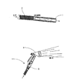
以下、本発明の具体例に基づいて説明する。 図5、図6に示す水道ホースは、ホース体とホース体の両端部に設置した一対の接続部材101Aと101Bを含む。ホース体は内部弾性ホース103と保護カバー106を含む。内部弾性ホース103はゴムホース、エマルジョンホース又はゴムとエマルジョンを混合した材料で構成したホースである。 本発明においては、内部弾性ホースは膨張時の破裂を防止するために高密度ポリマー層を外側に形成した二層弾性ホースを用いる。
Example 1
Hereinafter, description will be made based on specific examples of the present invention. The water supply hose shown in FIGS. 5 and 6 includes a hose body and a pair of connecting members 101A and 101B installed at both ends of the hose body. The hose body includes an internal
保護カバー106は内部弾性ホース103をカバーしており、前後2セットの接続部材の間にあり、その両端は内部弾性ホース103の両端と連接している。保護カバー106の長さは内部弾性ホース103より長い。具体的に、保護カバー106は、その長さが内部弾性ホース103の2〜5倍で、内径が内部弾性ホース103より少し大きいな布保護カバーである。 内部弾性ホース103は弾力性があるため、内部に水圧がある場合径方向にも膨張して増大するが、保護カバーの制限により、長手方向に伸長する。すなわち、この時、保護カバー106の役割は、内部弾性ホース103の径方向膨張を防止する内部弾性ホース103を長く伸ばすことを促進することである。内部弾性ホース103を長く伸ばしやすくするために、保護カバー106は内部弾性ホース103の外に均一の折り目を形成し、蛇腹状になっている。
The
上述の接続部材は変径ジョイント102、螺合部材101A又はB、パッドカバー105及びパッドカバー105の外側に設置したファスナー部材104を含む。一方の螺合部材101は漏斗状の変径ジョイント102の大径部102Aと連接し、変径ジョイント102の環状フランジ部121が螺合部材101Aに嵌まり込んで底部から小径部102Bが突出している。さらに具体的に、上述の螺合部材101A又はBは螺合連接方式を採用しているので散水ホース間の接続設置に便利である。
The connecting member includes the variable diameter joint 102, the screwing member 101A or B, the
内部弾性ホース103の端部は変径ジョイント102の小径部102Bに嵌め込まれ、即ち、内部弾性ホース103は弾性力で変径ジョイント102の小径部102Bの外壁に緊密に嵌められる。パッドカバー105とファスナー部材104は互いに協同するロック装置であり、共に内部弾性ホース103の外側に嵌められる。ファスナー部材104はパッドカバー105を緊密に固定し、パッドカバー105の内側における内部弾性ホース103と変径ジョイント102の小径部102Bを押え、内部弾性ホース103と変径ジョイント102とが離れるのを防止する。ここのパッドカバー105は具体的にゴムパッドカバーであるのが好ましく、ファスナー部材104は、具体的にパッドカバー105外側を緊密に嵌める金属のロッキングファスナーであるのが好ましい。ファスナー部材104で直接に内部弾性ホースを固定すれば内部弾性ホース103の破れ又は破断を招きやすいので、ゴムパッドカバー105を介してこの欠陥を克服することができ、しかも固定した後にスリップ防止効果に優れ、外れにくくなる。ゴムパッドカバー外端の外壁にロック溝を設けており、ロック溝の位置は、内部弾性ホース103を変径ジョイント102の小径部に嵌める位置にある。ファスナー部材104はロック溝にロックされる。内部弾性ホースの両端部に連接している2つの接続部材のうち、1つの接続部材の螺合部材101にメスネジを設け、 もう1つの接続部材の変形ジョイント102の大径部102Aにオスネジを設け、メスネジ付きの螺合部材101Aをオスネジ付きの変形ジョイントの大径部102Aに螺合させることができる。両端の螺合101Aと101Bがそれぞれ雄ネジと雌ネジになっている目的は、全体の水道ホースを独立して使用することができるだけではなく、セクションホースとして何本かを互いに接合して延長して使用することもできるからである。
The end portion of the internal
上述のパッドカバー105と金属ファスナー部材104は内部弾性ホース103と保護カバー106の外側をカバーし、保護カバー106の端部は内部弾性ホース103と変形ジョイント102の小径部まで伸ばしてもよい。ファスナー部材104はパッドカバー105をロックし、且つパッドカバー105内の変径ジョイント102、内部弾性ホース103と保護カバー106を押えて固定するようにしてもよい。
The
(実施例2)
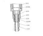
図7及び図8は樹脂にて一体的に形成された変形ジョイント202を使用するものであり、ストッパ栓211を備える螺合部材201と螺合する螺合部を有する大径部202Aと、内部弾性ホースと接続される小径部202Bと、小径部に接続された内部弾性ホース端部を覆うパッドカバー205を緊締する筒状のファスナー部材204と螺合する螺合部を備える。詳しくは螺合部材201は雌ネジを有する一方、大径部202Aの螺合部には雄ネジが設けられて互に螺着されるととに、ファスナー部材205は内部に雌ネジを有する一方、小径部202Bの上部に雄ネジ203が設けられて互いに螺着される。小径部202Bには先端に膨出部と中腹に二重の係合線を有し、内部弾性ホース103の係合時の抜け落ちを防止し、その弾性ホースの係合部の上から環状パッドカバー205を被せ、その上で筒状のファスナー部材204を変径ジョイント202に螺合させて内部弾性ホース103を小径部202Bに緊締するとともに保護カバー106の先端を小径部202Bと内部弾性ホースの上部に取り込むようになっている。その他は、実施例1と同様であるので同一部材には同一番号を付して説明を省略する。
(Example 2)
7 and 8 use a deformable joint 202 integrally formed of resin, and includes a large-
101・・・螺合部材
・ 202・・・変径ジョイント
102A、202A・・・大径部
102B、202B・・・小径部
1、103・・・内部弾性ホース
・ 204・・・ファスナー部材
・ 205・・・パッドカバー
2、106・・・保護カバー
DESCRIPTION OF
Claims (2)
Applications Claiming Priority (2)
| Application Number | Priority Date | Filing Date | Title |
|---|---|---|---|
| CN2012200690234U CN202442051U (en) | 2012-02-28 | 2012-02-28 | Water pipe |
| CN201220069023.4 | 2012-02-28 |
Publications (1)
| Publication Number | Publication Date |
|---|---|
| JP2013177963A true JP2013177963A (en) | 2013-09-09 |
Family
ID=46823502
Family Applications (4)
| Application Number | Title | Priority Date | Filing Date |
|---|---|---|---|
| JP2012007302U Expired - Fee Related JP3181596U (en) | 2012-02-28 | 2012-12-03 | Elastic double-layer watering hose |
| JP2012264144A Pending JP2013177963A (en) | 2012-02-28 | 2012-12-03 | Method for use of water spray hose |
| JP2013000788U Ceased JP3183172U (en) | 2012-02-28 | 2013-02-15 | Elastic double-layer watering hose |
| JP2013004600U Expired - Fee Related JP3186680U (en) | 2012-02-28 | 2013-08-08 | Connection structure of stretchable two-layer watering hose |
Family Applications Before (1)
| Application Number | Title | Priority Date | Filing Date |
|---|---|---|---|
| JP2012007302U Expired - Fee Related JP3181596U (en) | 2012-02-28 | 2012-12-03 | Elastic double-layer watering hose |
Family Applications After (2)
| Application Number | Title | Priority Date | Filing Date |
|---|---|---|---|
| JP2013000788U Ceased JP3183172U (en) | 2012-02-28 | 2013-02-15 | Elastic double-layer watering hose |
| JP2013004600U Expired - Fee Related JP3186680U (en) | 2012-02-28 | 2013-08-08 | Connection structure of stretchable two-layer watering hose |
Country Status (2)
| Country | Link |
|---|---|
| JP (4) | JP3181596U (en) |
| CN (1) | CN202442051U (en) |
Cited By (3)
| Publication number | Priority date | Publication date | Assignee | Title |
|---|---|---|---|---|
| JP2017129228A (en) * | 2016-01-21 | 2017-07-27 | 株式会社タカギ | Hose structure |
| JP2017190863A (en) * | 2016-04-15 | 2017-10-19 | アイメディア株式会社 | Exterior member for rubber hose of elastic raw material |
| WO2018198170A1 (en) * | 2017-04-24 | 2018-11-01 | 株式会社タカギ | Hose structure |
Families Citing this family (7)
| Publication number | Priority date | Publication date | Assignee | Title |
|---|---|---|---|---|
| US8757213B2 (en) | 2011-11-04 | 2014-06-24 | Blue Gentian, Llc | Commercial hose |
| US10174870B2 (en) | 2011-11-04 | 2019-01-08 | Telebrands Corp. | Expandable and contractible garden hose |
| JP3183804U (en) * | 2013-03-21 | 2013-05-30 | 秀福銅器股▲ふん▼有限公司 | Telescopic hose structure |
| LT3146251T (en) * | 2014-05-20 | 2019-04-25 | Paolo De Nora | Extensible hose and hose assembly |
| CN110094588A (en) * | 2018-01-31 | 2019-08-06 | 史宇杰 | Flexible water pipe |
| CN108999577B (en) * | 2018-10-24 | 2024-04-12 | 西南石油大学 | Variable-diameter double-layer pipe connecting device for solid-state fluidization exploitation of hydrate |
| US20220082193A1 (en) * | 2019-05-07 | 2022-03-17 | Aiqi Zheng | System for a Self-Recoiling Hose |
Family Cites Families (7)
| Publication number | Priority date | Publication date | Assignee | Title |
|---|---|---|---|---|
| JPS4914510U (en) * | 1972-05-10 | 1974-02-06 | ||
| JPS5829337Y2 (en) * | 1979-05-18 | 1983-06-27 | 住友ゴム工業株式会社 | Gas rubber tube with protective cover |
| JPH0236687U (en) * | 1988-09-02 | 1990-03-09 | ||
| DE19533553C2 (en) * | 1995-09-11 | 1998-01-29 | Rasmussen Gmbh | Device for clamping a hose end section pushed onto a pipe end section |
| JPH09217877A (en) * | 1996-02-14 | 1997-08-19 | Tokai Rubber Ind Ltd | Resin tube with protector |
| JP3059801U (en) * | 1998-12-11 | 1999-07-13 | 大同特殊工業株式会社 | Flexible tube for pipe connection |
| JP3569840B2 (en) * | 1999-10-29 | 2004-09-29 | 株式会社トヨックス | Fitting and installation method of pressure-resistant hose using the fitting |
-
2012
- 2012-02-28 CN CN2012200690234U patent/CN202442051U/en not_active Expired - Lifetime
- 2012-12-03 JP JP2012007302U patent/JP3181596U/en not_active Expired - Fee Related
- 2012-12-03 JP JP2012264144A patent/JP2013177963A/en active Pending
-
2013
- 2013-02-15 JP JP2013000788U patent/JP3183172U/en not_active Ceased
- 2013-08-08 JP JP2013004600U patent/JP3186680U/en not_active Expired - Fee Related
Cited By (4)
| Publication number | Priority date | Publication date | Assignee | Title |
|---|---|---|---|---|
| JP2017129228A (en) * | 2016-01-21 | 2017-07-27 | 株式会社タカギ | Hose structure |
| JP2017190863A (en) * | 2016-04-15 | 2017-10-19 | アイメディア株式会社 | Exterior member for rubber hose of elastic raw material |
| WO2018198170A1 (en) * | 2017-04-24 | 2018-11-01 | 株式会社タカギ | Hose structure |
| JPWO2018198170A1 (en) * | 2017-04-24 | 2020-01-16 | 株式会社タカギ | Hose structure |
Also Published As
| Publication number | Publication date |
|---|---|
| JP3181596U (en) | 2013-02-14 |
| CN202442051U (en) | 2012-09-19 |
| JP3183172U (en) | 2013-05-09 |
| JP3186680U (en) | 2013-10-17 |
Similar Documents
| Publication | Publication Date | Title |
|---|---|---|
| JP3183172U (en) | Elastic double-layer watering hose | |
| JP3187003U (en) | Telescopic hose | |
| EP2851598A1 (en) | Expandable hose assembly | |
| US10591098B2 (en) | Garden hose with metal sheath | |
| ITPD960057U1 (en) | TELESCOPIC AUCTION LOCKING DEVICE | |
| CN103791179B (en) | Extensible hose | |
| JP3183172U7 (en) | ||
| WO2016045230A2 (en) | Automatically extending and expanding water pipe of extended service life | |
| AU2015100607A4 (en) | Water Hose | |
| WO2018133432A1 (en) | Telescopic pipe | |
| JP3180336U (en) | Elastic double-layer watering hose | |
| JP2016223623A (en) | Flexible two-layer water spray hose | |
| US10393291B2 (en) | Expandable water hose assembly | |
| KR200487748Y1 (en) | male coupling of fire hose | |
| TWM506913U (en) | Telescopic water pipe | |
| JP3183804U (en) | Telescopic hose structure | |
| EP2628988A1 (en) | Water hose | |
| US1824492A (en) | Wall fixture attaching means | |
| JP5313520B2 (en) | Fluid barrier bag | |
| CN203453655U (en) | Extensible hose with valve | |
| CN105650385A (en) | A fast-connection structure of water hose and rigid joint | |
| US1205987A (en) | Hose attachment. | |
| CN203757226U (en) | Fire coupling | |
| CN103791187B (en) | Fire coupling | |
| US20200158269A1 (en) | Extensible and retractable hose |