JP2013174855A - Head-up display device - Google Patents
Head-up display device Download PDFInfo
- Publication number
- JP2013174855A JP2013174855A JP2012133379A JP2012133379A JP2013174855A JP 2013174855 A JP2013174855 A JP 2013174855A JP 2012133379 A JP2012133379 A JP 2012133379A JP 2012133379 A JP2012133379 A JP 2012133379A JP 2013174855 A JP2013174855 A JP 2013174855A
- Authority
- JP
- Japan
- Prior art keywords
- display
- light
- display element
- hot mirror
- liquid crystal
- Prior art date
- Legal status (The legal status is an assumption and is not a legal conclusion. Google has not performed a legal analysis and makes no representation as to the accuracy of the status listed.)
- Pending
Links
- 239000000758 substrate Substances 0.000 claims description 20
- 238000005286 illumination Methods 0.000 claims description 11
- 239000004020 conductor Substances 0.000 claims description 5
- 238000007599 discharging Methods 0.000 claims 2
- 230000007257 malfunction Effects 0.000 abstract description 6
- 239000004973 liquid crystal related substance Substances 0.000 description 62
- 239000011521 glass Substances 0.000 description 6
- 239000000463 material Substances 0.000 description 6
- 230000035515 penetration Effects 0.000 description 6
- 229920003002 synthetic resin Polymers 0.000 description 6
- 239000000057 synthetic resin Substances 0.000 description 6
- 230000017525 heat dissipation Effects 0.000 description 5
- 229910052782 aluminium Inorganic materials 0.000 description 4
- XAGFODPZIPBFFR-UHFFFAOYSA-N aluminium Chemical compound [Al] XAGFODPZIPBFFR-UHFFFAOYSA-N 0.000 description 4
- 239000007769 metal material Substances 0.000 description 3
- 230000002093 peripheral effect Effects 0.000 description 3
- 239000004925 Acrylic resin Substances 0.000 description 2
- 229920000178 Acrylic resin Polymers 0.000 description 2
- 230000003287 optical effect Effects 0.000 description 2
- 230000010287 polarization Effects 0.000 description 2
- 239000002390 adhesive tape Substances 0.000 description 1
- 230000005540 biological transmission Effects 0.000 description 1
- 238000000151 deposition Methods 0.000 description 1
- 230000000694 effects Effects 0.000 description 1
- 239000000446 fuel Substances 0.000 description 1
- 238000000034 method Methods 0.000 description 1
- 238000001579 optical reflectometry Methods 0.000 description 1
- 230000000149 penetrating effect Effects 0.000 description 1
- 229920000515 polycarbonate Polymers 0.000 description 1
- 239000004417 polycarbonate Substances 0.000 description 1
- 239000011347 resin Substances 0.000 description 1
- 229920005989 resin Polymers 0.000 description 1
- 238000007740 vapor deposition Methods 0.000 description 1
Images

Abstract
Description
本発明は、表示器が発した表示光を車両のフロントガラス等の投影部材に投影し、観察者に対し虚像表示を行うヘッドアップディスプレイ装置に関するものである。 The present invention relates to a head-up display device that projects display light emitted from a display onto a projection member such as a windshield of a vehicle and displays a virtual image to an observer.
従来より、この種のヘッドアップディスプレイ装置にあっては、例えば下記特許文献1に記載のごとく、車両のフロントガラス(投影部材)に表示器からの表示光を投射して虚像表示を行うものが知られている。 Conventionally, in this type of head-up display device, for example, as described in Patent Document 1 below, a device that projects a display light from a display on a windshield (projection member) of a vehicle to display a virtual image. Are known.
この特許文献1に記載のヘッドアップディスプレイ装置は、車両のインストルメントパネル(以下、インパネと言う)内部に取り付けられており、表示光を発する表示器(液晶表示器)と、この液晶表示器が発する表示光を投影部材側へと反射させるための凹面鏡からなる反射部材と、液晶表示器と反射部材とを収容するハウジングとを備え、反射部材によって反射された表示光をハウジングに形成された透光部を通じて投影部材に投影して観察者(運転者)に対し虚像の表示を行うものである。 The head-up display device described in Patent Document 1 is attached to an interior of an instrument panel (hereinafter referred to as an instrument panel) of a vehicle, and a display (liquid crystal display) that emits display light, A reflecting member made of a concave mirror for reflecting the emitted display light toward the projection member, and a housing for housing the liquid crystal display and the reflecting member, and the display light reflected by the reflecting member is formed in the housing. A virtual image is displayed to an observer (driver) by projecting onto a projection member through an optical part.
そして、この場合、液晶表示器として、所定の配線パターンが施された配線基板と、この配線基板上に実装された発光ダイオードからなる光源と、この光源からの照明光を透過して表示光を形成する(発する)ように光源の前方側に位置する液晶表示素子(表示素子)と、この液晶表示素子と離間するように液晶表示素子の前方側に配置されるホットミラーと、配線基板と光源と液晶表示素子とホットミラーとを収納保持するアルミニウムからなるケース体(保持部材)とが設けられている。 In this case, as a liquid crystal display, a wiring board on which a predetermined wiring pattern is applied, a light source composed of a light emitting diode mounted on the wiring board, and illumination light from the light source is transmitted to transmit display light. A liquid crystal display element (display element) positioned on the front side of the light source to form (emerge), a hot mirror disposed on the front side of the liquid crystal display element so as to be separated from the liquid crystal display element, a wiring board, and a light source And a case body (holding member) made of aluminum for storing and holding the liquid crystal display element and the hot mirror.
ホットミラーは、液晶表示素子が発する可視光線からなる表示光を効率よく反射部材側へと透過させるとともに、ハウジングの透光部並びに反射部材を介して液晶表示器側へと照射する太陽光(外光)の一部を吸収する特性を有している。また、ケース体には、ホットミラーの形状に対応するように開口形成されホットミラーを外部に臨ませるための前面開口部が形成され、液晶表示素子が発する可視光線からなる表示光は、この前面開口部を通じて反射部材へと至る。 The hot mirror efficiently transmits display light composed of visible light emitted from the liquid crystal display element to the reflecting member side, and also irradiates the liquid crystal display side with sunlight (external light) through the light transmitting portion of the housing and the reflecting member. Light). Further, the case body has an opening formed so as to correspond to the shape of the hot mirror and a front opening for facing the hot mirror to the outside is formed, and the display light composed of visible light emitted from the liquid crystal display element is It reaches the reflecting member through the opening.
上述した特許文献1に記載のヘッドアップディスプレイ装置の場合、ケース体の前面開口部を塞ぐようにホットミラーが配置され、このホットミラーの背後側に位置する液晶表示素子がケース体内部に収納保持された構成となっている。つまり、このことは、ホットミラーと液晶表示素子との間に形成される空間領域が密閉された密閉空間であることを意味している。 In the case of the head-up display device described in Patent Document 1 described above, a hot mirror is disposed so as to close the front opening of the case body, and the liquid crystal display element located behind the hot mirror is stored and held inside the case body. It has been configured. That is, this means that the space region formed between the hot mirror and the liquid crystal display element is a sealed space.
ところで、ヘッドアップディスプレイ装置がインパネ内部に取り付けられた状態では、太陽光(外光)の一部がハウジングの透光部並びに反射部材を経て液晶表示器側(ホットミラー側)へと照射されることが考えられる。この場合、ホットミラーへの外光照射に伴いホットミラーが高温状態となり、ホットミラーと液晶表示素子(表示素子)との間に形成される密閉空間に熱がこもる(滞留する)という問題がある。そして、このように密閉空間に熱がこもると、当該熱の影響を受けて液晶表示素子の誤動作を招く虞がある。
そこで本発明は、前述の課題に対して対処するため、表示素子が誤動作する虞のないヘッドアップディスプレイ装置の提供を目的とするものである。
By the way, in a state where the head-up display device is attached to the inside of the instrument panel, a part of sunlight (external light) is irradiated to the liquid crystal display side (hot mirror side) through the translucent part and the reflecting member of the housing. It is possible. In this case, there is a problem that the hot mirror becomes a high temperature state with external light irradiation to the hot mirror, and heat is trapped (stays) in a sealed space formed between the hot mirror and the liquid crystal display element (display element). . If heat is trapped in the sealed space in this way, the liquid crystal display element may malfunction due to the influence of the heat.
Accordingly, an object of the present invention is to provide a head-up display device that does not cause a malfunction of a display element in order to cope with the above-described problems.
本発明は、表示光を発する表示器と、前記表示光を反射させる反射部材と、前記表示器並びに前記反射部材を収容するハウジングとを備え、前記表示器として、前記表示光を発する表示素子と、前記表示素子と離間するように前記表示素子の前方側に配置されるホットミラーと、前記表示素子及び前記ホットミラーを配設するケース部材とが設けられ、前記反射部材によって反射された前記表示光を前記ハウジングに形成された透光部を通じて投影部材に投影して観察者に対し表示を行うヘッドアップディスプレイ装置において、前記ケース部材は、前記表示素子と前記ホットミラーとの間に位置する基部を備えるとともに、前記基部には、外光の一部が前記透光部並びに前記反射部材を経て前記ホットミラーへと照射されることに伴い前記表示素子と前記ホットミラーとの間に滞留する熱を前記ケース部材の外部へと放出するための熱放出部が形成されていることを特徴とする。 The present invention includes a display that emits display light, a reflective member that reflects the display light, a housing that houses the display and the reflective member, and the display element that emits the display light as the display. The display reflected by the reflecting member is provided with a hot mirror disposed on the front side of the display element so as to be separated from the display element, and a case member for disposing the display element and the hot mirror. In a head-up display device that displays light to an observer by projecting light onto a projection member through a light-transmitting portion formed in the housing, the case member is a base portion located between the display element and the hot mirror And a part of external light is irradiated on the hot mirror through the light transmitting part and the reflecting member. Wherein the heat sink for releasing the heat staying outside of the case member between the 示素Ko and the hot mirror is formed.
また本発明は、表示光を発する表示器と、前記表示光を反射させる反射部材と、前記表示器並びに前記反射部材を収容するハウジングとを備え、前記表示器として、前記表示光を発する表示素子と、前記表示素子と離間するように前記表示素子の前方側に配置される偏光部材と、前記表示素子及び前記偏光部材を配設するケース部材とが設けられ、前記反射部材によって反射された前記表示光を前記ハウジングに形成された透光部を通じて投影部材に投影して観察者に対し表示を行うヘッドアップディスプレイ装置において、前記ケース部材は、前記表示素子と前記偏光部材との間に位置する基部を備えるとともに、前記基部には、外光の一部が前記透光部並びに前記反射部材を経て前記偏光部材へと照射されることに伴い前記表示素子と前記偏光部材との間に滞留する熱を前記ケース部材の外部へと放出するための熱放出部が形成されていることを特徴とする。 The present invention also includes a display device that emits display light, a reflective member that reflects the display light, a housing that houses the display device and the reflective member, and the display device that emits the display light as the display device. And a polarizing member disposed on the front side of the display element so as to be separated from the display element, and a case member for disposing the display element and the polarizing member, and the reflection member being reflected by the reflecting member In a head-up display device that projects display light onto a projection member through a translucent part formed in the housing to display to an observer, the case member is located between the display element and the polarizing member. A base portion, and the base portion is irradiated with a part of external light through the light transmitting portion and the reflecting member to the polarizing member. Wherein the heat sink for releasing heat accumulated between the polarization member to the outside of the case member is formed.
また本発明は、前記表示素子は、その背後に位置する光源基板上に配置される光源からの照明光によって前記表示光を発し、前記光源から発せられる熱は、前記光源基板を載置する放熱部材によって放散され、前記放熱部材は、前記表示素子を支持する導電性材料からなる支持体を載置するための載置部を備えていることを特徴とする。 According to the present invention, the display element emits the display light by illumination light from a light source disposed on a light source substrate located behind the display element, and heat generated from the light source is a heat dissipation for placing the light source substrate. The heat dissipation member is dissipated by a member, and the heat dissipation member includes a mounting portion for mounting a support made of a conductive material that supports the display element.
本発明によれば、初期の目的を達成でき、表示素子が誤動作する虞のないヘッドアップディスプレイ装置を提供できる。 ADVANTAGE OF THE INVENTION According to this invention, the initial objective can be achieved and the head-up display apparatus without a possibility that a display element may malfunction can be provided.
以下、図1から図3に基づいて、本発明を車両用のヘッドアップディスプレイ装置に適用した一実施形態を説明する。 Hereinafter, an embodiment in which the present invention is applied to a vehicle head-up display device will be described with reference to FIGS. 1 to 3.
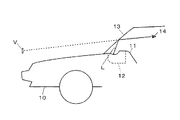
ヘッドアップディスプレイ装置は、図1に示すように車両10のインパネ11に配設された表示ユニットである表示装置12が投射する表示光Lを投影部材である車両10のフロントガラス13で車両10の運転者(観察者)14の方向に反射させ、虚像Vの表示を行うものである。換言すれば、ヘッドアップディスプレイ装置は、表示装置12の後述する表示器から発せられる表示光Lをフロントガラス13(前記投影部材)に照射(投射)し、この照射によって得られた表示像(虚像)Vを運転者14に視認させるものである。これにより運転者14は、虚像Vを風景と重畳させて観察することができる。
As shown in FIG. 1, the head-up display device is configured such that the display light L projected by the
表示装置12は、図2に示すようにバックライトユニット20と、表示器30と、第1反射器40と、第2反射器50と、ハウジング60とから主に構成されている。
As shown in FIG. 2, the
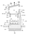
バックライトユニット20 は、図3に示すようにアルミ基板からなる光源基板21上に間隔を空けて複数個配置された発光ダイオードからなる光源22と、この光源22から発せられる熱を放散させるように光源基板21の背面に密着(当接)している放熱部材23と、光源22からの照明光を入射して表示器30に向けて出射するレンズ部材24と、光源22及びレンズ部材24を収納する光源ケース25とを備え、この光源ケース25は、例えば光反射性の良好な乳白色の合成樹脂から形成されている。
As shown in FIG. 3, the
また、放熱部材23は、アルミ等の熱伝導率の高い金属材料にて形成されたヒートシンクからなり、光源基板21を載置するための第1の載置部26と、後述する支持体を載置するための第2の載置部(載置部)27と、ハウジング60外の空気と接触可能な多数の放熱フィン28とを備え、この場合、第2の載置部27は、表示器30側に向けて略L字状に延在する壁部として形成されている。なお、放熱部材23は、適宜固定手段を用いてハウジング60に固定されている。
The
表示器30は、バックライトユニット20の前方側に配置され、バックライトユニット20からの照明光(つまりレンズ部材24から出射される照明光)を透過して表示光Lを形成する(発する)TFT型の液晶表示素子(表示素子)31と、この液晶表示素子31と離間するように液晶表示素子31の前方側(真上)に傾斜配置される透過反射部材としてのホットミラー32と、液晶表示素子31及びホットミラー32を配設(収納もしくは保持)するケース部材33と、液晶表示素子31の背面側周縁部に位置する支持体34とを備えている。なお、必要に応じてバックライトユニット20からの照明光を均一化させるための光拡散板(図示せず)を液晶表示素子31と支持体34との間に配置してもよい。
The
液晶表示素子31は、バックライトユニット20から発せられる照明光により、所定情報を発光表示するものである。つまり、液晶表示素子31は、その背後側に位置する光源基板21上に配置(実装)される光源22からの照明光によって表示光Lを発するようになっている。なお、前記所定情報としては、例えば車速、エンジン回転数、燃費、時刻、ナビゲーション等がある。
The liquid
ホットミラー32は、略矩形状のアクリル樹脂からなる光透過性のガラス基板(基板)32aと、ガラス基板32aの一方の面(つまり図3中、ガラス基板32aの前面)に設けられる多層の干渉膜からなる反射層32bとを備え、ケース部材33の後述する前面開口部を塞ぐように配設される。
The
また、ホットミラー32は、液晶表示素子31から第1反射器40の後述するコールドミラーへと至る表示光Lの光路中に配設され、本例では、反射層32bが、前記コールドミラーに備えられる後述する第1の反射膜と向かい合うような位置関係となっている。
The
なお、ホットミラー32は、液晶表示素子31が発する可視光線からなる表示光Lを効率よく前記コールドミラー側へと透過させるとともに、ハウジング60に配設される後述する透光性カバー、第2反射器50の後述する凹面鏡並びに前記コールドミラーを通じてハウジング60内部となる表示器30に照射する太陽光のうち赤外線(熱線)を吸収(反射)する特性を有している。
The
ケース部材33は、合成樹脂材料もしくは金属材料からなり、傾斜するように配置されているホットミラー32の背面側周縁部を保持する略枠形状からなる基部35と、液晶表示素子31の前面側周縁部を覆うフランジ形状からなる覆い部36と、支持体34を包囲するように覆い部36の背後に垂下形成される垂下部37とが一体形成された構成となっている。
The
基部35は、その上下が貫通している枠形状となっており、液晶表示素子31とホットミラー32との間に位置し、液晶表示素子31から発せられる表示光Lをホットミラー32へと導くための開口孔部35aを有している。
The
また、図3中、右側に位置する基部35箇所の上方側には、太陽光(外光)の一部が前記透光性カバー、前記凹面鏡並びに前記コールドミラーを経てホットミラー32へと照射されることに伴い液晶表示素子31とホットミラー32との間にこもる(滞留する)熱をケース部材33の外部へと放出するための熱放出部である貫通孔形状の第1の貫通部35bが形成されている。
Further, in FIG. 3, a part of sunlight (external light) is irradiated on the
さらに、図3中、左側に位置する基部35箇所の略中央部には、ケース部材33の周囲に存在する外気を導入するための外気導入部である第2の貫通部35cが形成されている。なお、本例の場合、熱放出部35bや外気導入部35cの形状はともに貫通孔形状となっているが、熱放出部35bや外気導入部35cの形状はあらゆる形状を適用することができ、例えば切り欠き形状からなる切り欠き部として形成してもよい。
Further, in FIG. 3, a second through
そして、この場合、ホットミラー32は、開口孔部35aの前面側に位置している前面開口部35dを塞ぐように基部35上に載置され、液晶表示素子31から発せられる表示光Lは、開口孔部35a、ホットミラー32を通過して第1反射器40側に導かれる。
In this case, the
支持体34は、導電性材料(金属材料)からなり、略枠状に形成され、液晶表示素子31を支持する支持部材としての機能を有し、バックライトユニット20から発せられる照明光を液晶表示素子31へと導くための開口孔34aを有している。
The
以上のように構成された表示器30において、太陽光の一部が前記透光性カバー、前記凹面鏡並びに前記コールドミラーを経てホットミラー32へと照射されることに伴い液晶表示素子31とホットミラー32との間に形成される空間領域Sにこもる(滞留する)熱は、第1の貫通部35bを通じてケース部材33外部へと積極的に放出される。
In the
そして、このように空間領域Sに滞留する熱が第1の貫通部35bを通じてケース部材33外部へと放出されると、空間領域Sが負圧の状態となり、ケース部材33の周囲に存在している外気が外気導入部として機能する第2の貫通部35cを通じて空間領域Sへと導入される。
When the heat staying in the space region S is released to the outside of the
従って、表示装置12がインパネ11内部に取り付けられた状態において、ホットミラー32への外光照射に起因して空間領域Sに滞留する熱が、空間領域Sから熱放出部である第1の貫通部35bを通ってケース部材33外部へと放出されるとともに、外気が外気導入部である第2の貫通部35cを通ってケース部材33外部から空間領域Sへと導入されるという、空間領域Sでの空気循環に伴い、空間領域S(つまり液晶表示素子31)が高温状態となるのが抑制される。これにより空間領域Sの背後にある液晶表示素子31の温度上昇が抑制され、液晶表示素子31が誤動作する虞のないヘッドアップディスプレイ装置を提供することができる。
Therefore, in the state where the
なお、本例では、支持体34は、その底面の所要部が放熱部材23に備えられる第2の載置部27上に載置される。よって、液晶表示素子31は、支持体34を介して放熱部材23上に保持されていることから、空間領域Sに滞留する熱は、上述した空間領域Sでの前記空気循環だけではなく、導電性材料からなる支持体34、放熱部材23を経てハウジング60の外部へと放散され、これにより液晶表示素子31の温度上昇をより確実に防止することができる。
In this example, the
なお、以上の説明では、図3中、右側に位置する基部35の上方側に熱放出部である第1の貫通部35bを設け、図3中、左方に位置する基部35の中央部に外気導入部である第2の貫通部35cを設けた例について説明したが、例えば第2の貫通部35cを廃止して、第1の貫通部35bが熱放出部としての機能と外気導入部としての機能とを兼ね備えるような構成としてもよい。
In the above description, the first through
第1反射器40は、ホットミラー32の上方(真上)に位置してなるコールドミラー(第1反射部材)41と、このコールドミラー41を所定の取付手段を用いて取付固定するための取付部材42とを有している。
The
コールドミラー41は、略矩形状のガラス基板41aと、このガラス基板41aの片面(第2反射器50の後述する凹面鏡と向かい合う面)に形成された第1の反射層41bとからなり、かかる第1の反射層41bは、膜厚が異なる多層の干渉膜からなるものであり、蒸着等の方法で形成されている。
The
また、コールドミラー41は、液晶表示素子31から発せられ、ホットミラー32を透過してなる表示光Lを、第2反射器50(前記凹面鏡)側へ反射させるような位置に傾斜状態にて配設される。なお、取付部材42は、例えば黒色の合成樹脂材料からなり、ハウジング60に適宜固定手段を用いて固定されている。
The
第2反射器50は、コールドミラー41(つまり液晶表示素子31)からの表示光Lを反射させる凹面鏡(第2反射部材)51と、この凹面鏡51を保持するミラーホルダ52とを備えている。なお、本実施形態の場合、コールドミラー41と凹面鏡51とが、後述する特許請求の範囲(請求項1)における反射部材に相当する。
The
凹面鏡51は、凹面を有するポリカーボネートからなる樹脂基板に第2の反射層51aを蒸着形成してなるものである。かかる凹面鏡51は、その第2の反射層51aがコールドミラー41並びにハウジング60の後述する透光性カバーに対向し、前記透光性カバーから臨める位置に傾斜状態にて配設される。
The
また、凹面鏡51は、コールドミラー41からの表示光Lを拡大しつつ、前記透光性カバー(車両10のフロントガラス13)側へ反射(投射)させるものである。このことは、凹面鏡51が、コールドミラー41によって反射された表示光Lを拡大し、この拡大された表示光Lを前記透光性カバーを通じてフロントガラス13に投射することを意味している。なお、凹面鏡51は、ミラーホルダ52に両面粘着テープにより接着されている。ミラーホルダ52は、合成樹脂材料からなるものであり、適宜固定手段を用いてハウジング60に固定されている。
The
ハウジング60は、例えば黒色の合成樹脂材料もしくはアルミダイキャストにて形成されてなり、ともに断面略凹部形状からなる上側ケース体61と下側ケース体62とを備え、上側ケース体61と下側ケース体62とで形成される内部空間である空間部63において、バックライトユニット20や表示器30、コールドミラー41を含む第1反射器40、凹面鏡51を含む第2反射器50等を収納(収容)している。
The
上側ケース体61には、凹面鏡51の配設位置の上部(車両10のフロントガラス13側)が開口する開口窓部64が形成されており、凹面鏡51によって反射された表示光Lは、開口窓部64を通過することになる。
The
またハウジング60には、透光部である透光性カバー65が開口窓部64を塞ぐように配設されてなる。かかる透光性カバー65は、透光性の合成樹脂材料(例えばアクリル樹脂)からなり、凹面鏡51で反射された表示光Lが透過(通過)する光透過性部材としての機能を有している。
The
つまり、コールドミラー41並びに凹面鏡51によって反射された表示光Lは、ハウジング60に設けられた透光性カバー65を通じてフロントガラス13に投影され、これにより虚像Vの表示が運転者14に対し行われることになる。なお、66は下側ケース体62の底部に形成された孔部であり、この孔部66には孔部66を塞ぐように放熱部材23が配設される。
In other words, the display light L reflected by the
以上のように本実施形態では、表示光Lを発する表示器30と、表示光Lを反射させるコールドミラー41と凹面鏡51とでなる前記反射部材と、表示器30並びに前記反射部材を収容するハウジング60とを備え、表示器30として、表示光Lを発する液晶表示素子31と、この液晶表示素子31と離間するように液晶表示素子31の前方側に配置されるホットミラー32と、液晶表示素子31及びホットミラー32を配設するケース部材33とが設けられ、前記反射部材によって反射された表示光Lを透光性カバー65を通じてフロントガラス13に投影して観察者14に対し表示を行うヘッドアップディスプレイ装置において、ケース部材33は、液晶表示素子31とホットミラー32との間に位置する基部35を備えるとともに、基部35には、外光の一部が透光性カバー65並びに前記反射部材を経てホットミラー32へと照射されることに伴い液晶表示素子31とホットミラー32との間に滞留する熱をケース部材33の外部へと放出するための熱放出部である第1の貫通部35bが形成されているものである。
As described above, in this embodiment, the
従って、ホットミラー32への外光照射に伴い、ホットミラー32と液晶表示素子31との間に形成される空間領域Sに滞留する熱は、熱放出部である第1の貫通部35bを通じて空間領域Sからケース部材33の外部へと放出されるため、空間領域S内が高温状態となるのが抑制され、空間領域Sの背後にある液晶表示素子31が誤動作する虞のないヘッドアップディスプレイ装置を提供することができる。
Therefore, the heat staying in the space region S formed between the
また本実施形態では、液晶表示素子31は、その背後に位置する光源基板21上に配置される光源22からの照明光によって表示光Lを発し、光源22から発せられる熱は、光源基板21を載置する第1の載置部26を備えた放熱部材23によって放散され、放熱部材23は、液晶表示素子31を支持する導電性材料からなる支持体34を載置するための載置部としての第2の載置部27を備えていることにより、空間領域Sに滞留する熱は、空間領域Sでの前記空気循環だけではなく、導電性材料からなる支持体34、放熱部材23を経てハウジング60の外部へと放散されるため、液晶表示素子31の温度上昇をより確実に防止することができる。
Further, in the present embodiment, the liquid
また本実施形態では、液晶表示素子31と第1反射器40との間にホットミラー32が配置されている例について説明したが、例えばホットミラー32に代えて液晶表示素子31と第1反射器40との間に(換言すれば前面開口部35dを塞ぐように)入射する光の直交する偏光成分の位相を略λ/4ずらす位相差板(λ/4板)を配置したり、あるいはホットミラー32に代えて液晶表示素子31と第1反射器40との間に(換言すれば前面開口部35dを塞ぐように)液晶表示素子31からの表示光を効率よく透過するとともに外光を吸収する偏光板を配置した場合であっても、本実施形態と同様の作用効果が得られる。なお、上述の位相差板や偏光板は特許請求の範囲における請求項2の偏光部材に相当する。
In this embodiment, the example in which the
さらに、図3において、ホットミラー32の背面に前記位相差板または前記偏光板を配置してもよいし、ホットミラー32を廃止して前面開口部35dを塞ぐように前記偏光板を配置するとともに当該偏光板と第1反射器40との間に前記位相差板を配置してもよい。また、図3において、ホットミラー32の背面に前記位相差板を配置するとともに当該位相差板の背面に前記偏光板を配置してもよい。
Further, in FIG. 3, the retardation plate or the polarizing plate may be disposed on the back surface of the
また本実施形態では、ホットミラー32と液晶表示素子31とが非平行状態をなすようにホットミラー32がハウジング60内にて傾斜配置されている例について説明したが、例えばホットミラー32と液晶表示素子31とが平行状態をなすようにホットミラー32と液晶表示素子31との双方をハウジング60内に傾斜配置するような構成としてもよいし、あるいはホットミラー32と液晶表示素子31とが非平行状態をなすようにホットミラー32と液晶表示素子31との双方をハウジング60内に傾斜配置するような構成としてもよい
In this embodiment, the example in which the
なお本実施形態では、液晶表示素子31から発せられる表示光Lが、フロントガラス13に投射される例について説明したが、例えばフロントガラス13に表示光Lを良好に運転者14方向に反射させるコンバイナフィルムを設けてもよいし、あるいはフロントガラス13とは別の専用の反射体に表示光Lを投射する構成としてもよい。
In the present embodiment, the example in which the display light L emitted from the liquid
12 表示装置
13 フロントガラス(投影部材)
14 運転者(観察者)
20 バックライトユニット
21 光源基板
22 光源
23 放熱部材
26 第1の載置部
27 第2の載置部(載置部)
30 表示器
31 液晶表示素子(表示素子)
32 ホットミラー
32a ガラス基板(基板)
32b 反射層
33 ケース部材
34 支持体
35 基部
35a 開口孔部
35b 第1の貫通部(熱放出部)
35c 第2の貫通部(外気導入部)
35d 前面開口部
36 覆い部
37 垂下部
40 第1反射器
41 コールドミラー(第1反射部材)
50 第2反射器
51 凹面鏡(第2反射部材)
60 ハウジング
65 透光性カバー(透光部)
L 表示光
S 空間領域
V 虚像(表示像)
12
14 Driver (observer)
DESCRIPTION OF
30
32
32b
35c 2nd penetration part (outside air introduction part)
35d Front opening 36
50
60
L display light S space area V virtual image (display image)
Claims (3)
前記表示器として、前記表示光を発する表示素子と、前記表示素子と離間するように前記表示素子の前方側に配置されるホットミラーと、前記表示素子及び前記ホットミラーを配設するケース部材とが設けられ、
前記反射部材によって反射された前記表示光を前記ハウジングに形成された透光部を通じて投影部材に投影して観察者に対し表示を行うヘッドアップディスプレイ装置において、
前記ケース部材は、前記表示素子と前記ホットミラーとの間に位置する基部を備えるとともに、
前記基部には、外光の一部が前記透光部並びに前記反射部材を経て前記ホットミラーへと照射されることに伴い前記表示素子と前記ホットミラーとの間に滞留する熱を前記ケース部材の外部へと放出するための熱放出部が形成されていることを特徴とするヘッドアップディスプレイ装置。 A display that emits display light; a reflection member that reflects the display light; and a housing that houses the display and the reflection member.
A display element that emits the display light; a hot mirror that is disposed on the front side of the display element so as to be separated from the display element; and a case member that includes the display element and the hot mirror. Is provided,
In a head-up display device that projects the display light reflected by the reflecting member onto a projection member through a light-transmitting part formed in the housing and displays it to an observer.
The case member includes a base portion located between the display element and the hot mirror,
In the base portion, heat that stays between the display element and the hot mirror when a part of external light is irradiated to the hot mirror through the light transmitting portion and the reflecting member is added to the case member. A head-up display device, characterized in that a heat-dissipating part is formed for discharging to the outside.
前記表示器として、前記表示光を発する表示素子と、前記表示素子と離間するように前記表示素子の前方側に配置される偏光部材と、前記表示素子及び前記偏光部材を配設するケース部材とが設けられ、
前記反射部材によって反射された前記表示光を前記ハウジングに形成された透光部を通じて投影部材に投影して観察者に対し表示を行うヘッドアップディスプレイ装置において、
前記ケース部材は、前記表示素子と前記偏光部材との間に位置する基部を備えるとともに、
前記基部には、外光の一部が前記透光部並びに前記反射部材を経て前記偏光部材へと照射されることに伴い前記表示素子と前記偏光部材との間に滞留する熱を前記ケース部材の外部へと放出するための熱放出部が形成されていることを特徴とするヘッドアップディスプレイ装置。 A display that emits display light; a reflection member that reflects the display light; and a housing that houses the display and the reflection member.
As the display, a display element that emits the display light, a polarizing member that is disposed on the front side of the display element so as to be separated from the display element, and a case member that disposes the display element and the polarizing member; Is provided,
In a head-up display device that projects the display light reflected by the reflecting member onto a projection member through a light-transmitting part formed in the housing and displays it to an observer.
The case member includes a base located between the display element and the polarizing member,
In the base portion, heat that stays between the display element and the polarizing member when a part of external light is irradiated to the polarizing member through the light transmitting portion and the reflecting member is stored in the case member. A head-up display device, characterized in that a heat-dissipating part is formed for discharging to the outside.
前記光源から発せられる熱は、前記光源基板を載置する放熱部材によって放散され、
前記放熱部材は、前記表示素子を支持する導電性材料からなる支持体を載置するための載置部を備えていることを特徴とする請求項1または請求項2記載のヘッドアップディスプレイ装置。 The display element emits the display light by illumination light from a light source disposed on a light source substrate located behind the display element,
The heat generated from the light source is dissipated by a heat radiating member on which the light source substrate is placed,
The head-up display device according to claim 1, wherein the heat radiating member includes a mounting portion for mounting a support made of a conductive material that supports the display element.
Priority Applications (1)
| Application Number | Priority Date | Filing Date | Title |
|---|---|---|---|
| JP2012133379A JP2013174855A (en) | 2012-01-24 | 2012-06-13 | Head-up display device |
Applications Claiming Priority (3)
| Application Number | Priority Date | Filing Date | Title |
|---|---|---|---|
| JP2012012123 | 2012-01-24 | ||
| JP2012012123 | 2012-01-24 | ||
| JP2012133379A JP2013174855A (en) | 2012-01-24 | 2012-06-13 | Head-up display device |
Publications (1)
| Publication Number | Publication Date |
|---|---|
| JP2013174855A true JP2013174855A (en) | 2013-09-05 |
Family
ID=49267773
Family Applications (1)
| Application Number | Title | Priority Date | Filing Date |
|---|---|---|---|
| JP2012133379A Pending JP2013174855A (en) | 2012-01-24 | 2012-06-13 | Head-up display device |
Country Status (1)
| Country | Link |
|---|---|
| JP (1) | JP2013174855A (en) |
Cited By (17)
| Publication number | Priority date | Publication date | Assignee | Title |
|---|---|---|---|---|
| JP2014010321A (en) * | 2012-06-29 | 2014-01-20 | Jvc Kenwood Corp | Image display device and image display method |
| KR20150066316A (en) * | 2013-12-06 | 2015-06-16 | 엘지디스플레이 주식회사 | Head up display device |
| WO2015198862A1 (en) * | 2014-06-26 | 2015-12-30 | 日本精機株式会社 | Head-up display device |
| JP2016122059A (en) * | 2014-12-24 | 2016-07-07 | 日本精機株式会社 | Head-up display |
| JP2017009855A (en) * | 2015-06-24 | 2017-01-12 | デクセリアルズ株式会社 | Head-up display device |
| WO2017154372A1 (en) * | 2016-03-08 | 2017-09-14 | パナソニックIpマネジメント株式会社 | Display device |
| WO2017187514A1 (en) * | 2016-04-26 | 2017-11-02 | 日立マクセル株式会社 | Information display device |
| WO2018062302A1 (en) * | 2016-09-29 | 2018-04-05 | 日立マクセル株式会社 | Head-up display device |
| CN109991738A (en) * | 2017-12-29 | 2019-07-09 | 深圳点石创新科技有限公司 | Vehicle-mounted head-up-display system |
| JP2019191384A (en) * | 2018-04-26 | 2019-10-31 | 日本精機株式会社 | Head-up display |
| US10670863B2 (en) | 2015-08-26 | 2020-06-02 | Denso Corporation | Head-up display device with reflective optical system for vehicle |
| JP2020086220A (en) * | 2018-11-28 | 2020-06-04 | 株式会社リコー | Display unit and movable body |
| WO2020166293A1 (en) * | 2019-02-14 | 2020-08-20 | 株式会社デンソー | Virtual-image display device |
| WO2021246201A1 (en) * | 2020-06-05 | 2021-12-09 | 株式会社小糸製作所 | Vehicular display device |
| WO2024025302A1 (en) * | 2022-07-25 | 2024-02-01 | 삼성전자 주식회사 | Wearable electronic device comprising lens barrel |
| DE112021005783T5 (en) | 2020-11-04 | 2024-02-15 | Nippon Seiki Co., Ltd. | Head-up display and manufacturing process for a head-up display |
| US11971545B2 (en) | 2020-06-05 | 2024-04-30 | Koito Manufacturing Co., Ltd. | Vehicular display device |
-
2012
- 2012-06-13 JP JP2012133379A patent/JP2013174855A/en active Pending
Cited By (32)
| Publication number | Priority date | Publication date | Assignee | Title |
|---|---|---|---|---|
| JP2014010321A (en) * | 2012-06-29 | 2014-01-20 | Jvc Kenwood Corp | Image display device and image display method |
| KR20150066316A (en) * | 2013-12-06 | 2015-06-16 | 엘지디스플레이 주식회사 | Head up display device |
| KR102089251B1 (en) * | 2013-12-06 | 2020-03-16 | 엘지디스플레이 주식회사 | Head up display device |
| WO2015198862A1 (en) * | 2014-06-26 | 2015-12-30 | 日本精機株式会社 | Head-up display device |
| JP2016009155A (en) * | 2014-06-26 | 2016-01-18 | 日本精機株式会社 | Head-up display device |
| US10031341B2 (en) | 2014-06-26 | 2018-07-24 | Nippon Seiki Co., Ltd. | Head-up display device |
| JP2016122059A (en) * | 2014-12-24 | 2016-07-07 | 日本精機株式会社 | Head-up display |
| JP2017009855A (en) * | 2015-06-24 | 2017-01-12 | デクセリアルズ株式会社 | Head-up display device |
| US10670863B2 (en) | 2015-08-26 | 2020-06-02 | Denso Corporation | Head-up display device with reflective optical system for vehicle |
| US10473966B2 (en) | 2016-03-08 | 2019-11-12 | Panasonic Intellectual Property Management Co., Ltd. | Display device |
| WO2017154372A1 (en) * | 2016-03-08 | 2017-09-14 | パナソニックIpマネジメント株式会社 | Display device |
| JP2017161661A (en) * | 2016-03-08 | 2017-09-14 | パナソニックIpマネジメント株式会社 | Display |
| WO2017187514A1 (en) * | 2016-04-26 | 2017-11-02 | 日立マクセル株式会社 | Information display device |
| CN109073887B (en) * | 2016-04-26 | 2021-02-19 | 麦克赛尔株式会社 | Information display device |
| US11828938B2 (en) | 2016-04-26 | 2023-11-28 | Maxell, Ltd. | Information display apparatus |
| JPWO2017187514A1 (en) * | 2016-04-26 | 2019-03-07 | マクセル株式会社 | Information display device |
| CN109073887A (en) * | 2016-04-26 | 2018-12-21 | 麦克赛尔株式会社 | Information display device |
| CN112946898B (en) * | 2016-04-26 | 2023-04-28 | 麦克赛尔株式会社 | Automobile |
| US11221480B2 (en) | 2016-04-26 | 2022-01-11 | Maxell, Ltd. | Information display apparatus |
| CN112946898A (en) * | 2016-04-26 | 2021-06-11 | 麦克赛尔株式会社 | Automobile |
| WO2018062302A1 (en) * | 2016-09-29 | 2018-04-05 | 日立マクセル株式会社 | Head-up display device |
| CN109991738A (en) * | 2017-12-29 | 2019-07-09 | 深圳点石创新科技有限公司 | Vehicle-mounted head-up-display system |
| JP7004217B2 (en) | 2018-04-26 | 2022-01-21 | 日本精機株式会社 | Head-up display |
| JP2019191384A (en) * | 2018-04-26 | 2019-10-31 | 日本精機株式会社 | Head-up display |
| JP2020086220A (en) * | 2018-11-28 | 2020-06-04 | 株式会社リコー | Display unit and movable body |
| JP7151423B2 (en) | 2018-11-28 | 2022-10-12 | 株式会社リコー | display and mobile |
| JP2020134588A (en) * | 2019-02-14 | 2020-08-31 | 株式会社デンソー | Virtual image display device |
| WO2020166293A1 (en) * | 2019-02-14 | 2020-08-20 | 株式会社デンソー | Virtual-image display device |
| WO2021246201A1 (en) * | 2020-06-05 | 2021-12-09 | 株式会社小糸製作所 | Vehicular display device |
| US11971545B2 (en) | 2020-06-05 | 2024-04-30 | Koito Manufacturing Co., Ltd. | Vehicular display device |
| DE112021005783T5 (en) | 2020-11-04 | 2024-02-15 | Nippon Seiki Co., Ltd. | Head-up display and manufacturing process for a head-up display |
| WO2024025302A1 (en) * | 2022-07-25 | 2024-02-01 | 삼성전자 주식회사 | Wearable electronic device comprising lens barrel |
Similar Documents
| Publication | Publication Date | Title |
|---|---|---|
| JP2013174855A (en) | Head-up display device | |
| JP6361939B2 (en) | Display device | |
| JP6216307B2 (en) | Head-up display device and backlight device | |
| EP2755074B1 (en) | Display device for vehicle | |
| JP5353203B2 (en) | Head-up display device | |
| JP6248473B2 (en) | Head-up display device | |
| JP2007065011A (en) | Head-up display device | |
| JP2009288484A (en) | Light emitting display | |
| JP2008070504A (en) | Display | |
| JP7331834B2 (en) | head up display | |
| JP6094203B2 (en) | Vehicle display device | |
| JP6098868B2 (en) | Head-up display device | |
| JP2013178308A (en) | Display device | |
| JP2014238477A (en) | Head-up display device | |
| JP2014085657A (en) | Display device | |
| JP2010132207A (en) | Head-up display device | |
| JP7004217B2 (en) | Head-up display | |
| JP4706839B2 (en) | Display device | |
| JP2019166852A (en) | Head-up display | |
| JP2019008090A (en) | Head-up display device | |
| JP2009229531A (en) | Display device and headup display device | |
| JP2005148658A (en) | Display device | |
| JP2011090976A (en) | Lighting device | |
| JP2011088583A (en) | Illumination device | |
| JP2015024666A (en) | Lighting device |