JP2013174247A - Control system, method for providing stability control to centrifugal compressor, and steam compression system - Google Patents
Control system, method for providing stability control to centrifugal compressor, and steam compression system Download PDFInfo
- Publication number
- JP2013174247A JP2013174247A JP2013103965A JP2013103965A JP2013174247A JP 2013174247 A JP2013174247 A JP 2013174247A JP 2013103965 A JP2013103965 A JP 2013103965A JP 2013103965 A JP2013103965 A JP 2013103965A JP 2013174247 A JP2013174247 A JP 2013174247A
- Authority
- JP
- Japan
- Prior art keywords
- surge
- stall
- condition
- response
- compressor
- Prior art date
- Legal status (The legal status is an assumption and is not a legal conclusion. Google has not performed a legal analysis and makes no representation as to the accuracy of the status listed.)
- Granted
Links
- 238000000034 method Methods 0.000 title claims description 27
- 230000006835 compression Effects 0.000 title claims description 24
- 238000007906 compression Methods 0.000 title claims description 24
- 230000004044 response Effects 0.000 claims abstract description 79
- 238000001514 detection method Methods 0.000 claims abstract description 15
- 239000003507 refrigerant Substances 0.000 claims description 39
- 230000008859 change Effects 0.000 claims description 8
- 238000012937 correction Methods 0.000 claims description 7
- 230000008569 process Effects 0.000 claims description 7
- 230000035484 reaction time Effects 0.000 claims description 3
- 238000007599 discharging Methods 0.000 claims description 2
- 238000005119 centrifugation Methods 0.000 claims 1
- 230000007547 defect Effects 0.000 abstract 1
- 239000007789 gas Substances 0.000 description 22
- 239000007788 liquid Substances 0.000 description 16
- 238000010586 diagram Methods 0.000 description 11
- 239000012530 fluid Substances 0.000 description 5
- XLYOFNOQVPJJNP-UHFFFAOYSA-N water Substances O XLYOFNOQVPJJNP-UHFFFAOYSA-N 0.000 description 5
- 230000003044 adaptive effect Effects 0.000 description 4
- 230000007246 mechanism Effects 0.000 description 4
- CURLTUGMZLYLDI-UHFFFAOYSA-N Carbon dioxide Chemical compound O=C=O CURLTUGMZLYLDI-UHFFFAOYSA-N 0.000 description 3
- 238000001816 cooling Methods 0.000 description 3
- 238000013461 design Methods 0.000 description 3
- FAPWRFPIFSIZLT-UHFFFAOYSA-M Sodium chloride Chemical compound [Na+].[Cl-] FAPWRFPIFSIZLT-UHFFFAOYSA-M 0.000 description 2
- 230000008901 benefit Effects 0.000 description 2
- 210000004556 brain Anatomy 0.000 description 2
- 238000004590 computer program Methods 0.000 description 2
- 238000011161 development Methods 0.000 description 2
- 238000004519 manufacturing process Methods 0.000 description 2
- 230000010349 pulsation Effects 0.000 description 2
- 238000012546 transfer Methods 0.000 description 2
- UXVMQQNJUSDDNG-UHFFFAOYSA-L Calcium chloride Chemical compound [Cl-].[Cl-].[Ca+2] UXVMQQNJUSDDNG-UHFFFAOYSA-L 0.000 description 1
- OKTJSMMVPCPJKN-UHFFFAOYSA-N Carbon Chemical compound [C] OKTJSMMVPCPJKN-UHFFFAOYSA-N 0.000 description 1
- VGGSQFUCUMXWEO-UHFFFAOYSA-N Ethene Chemical compound C=C VGGSQFUCUMXWEO-UHFFFAOYSA-N 0.000 description 1
- 239000005977 Ethylene Substances 0.000 description 1
- KRHYYFGTRYWZRS-UHFFFAOYSA-N Fluorane Chemical compound F KRHYYFGTRYWZRS-UHFFFAOYSA-N 0.000 description 1
- 230000002411 adverse Effects 0.000 description 1
- 238000004378 air conditioning Methods 0.000 description 1
- 239000001110 calcium chloride Substances 0.000 description 1
- 229910001628 calcium chloride Inorganic materials 0.000 description 1
- 229910052799 carbon Inorganic materials 0.000 description 1
- 229910002092 carbon dioxide Inorganic materials 0.000 description 1
- 239000001569 carbon dioxide Substances 0.000 description 1
- 238000010438 heat treatment Methods 0.000 description 1
- 229910000040 hydrogen fluoride Inorganic materials 0.000 description 1
- 230000006698 induction Effects 0.000 description 1
- 239000000463 material Substances 0.000 description 1
- 238000005259 measurement Methods 0.000 description 1
- 238000012986 modification Methods 0.000 description 1
- 230000004048 modification Effects 0.000 description 1
- 230000002028 premature Effects 0.000 description 1
- 238000005057 refrigeration Methods 0.000 description 1
- 238000000926 separation method Methods 0.000 description 1
- 239000011780 sodium chloride Substances 0.000 description 1
- 230000001052 transient effect Effects 0.000 description 1
- 230000007704 transition Effects 0.000 description 1
- 230000001960 triggered effect Effects 0.000 description 1
- 238000013022 venting Methods 0.000 description 1
Images


Classifications
-
- F—MECHANICAL ENGINEERING; LIGHTING; HEATING; WEAPONS; BLASTING
- F04—POSITIVE - DISPLACEMENT MACHINES FOR LIQUIDS; PUMPS FOR LIQUIDS OR ELASTIC FLUIDS
- F04D—NON-POSITIVE-DISPLACEMENT PUMPS
- F04D27/00—Control, e.g. regulation, of pumps, pumping installations or pumping systems specially adapted for elastic fluids
- F04D27/02—Surge control
- F04D27/0207—Surge control by bleeding, bypassing or recycling fluids
-
- F—MECHANICAL ENGINEERING; LIGHTING; HEATING; WEAPONS; BLASTING
- F04—POSITIVE - DISPLACEMENT MACHINES FOR LIQUIDS; PUMPS FOR LIQUIDS OR ELASTIC FLUIDS
- F04D—NON-POSITIVE-DISPLACEMENT PUMPS
- F04D27/00—Control, e.g. regulation, of pumps, pumping installations or pumping systems specially adapted for elastic fluids
- F04D27/02—Surge control
- F04D27/0246—Surge control by varying geometry within the pumps, e.g. by adjusting vanes
-
- F—MECHANICAL ENGINEERING; LIGHTING; HEATING; WEAPONS; BLASTING
- F04—POSITIVE - DISPLACEMENT MACHINES FOR LIQUIDS; PUMPS FOR LIQUIDS OR ELASTIC FLUIDS
- F04D—NON-POSITIVE-DISPLACEMENT PUMPS
- F04D27/00—Control, e.g. regulation, of pumps, pumping installations or pumping systems specially adapted for elastic fluids
- F04D27/02—Surge control
- F04D27/0253—Surge control by throttling
-
- F—MECHANICAL ENGINEERING; LIGHTING; HEATING; WEAPONS; BLASTING
- F04—POSITIVE - DISPLACEMENT MACHINES FOR LIQUIDS; PUMPS FOR LIQUIDS OR ELASTIC FLUIDS
- F04D—NON-POSITIVE-DISPLACEMENT PUMPS
- F04D27/00—Control, e.g. regulation, of pumps, pumping installations or pumping systems specially adapted for elastic fluids
- F04D27/02—Surge control
- F04D27/0284—Conjoint control of two or more different functions
-
- F—MECHANICAL ENGINEERING; LIGHTING; HEATING; WEAPONS; BLASTING
- F04—POSITIVE - DISPLACEMENT MACHINES FOR LIQUIDS; PUMPS FOR LIQUIDS OR ELASTIC FLUIDS
- F04D—NON-POSITIVE-DISPLACEMENT PUMPS
- F04D29/00—Details, component parts, or accessories
- F04D29/40—Casings; Connections of working fluid
- F04D29/42—Casings; Connections of working fluid for radial or helico-centrifugal pumps
- F04D29/44—Fluid-guiding means, e.g. diffusers
- F04D29/46—Fluid-guiding means, e.g. diffusers adjustable
-
- F—MECHANICAL ENGINEERING; LIGHTING; HEATING; WEAPONS; BLASTING
- F25—REFRIGERATION OR COOLING; COMBINED HEATING AND REFRIGERATION SYSTEMS; HEAT PUMP SYSTEMS; MANUFACTURE OR STORAGE OF ICE; LIQUEFACTION SOLIDIFICATION OF GASES
- F25B—REFRIGERATION MACHINES, PLANTS OR SYSTEMS; COMBINED HEATING AND REFRIGERATION SYSTEMS; HEAT PUMP SYSTEMS
- F25B1/00—Compression machines, plants or systems with non-reversible cycle
- F25B1/04—Compression machines, plants or systems with non-reversible cycle with compressor of rotary type
- F25B1/053—Compression machines, plants or systems with non-reversible cycle with compressor of rotary type of turbine type
-
- F—MECHANICAL ENGINEERING; LIGHTING; HEATING; WEAPONS; BLASTING
- F25—REFRIGERATION OR COOLING; COMBINED HEATING AND REFRIGERATION SYSTEMS; HEAT PUMP SYSTEMS; MANUFACTURE OR STORAGE OF ICE; LIQUEFACTION SOLIDIFICATION OF GASES
- F25B—REFRIGERATION MACHINES, PLANTS OR SYSTEMS; COMBINED HEATING AND REFRIGERATION SYSTEMS; HEAT PUMP SYSTEMS
- F25B49/00—Arrangement or mounting of control or safety devices
-
- F—MECHANICAL ENGINEERING; LIGHTING; HEATING; WEAPONS; BLASTING
- F05—INDEXING SCHEMES RELATING TO ENGINES OR PUMPS IN VARIOUS SUBCLASSES OF CLASSES F01-F04
- F05D—INDEXING SCHEME FOR ASPECTS RELATING TO NON-POSITIVE-DISPLACEMENT MACHINES OR ENGINES, GAS-TURBINES OR JET-PROPULSION PLANTS
- F05D2250/00—Geometry
- F05D2250/50—Inlet or outlet
- F05D2250/52—Outlet
-
- F—MECHANICAL ENGINEERING; LIGHTING; HEATING; WEAPONS; BLASTING
- F25—REFRIGERATION OR COOLING; COMBINED HEATING AND REFRIGERATION SYSTEMS; HEAT PUMP SYSTEMS; MANUFACTURE OR STORAGE OF ICE; LIQUEFACTION SOLIDIFICATION OF GASES
- F25B—REFRIGERATION MACHINES, PLANTS OR SYSTEMS; COMBINED HEATING AND REFRIGERATION SYSTEMS; HEAT PUMP SYSTEMS
- F25B2600/00—Control issues
- F25B2600/02—Compressor control
- F25B2600/026—Compressor control by controlling unloaders
- F25B2600/0261—Compressor control by controlling unloaders external to the compressor
Abstract
Description
この出願は、2003年10月10日に出願された「SYSTEM AND METHOD FOR STABILITY CONTROL IN A CENTRIFUGAL COMPRESSOR」という名称の出願番号第10/683,772号の一部係属出願である。 This application is a partially pending application of application number 10 / 683,772 entitled “SYSTEM AND METHOD FOR STABILITY CONTROL IN A CENTRIFUGAL COMPRESSOR” filed on October 10, 2003.
この出願は、一般に制御システムに関する。特に、この出願は、コンプレッサの不安定状況に応答して遠心コンプレッサの可変形状ディフューザー機構を制御するためのシステム及び方法に関する。 This application relates generally to control systems. In particular, this application relates to a system and method for controlling a variable geometry diffuser mechanism of a centrifugal compressor in response to compressor instability.
[0003]遠心コンプレッサは、コンプレッサの作動中にサージ状況(surge conditions)又は失速状況(stall conditions)のような不安定に遭遇することがある。サージ又はサージングは、遠心コンプレッサが軽負荷及び高圧力比率で作動するときに生じることのある不安定な状況である。サージは、圧力及び流れにおける変動、及び、時には、コンプレッサを通る完全な逆流を伴う遷移現象である。制御しない場合は、サージは、コンプレッサの回転素子及び静止素子の双方において過剰な振動を生じさせることがあり、コンプレッサの恒久的な損傷を招くことがある。サージ状況を修正又は修繕する1つの技術は、コンプレッサの入口での流れを増大させるようにコンプレッサの排気ガスの一部をコンプレッサの入口へ戻すために高温ガスバイパス弁の開放を含むことができる。 [0003] Centrifugal compressors may encounter instabilities such as surge conditions or stall conditions during compressor operation. Surge or surging is an unstable situation that can occur when a centrifugal compressor operates at light loads and high pressure ratios. Surge is a transition phenomenon with fluctuations in pressure and flow, and sometimes complete backflow through the compressor. If not controlled, surges can cause excessive vibration in both the rotating and stationary elements of the compressor and can cause permanent damage to the compressor. One technique for correcting or repairing surge conditions may include opening a hot gas bypass valve to return a portion of the compressor exhaust gas to the compressor inlet to increase the flow at the compressor inlet.
[0004]遠心コンプレッサの回転失速は、コンプレッサの回転するインペラにおいて又はインペラの下流側の静止のディフューザーにおいて生じることがある。両者の場合、回転失速の存在は、コンプレッサ及び/又はシステムの性能に悪影響を及ぼすことがある。羽根無しラジアルディフューザーを備えた混合流れ式の遠心コンプレッサは、その意図する作動範囲の一部の範囲、又は、ある場合は、その全範囲にわたってディフューザーの回転失速を生じさせることがある。典型的には、ディフューザーのデザインがディフューザー通路内での流れの一部の分離を伴わずにすべての流れを収容できないので、ディフューザーの回転失速が生じる。 [0004] Centrifugal compressor rotational stall can occur in the rotating impeller of the compressor or in a stationary diffuser downstream of the impeller. In both cases, the presence of rotational stall can adversely affect the performance of the compressor and / or system. Mixed flow centrifugal compressors with vaneless radial diffusers can cause diffuser rotational stalls over some or all of their intended operating ranges. Typically, diffuser rotation stalls occur because the diffuser design cannot accommodate all the flow without some separation of the flow in the diffuser passage.
ディフューザーの回転失速は、低周波数音響エネルギ又は脈動の発生を招く。脈動は、ガス流れ通路内で大きな振幅を有することがあり、コンプレッサ、その制御子又は、他の関連する部品/システムの早期の故障を招くことがある。遠心コンプレッサ内の失速状況を修正又は修繕する1つの技術は、可変形状ディフューザー内のディフューザー空間の閉鎖を含むことができる。ディフューザー空間の閉鎖は、またサージ状況に抵抗するコンプレッサの能力を向上させることができる。しかし、ディフューザーギャップの過剰な閉鎖は、コンプレッサを通る流量又は容量を減少させることがある。 The rotational stall of the diffuser results in the generation of low frequency acoustic energy or pulsations. Pulsations can have large amplitudes in the gas flow path and can lead to premature failure of the compressor, its controller, or other related components / systems. One technique for correcting or repairing stall conditions in a centrifugal compressor can include closing the diffuser space in a deformable diffuser. Closing the diffuser space can also improve the compressor's ability to resist surge conditions. However, excessive closure of the diffuser gap may reduce the flow rate or volume through the compressor.
[0005]本発明は、冷媒蒸気を圧縮するように構成された遠心コンプレッサを有する液体チラー(chiller;冷却器)システムに関する。遠心コンプレッサは、未圧縮の冷媒蒸気を受け取るコンプレッサ入口と、圧縮された冷媒蒸気を排出するコンプレッサ出口とを有する。内部では、コンプレッサは、ディフューザーを通る圧縮された冷媒蒸気の流れ通路を変更するための調整可能なディフューザーリングを有する。液体チラーシステムは、またコンプレッサの出口及び入口間で接続された随意(optional)の高温ガスバイパス弁を含む。随意の高温ガスバイパス弁は、圧縮された冷媒蒸気の一部がコンプレッサの入口からコンプレッサの出口へ流れるのを許容するように、構成され、コンプレッサを通る最少の冷媒蒸気流量を維持するために使用される。 [0005] The present invention relates to a liquid chiller system having a centrifugal compressor configured to compress refrigerant vapor. Centrifugal compressors have a compressor inlet that receives uncompressed refrigerant vapor and a compressor outlet that discharges compressed refrigerant vapor. Internally, the compressor has an adjustable diffuser ring for changing the flow path of the compressed refrigerant vapor through the diffuser. The liquid chiller system also includes an optional hot gas bypass valve connected between the compressor outlet and inlet. An optional hot gas bypass valve is configured to allow a portion of the compressed refrigerant vapor to flow from the compressor inlet to the compressor outlet and is used to maintain a minimum refrigerant vapor flow through the compressor. Is done.
液体チラーシステムは、更に遠心コンプレッサの安定的な作動を維持するようにディフューザー及び随意の高温ガスバイパス弁を制御するための安定制御システムを含む。安定制御システムは、遠心コンプレッサの失速状況の感知に応答してディフューザーリングを制御するための失速反応状態(stall reacting state)と、遠心コンプレッサのサージ状況の感知に応答してディフューザーリングを制御するためのサージ反応状態(surge reacting state)と、遠心コンプレッサ内での第2のサージ状況の感知に応答して随意の高温ガスバイパス弁を制御するための高温ガスオーバーライド状態(override state)と、ディフューザーリングのための最適の位置を得るようにディフューザーリングを制御するための探索状態(probing state)と、を有する。 The liquid chiller system further includes a stability control system for controlling the diffuser and optional hot gas bypass valve to maintain stable operation of the centrifugal compressor. The stability control system controls the stall reacting state to control the diffuser ring in response to sensing the stall condition of the centrifugal compressor, and controls the diffuser ring in response to sensing the surge condition of the centrifugal compressor. A surge reacting state, a hot gas override state to control an optional hot gas bypass valve in response to sensing a second surge condition in the centrifugal compressor, and a diffuser ring And a probing state for controlling the diffuser ring to obtain an optimum position for.
[0006]本発明は、更にコンプレッサと、閉冷媒回路(closed refrigerant circuit)に接続された凝縮器及び蒸発器を有するチラーシステムに関する。コンプレッサは、チラーシステムから未圧縮の冷媒蒸気を受け取るコンプレッサ入口と、圧縮された冷媒蒸気をチラーシステムへ排出するコンプレッサ出口とを有し、ディフューザーがコンプレッサ出口に隣接して位置する。ディフューザーは、コンプレッサ出口への圧縮された冷媒蒸気の通過を許容するように構成されたディフューザー空間を有し、ディフューザーリングがディフューザー空間を通る圧縮された冷媒蒸気の流れを制御するためにディフューザー空間の寸法を変更するようにディフューザー空間内で調整自在に位置する。チラーシステムは、またコンプレッサの安定的な作動を維持するようにコンプレッサ内の失速状況及びサージ状況の検出に応答してディフューザー空間内のディフューザーリングの位置を制御するための安定制御システムを含む。 [0006] The present invention further relates to a chiller system having a compressor and a condenser and an evaporator connected to a closed refrigerant circuit. The compressor has a compressor inlet that receives uncompressed refrigerant vapor from the chiller system and a compressor outlet that discharges the compressed refrigerant vapor to the chiller system, with the diffuser located adjacent to the compressor outlet. The diffuser has a diffuser space configured to allow the passage of compressed refrigerant vapor to the compressor outlet, and the diffuser ring controls the flow of compressed refrigerant vapor through the diffuser space. Adjustable in the diffuser space to change dimensions. The chiller system also includes a stability control system for controlling the position of the diffuser ring within the diffuser space in response to detection of stall conditions and surge conditions within the compressor to maintain stable operation of the compressor.
[0007]本発明は、また、コンプレッサ入口と、コンプレッサ出口と、調整可能な流れ通路を備えた可変形状ディフューザーと、を有する遠心コンプレッサの安定的な作動を維持するための安定制御システムに関する。安定制御システムは遠心コンプレッサ内での失速状況の感知に応答して可変形状ディフューザーの流れ通路を調整するための失速反応状態と、遠心コンプレッサ内でのサージ状況の感知に応答して可変形状ディフューザーの流れ通路を調整するためのサージ反応状態とを有する。 [0007] The present invention also relates to a stability control system for maintaining stable operation of a centrifugal compressor having a compressor inlet, a compressor outlet, and a variable shape diffuser with adjustable flow passages. The stability control system responds to the sensing of a stall condition in the centrifugal compressor, a stall reaction condition for adjusting the flow path of the variable shape diffuser, and the variable shape diffuser of the variable shape diffuser in response to sensing a surge condition in the centrifugal compressor. And a surge reaction state for adjusting the flow passage.
[0008]本発明は、更に調整可能な流れ通路を備えた可変形状ディフューザーを有する遠心コンプレッサ内で安定制御を提供する方法に関する。この方法は、遠心コンプレッサの作動中に遠心コンプレッサ内のサージ状況を繰り返し感知する工程と、遠心コンプレッサの作動中に遠心コンプレッサ内の失速状況を繰り返し感知する工程と、所定のサージ反応時間期間だけ、遠心コンプレッサ内のサージ状況の検出に応答して可変形状ディフューザーの流れ通路を連続的に閉鎖する工程と、検出された失速状況が修正されるか又はサージ状況が検出されるまで、遠心コンプレッサ内の失速状況の検出に応答して可変形状ディフューザーの流れ通路を連続的に閉鎖する工程と、を含む。 [0008] The present invention further relates to a method for providing stability control in a centrifugal compressor having a deformable diffuser with an adjustable flow passage. The method includes repeatedly sensing a surge situation in the centrifugal compressor during operation of the centrifugal compressor, repeatedly sensing a stall situation in the centrifugal compressor during operation of the centrifugal compressor, and a predetermined surge reaction time period. Continuously closing the flow path of the deformable diffuser in response to detection of a surge condition in the centrifugal compressor, and until the detected stall condition is corrected or a surge condition is detected, Continuously closing the flow path of the deformable diffuser in response to detecting a stall condition.
[0009]本発明は、また、コンプレッサの安定的な作動を維持するための制御システムに関する。制御システムは、コンプレッサ内の失速状況又はサージ状況のうちの1つの検出に応答してコンプレッサのディフューザーの流れ通路を閉鎖するように構成された少なくとも1つの第1の制御状態を含む。制御システムは、また、失速状況又はサージ状況が不存在の決定に応答してコンプレッサのディフューザーの流れ通路を開放するように構成された第2の制御状態を含む。 [0009] The present invention also relates to a control system for maintaining stable operation of the compressor. The control system includes at least one first control state configured to close the flow path of the compressor diffuser in response to detecting one of a stall condition or a surge condition in the compressor. The control system also includes a second control state configured to open the flow path of the compressor diffuser in response to the determination of the absence of a stall or surge condition.
[0010]本発明は、更に遠心コンプレッサ内の安定制御を提供する方法に関する。この方法は、遠心コンプレッサの作動中にサージ状況を繰り返し検出する工程と、遠心コンプレッサの作動中に失速状況を繰り返し検出する工程とを含む。方法は、また遠心コンプレッサ内でのサージ状況又は失速状況の検出に応答して遠心コンプレッサのディフューザーの流れ通路を閉鎖する工程と、失速状況又はサージ状況が不存在の検出に応答して遠心コンプレッサのディフューザーの流れ通路を開放する工程とを含む。 [0010] The present invention further relates to a method for providing stability control in a centrifugal compressor. The method includes repeatedly detecting a surge condition during operation of the centrifugal compressor and repeatedly detecting a stall condition during operation of the centrifugal compressor. The method also includes closing the flow passage of the centrifugal compressor diffuser in response to detecting a surge condition or stall condition in the centrifugal compressor, and detecting the centrifugal compressor in response to detecting the absence of the stall condition or surge condition. Opening the flow passage of the diffuser.
[0011]本発明は、また蒸気圧縮システムに関する。蒸気圧縮システムは、閉ループとなって接続されたコンプレッサ、第1の熱交換器及び第2の熱交換器とを含む。コンプレッサは、未圧縮の蒸気を受け取るための入口と、圧縮された蒸気を排出するための出口とを含み、ディフューザーが出口の近傍に位置する。ディフューザーは、出口への圧縮された蒸気の流れを許容するように構成された通路と、通路を通る圧縮された蒸気の流れを制御するために通路の寸法を変更するように通路内に位置するリングとを有する。蒸気圧縮システムは、また、コンプレッサ内での失速状況及びサージ状況の存在又はコンプレッサ内での失速状況及びサージ状況の不存在のうちの一方に応答して通路内のリングの位置を調整するための制御システムを含む。 [0011] The present invention also relates to a vapor compression system. The vapor compression system includes a compressor, a first heat exchanger, and a second heat exchanger connected in a closed loop. The compressor includes an inlet for receiving uncompressed steam and an outlet for discharging compressed steam, with a diffuser located in the vicinity of the outlet. The diffuser is positioned in the passage to change the size of the passage to control the flow of compressed steam through the passage and the passage configured to allow the flow of compressed steam to the outlet. With a ring. The vapor compression system also adjusts the position of the ring in the passage in response to one of the presence of a stall condition and a surge condition in the compressor or the absence of a stall condition and a surge condition in the compressor. Includes control system.
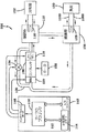
[0019]図1は、加熱、通気及び空調(HVAC)、冷凍又は液体チラーシステムにおいて使用できる例示的な蒸気圧縮システムを概略的に示す。蒸気圧縮システム100は、モータ152により駆動されるコンプレッサ108、凝縮器112、膨張装置(図示せず)及び蒸発器126を通して例えば冷媒である流体を循環させることができる。システム100はまた制御パネル140を含むことができ、制御パネルは、アナログ/デジタル(A/D)コンバータ148と、マイクロプロセッサ150と、不揮発性メモリ144と、インターフェイスボード146とを有することができる。蒸気圧縮システム100内で冷媒として使用できる流体のいくつかの例は、フッ化水素系炭素(HFC)基礎の冷媒(例えばR−410A)、二酸化炭素(CO2;R−744)及び任意の他の形式の冷媒である。
[0019] FIG. 1 schematically illustrates an exemplary vapor compression system that may be used in a heating, venting and air conditioning (HVAC), refrigeration or liquid chiller system. The
[0020]コンプレッサ108と一緒に使用されるモータ152は、可変速度ドライブ(VSD)により稼働することができるか、または、交流(AC)又は直流(DC)電源から直接稼働することができる。使用する場合、可変速度ドライブは、特定の固定のライン電圧及び固定のライン周波数を有するAC電力をAC電源から受け取り、可変の電圧及び周波数を有する電力をモータに供給する。モータ152は、VSDにより稼働できるか、または、AC又はDC電源から直接稼働できる任意の形式の電気モータとすることができる。たとえば、モータ152は、切換え磁気抵抗モータ、誘導モータ、電気的に整流される永久磁石モータ又は任意の他の適当なモータ形式とすることができる。代わりの実施の形態においては、コンプレッサ108を駆動するために、スチーム又はガスタービン又はエンジン及び関連する素子のような他の駆動機構を使用することができる。
[0020] The
[0021]コンプレッサ108は、冷媒蒸気を圧縮し、排出ラインを通して凝縮器112へ圧縮された蒸気を供給する。例示的な実施の形態においては、コンプレッサ108は、遠心コンプレッサとすることができる。コンプレッサ108により凝縮器112へ送給された冷媒蒸気は、例えば水又は空気のような流体へ熱を伝達する。冷媒蒸気は、流体との熱伝達の結果、凝縮器112内で冷媒液体に凝縮する。凝縮器112からの液体冷媒は、膨張装置(図示せず)を通って蒸発器126へ流れる。蒸発器126へ送給された液体冷媒は、例えば空気又は水のような流体から熱を吸収し、冷媒蒸気への位相変化を受ける。蒸気冷媒は、蒸発器126を出て、吸入ラインによりコンプレッサ108へ帰還し、サイクルを完成させる。
[0021] The
[0022]図1に示す例示的な実施の形態においては、凝縮器112内の冷媒蒸気は、水と熱交換関係となり、冷却塔122に接続された熱交換器116を通って流れる。凝縮器112内の冷媒蒸気は、熱交換器コイル内の水との熱交換関係の結果、冷媒液体へと位相変化する。蒸発器126は、冷却負荷130に接続された供給ライン128S及び帰還ライン128Rを有する熱交換器128を含むことができる。熱交換器128は、蒸発器126内で複数のチューブ束を含むことができる。例えば水、エチレン、塩化カルシウムブレイン、塩化ナトリウムブレイン又は、任意の他の適当な補助の液体のような補助の液体は、帰還ライン128Rを介して蒸発器126内へ進行し、供給ライン128Sを介して蒸発器126から出る。蒸発器126内の液体冷媒は、熱交換器128内の補助の液体と熱交換関係となり、熱交換機コイル128内の補助の液体の温度を冷やす。蒸発器126内の冷媒液体は、熱交換器コイル128内の補助の液体との熱交換関係の結果、冷媒蒸気へと位相変化する。
In the exemplary embodiment shown in FIG. 1, the refrigerant vapor in the
[0023]コンプレッサ108への入力即ち入口においては、コンプレッサ108への冷媒の流れを制御するために使用される1又はそれ以上の予備回転ベーン(PRV)又は入口ガイドベーン120が存在する。コンプレッサ108への冷媒の量を増大させ、それによって、システム100の容量を増大させるように、予備回転ベーン120を開くために、アクチュエータが使用される。同様に、アクチュエータは、コンプレッサ108への冷媒の量を減少させ、それによって、システム100の冷却容量を減少させるように、予備回転ベーン120を閉じるために使用される。
[0023] At the input or inlet to the
[0024]図2は、遠心コンプレッサ及びディフューザーの例示的な実施の形態の部分断面図を示す。コンプレッサ108は、冷媒蒸気を圧縮するためのインペラ202を含む。次に、圧縮された蒸気は、ディフューザー119を通過する。ディフューザー119は、可変形状を有する羽根無しラジアルディフューザーとすることができる。可変形状ディフューザー(VGD)119は、ディフューザープレート206と、ノズルベースプレート208との間に形成された、冷媒蒸気の通過のためのディフューザー空間204を有する。ノズルベースプレート208は、ディフューザーリング210と一緒に使用するように構成される。
[0024] FIG. 2 shows a partial cross-sectional view of an exemplary embodiment of a centrifugal compressor and diffuser. The
ディフューザーリング210は、ディフューザー空間即ち通路204を通過する冷媒蒸気の速度を制御するために使用される。ディフューザーリング210は、通路を通って流れる蒸気の速度を増大させるためにディフューザー通路204内へ延びることができ、通路を通って流れる蒸気の速度を減少させるためにディフューザー通路204から引き戻すことができる。ディフューザーリング210は、ディフューザーの可変形状を提供するように電気モータにより駆動される調整機構212を使用して伸縮できる。1つの例示的な可変形状ディフューザーの作動及び素子の一層詳細な説明は、参照としてここに組み込む、2005年3月29日に発行された米国特許第6,872,050号明細書において提供される。
The
[0025]制御パネル140は、システム100の性能を示す入力信号をシステム100から受け取ることのできるA/Dコンバータ148を有する。たとえば、制御パネル140により受け取られる入力信号は、予備回転ベーン120の位置、蒸発器126からの退去冷液体温度、蒸発器126及び凝縮器112の圧力、及び、コンプレッサ排出通路内の聴覚即ち音響圧力測定値を含むことができる。制御パネル140は、またシステム100の作動を制御するためにシステム100の素子へ信号を伝達するためのインターフェイスボード146を有する。たとえば、制御パネル140は、存在する場合の随意の高温ガスバイパス弁134の位置を制御し、また、可変形状ディフューザー119内のディフューザーリング210の位置を制御するように、予備回転ベーン120の位置を制御するために信号を伝達することができる。
The
[0026]制御パネル140は、システム及びコンプレッサの安定性を維持するように、システム100の作動を制御するために、及び、特定のコンプレッサ状況に応答して可変形状ディフューザー119内でのディフューザーリング210の伸長及び引き戻しの時期を決定するために、制御アルゴリズム(algorithm;解法手順)を使用する。制御パネル140は、システム及びコンプレッサの安定性を維持するように、特定のコンプレッサ状況に応答して、存在する場合の随意の高温ガスバイパス弁134(図5乃至7を参照)を開閉するために、制御アルゴリズムを使用することができる。1つの実施の形態においては、制御アルゴリズムは、マイクロプロセッサ150により実行できる一連のインストラクションを有する、不揮発性メモリ144内に記憶されたコンピュータプログラムとすることができる。
[0026] The
1つの例示的な実施の形態においては、制御アルゴリズムは、コンピュータプログラムに埋め込まれ、マイクロプロセッサ150により実行される。しかし、制御アルゴリズムは、デジタル及び/又はアナログハードウエアを使用して履行及び実行することができることを理解すべきである。制御アルゴリズムを実行するためにハードウエアを使用した場合、制御パネル140の対応する形状は、必要な素子を組み込むように、及び、もはや必要となくなることのある任意の素子(例えばA/Dコンバータ148)を除去するように、変更することができる。
In one exemplary embodiment, the control algorithm is embedded in a computer program and executed by the
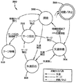
[0027]図3、4、6及び7は、コンプレッサ及びシステムの安定性を維持するための安定制御アルゴリズムの例示的な状態線図を表す。安定制御アルゴリズムは、システムのための他の制御アルゴリズム(例えば差動制御アルゴリズム)に関して別個のプログラムとして実行できるか、または、安定制御アルゴリズムは、システムの他の制御アルゴリズム内に組み込むことができる。図3に示すように、安定制御を図1のシステム100に提供するための安定制御アルゴリズムの例示的な実施の形態の状態線図300は、6つの制御状態を有することができる。制御状態は:始動/休止(シャットダウン)状態302と;失速待機状態304と;失速反応状態306と;探索状態308と;サージ待機状態310と;サージ反応状態312;とを含む。各制御状態は、特定の制御状態のための対応する制御操作を実行するために1又はそれ以上のプログラム又はアルゴリズム又は他の制御装置又は設備を含むことができる。
[0027] FIGS. 3, 4, 6 and 7 represent exemplary state diagrams of stability control algorithms for maintaining compressor and system stability. The stability control algorithm can be run as a separate program with respect to other control algorithms for the system (eg, a differential control algorithm) or the stability control algorithm can be incorporated within other control algorithms of the system. As shown in FIG. 3, a state diagram 300 of an exemplary embodiment of a stable control algorithm for providing stable control to the
[0028]始動/休止状態302は、システム100の作動中の安定制御アルゴリズム300における最初及び最後の制御状態である。不活動状態からシステム100を始動又は開始すると、安定制御アルゴリズム300は、始動/休止状態302に入る。同様に、システム100を失速即ち休止すべき場合、システム100を制御している別の制御アルゴリズム又は、安定制御アルゴリズム300からの休止コマンドに応答して、安定制御アルゴリズム300内の他の制御状態の任意の1つの状態から始動/休止状態302に入る。安定制御アルゴリズム300は、コンプレッサ108が始動するまで、始動/休止状態302に留まる。始動/休止状態302においては、可変形状ディフューザー119のディフューザーリング210は、完全に開いた位置即ち完全に引き戻された位置へ移動し、それによって、ディフューザー空間204を完全に開く。
[0028] Start /
[0029]コンプレッサ108が始動した後に、失速待機状態304に入る。失速反応状態306における失速状況の修正に続いて、失速待機状態304に入ることができる。安定制御アルゴリズム300は、次の状況のうちの1つが生じるまで、失速待機状態304に留まる。このような次の状況とは:所定の失速待機期間が終了した状況;サージ状況が検出された状況;失速状況が検出された状況;または、予備回転ベーン120が所定のPRVオフセット量以上に移動した状況;である。予備回転ベーン120の運動は、コンプレッサの状況(例えば流れ及び/又はヘッド)が変化しており、可変形状ディフューザー119の調整が必要となることがあるというインジケータの表示とすることができる。
[0029] After the
例示的な実施の形態によれば、所定の失速待機期間は、約0.5分から約15分までの範囲とすることができ、約10分とすることができ、所定のPRVオフセット量は、予備回転ベーンの運動範囲の0%から約5%までの範囲とすることができ、約3%とすることができる。失速待機状態304においては、可変形状ディフューザー119のディフューザーリング210は、可変形状ディフューザー119のディフューザーリング210が先の状態内にあって、ディフューザー空間204の開放を保持又は維持しているような位置と同じ位置に保持又は維持される。
According to an exemplary embodiment, the predetermined stall waiting period can range from about 0.5 minutes to about 15 minutes, can be about 10 minutes, and the predetermined PRV offset amount is: The range of motion of the pre-rotating vane can range from 0% to about 5%, and can be about 3%. In the
[0030]失速待機状態304又は、探索状態308のいずれかにおけるコンプレッサ108の失速の検出に応答して、失速反応状態306に入る。コンプレッサの失速を検出するための例示的な技術の工程及び素子の一層詳細な説明は、参照としてここに組み込む、2005年2月22日に発行された米国特許第6,857,845号明細書において提供される。しかし、システムの失速を検出するために、任意の適当な失速検出技術を使用できることを理解すべきである。安定制御アルゴリズム300は、コンプレッサ108内で検出された失速状況が修正又は修繕されるまで、または、サージ状況がコンプレッサ108内で検出されるまで、失速反応状態306に留まる。
[0030] In response to detecting stall of
例示的な実施の形態によれば、失速状況は、対応する失速センサ電圧が所定の失速最小しきい電圧よりも小さくなったという事実に応答して、修正又は修繕されたものとみなされ、その所定の失速最小しきい電圧は、約0.4ボルトから約0.8ボルトの範囲とすることができ、約0.6ボルトとすることができる。失速反応状態306においては、可変形状ディフューザー119のディフューザーリング210は、コンプレッサ108内で検出された失速状況が修正又は修繕されるまで、閉位置の方へ連続的に延びて、ディフューザー空間204の開口を閉じる。失速反応状態306における失速状況が修正又は修繕されたとき、安定制御アルゴリズム300は、失速待機状態304へ戻る。
According to an exemplary embodiment, the stall situation is deemed to have been modified or repaired in response to the fact that the corresponding stall sensor voltage has become less than a predetermined stall minimum threshold voltage, and The predetermined stall minimum threshold voltage can range from about 0.4 volts to about 0.8 volts, and can be about 0.6 volts. In the
[0031]所定の失速待機期間の終了又は失速待機状態304での所定のPRVオフセット量よりも大きな予備回転ベーン120の運動に応答して、探索状態308に入る。サージ待機状態310における所定のサージ待機期間の終了に続いて、探索状態308に入ることができる。安定制御アルゴリズム300は、コンプレッサ108内で失速状況又はサージ状況が検出されるまで、探索状態308に留まる。例示的な実施の形態によれば、失速状況は、対応する失速センサ電圧が所定の失速最大しきい電圧よりも大きくなったという事実に応答して、検出され、その所定の失速最大しきい電圧は、約0.6ボルトから約1.2ボルトの範囲とすることができ、約0.8ボルトとすることができる。探索状態308においては、可変形状ディフューザー119のディフューザーリング210は、サージ状況又は失速状況がコンプレッサ108内で検出されるまで、開くか又は引き戻されて、ディフューザー空間204の開度を増大させる。
[0031] The
例示的な実施の形態によれば、可変形状ディフューザー119のディフューザーリング210は、所定のパルス間隔を有するパルスによりトリガされる増分的な量又は段階ずつ開かれるか又は引き戻され、その所定のパルス間隔は、約0.5秒から約5秒までの範囲とすることができ、約1又は2秒とすることができる。例えばコンプレッサ容量の70%よりも小さいような一層小さなコンプレッサ負荷においては、失速状況は典型的には、サージ状況が生じることのできる前に、検出され、制御される。しかし、コンプレッサ容量の70%よりも大きいような一層大きなコンプレッサ負荷及び極めて高いヘッド又はリフトにおいては、サージ状況は探索状態308にある間に生じることがあり、これは本質的に一時的なもので、失速ノイズとして検出されない。
According to an exemplary embodiment, the
[0032]失速待機状態304、失速反応状態306又は探索状態308のいずれかにおけるコンプレッサ108内でのサージの検出に応答して、サージ反応状態312に入る。コンプレッサ108内でサージを検出する例示的な技術のための工程及び素子の一層詳細な説明は、参照としてここに組み込む、米国特許第6,427,464号明細書において提供される。しかし、任意の適当なサージ検出技術をシステムと一緒に使用できることを理解すべきである。所定のサージ反応時間が終了するまで、安定制御アルゴリズム300は、サージ反応状態312に留まる。
[0032] In response to detecting a surge in the
例示的な実施の形態によれば、所定のサージ反応時間は、約1秒から約30秒までの範囲とすることができ、約5秒とすることができる。サージ反応状態312においては、可変形状ディフューザー119のディフューザーリング210は、所定のサージ反応時間にわたって閉位置の方へ連続的に延びて、ディフューザー空間即ちギャップ204を減少させ、一層安定的なコンプレッサ作動容量を提供する。サージ反応時間期間は、可変形状ディフューザーリング機構212の全体の速度、アクチュエータモータの駆動及びサージ安定性を達成するために必要な所望のVGDリング210の運動応じて、変更することができる。
According to an exemplary embodiment, the predetermined surge response time can range from about 1 second to about 30 seconds, and can be about 5 seconds. In the
[0033]サージ反応状態312においてコンプレッサ108内のサージ状況が修正又は修繕されたとき、サージ待機状態310に入る。安定制御アルゴリズム300は、所定のサージ待機期間が終了するか、または、コンプレッサ108が別のサージ状況に入るまで、サージ待機状態310に留まる。例示的な実施の形態によれば、所定のサージ待機期間は、約0.5分から約15分までの範囲とすることができ、約10分とすることができる。サージ待機状態310においては、可変形状ディフューザー119のディフューザーリング210は、可変形状ディフューザー119のディフューザーリング210が先の状態内にあって、ディフューザー空間204の開放を保持又は維持しているような位置と同じ位置に保持又は維持される。
[0033] When the surge condition in the
例示的な実施の形態においては、安定制御アルゴリズム300は、サージ待機状態310における別のサージ状況の検出に応答してサージ反応状態312へ再度入ることができる。代わりに、サージ待機状態310における別のサージ状況の検出に応答して、別の制御アルゴリズムを使用することができる。サージ事象は、コンプレッサを休止させる時期を決定するために独立的に又は制御アルゴリズムの一部としてカウントすることができる。短時間期間内で継続するサージの場合、安定制御アルゴリズム300又は別の制御アルゴリズムは、コンプレッサ108の損傷を回避するために警報又はコンプレッサ108の休止保護を提供することができる。そのほかは、サージ待機状態310における所定のサージ待機期間の終了に応答して、安定制御アルゴリズム300は探索状態308に入る。
In the exemplary embodiment,
[0034]図4は、図3の状態制御線図と同様の制御システムのための別の例示的な状態線図を示すが、違いは、所定のサージ待機期間が終了するか、または、失速状況が検出されるか、または、コンプレッサ108が別のサージ状況に入るまで、安定制御アルゴリズム300は、サージ待機状態310に留まり、(サージ待機状態310、探索状態308又は失速待機状態304のいずれかから)コンプレッサ108内で検出された失速状況が修正又は修繕されるまで、または、サージ状況がコンプレッサ108内で検出されるまで、安定制御アルゴリズム300は、失速反応状態306に留まることである。サージ待機状態310にある間に失速状況が生じた場合、安定制御アルゴリズム300は、サージ待機状態310におけるサージ待機期間のためのタイマーを中断又は中止させ、失速反応状態306に入る。
[0034] FIG. 4 shows another exemplary state diagram for a control system similar to the state control diagram of FIG. 3, except that a predetermined surge waiting period ends or stalls. Until a condition is detected or the
サージ待機状態310からコンプレッサ108内で検出された失速状況が修正又は修繕されるまで、または、サージ状況がコンプレッサ108内で検出されるまで、安定制御アルゴリズム300は、失速反応状態306に留まる。サージ待機状態310からコンプレッサ108内で検出された失速状況が修正又は修繕されたとき、安定制御アルゴリズム300は、サージ待機状態310へ再度入り、サージ待機状態310におけるサージ待機期間のためのタイマーを再始動させる。別の例示的な実施の形態においては、安定制御アルゴリズム300がサージ待機状態310へ再度入ったとき、サージ待機期間のためのタイマーは、完全な時間期間だけサージ待機状態310に留まるように再始動できる。
The
[0035]図5は、蒸気圧縮システムの別の例示的な実施の形態を概略的に示す。図5に示す蒸気圧縮システム200は、図1に示す蒸気圧縮システム100と同様であるが、違いは、高温ガスバイパスライン132及び高温ガスバイパス(HGBP)弁134がコンプレッサ108の出口即ち排出部と予備回転ベーン120の入口との間で接続されていて、HGBP弁134が開いたときに、サージ状況の存在に応答して、コンプレッサの排出部からの圧縮された冷媒をコンプレッサ108の入口へ送給又は帰還させることができることである。HGBP弁134の位置は、もしあれば圧縮された冷媒の量を規制するように制御され、これはコンプレッサ108に提供される。HGBP弁のための例示的な制御工程の説明は、参照としてここに組み込む、上記米国特許第6,427,464号明細書において提供される。しかし、任意の適当なHGBP弁及び対応する制御プロセスをシステムと一緒に使用できることを理解すべきである。
[0035] FIG. 5 schematically illustrates another exemplary embodiment of a vapor compression system. The
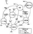
[0036]図6は、図5の蒸気圧縮システムのための制御システムのための例示的な状態線図を示す。図6に示すように、図5のシステムに安定制御を提供する安定制御アルゴリズムの実施の形態のための状態線図500は、図3に示し詳細に上述した安定制御アルゴリズム300のための状態線図と同様であるが、違いは、第7の制御状態である高温ガスオーバーライド状態314及び高温ガスオーバーライド状態314への対応する内部接続部を付加したことである。
[0036] FIG. 6 shows an exemplary state diagram for a control system for the vapor compression system of FIG. As shown in FIG. 6, a state diagram 500 for an embodiment of a stability control algorithm that provides stability control to the system of FIG. 5 is a state line for the
[0037]サージ反応状態312への可能な帰還又は安定制御アルゴリズム300に関して上述したような別のサージ状況の検出に応答しての別の制御アルゴリズムの使用の代わりに、サージ待機状態310の間にコンプレッサ108が第2のサージ状況を体験したことに応答して、高温ガスオーバーライド状態314に入る。安定制御アルゴリズム500は、システムを制御する別の制御アルゴリズムからのHGBP弁開放コマンドの検出に応答して、失速待機状態304、失速反応状態306又は探索状態308から高温ガスオーバーライド状態314へ入ることができる。HGBP弁開放コマンドは、参照としてここに組み込む、上記米国特許第6,427,464号明細書に記載されたように、または、任意の他の適当なHGBP弁を使用して、発生させることができる。
[0037] Instead of using another control algorithm in response to detecting another surge condition as described above with respect to possible feedback to the
安定制御アルゴリズム500は、HGBP弁134が閉位置へ帰還するまで、高温ガスオーバーライド状態314に留まる。高温ガスオーバーライド状態314においては、可変形状ディフューザー119のディフューザーリング210は、HGBP弁134が開位置にあるときにはいつでも適所に保持又は固定され、それによって、システムのヘッドが後に下降し、HGBP弁134が閉じたときに、同様のサージ安定の位置に可変形状ディフューザー119を保つために、ディフューザー空間204の開度を保持又は固定する。高温ガスオーバーライド状態314においてHGBP弁134が閉じたとき、安定制御アルゴリズム500は、失速待機状態304に入る。
The
[0038]図7は、図6と同様の制御システムのための別の例示的な状態線図を示すが、違いは、所定のサージ待機期間が終了するか、失速状況が検出されるか、または、コンプレッサ108が別のサージ状況にはいるまで、安定制御アルゴリズム500がサージ待機状態310に留まり、(サージ待機状態310、探索状態308又は失速待機状態304のいずれかから)コンプレッサ108内で検出された失速状況が修正又は修繕されるまで、または、サージ状況がコンプレッサ108内で検出されるまで、安定制御アルゴリズム500が失速反応状態306に留まることである。サージ待機状態310にある間に失速状況が生じた場合は、安定制御アルゴリズム500は、サージ待機状態310におけるサージ待機期間のためのタイマーを中断又は中止させ、失速反応状態306に入る。
[0038] FIG. 7 shows another exemplary state diagram for a control system similar to FIG. 6, except that a predetermined surge waiting period ends or a stall condition is detected, Or, until the
安定制御アルゴリズム500は、サージ待機状態310からコンプレッサ108内で検出された失速状況が修正又は修繕されるまで、または、サージ状況がコンプレッサ108内で検出されるまで、失速反応状態306に留まる。サージ待機状態310からコンプレッサ108内で検出された失速状況が修正又は修繕されたとき、安定制御アルゴリズム500は、サージ待機状態310に再度入り、サージ待機状態におけるサージ待機期間のためのタイマーを再始動させる。別の例示的な実施の形態においては、安定制御アルゴリズム500がサージ待機状態310に再度入ったとき、サージ待機期間のためのタイマーは、全時間期間に対してサージ待機状態310内に留まるように再始動することができる。
The
[0039]例示的な実施の形態においては、モータ152は、モータ152の速度を変更する可変速度ドライブ(図示せず)に接続される。可変速度ドライブ(VSD)によるコンプレッサの速度の変更は、システムを通る冷媒蒸気の流量及びサージ状況に関するコンプレッサの安定性の双方に影響を及ぼす。安定制御アルゴリズム300、500は、可変速度ドライブに関連して使用することができる。可変速度ドライブを使用した場合、安定制御アルゴリズム300、500がサージ反応状態312にある間にサージが検出されたときに、一層速い速度でコンプレッサを作動させるために、システム作動パラメータ及びコンプレッサPRV位置情報を利用する適応容量制御ロジックを使用することができる。過去の性能パラメータは、適応容量制御ロジックにより未来のサージ状況を回避するためにメモリ内でマップ化又は記憶できる。例示的な適応容量制御工程の説明は、参照としてここに組み込む、米国特許第4,608,833号明細書において提供される。しかし、任意の適当な適応容量制御工程をシステムと一緒に使用できることを理解すべきである。
[0039] In the exemplary embodiment,
[0040]本発明のある特徴及び実施の形態のみを図示し、説明したが、当業者なら、特許請求の範囲に記載した要旨の新規な教示及び利点から本質的に逸脱することなく、多くの修正及び変更(例えば、規模、寸法、構造、形状及び種々の素子の割合の変更、パラメータ(例えば、温度、圧力等)の値、装着構成、材料、色彩、方位の使用等)を行うことができる。任意のプロセス又は方法工程の順番又は順序は、代わりの実施の形態に従って変更又は順番変えできる。 [0040] While only certain features and embodiments of the invention have been illustrated and described, those skilled in the art will recognize many features without departing substantially from the novel teachings and advantages of the claimed subject matter. Modify and change (eg, change in scale, dimensions, structure, shape and proportion of various elements, values of parameters (eg, temperature, pressure, etc.), mounting configuration, material, color, orientation, etc.) it can. The order or sequence of any process or method steps can be changed or re-sequenced according to alternative embodiments.
それ故、特許請求の範囲は、本発明の真の精神内に入るようなすべてのこのような修正及び変更をカバーすることを意図するものであることを理解すべきである。更に、例示的な実施の形態の簡潔な説明を提供する努力として、実際の履行のすべての特徴は述べなかった(即ち、本発明を実行する現時点で考えられる最良のモードに関係しないもの、または、特許請求の範囲の発明を可能にすることに関係しないものは述べなかった)。任意の技術的又は設計的なプロジェクトにおけるような、任意のこのような実際の履行の開発において、多くの履行上の特定の決定を行うことができることを認識すべきである。このような開発努力は、複雑で時間を消費するかもしれないが、それにも拘わらず、過度な経験を伴わずにこの開示の利益を有する当業者にとっては、設計、製作及び製造の日常の仕事であろう。 Therefore, it is to be understood that the claims are intended to cover all such modifications and changes as fall within the true spirit of the invention. Furthermore, in an effort to provide a concise description of exemplary embodiments, not all features of actual implementation have been described (i.e., not related to the best mode currently contemplated for carrying out the invention, or And nothing not related to enabling the claimed invention). It should be appreciated that many implementation specific decisions can be made in the development of any such actual implementation, such as in any technical or design project. Such development efforts may be complex and time consuming, but nonetheless for those skilled in the art who have the benefit of this disclosure without undue experience, the daily work of design, fabrication and manufacture Will.
100、200:蒸気圧縮システム、108:コンプレッサ、112:凝縮器、119:ディフューザー、120:予備回転ベーン、126:蒸発器、134:高温ガスバイパス弁、204:ディフューザー空間、210:ディフューザーリング、300、500:安定制御アルゴリズム、302:始動/休止状態、304:失速待機状態、306:失速反応状態、308:探索状態、310:サージ待機状態、312:サージ反応状態、314:高温ガスオーバーライド状態。 100, 200: Vapor compression system, 108: Compressor, 112: Condenser, 119: Diffuser, 120: Pre-rotation vane, 126: Evaporator, 134: Hot gas bypass valve, 204: Diffuser space, 210: Diffuser ring, 300 500: Stability control algorithm 302: Start / pause state 304: Stall standby state 306: Stall reaction state 308: Search state 310: Surge standby state 312: Surge reaction state 314: Hot gas override state
Claims (17)
コンプレッサ内の失速状況又はサージ状況のうちのいずれか一方の状況の検出に応答して、コンプレッサのディフューザーの流れ通路を閉じるように構成された少なくとも1つの第1の制御状態と、
失速状況又はサージ状況が存在しないとの決定に応答して、コンプレッサのディフューザーの流れ通路を開くように構成された第2の制御状態と、
前記少なくとも1つの第1の制御状態が、前記失速状況の検出に応答して入る失速反応状態と、前記サージ状況の検出に応答して入るサージ反応状態と、
サージ反応状態内で修正されたサージ状況に応答してディフューザーの流れ通路の寸法を維持するように構成されたサージ待機状態と、
前記サージ待機状態における失速状況の発生に応答して失速反応状態に入り、前記失速反応状態における失速状況の修正に応答してサージ待機状態に入ることを特徴とする制御システム。 A control system for maintaining a stable operation of the compressor,
At least one first control state configured to close the flow path of the compressor diffuser in response to detecting either a stall condition or a surge condition in the compressor;
A second control state configured to open the flow path of the compressor diffuser in response to the determination that no stall condition or surge condition exists;
The at least one first control state is a stall reaction state that is entered in response to detection of the stall situation; and a surge reaction state that is entered in response to detection of the surge situation;
A surge standby condition configured to maintain the dimensions of the diffuser flow passage in response to a surge condition corrected within the surge response condition;
A control system, wherein a stall reaction state is entered in response to the occurrence of a stall situation in the surge standby state, and a surge wait state is entered in response to the correction of the stall situation in the stall reaction state.
前記制御システムが、
コンプレッサ内の失速状況又はサージ状況のうちのいずれか一方の状況の検出に応答して、コンプレッサのディフューザーの流れ通路を閉じるように構成された少なくとも1つの第1の制御状態と、
失速状況又はサージ状況が存在しないとの決定に応答して、コンプレッサのディフューザーの流れ通路を開くように構成された第2の制御状態と、
前記少なくとも1つの第1の制御状態が、前記失速状況の検出に応答して入る失速反応状態と、前記サージ状況の検出に応答して入るサージ反応状態と、
サージ反応状態内で修正されたサージ状況に応答してディフューザーの流れ通路の寸法を維持するように構成されたサージ待機状態と、
前記サージ待機状態における失速状況の発生に応答して失速反応状態に入り、前記失速反応状態における失速状況の修正に応答してサージ待機状態に入る、制御システムであり、
前記遠心コンプレッサに安定制御を提供する方法が、
遠心コンプレッサの作動中にサージ状況を繰り返し検出する工程と、
遠心コンプレッサの作動中に失速状況を繰り返し検出する工程と、
遠心コンプレッサにおけるサージ状況又は失速状況の検出に応答して、遠心コンプレッサのディフューザーの流れ通路を閉じる工程と、
失速状況又はサージ状況の不存在の決定に応答して、遠心コンプレッサのディフューザーの流れ通路を開く工程と、を有することを特徴とする、前記方法。 A method for providing stable control to a centrifugal compressor using a control system for maintaining stable operation of the compressor, comprising:
The control system is
At least one first control state configured to close the flow path of the compressor diffuser in response to detecting either a stall condition or a surge condition in the compressor;
A second control state configured to open the flow path of the compressor diffuser in response to the determination that no stall condition or surge condition exists;
The at least one first control state is a stall reaction state that is entered in response to detection of the stall situation; and a surge reaction state that is entered in response to detection of the surge situation;
A surge standby condition configured to maintain the dimensions of the diffuser flow passage in response to a surge condition corrected within the surge response condition;
A control system that enters a stall reaction state in response to the occurrence of a stall situation in the surge standby state, and enters a surge wait state in response to the correction of the stall situation in the stall reaction state;
A method for providing stable control to the centrifugal compressor comprises:
A process of repeatedly detecting surge conditions during operation of the centrifugal compressor;
Repeatedly detecting stall conditions during operation of the centrifugal compressor;
Closing the flow path of the diffuser of the centrifugal compressor in response to detecting a surge condition or stall condition in the centrifugal compressor;
Opening the flow path of the diffuser of the centrifugal compressor in response to determining the absence of a stall condition or a surge condition.
閉ループに接続されたコンプレッサ、第1の熱交換器、及び第2の熱交換器、並びに制御システムを有し、
コンプレッサが、未圧縮の蒸気を受け取るための入口と、圧縮された蒸気を排出するための出口と、出口の近傍に位置するディフューザーと、を有し、
ディフューザーが、出口への圧縮された蒸気の流れを許容するように構成された通路と、通路を通る圧縮された蒸気の流れを制御するために通路の寸法を変更するように通路内に調整自在に位置するリングと、
コンプレッサの安定的な作動を維持するための制御システムとを有し、
前記制御システムが、
コンプレッサ内の失速状況又はサージ状況のうちのいずれか一方の状況の検出に応答して、コンプレッサのディフューザーの流れ通路を閉じるように構成された少なくとも1つの第1の制御状態と、
失速状況又はサージ状況が存在しないとの決定に応答して、コンプレッサのディフューザーの流れ通路を開くように構成された第2の制御状態と、
前記少なくとも1つの第1の制御状態が、前記失速状況の検出に応答して入る失速反応状態と、前記サージ状況の検出に応答して入るサージ反応状態と、
サージ反応状態内で修正されたサージ状況に応答してディフューザーの流れ通路の寸法を維持するように構成されたサージ待機状態と、
前記サージ待機状態における失速状況の発生に応答して失速反応状態に入り、前記失速反応状態における失速状況の修正に応答してサージ待機状態に入る、制御システムであり、
前記制御システムがコンプレッサの失速状況及びサージ状況のうちの1つの存在、又はコンプレッサの失速状況及びサージ状況の不存在に応答して通路内のリングの位置を調整することを特徴とする蒸気圧縮システム。 A vapor compression system,
A compressor connected in a closed loop, a first heat exchanger, and a second heat exchanger, and a control system;
The compressor has an inlet for receiving uncompressed steam, an outlet for discharging the compressed steam, and a diffuser located in the vicinity of the outlet;
A diffuser is adjustable in the passage to change the dimensions of the passage to control the flow of compressed steam through the passage and the passage configured to allow the flow of compressed steam to the outlet A ring located at the
A control system for maintaining a stable operation of the compressor,
The control system is
At least one first control state configured to close the flow path of the compressor diffuser in response to detecting either a stall condition or a surge condition in the compressor;
A second control state configured to open the flow path of the compressor diffuser in response to the determination that no stall condition or surge condition exists;
The at least one first control state is a stall reaction state that is entered in response to detection of the stall situation; and a surge reaction state that is entered in response to detection of the surge situation;
A surge standby condition configured to maintain the dimensions of the diffuser flow passage in response to a surge condition corrected within the surge response condition;
A control system that enters a stall reaction state in response to the occurrence of a stall situation in the surge standby state, and enters a surge wait state in response to the correction of the stall situation in the stall reaction state;
A steam compression system, wherein the control system adjusts the position of the ring in the passage in response to the presence of one of a compressor stall condition and a surge condition, or the absence of a compressor stall condition and a surge condition. .
Applications Claiming Priority (2)
| Application Number | Priority Date | Filing Date | Title |
|---|---|---|---|
| US12/102,459 | 2008-04-14 | ||
| US12/102,459 US7905102B2 (en) | 2003-10-10 | 2008-04-14 | Control system |
Related Parent Applications (1)
| Application Number | Title | Priority Date | Filing Date |
|---|---|---|---|
| JP2011504235A Division JP2011517745A (en) | 2008-04-14 | 2009-04-13 | Control system |
Publications (2)
| Publication Number | Publication Date |
|---|---|
| JP2013174247A true JP2013174247A (en) | 2013-09-05 |
| JP5667239B2 JP5667239B2 (en) | 2015-02-12 |
Family
ID=40758997
Family Applications (2)
| Application Number | Title | Priority Date | Filing Date |
|---|---|---|---|
| JP2011504235A Pending JP2011517745A (en) | 2008-04-14 | 2009-04-13 | Control system |
| JP2013103965A Active JP5667239B2 (en) | 2008-04-14 | 2013-05-16 | Control system, method for providing stable control to a centrifugal compressor, vapor compression system |
Family Applications Before (1)
| Application Number | Title | Priority Date | Filing Date |
|---|---|---|---|
| JP2011504235A Pending JP2011517745A (en) | 2008-04-14 | 2009-04-13 | Control system |
Country Status (6)
| Country | Link |
|---|---|
| US (1) | US7905102B2 (en) |
| JP (2) | JP2011517745A (en) |
| KR (2) | KR101731286B1 (en) |
| CN (1) | CN102007301B (en) |
| TW (1) | TWI468592B (en) |
| WO (1) | WO2009129178A1 (en) |
Cited By (2)
| Publication number | Priority date | Publication date | Assignee | Title |
|---|---|---|---|---|
| JP2014224535A (en) * | 2014-06-20 | 2014-12-04 | 株式会社Ihi | Design method of diffuser ring of turbo compressor |
| JP2016537565A (en) * | 2013-11-18 | 2016-12-01 | グリー エレクトリック アプライアンスイズ インコーポレイテッド オブ チューハイGree Electric Appliances, Inc. Of Zhuhai | Centrifugal compressor and centrifugal water chilling unit |
Families Citing this family (24)
| Publication number | Priority date | Publication date | Assignee | Title |
|---|---|---|---|---|
| CN102575685B (en) * | 2009-10-21 | 2015-08-12 | 开利公司 | For improvement of the centrifugal compressor part load control algorithm of performance |
| GB2468571B (en) * | 2010-03-01 | 2011-01-26 | Flakt Woods Ltd | A method of detecting and controlling stall in an axial fan |
| JP2012052733A (en) * | 2010-09-01 | 2012-03-15 | Mitsubishi Heavy Ind Ltd | Performance evaluation device for turbo freezing machine |
| US9217592B2 (en) * | 2010-11-17 | 2015-12-22 | Johnson Controls Technology Company | Method and apparatus for variable refrigerant chiller operation |
| CN103946555B (en) * | 2011-12-01 | 2016-09-07 | 开利公司 | Surge during the startup of chiller compressor stops |
| US10458690B2 (en) * | 2012-04-30 | 2019-10-29 | Johnson Controls Technology Company | Control system |
| US10371158B2 (en) | 2012-08-17 | 2019-08-06 | Dresser-Rand Company | System and method for detecting stall or surge in radial compressors |
| CN102840182B (en) * | 2012-09-10 | 2016-03-09 | 中国能源建设集团广东省电力设计研究院有限公司 | Thermal power plant's axial-flow blower low-load vibration isolation method and bypass air channel control loop |
| KR20180101630A (en) | 2012-11-09 | 2018-09-12 | 존슨 컨트롤스 테크놀러지 컴퍼니 | Variable geometry diffuser having extended travel and control method thereof |
| CN104421209B (en) * | 2013-08-26 | 2017-02-08 | 珠海格力电器股份有限公司 | Adjuster structure and centrifugal compressor |
| US10330105B2 (en) | 2013-08-27 | 2019-06-25 | Danfoss A/S | Compressor including flow control insert and electromagnetic actuator |
| US20160132027A1 (en) * | 2014-11-11 | 2016-05-12 | Johnson Controls Technology Company | Dither switching extremum seeking control |
| TWI544151B (en) | 2015-11-12 | 2016-08-01 | 財團法人工業技術研究院 | An internal hot gas bypass device coupled with inlet guide vane for centrifugal compressor |
| CN105571181B (en) * | 2016-01-12 | 2017-11-28 | 珠海格力电器股份有限公司 | A kind of variable speed centrifugal chiller plants and its control and regulation method |
| DE102017205500A1 (en) * | 2017-03-31 | 2018-10-04 | BSH Hausgeräte GmbH | Domestic appliance and method for vibration and / or noise reduced operation of a household appliance |
| KR102572313B1 (en) * | 2017-09-25 | 2023-08-29 | 존슨 컨트롤스 테크놀러지 컴퍼니 | Compact variable geometry diffuser mechanism |
| CN109356886A (en) * | 2018-12-17 | 2019-02-19 | 珠海格力电器股份有限公司 | Centrifugal compressor and diffuser system |
| US11143193B2 (en) * | 2019-01-02 | 2021-10-12 | Danfoss A/S | Unloading device for HVAC compressor with mixed and radial compression stages |
| EP3969758A1 (en) * | 2019-05-14 | 2022-03-23 | Carrier Corporation | Method and system for compressor operating range extension via active valve control |
| CN112983846A (en) | 2019-12-02 | 2021-06-18 | 开利公司 | Centrifugal compressor and method for operating a centrifugal compressor |
| US11536277B2 (en) | 2020-04-30 | 2022-12-27 | Trane International Inc. | Interstage capacity control valve with side stream flow distribution and flow regulation for multi-stage centrifugal compressors |
| US11391289B2 (en) | 2020-04-30 | 2022-07-19 | Trane International Inc. | Interstage capacity control valve with side stream flow distribution and flow regulation for multi-stage centrifugal compressors |
| US11841026B2 (en) | 2021-11-03 | 2023-12-12 | Trane International Inc. | Compressor interstage throttle, and method of operating therof |
| CN116771712B (en) * | 2023-08-23 | 2023-10-24 | 中粮生化(成都)有限公司 | Anti-asthma driving system and method for centrifugal compressor |
Citations (1)
| Publication number | Priority date | Publication date | Assignee | Title |
|---|---|---|---|---|
| JP2007509268A (en) * | 2003-10-10 | 2007-04-12 | ヨーク・インターナショナル・コーポレーション | System and method for controlling stability in a centrifugal compressor |
Family Cites Families (38)
| Publication number | Priority date | Publication date | Assignee | Title |
|---|---|---|---|---|
| US3128852A (en) | 1964-04-14 | Prefabricated building wall construction | ||
| US3362624A (en) | 1966-09-06 | 1968-01-09 | Carrier Corp | Centrifugal gas compressor |
| US3392655A (en) | 1967-01-03 | 1968-07-16 | John E. Chambers | Air handling unit for industrial plants |
| US4212585A (en) | 1978-01-20 | 1980-07-15 | Northern Research And Engineering Corporation | Centrifugal compressor |
| US4248055A (en) | 1979-01-15 | 1981-02-03 | Borg-Warner Corporation | Hot gas bypass control for centrifugal liquid chillers |
| US4900232A (en) | 1983-10-07 | 1990-02-13 | The Babcock & Wilcox Company | Compressor surge control method |
| US4503684A (en) | 1983-12-19 | 1985-03-12 | Carrier Corporation | Control apparatus for centrifugal compressor |
| US4697980A (en) | 1984-08-20 | 1987-10-06 | The Babcock & Wilcox Company | Adaptive gain compressor surge control system |
| US4608833A (en) | 1984-12-24 | 1986-09-02 | Borg-Warner Corporation | Self-optimizing, capacity control system for inverter-driven centrifugal compressor based water chillers |
| US4611969A (en) | 1985-08-19 | 1986-09-16 | Carrier Corporation | Calibrating apparatus and method for a movable diffuser wall in a centrifugal compressor |
| US5082421A (en) | 1986-04-28 | 1992-01-21 | Rolls-Royce Plc | Active control of unsteady motion phenomena in turbomachinery |
| US5042245A (en) | 1989-02-27 | 1991-08-27 | United Technologies Corporation | Method and system for controlling variable compressor geometry |
| US5199856A (en) | 1989-03-01 | 1993-04-06 | Massachusetts Institute Of Technology | Passive structural and aerodynamic control of compressor surge |
| US5146764A (en) | 1990-07-25 | 1992-09-15 | York International Corporation | System and method for controlling a variable geometry diffuser to minimize noise |
| US5190440A (en) | 1991-03-11 | 1993-03-02 | Dresser-Rand Company | Swirl control labyrinth seal |
| JPH05157095A (en) | 1991-12-04 | 1993-06-22 | Hitachi Ltd | Capacity controller for centrifugal compressor |
| US5437539A (en) | 1992-07-22 | 1995-08-01 | Massachusetts Institute Of Technology | Apparatus for the dynamic control of rotating stall and surge in turbo machines and the like |
| ES2132243T3 (en) | 1992-08-10 | 1999-08-16 | Dow Deutschland Inc | PROCEDURE AND DEVICE FOR MONITORING AND CONTROLLING A COMPRESSOR. |
| EP0839285B1 (en) | 1994-12-14 | 2001-07-18 | United Technologies Corporation | Compressor stall and surge control using airflow asymmetry measruement |
| US5658125A (en) | 1995-02-28 | 1997-08-19 | Allison Engine Company, Inc. | Magnetic bearings as actuation for active compressor stability control |
| US5730580A (en) | 1995-03-24 | 1998-03-24 | Concepts Eti, Inc. | Turbomachines having rogue vanes |
| CA2184882A1 (en) | 1995-09-08 | 1997-03-09 | Hideomi Harada | Turbomachinery with variable-angle flow guiding vanes |
| WO1997033092A1 (en) | 1996-03-06 | 1997-09-12 | Hitachi, Ltd. | Centrifugal compressor and diffuser for the centrifugal compressor |
| TW402666B (en) | 1997-08-06 | 2000-08-21 | Carrier Corp | Drive positioning mechanism, centrifugal compressor, and backlash adjustment mechanism |
| US6139262A (en) | 1998-05-08 | 2000-10-31 | York International Corporation | Variable geometry diffuser |
| US6036432A (en) | 1998-07-09 | 2000-03-14 | Carrier Corporation | Method and apparatus for protecting centrifugal compressors from rotating stall vibrations |
| US6129511A (en) | 1998-10-27 | 2000-10-10 | Carrier Corporation | Method and apparatus for controlling interaction between variable guide vanes and variable diffuser of a centrifugal compressor |
| US6231301B1 (en) | 1998-12-10 | 2001-05-15 | United Technologies Corporation | Casing treatment for a fluid compressor |
| US6202431B1 (en) | 1999-01-15 | 2001-03-20 | York International Corporation | Adaptive hot gas bypass control for centrifugal chillers |
| FR2804732B1 (en) | 2000-02-03 | 2002-04-12 | Snecma | PROCESS FOR EARLY DETECTION OF AERODYNAMIC INSTABILITY IN A TURBOMACHINE COMPRESSOR |
| US6489085B2 (en) | 2000-12-20 | 2002-12-03 | United Microelectronics Corp. | Thermal reflow photolithographic process |
| KR100390862B1 (en) | 2001-01-17 | 2003-07-10 | 한국과학기술연구원 | Instability detector of turbo compressor |
| US6506010B1 (en) | 2001-04-17 | 2003-01-14 | General Electric Company | Method and apparatus for compressor control and operation in industrial gas turbines using stall precursors |
| US6532433B2 (en) | 2001-04-17 | 2003-03-11 | General Electric Company | Method and apparatus for continuous prediction, monitoring and control of compressor health via detection of precursors to rotating stall and surge |
| AU2003258214A1 (en) | 2002-08-23 | 2004-03-11 | York International Corporation | System and method for detecting rotating stall in a centrifugal compressor |
| US6872050B2 (en) * | 2002-12-06 | 2005-03-29 | York International Corporation | Variable geometry diffuser mechanism |
| EP1781950B1 (en) | 2004-07-13 | 2012-11-14 | Carrier Corporation | Improving centrifugal compressor performance by optimizing diffuser surge control and flow control device settings |
| BRPI0820894A2 (en) | 2007-12-14 | 2015-06-16 | Carrier Corp | Process for controlling operation of a heating, ventilation and air conditioning system and heating, ventilation and air conditioning system |
-
2008
- 2008-04-14 US US12/102,459 patent/US7905102B2/en active Active
-
2009
- 2009-04-13 WO PCT/US2009/040357 patent/WO2009129178A1/en active Application Filing
- 2009-04-13 KR KR1020167015697A patent/KR101731286B1/en active IP Right Grant
- 2009-04-13 JP JP2011504235A patent/JP2011517745A/en active Pending
- 2009-04-13 KR KR1020107025450A patent/KR20110004442A/en active Search and Examination
- 2009-04-13 TW TW98112170A patent/TWI468592B/en active
- 2009-04-13 CN CN200980113040.4A patent/CN102007301B/en active Active
-
2013
- 2013-05-16 JP JP2013103965A patent/JP5667239B2/en active Active
Patent Citations (1)
| Publication number | Priority date | Publication date | Assignee | Title |
|---|---|---|---|---|
| JP2007509268A (en) * | 2003-10-10 | 2007-04-12 | ヨーク・インターナショナル・コーポレーション | System and method for controlling stability in a centrifugal compressor |
Cited By (3)
| Publication number | Priority date | Publication date | Assignee | Title |
|---|---|---|---|---|
| JP2016537565A (en) * | 2013-11-18 | 2016-12-01 | グリー エレクトリック アプライアンスイズ インコーポレイテッド オブ チューハイGree Electric Appliances, Inc. Of Zhuhai | Centrifugal compressor and centrifugal water chilling unit |
| US10302097B2 (en) | 2013-11-18 | 2019-05-28 | Gree Electric Appliances, Inc. Of Zhuhai | Centrifugal compressor and centrifugal water chilling unit |
| JP2014224535A (en) * | 2014-06-20 | 2014-12-04 | 株式会社Ihi | Design method of diffuser ring of turbo compressor |
Also Published As
| Publication number | Publication date |
|---|---|
| US20080253877A1 (en) | 2008-10-16 |
| KR20160075813A (en) | 2016-06-29 |
| WO2009129178A1 (en) | 2009-10-22 |
| JP5667239B2 (en) | 2015-02-12 |
| JP2011517745A (en) | 2011-06-16 |
| TW201000770A (en) | 2010-01-01 |
| CN102007301B (en) | 2015-07-08 |
| KR101731286B1 (en) | 2017-04-28 |
| US7905102B2 (en) | 2011-03-15 |
| KR20110004442A (en) | 2011-01-13 |
| TWI468592B (en) | 2015-01-11 |
| CN102007301A (en) | 2011-04-06 |
Similar Documents
| Publication | Publication Date | Title |
|---|---|---|
| JP5667239B2 (en) | Control system, method for providing stable control to a centrifugal compressor, vapor compression system | |
| JP5209007B2 (en) | System and method for controlling stability in a centrifugal compressor | |
| US8567207B2 (en) | Compressor control system using a variable geometry diffuser | |
| KR101630178B1 (en) | Control system | |
| EP3320213B1 (en) | Capacity control system and method for multi-stage centrifugal compressor | |
| JP2011241760A (en) | Motor-driven compressor, heat source machine, and method of controlling the heat source machine | |
| JP7080801B2 (en) | Centrifugal chiller | |
| JP2023114193A (en) | Control method of refrigerator, control program of refrigerator, and refrigerator | |
| CN117053445A (en) | Anti-surge control method of compressor and air conditioner |
Legal Events
| Date | Code | Title | Description |
|---|---|---|---|
| A621 | Written request for application examination |
Free format text: JAPANESE INTERMEDIATE CODE: A621 Effective date: 20130610 |
|
| A977 | Report on retrieval |
Free format text: JAPANESE INTERMEDIATE CODE: A971007 Effective date: 20140327 |
|
| A131 | Notification of reasons for refusal |
Free format text: JAPANESE INTERMEDIATE CODE: A131 Effective date: 20140401 |
|
| A521 | Request for written amendment filed |
Free format text: JAPANESE INTERMEDIATE CODE: A523 Effective date: 20140626 |
|
| TRDD | Decision of grant or rejection written | ||
| A01 | Written decision to grant a patent or to grant a registration (utility model) |
Free format text: JAPANESE INTERMEDIATE CODE: A01 Effective date: 20141112 |
|
| A61 | First payment of annual fees (during grant procedure) |
Free format text: JAPANESE INTERMEDIATE CODE: A61 Effective date: 20141211 |
|
| R150 | Certificate of patent or registration of utility model |
Ref document number: 5667239 Country of ref document: JP Free format text: JAPANESE INTERMEDIATE CODE: R150 |
|
| R250 | Receipt of annual fees |
Free format text: JAPANESE INTERMEDIATE CODE: R250 |
|
| R250 | Receipt of annual fees |
Free format text: JAPANESE INTERMEDIATE CODE: R250 |
|
| R250 | Receipt of annual fees |
Free format text: JAPANESE INTERMEDIATE CODE: R250 |
|
| R250 | Receipt of annual fees |
Free format text: JAPANESE INTERMEDIATE CODE: R250 |
|
| R250 | Receipt of annual fees |
Free format text: JAPANESE INTERMEDIATE CODE: R250 |
|
| R250 | Receipt of annual fees |
Free format text: JAPANESE INTERMEDIATE CODE: R250 |
|
| R250 | Receipt of annual fees |
Free format text: JAPANESE INTERMEDIATE CODE: R250 |