JP2007509268A - System and method for controlling stability in a centrifugal compressor - Google Patents
System and method for controlling stability in a centrifugal compressor Download PDFInfo
- Publication number
- JP2007509268A JP2007509268A JP2006534385A JP2006534385A JP2007509268A JP 2007509268 A JP2007509268 A JP 2007509268A JP 2006534385 A JP2006534385 A JP 2006534385A JP 2006534385 A JP2006534385 A JP 2006534385A JP 2007509268 A JP2007509268 A JP 2007509268A
- Authority
- JP
- Japan
- Prior art keywords
- diffuser
- surge
- stability control
- compressor
- control system
- Prior art date
- Legal status (The legal status is an assumption and is not a legal conclusion. Google has not performed a legal analysis and makes no representation as to the accuracy of the status listed.)
- Granted
Links
- 238000000034 method Methods 0.000 title claims description 29
- 230000004044 response Effects 0.000 claims abstract description 55
- 238000001514 detection method Methods 0.000 claims abstract description 20
- 239000003507 refrigerant Substances 0.000 claims description 38
- 238000006243 chemical reaction Methods 0.000 claims description 22
- 230000035484 reaction time Effects 0.000 claims description 6
- 230000006835 compression Effects 0.000 claims description 2
- 238000007906 compression Methods 0.000 claims description 2
- 238000007599 discharging Methods 0.000 claims description 2
- 239000007788 liquid Substances 0.000 description 16
- 238000010586 diagram Methods 0.000 description 8
- 238000005057 refrigeration Methods 0.000 description 8
- 230000007246 mechanism Effects 0.000 description 7
- 230000008569 process Effects 0.000 description 7
- XLYOFNOQVPJJNP-UHFFFAOYSA-N water Substances O XLYOFNOQVPJJNP-UHFFFAOYSA-N 0.000 description 5
- 230000003044 adaptive effect Effects 0.000 description 4
- 238000001816 cooling Methods 0.000 description 4
- 238000006073 displacement reaction Methods 0.000 description 3
- FAPWRFPIFSIZLT-UHFFFAOYSA-M Sodium chloride Chemical compound [Na+].[Cl-] FAPWRFPIFSIZLT-UHFFFAOYSA-M 0.000 description 2
- 230000008901 benefit Effects 0.000 description 2
- 239000012267 brine Substances 0.000 description 2
- 238000004590 computer program Methods 0.000 description 2
- 230000010349 pulsation Effects 0.000 description 2
- HPALAKNZSZLMCH-UHFFFAOYSA-M sodium;chloride;hydrate Chemical compound O.[Na+].[Cl-] HPALAKNZSZLMCH-UHFFFAOYSA-M 0.000 description 2
- UXVMQQNJUSDDNG-UHFFFAOYSA-L Calcium chloride Chemical compound [Cl-].[Cl-].[Ca+2] UXVMQQNJUSDDNG-UHFFFAOYSA-L 0.000 description 1
- VGGSQFUCUMXWEO-UHFFFAOYSA-N Ethene Chemical compound C=C VGGSQFUCUMXWEO-UHFFFAOYSA-N 0.000 description 1
- 239000005977 Ethylene Substances 0.000 description 1
- 230000002411 adverse Effects 0.000 description 1
- 239000001110 calcium chloride Substances 0.000 description 1
- 229910001628 calcium chloride Inorganic materials 0.000 description 1
- 230000000694 effects Effects 0.000 description 1
- 239000012530 fluid Substances 0.000 description 1
- -1 for example Substances 0.000 description 1
- 239000000463 material Substances 0.000 description 1
- 238000005259 measurement Methods 0.000 description 1
- 230000002028 premature Effects 0.000 description 1
- 239000000523 sample Substances 0.000 description 1
- 238000000926 separation method Methods 0.000 description 1
- 239000011780 sodium chloride Substances 0.000 description 1
- 239000007858 starting material Substances 0.000 description 1
- 230000007704 transition Effects 0.000 description 1
- 230000001960 triggered effect Effects 0.000 description 1
Images


Classifications
-
- F—MECHANICAL ENGINEERING; LIGHTING; HEATING; WEAPONS; BLASTING
- F04—POSITIVE - DISPLACEMENT MACHINES FOR LIQUIDS; PUMPS FOR LIQUIDS OR ELASTIC FLUIDS
- F04D—NON-POSITIVE-DISPLACEMENT PUMPS
- F04D27/00—Control, e.g. regulation, of pumps, pumping installations or pumping systems specially adapted for elastic fluids
- F04D27/02—Surge control
- F04D27/0284—Conjoint control of two or more different functions
-
- F—MECHANICAL ENGINEERING; LIGHTING; HEATING; WEAPONS; BLASTING
- F04—POSITIVE - DISPLACEMENT MACHINES FOR LIQUIDS; PUMPS FOR LIQUIDS OR ELASTIC FLUIDS
- F04D—NON-POSITIVE-DISPLACEMENT PUMPS
- F04D27/00—Control, e.g. regulation, of pumps, pumping installations or pumping systems specially adapted for elastic fluids
- F04D27/02—Surge control
- F04D27/0207—Surge control by bleeding, bypassing or recycling fluids
-
- F—MECHANICAL ENGINEERING; LIGHTING; HEATING; WEAPONS; BLASTING
- F04—POSITIVE - DISPLACEMENT MACHINES FOR LIQUIDS; PUMPS FOR LIQUIDS OR ELASTIC FLUIDS
- F04D—NON-POSITIVE-DISPLACEMENT PUMPS
- F04D27/00—Control, e.g. regulation, of pumps, pumping installations or pumping systems specially adapted for elastic fluids
- F04D27/02—Surge control
- F04D27/0246—Surge control by varying geometry within the pumps, e.g. by adjusting vanes
-
- F—MECHANICAL ENGINEERING; LIGHTING; HEATING; WEAPONS; BLASTING
- F04—POSITIVE - DISPLACEMENT MACHINES FOR LIQUIDS; PUMPS FOR LIQUIDS OR ELASTIC FLUIDS
- F04D—NON-POSITIVE-DISPLACEMENT PUMPS
- F04D27/00—Control, e.g. regulation, of pumps, pumping installations or pumping systems specially adapted for elastic fluids
- F04D27/02—Surge control
- F04D27/0253—Surge control by throttling
-
- F—MECHANICAL ENGINEERING; LIGHTING; HEATING; WEAPONS; BLASTING
- F04—POSITIVE - DISPLACEMENT MACHINES FOR LIQUIDS; PUMPS FOR LIQUIDS OR ELASTIC FLUIDS
- F04D—NON-POSITIVE-DISPLACEMENT PUMPS
- F04D29/00—Details, component parts, or accessories
- F04D29/40—Casings; Connections of working fluid
- F04D29/42—Casings; Connections of working fluid for radial or helico-centrifugal pumps
- F04D29/44—Fluid-guiding means, e.g. diffusers
- F04D29/46—Fluid-guiding means, e.g. diffusers adjustable
- F04D29/462—Fluid-guiding means, e.g. diffusers adjustable especially adapted for elastic fluid pumps
- F04D29/464—Fluid-guiding means, e.g. diffusers adjustable especially adapted for elastic fluid pumps adjusting flow cross-section, otherwise than by using adjustable stator blades
-
- F—MECHANICAL ENGINEERING; LIGHTING; HEATING; WEAPONS; BLASTING
- F25—REFRIGERATION OR COOLING; COMBINED HEATING AND REFRIGERATION SYSTEMS; HEAT PUMP SYSTEMS; MANUFACTURE OR STORAGE OF ICE; LIQUEFACTION SOLIDIFICATION OF GASES
- F25B—REFRIGERATION MACHINES, PLANTS OR SYSTEMS; COMBINED HEATING AND REFRIGERATION SYSTEMS; HEAT PUMP SYSTEMS
- F25B1/00—Compression machines, plants or systems with non-reversible cycle
- F25B1/04—Compression machines, plants or systems with non-reversible cycle with compressor of rotary type
- F25B1/053—Compression machines, plants or systems with non-reversible cycle with compressor of rotary type of turbine type
-
- F—MECHANICAL ENGINEERING; LIGHTING; HEATING; WEAPONS; BLASTING
- F05—INDEXING SCHEMES RELATING TO ENGINES OR PUMPS IN VARIOUS SUBCLASSES OF CLASSES F01-F04
- F05D—INDEXING SCHEME FOR ASPECTS RELATING TO NON-POSITIVE-DISPLACEMENT MACHINES OR ENGINES, GAS-TURBINES OR JET-PROPULSION PLANTS
- F05D2210/00—Working fluids
- F05D2210/10—Kind or type
- F05D2210/12—Kind or type gaseous, i.e. compressible
-
- F—MECHANICAL ENGINEERING; LIGHTING; HEATING; WEAPONS; BLASTING
- F05—INDEXING SCHEMES RELATING TO ENGINES OR PUMPS IN VARIOUS SUBCLASSES OF CLASSES F01-F04
- F05D—INDEXING SCHEME FOR ASPECTS RELATING TO NON-POSITIVE-DISPLACEMENT MACHINES OR ENGINES, GAS-TURBINES OR JET-PROPULSION PLANTS
- F05D2250/00—Geometry
- F05D2250/50—Inlet or outlet
- F05D2250/52—Outlet
-
- F—MECHANICAL ENGINEERING; LIGHTING; HEATING; WEAPONS; BLASTING
- F25—REFRIGERATION OR COOLING; COMBINED HEATING AND REFRIGERATION SYSTEMS; HEAT PUMP SYSTEMS; MANUFACTURE OR STORAGE OF ICE; LIQUEFACTION SOLIDIFICATION OF GASES
- F25B—REFRIGERATION MACHINES, PLANTS OR SYSTEMS; COMBINED HEATING AND REFRIGERATION SYSTEMS; HEAT PUMP SYSTEMS
- F25B2600/00—Control issues
- F25B2600/02—Compressor control
- F25B2600/026—Compressor control by controlling unloaders
- F25B2600/0261—Compressor control by controlling unloaders external to the compressor
-
- Y—GENERAL TAGGING OF NEW TECHNOLOGICAL DEVELOPMENTS; GENERAL TAGGING OF CROSS-SECTIONAL TECHNOLOGIES SPANNING OVER SEVERAL SECTIONS OF THE IPC; TECHNICAL SUBJECTS COVERED BY FORMER USPC CROSS-REFERENCE ART COLLECTIONS [XRACs] AND DIGESTS
- Y10—TECHNICAL SUBJECTS COVERED BY FORMER USPC
- Y10S—TECHNICAL SUBJECTS COVERED BY FORMER USPC CROSS-REFERENCE ART COLLECTIONS [XRACs] AND DIGESTS
- Y10S415/00—Rotary kinetic fluid motors or pumps
-
- Y—GENERAL TAGGING OF NEW TECHNOLOGICAL DEVELOPMENTS; GENERAL TAGGING OF CROSS-SECTIONAL TECHNOLOGIES SPANNING OVER SEVERAL SECTIONS OF THE IPC; TECHNICAL SUBJECTS COVERED BY FORMER USPC CROSS-REFERENCE ART COLLECTIONS [XRACs] AND DIGESTS
- Y10—TECHNICAL SUBJECTS COVERED BY FORMER USPC
- Y10S—TECHNICAL SUBJECTS COVERED BY FORMER USPC CROSS-REFERENCE ART COLLECTIONS [XRACs] AND DIGESTS
- Y10S417/00—Pumps
Landscapes
- Engineering & Computer Science (AREA)
- Mechanical Engineering (AREA)
- General Engineering & Computer Science (AREA)
- Physics & Mathematics (AREA)
- Geometry (AREA)
- Life Sciences & Earth Sciences (AREA)
- Sustainable Development (AREA)
- Thermal Sciences (AREA)
- Control Of Positive-Displacement Air Blowers (AREA)
- Structures Of Non-Positive Displacement Pumps (AREA)
Abstract
【課題】
【解決手段】遠心圧縮機108に対する安定性制御アルゴリズムが提供される。安定性制御アルゴリズムは、圧縮機の不安定さの検出に応答して可変形態ディフューザ119と、高温ガスのバイパス弁134(設けられているとき)とを制御するため使用される。安定性制御アルゴリズムは、サージ状態又は失速状態の検出に応答して可変形態ディフューザ119内のディフューザリング210の位置を調節することができる。更に、可変形態ディフューザ119内のディフューザリング210は、ディフューザリング210の最適な位置を決定し得るよう調節することができる。連続的なサージ状態の検出に応答して高温ガスのバイパス弁134を開くため安定性制御アルゴリズムを使用することもできる。【Task】
A stability control algorithm for a centrifugal compressor is provided. The stability control algorithm is used to control the variable geometry diffuser 119 and the hot gas bypass valve 134 (when provided) in response to detection of compressor instability. The stability control algorithm can adjust the position of the diffuser ring 210 in the variable geometry diffuser 119 in response to detecting a surge condition or stall condition. Further, the diffuser ring 210 in the variable geometry diffuser 119 can be adjusted to determine the optimal position of the diffuser ring 210. A stability control algorithm can also be used to open the hot gas bypass valve 134 in response to detection of a continuous surge condition.
Description
本発明は、全体として、遠心圧縮機の安定性を制御する制御システム及びその制御方法に関する。より具体的には、本発明は、圧縮機の不安定な状態に応答して遠心圧縮機の可変形態ディフューザ機構を制御するシステム及び方法に関する。 The present invention generally relates to a control system for controlling the stability of a centrifugal compressor and a control method thereof. More specifically, the present invention relates to a system and method for controlling a variable geometry diffuser mechanism of a centrifugal compressor in response to an unstable state of the compressor.
遠心圧縮機は、圧縮機の作動中、サージ又は失速のような不安的状態に遭遇することがある。サージ又はサージングは、遠心圧縮機が軽負荷で、且つ高い圧力比にて作動するときに生じるであろう不安定な状態である。サージは、圧力及び流れが変動する遷移的な現象であり、場合によっては、圧縮機を通って完全に逆方向への流れが生じることがある。サージングは、制御されないならば、圧縮機の回転構成要素及び静止構成要素の双方に過剰な振動を生じさせ、また、圧縮機の恒久的な損傷が生じる結果となる。サージ状態を修正し又は修復する1つの技術は、高温ガスのバイパス弁を開いて、圧縮機の排出ガスの一部を圧縮機の入口に戻して、圧縮機入口における流れを増大させるステップを含むことができる。 Centrifugal compressors may encounter anxious conditions such as surges or stalls during compressor operation. Surge or surging is an unstable condition that may occur when a centrifugal compressor operates at light loads and at high pressure ratios. Surge is a transitional phenomenon in which pressure and flow fluctuate, and in some cases, a completely reverse flow can occur through the compressor. Surging, if not controlled, causes excessive vibration in both the rotating and stationary components of the compressor and results in permanent damage to the compressor. One technique for correcting or repairing a surge condition includes opening a hot gas bypass valve to return a portion of the compressor exhaust gas to the compressor inlet to increase flow at the compressor inlet. be able to.
遠心圧縮機内の回転失速は、圧縮機の回転羽根又は羽根の下流の圧縮機の静止ディフューザ内にて生ずる可能性がある。その双方の場合、回転失速の存在は、圧縮機及び(又は)システムの性能に悪影響を与える可能性がある。羽根無しラジアルディフューザを有する混流遠心圧縮機は、その所期の作動範囲の一部にて、又は、場合によっては、その作動範囲に全部にて、ディフューザの回転失速を経験することがある。典型的に、ディフューザは、流れの一部がディフューザ通路内にて分離を経験せずには、全ての流れを受容することができない設計であるため、ディフューザの回転失速が生じる。ディフューザの回転失速の結果、低周波数の音エネルギすなわち脈動が形成されることになる。これらの脈動は、ガス流路内にて大きい値となり、また、圧縮機、その制御装置又はその他の関係した部品/システムが過早に故障する結果となる。遠心圧縮機の失速状態を修正し又は修復する1つの技術は、可変形態ディフューザ内のディフューザ空間を閉じることを含むことができる。ディフューザ空間を閉じることは、サージ状態に抵抗する圧縮機の能力を向上させることもできる。しかし、ディフューザ空隙の過剰な閉塞は、圧縮機を通る流量又は容量を減少させる可能性がある。 Rotational stall in a centrifugal compressor can occur in the compressor's rotating vanes or in the compressor's stationary diffuser downstream of the vanes. In both cases, the presence of rotational stall can adversely affect compressor and / or system performance. A mixed flow centrifugal compressor having a vaneless radial diffuser may experience a diffuser rotational stall in part of its intended operating range or, in some cases, in its entire operating range. Typically, a diffuser is a design in which a portion of the flow cannot accept all the flow without experiencing separation in the diffuser passage, resulting in diffuser rotational stall. As a result of the rotational stall of the diffuser, low frequency sound energy or pulsation is formed. These pulsations are high in the gas flow path and result in premature failure of the compressor, its controller or other related parts / systems. One technique for correcting or repairing the stall condition of a centrifugal compressor can include closing the diffuser space within the variable geometry diffuser. Closing the diffuser space can also improve the compressor's ability to resist surge conditions. However, excessive blockage of the diffuser gap can reduce the flow rate or volume through the compressor.
このため、失速及び(又は)サージに抵抗し、且つ遠心圧縮機の安定的な作動を実現するため遠心圧縮機内の可変形態ディフューザ(また、存在するならば、選択的な高温ガスバイパス弁)の制御の調和を図るシステム及び方法が必要とされている。 For this reason, a variable form diffuser (and optional hot gas bypass valve, if present) in the centrifugal compressor to resist stall and / or surge and to provide stable operation of the centrifugal compressor. What is needed is a system and method for harmonizing control.
本発明の1つの実施の形態は、冷媒の蒸気を圧縮する形態とされた遠心圧縮機を有する液体冷却機システムに関する。遠心圧縮機は、圧縮されない冷媒蒸気を受ける圧縮機入口と、圧縮した冷媒蒸気を排出する圧縮機出口とを有している。内部にて、圧縮機は、ディフューザを通る圧縮した冷媒蒸気の流路を変化させる可調節型ディフューザリングを有するディフューザを備えている。液体冷却機は、また、圧縮機出口と入口との間に接続される選択的な高温ガスバイパス弁も有している。選択的な高温ガスバイパス弁は、圧縮した冷媒蒸気の一部分が圧縮機出口から圧縮機入口まで流れるのを許容する形態とされており、該バイパス弁は、圧縮機を通る冷媒蒸気の最小の流量を維持するため使用される。液体冷却機システムは、ディフューザ及び選択的な高温ガスバイパス弁を制御し、遠心圧縮機の安定的な作動を維持する安定性制御システムを更に有している。安定性制御システムは、遠心圧縮機内の失速状態の検出に応答してディフューザリングを制御する失速反応状態と、遠心圧縮機内のサージ状態の検出に応答してディフューザリングを制御するサージ反応状態と、遠心圧縮機内の第二のサージ状態の検出に応答して選択的な高温ガスバイパス弁を制御する高温ガスのオーバライド状態と、ディフューザリングに対する最適な位置を得ることができるようディフューザリングを制御する探査状態とを有している。 One embodiment of the present invention relates to a liquid chiller system having a centrifugal compressor configured to compress refrigerant vapor. The centrifugal compressor has a compressor inlet for receiving uncompressed refrigerant vapor and a compressor outlet for discharging the compressed refrigerant vapor. Internally, the compressor includes a diffuser having an adjustable diffuser ring that changes the flow path of the compressed refrigerant vapor through the diffuser. The liquid chiller also has an optional hot gas bypass valve connected between the compressor outlet and inlet. The selective hot gas bypass valve is configured to allow a portion of the compressed refrigerant vapor to flow from the compressor outlet to the compressor inlet, the bypass valve having a minimum flow rate of refrigerant vapor through the compressor. Used to maintain. The liquid chiller system further includes a stability control system that controls the diffuser and optional hot gas bypass valve to maintain stable operation of the centrifugal compressor. The stability control system includes a stall reaction state that controls diffuser ring in response to detection of a stall condition in the centrifugal compressor, a surge reaction state that controls diffuser ring in response to detection of a surge condition in the centrifugal compressor, Exploration to control the diffuser ring to obtain the optimal position for the diffuser ring and the hot gas override condition to control the selective hot gas bypass valve in response to detecting a second surge condition in the centrifugal compressor State.
本発明の別の実施の形態は、閉冷媒回路内に接続された圧縮機と、凝縮器と、蒸発器とを有する冷却機システムに関する。圧縮機は、冷却機システムから圧縮されていない冷媒蒸気を受ける圧縮機入口と、圧縮した冷媒蒸気を冷却機システムまで排出する圧縮機出口と、圧縮機出口に隣接して配置されたディフューザとを有している。ディフューザは、圧縮した冷媒蒸気が圧縮機出口まで流れるのを許容する形態とされたディフューザ空間と、ディフューザ空間の寸法を変化させ、ディフューザ空間を通る圧縮した冷媒蒸気の流れを制御すべくディフューザ空間内に調節可能に配置されたディフューザリングとを有している。冷却機システムは、また、圧縮機内の失速状態及びサージ状態の検出に応答してディフューザ空間内のディフューザリングの位置を制御し、圧縮機の安定的な作動を維持する安定性制御システムも有している。 Another embodiment of the present invention relates to a chiller system having a compressor, a condenser, and an evaporator connected in a closed refrigerant circuit. The compressor includes a compressor inlet that receives uncompressed refrigerant vapor from the chiller system, a compressor outlet that discharges the compressed refrigerant vapor to the chiller system, and a diffuser disposed adjacent to the compressor outlet. Have. The diffuser has a diffuser space configured to allow compressed refrigerant vapor to flow to the compressor outlet, and changes the dimensions of the diffuser space to control the flow of compressed refrigerant vapor through the diffuser space. And a diffuser ring arranged to be adjustable. The chiller system also has a stability control system that controls the position of the diffuser ring in the diffuser space in response to detection of stall and surge conditions in the compressor and maintains stable operation of the compressor. ing.
本発明の更に別の実施の形態は、圧縮機入口と、圧縮機出口と、調節可能な流路を有する可変形態ディフューザとを備える遠心圧縮機の安定的な作動を維持する安定性制御システムに関するものである。安定性制御システムは、遠心圧縮機内の失速状態及びサージ反応状態の検出に応答して可変形態ディフューザの流路を調節し、遠心圧縮機内のサージ状態の検出に応答して可変形態ディフューザの流路を調節する失速反応状態を有している。 Yet another embodiment of the present invention relates to a stability control system for maintaining stable operation of a centrifugal compressor comprising a compressor inlet, a compressor outlet, and a variable geometry diffuser having an adjustable flow path. Is. The stability control system adjusts the flow path of the variable configuration diffuser in response to detection of a stall condition and a surge reaction condition in the centrifugal compressor, and the flow path of the variable configuration diffuser in response to detection of a surge condition in the centrifugal compressor. It has a stall reaction state that regulates.
本発明の更なる実施の形態は、調節可能な流路を有する可変形態ディフューザを備える遠心圧縮機内にて安定性制御を実現する方法に関する。この方法は、遠心圧縮機の作動中、遠心圧縮機内のサージ状態を反復的に検出するステップと、遠心圧縮機の作動中、遠心圧縮機内の失速状態を反復的に検出するステップと、遠心圧縮機内のサージ状態の検出に応答して所定のサージ反応時間、可変形態ディフューザの流路を連続的に閉じるステップと、遠心圧縮機内の失速状態の検出に応答して検出した失速状態が修正され又はサージ状態が検出される迄、可変形態ディフューザの流路を連続的に閉じるステップとを備えている。 A further embodiment of the invention relates to a method for achieving stability control in a centrifugal compressor comprising a variable geometry diffuser with adjustable flow path. The method includes repeatedly detecting a surge condition in the centrifugal compressor during operation of the centrifugal compressor, repeatedly detecting a stall condition in the centrifugal compressor during operation of the centrifugal compressor, and centrifugal compression. A step of continuously closing the flow path of the variable form diffuser with a predetermined surge reaction time in response to detection of a surge condition in the machine, and a stall condition detected in response to detection of a stall condition in the centrifugal compressor is corrected or Continuously closing the flow path of the deformable diffuser until a surge condition is detected.
本発明の1つの有利な効果は、遠心圧縮機をサージ状態及び失速状態の存在の双方に効果的に反応するよう制御することが可能な点である。
本発明の別の有利な効果は、存在するならば、高温ガスバイパス弁の使用が最小限にてより大きいエネルギ効率を提供することである。
One advantageous effect of the present invention is that the centrifugal compressor can be controlled to react effectively to both surge and stall conditions.
Another advantage of the present invention is that the use of a hot gas bypass valve, if present, provides greater energy efficiency with a minimum.
本発明のその他の特徴及び有利な効果は、単に一例として本発明の原理を示す添付図面と共に参照するとき、好ましい実施の形態の以下のより詳細な説明から明らかになるであろう。 Other features and advantages of the present invention will become apparent from the following more detailed description of the preferred embodiment, taken in conjunction with the accompanying drawings which illustrate, by way of example only, the principles of the invention.
可能な場合、図面の全体を通じて同一又は同様の部品を示すために同一の参照番号を使用する。 Wherever possible, the same reference numbers will be used throughout the drawings to refer to the same or like parts.
本発明を適用することのできる全体的なシステムは、単に一例として、図1に示されている。図示するように、冷凍又は液体冷却機システム100であるHVACは、圧縮機108と、凝縮器112と、水冷却機又は蒸発器126と、制御盤140とを有している。制御盤140は、アナログ対デジタル(A/D)変換器148と、マイクロプロセッサ150と、不揮発性記憶装置144と、インターフェース盤146とを有することができる。制御盤140の作用については、以下により詳細に説明する。従来の液体冷却機システム100は、図1に示さないその他の多くの特徴を備えている。これらの特徴は、図示を容易にすべく図面の簡略化のため意図的に省略されている。
The overall system to which the present invention can be applied is shown in FIG. 1 by way of example only. As shown, the HVAC that is the refrigeration or
圧縮機108は、冷媒蒸気を圧縮し、且つ、蒸気を排出管を通して凝縮器112に送り出す。圧縮機108は、遠心圧縮機であることが好ましい。圧縮機108を駆動するため、システム100は、圧縮機108のモータ又は駆動機構152を有している。「モータ」という用語は、圧縮機108の駆動機構に関して使用するが、「モータ」という用語は、モータにのみ限定されず、可変速度駆動装置及びモータ始動器のようなモータ152の駆動に関連して使用することのできる任意の構成要素を包含することを意図するものであることを理解すべきである。本発明の1つの好ましい実施の形態において、モータ又は駆動機構152は、電気モータ及び関係した構成要素である。しかし、蒸気又はガスタービン又はエンジン及び関係した構成要素のようなその他の駆動機構を使用して圧縮機108を駆動することができる。
The
圧縮機108により凝縮器112に送り出された冷媒蒸気は、例えば、空気又は水のような流体との熱交換関係に入り、熱交換関係の結果、冷媒液体へと相変化する。凝縮器112からの凝縮した液体冷媒は、膨張装置(図示せず)を通って蒸発器126に流れる。1つの好ましい実施の形態において、凝縮器112内の冷媒蒸気は、冷却塔122と接続された熱交換コイル116を通って流れる水と熱交換する。凝縮器112内の冷媒蒸気は、熱交換器コイル116内の水と熱交換して冷媒液体に相変化する。
The refrigerant vapor sent to the
蒸発器126は、供給管128Sと、冷却負荷130と接続され戻し管128Rとを有する熱交換器コイル128を備えることが好ましい。熱交換器コイル128は、蒸発器126内に複数の管束を有することができる。水であることが好ましいが、例えば、エチレン、塩化カルシウム塩水又は塩化ナトリウム塩水のような任意の他の適宜な二次的液体とすることのできる第二の液体は、戻し管128Rを介して蒸発器126内に流れ、且つ供給管128Sを介して蒸発器126から出る。蒸発器126内の液体冷媒は、熱交換器コイル128内の第二の液体と熱交換し、熱交換器コイル128内の第二の液体の温度を冷却する。蒸発器126内の冷媒液体は、熱交換器コイル128内の第二の液体と熱交換して冷媒蒸気に相変化する。蒸発器126内の冷媒蒸気は、蒸発器126を出て、且つ吸引管により圧縮機108に戻りサイクルを完了させる。システム100について凝縮器112及び蒸発器126に対する好ましい実施の形態に関して説明したが、凝縮器112及び蒸発器126内での冷媒の適宜な相変化が実現されるならば、凝縮器112及び蒸発器126の任意の適宜な形態がシステム100内にて使用可能であることが理解される。
The
蒸発器126から圧縮機108への供給部又は入口において、圧縮機108への冷媒の流れを制御する1つ又はより多数の予回転ベーン(PRV)又は入口案内ベーン120がある。アクチュエータを使用して予回転ベーン120を開き、圧縮機108への冷媒の量を増し、これによりシステム100の冷却能力を増大させる。同様に、アクチュエータを使用して予回転ベーン120を閉じて圧縮機108への冷媒の量を減少させ、これによりシステム100の冷却能力を低下させる。
There is one or more pre-rotating vanes (PRV) or
図2には、本発明の好ましい実施の形態の圧縮機108の部分断面図が示されている。圧縮機108は、冷媒蒸気を圧縮する羽根202を有している。次に、圧縮された蒸気は、ディフューザ119を通って流れる。ディフューザ119は、可変幾何学的形態を有する羽根無しラジアルディフューザであることが好ましい。可変形態ディフューザ(VGD)119は、冷媒蒸気が通るためディフューザ板206とノズル基部板208との間に形成されたディフューザ空間204を有している。ノズル基部板208は、ディフューザリング210と共に使用する形態とされている。ディフューザリング210を使用してディフューザ空間又は通路202を通って流れる冷媒蒸気の速度を制御する。ディフューザリング210は、ディフューザ通路202内に伸ばされ、該通路を通って流れる蒸気の速度を増し、また、ディフューザ通路202から後退させて該通路を通って流れる蒸気の速度を遅くすることができる。ディフューザリング210は、電気モータにより駆動される調節機構212を使用して伸ばされ且つ後退され、ディフューザ119の可変幾何学的形態を提供することができる。可変形態ディフューザ119の1つの型式の作用及び構成要素に関するより詳細な説明は、その内容を参考として引用し本明細書に含めた、2002年12月6日付けで出願された、米国特許出願明細書10/313,364号に記載されている。しかし、本発明と共に任意の適宜なVGD119が使用可能であることを理解すべきである。
FIG. 2 shows a partial cross-sectional view of the
制御盤140は、システム100の性能を表示するシステム100からの入力信号を受け取ることが好ましいA/D変換器148を有している。例えば、制御盤140により受け取った入力信号は、予回転ベーン120の位置、蒸発器126から去る冷却した液体の温度、蒸発器126及び凝縮器112の圧力、圧縮機の排出通路内の音響学的又は音圧の測定値を含むことができる。制御盤140は、また、信号をシステム100の構成要素に送信しシステム100の作用を制御するインターフェース盤146も有している。例えば、制御盤140は、予回転ベーン120の位置を制御し、存在するならば、選択的な高温ガスバイパス弁134(図4参照)の位置を制御し、また、可変形態ディフューザ119内のディフューザリング210の位置を制御するため信号を送信することができる。制御盤140は、また、図1に示さない多数の特徴及び構成要素を含むことができる。これらの特徴及び構成要素は、図示を容易にすべく制御盤140を簡略化するため、意図的に省略されている。
The
制御盤140は、システム100の作用を制御し且つ特に圧縮機の状態に応答して可変形態ディフューザ119内にてディフューザリング210を伸ばし、或いは後退させるべきときを決定し、システム及び圧縮機の安定性を維持するため制御アルゴリズムを使用する。更に、制御盤140は、特定の圧縮機の状態に応答して、存在するならば、選択的な高温ガスバイパス弁134(図4及び図5参照)を開き或いは閉じてシステム及び圧縮機の安定性を維持するため制御アルゴリズムを使用することができる。1つの実施の形態において、制御アルゴリズムは、マイクロプロセッサ150により実行可能な一連の命令を有する不揮発性記憶装置144内に記憶させたコンピュータプログラムとすることができる。制御アルゴリズムは、コンピュータプログラムにて具体化し、且つマイクロプロセッサ150により実行されることが好ましいが、制御アルゴリズムは、当該技術の当業者によりデジタル及び/又はアナログハードウェアを使用して具体化し、且つ実行することが可能であることを理解すべきである。ハードウェアを使用して制御アルゴリズムを実行するならば、必要な構成要素を内蔵し、また、例えば、A/D変換器148のような、最早、不要である任意の構成要素を省くため、制御盤140の相応する形態を変更することができる。
The
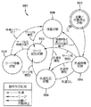
図3及び図5は、圧縮機及びシステムの安定性を維持する本発明の安定性制御アルゴリズムの状態線図である。安定性制御アルゴリズムは、例えば、操作上の制御アルゴリズムのようなシステムに対するその他の制御アルゴリズムに関する別個のプログラムとして実行することが可能であり、或いは安定性制御アルゴリズムは、システムのその他の制御アルゴリズム内に組み込むことができる。図3に示すように、図1のシステム100に対し安定性制御機能を提供する本発明の安定性制御アルゴリズムの1つの実施の形態に対する状態線図300は、6つの主要な制御状態を有する。主要な制御状態は、始動/作動停止状態302と、失速待機状態304と、失速反応状態306と、探査状態308と、サージ待機状態310と、サージ反応状態312とを含む。
3 and 5 are state diagrams of the stability control algorithm of the present invention that maintains the stability of the compressor and system. The stability control algorithm can be run as a separate program with respect to other control algorithms for the system, such as, for example, operational control algorithms, or the stability control algorithm can be within other control algorithms of the system. Can be incorporated. As shown in FIG. 3, a state diagram 300 for one embodiment of the stability control algorithm of the present invention that provides stability control functions for the
始動/作動停止状態302は、システム100の作動中、安定性制御アルゴリズム300における最初及び最後の制御状態である。システム100を不動作状態から始動させる、すなわち開始させると、安定性制御アルゴリズム300は、始動/作動停止状態302に入る。同様に、システム100を停止させ又は作動停止させるべきとき、システム100を制御する別の制御アルゴリズム又は安定性制御アルゴリズム300からの作動停止命令に応答して安定性制御アルゴリズム300内のその他の制御状態の任意の1つから始動/作動停止状態302に入る。安定性制御アルゴリズム300は、圧縮機108が始動する迄、始動/作動停止状態302に止まる。始動/作動停止状態302において、可変形態ディフューザ119のディフューザリング210は、完全に開いた位置すなわち後退した位置まで動き、これによりディフューザ空間204を完全に開く。
The start /
失速待機状態304には、圧縮機108が始動した後に入る。更に、失速待機状態304には、失速反応状態306における失速状態の修正後に入ることができる。次の状態の1つが生じる迄、すなわち所定の失速待機期間が満了し、サージ状態が検出され、失速状態が検出され、又は予回転ベーン120が所定のPRV変位量以上動く迄、安定性制御アルゴリズム300は失速待機状態304に止まる。予回転ベーン120の動きは、圧縮機の状態(例えば、流れ及び(又は)ヘッド)が変化したこと、また、可変形態ディフューザ119を調節することが必要であることを示すインジケータとすることができる。本発明の1つの実施の形態において、所定の失速待機期間は、約0.5分ないし約15分の範囲とすることができ、また、好ましくは、約10分とし、所定のPRV変位量は、予回転ベーンが動く範囲の0%ないし約5%の範囲とし、好ましくは、約3%とすることができる。失速待機状態304において、可変形態ディフューザ119のディフューザリング210は、可変形態ディフューザ119のディフューザリング210がそれ以前にあった状態の位置と同一の位置に保持され又は維持され、これによりディフューザ空間204内の開口部を保持し又は維持する。
The
失速待機状態304又は探査状態308の何れかにて圧縮機108における失速の検出に応答して失速反応状態306に入る。圧縮機108における失速を検出する1つの技術の過程及び構成要素のより詳細な説明は、その内容を参考として引用し本明細書に含めた、2003年8月14日付けで出願された、米国特許明細書10/641,277号に記載されている。しかし、本発明と共に任意の適宜な失速検出技術を使用することが可能であることが理解される。安定性制御アルゴリズム300は、圧縮機108において検出された失速状態が修正又は修復される迄、又は圧縮機108においてサージ状態が検出される迄、失速反応状態306に止まる。本発明の1つの実施の形態において、失速状態は、相応する失速センサ電圧が所定の失速の最小閾値電圧以下となることに応答して修正又は修復されるものと考えられ、この所定の失速最小閾値電圧は、約0.4Vないし約0.8Vの範囲とすることができ、好ましくは、約0.6Vである。失速反応状態306において、可変形態ディフューザ119のディフューザリング210は、閉じた位置に向けて連続的に伸びて、これにより圧縮機108において検出された失速状態が修正又は修復される迄、ディフューザ空間204内の開口部を閉じる。失速反応状態306にて失速状態を修正し又は修復したならば、安定性制御アルゴリズム300は、失速待機状態304に復帰する。
The
所定の失速待機期間が満了し又は予回転ベーン120が失速待機状態304にて所定のPRV変位量以上動くのに応答して探査状態308に入る。更に、サージ待機状態310にて所定のサージ待機期間が満了した後に探査状態308に入ることができる。圧縮機108において失速状態又はサージ状態が検出される迄、安定性制御アルゴリズム300は探査状態308に止まる。本発明の1つの実施の形態において、相応する失速センサの電圧が所定の失速最大閾値電圧以上となるのに応答して失速状態が検出され、この所定の失速最大閾値電圧は、約0.6Vないし約1.2Vの範囲とすることができ、好ましくは、約0.8Vである。探査状態308において、可変形態ディフューザ119のディフューザリング210は開き又は後退して、これにより圧縮機108においてサージ状態又は失速状態が検出される迄、ディフューザ空間204内の開口部を増大させる。本発明の1つの実施の形態において、可変形態ディフューザ119のディフューザリング210は、約0.5秒ないし約5秒の範囲とすることができ、好ましくは、約1秒又は2秒である所定のパルス間隔を有するパルスにより起動される漸増量又はステップにて開きすなわち後退する。例えば、圧縮機の容量の70%以下のような低圧縮機負荷のとき、典型的に失速状態が検知され、サージ状態が生じる前に制御される。しかし、例えば圧縮機の容量の70%以上のような高圧縮機負荷のとき、また、極めて高い水頭又は揚力のとき、探査状態308にある間、サージ状態が生じ、この状態は、性質上、瞬間的であり、失速ノイズとして検出することはできない。
The
失速待機状態304、失速反応状態306又は探査状態308の何れかにて、圧縮機108におけるサージ状態の検出に応答してサージ反応状態312に入る。圧縮機108においてサージを検出する1つの技術に対する過程及び構成要素に関するより詳細な説明は、その内容を参考として引用し本明細書に含めた、米国特許明細書6,427,464号に記載されている。しかし、本発明と共に任意の適宜なサージ検出技術を使用することが可能であることを理解すべきである。安定性制御アルゴリズム300は、所定のサージ反応時間が満了する迄、サージ反応状態312に止まる。本発明の1つの実施の形態において、所定のサージ反応時間は、約1秒ないし約30秒の範囲とすることができ、好ましくは、約5秒である。サージ反応状態312において、可変形態ディフューザ119のディフューザリング210は、所定のサージ反応時間の期間に亙って閉じた位置に向けて連続的に伸びて、これによりディフューザ空間又は空隙204を減少させ、より安定的な圧縮機の作動能力を提供する。サージ時間の期間は、可変形態ディフューザリング機構212及び駆動アクチュエータモータの全体的な速度及びサージの安定性を実現するのに必要な望ましいVGDリング210の動きに依存して変更可能である。
The
サージ反応状態312にて圧縮機108におけるサージ状態が修正又は修復されたとき、サージ待機状態310に入る。所定のサージ待機期間が満了し又は圧縮機108が別のサージ状態に入る迄、安定性制御アルゴリズム300はサージ待機状態310に止まる。本発明の1つの実施の形態において、所定のサージ待機期間は、約0.5分ないし約15分の範囲とすることができ、好ましくは、約10分である。サージ待機状態310において、可変形態ディフューザ119のディフューザリング210は、それ以前の状態にて可変形態ディフューザ119のディフューザリング210があった位置と同一の位置に保持され又は維持され、これによりディフューザ空間204内の開口部を保持し又は維持する。1つの実施の形態において、サージ待機状態310にて別のサージ状態の検出に応答して、安定性制御アルゴリズム300は、再度、サージ状態312に入ることができる。これと代替的に、サージ待機状態310にて別のサージ状態の検出に応答して別の制御アルゴリズムを使用してもよい。これらの追加的なサージ事象は、独立的にカウントし又は制御アルゴリズムの一部としてカウントし、圧縮機108の作動を停止すべきときを決定することができる。短い時間間隔にて連続的なサージが生じる場合、安定性制御アルゴリズム300又は別の制御アルゴリズムは警報を発し又は圧縮機108の作動停止保護作用を提供し、圧縮機108の損傷を回避することができる。その他の場合、サージ待機状態310にて所定のサージ待機期間の満了に応答して、安定性制御アルゴリズム300は探査状態308に入る。
When the surge condition in the
図4には、本発明と共に使用することのできる冷凍システムの1つの代替的な実施の形態が示されている。図4に示した冷凍システム200は、圧縮機108の出口又は排出側と予回転ベーン120の入口との間に高温ガスのバイパス管132及び高温ガスのバイパス(HGBP)弁134が接続され、サージ状態に応答してHGBP弁が開いとき、圧縮機の排出側からの圧縮された冷媒を圧縮機108の入口に送り出し又は循環させて戻すことを許容し得る点を除いて、図1に示し且つ、上記に詳細に説明した冷凍システム100と実質的に同様である。圧縮機108に提供される、圧縮した冷媒の量(存在すれば)を調節するためHGBP弁134の位置が制御される。参考として引用し本明細書に含めた、米国特許明細書6,427,464号には、HGBP弁134に対する1つの制御過程が記載されている。しかし、本発明と共に、任意の適宜なHGBP弁134及び相応する制御過程を使用することが可能であることを理解すべきである。
FIG. 4 shows one alternative embodiment of a refrigeration system that can be used with the present invention. In the
図5は、システム及び圧縮機の安定性を維持するための安定性制御アルゴリズムの1つの代替的な実施の形態を示す状態線図である。図5に示すように、図4のシステム200に対して安定性制御を提供する安定性制御アルゴリズムの1つの実施の形態に対する状態線図500は、以下に説明する、第七の主要な制御状態である、高温ガスのオーバライド状態314及び高温ガスのオーバライド状態314に対する相応した内部接続部を追加する点を除いて、図3に示し且つ上述した安定性制御アルゴリズム300に対する状態線図と同様である。
FIG. 5 is a state diagram illustrating one alternative embodiment of a stability control algorithm for maintaining system and compressor stability. As shown in FIG. 5, a state diagram 500 for one embodiment of a stability control algorithm that provides stability control for the
サージ待機状態310にある間に、別のサージ状態の検出に応答してサージ反応状態312に戻らずに又は、安定性制御アルゴリズム300に対して上述したように、別の制御アルゴリズムを使用することに代えて、圧縮機108が第二のサージ状態を経験するのに応答して、高温度ガスのオーバライド状態314に入る。更に、システムを制御する別の制御アルゴリズムからのHGBP弁の開き命令の検出に応答して、安定性制御アルゴリズム500は失速待機状態304、失速反応状態306又は探査状態308から高温ガスオーバライド状態314に入ることができる。HGBP弁の開き命令は、その内容を参考として引用し本明細書に含めた、米国特許明細書6,427,464号に記載されたように、又は任意の他の適宜なHGBP弁の制御過程を使用して発生させることができる。更に、高温ガスのオーバライド状態314におけるHGBP弁134の作動は、上述したように制御される。HGBP弁134が閉じた位置に戻る迄、安定性制御アルゴリズム500は、高温ガスのオーバライド状態314に止まる。高温ガスのオーバライド状態314において、可変形態ディフューザ119のディフューザリング210は、HGBP弁134が開いた位置にあるとき必ず所要位置に保持され又は固定され、これによりディフューザ空間204内の開口部を保持し又は固定し、その後にシステムのヘッドが下降し、HGBP弁134が閉じられたとき、可変形態ディフューザ119を同様のサージ安定位置に維持する。高温ガスのオーバライド状態314にてHGBP弁134が閉じられたとき、安定性制御アルゴリズム500は、失速待機状態304に入る。
Do not return to surge
本発明の別の実施の形態において、モータ152は、モータ152の速度を変化させる可変速度駆動装置(図示せず)と接続されている。可変速度駆動装置(VSD)により圧縮機の速度を変化させることは、システムを通る冷媒蒸気の流量に影響を与え、また、サージ状態に対する圧縮機の安定性にも影響を与えるであろう。上述した安定性制御アルゴリズム300、500は、可変速度駆動装置と共に使用することができる。可変速度駆動装置が存在するとき、システムの作動パラメータ及び圧縮機のPRV位置情報を利用する順応型容量制御論理装置を使用して、安定性制御アルゴリズム300、500がサージ反応状態312にある間に、サージが検出されたとき、圧縮機をより速い速度にて作動させることができる。更に、過去の性能パラメータを描出し、且つ記憶装置に記憶させ順応型容量制御論理装置により将来のサージ状態を回避する。1つの順応型容量制御過程の説明は、その内容を参考として引用し本明細書に含めた、米国特許明細書4,608,833号に記載されている。しかし、本発明と共に任意の適宜な順応型容量制御過程を使用することができる。
In another embodiment of the present invention, the
本発明は、1つの好ましい実施の形態に関して説明したが、当該技術の当業者は、本発明の範囲から逸脱せずに、いろいろな変更を為し、且つその要素を等価物にて置換することが可能であることが理解されよう。更に、その必須の範囲から逸脱せずに、特定の状況又は材料は、本発明の教示に適応させるため多くの形態変更を加えることができる。このため、本発明は、本発明を実施するのに最良であると考えられるものとして開示した特定の実施の形態に限定するものではなく、本発明は、特許請求の範囲に属する全ての実施の形態を包含することを意図するものである。 Although the present invention has been described with respect to one preferred embodiment, those skilled in the art will be able to make various changes and substitute equivalents thereof without departing from the scope of the present invention. It will be understood that this is possible. Furthermore, a particular situation or material can be subject to many variations in order to adapt to the teachings of the present invention without departing from its essential scope. Therefore, the present invention is not limited to the specific embodiments disclosed as being considered best for practicing the present invention, and the present invention is not limited to all implementations belonging to the claims. It is intended to encompass forms.
Claims (37)
閉冷媒回路内に接続された圧縮機と、凝縮器と、蒸発器と、を備え、
圧縮機は、
冷却機システムから圧縮されていない冷媒蒸気を受容する圧縮機入口と、
圧縮した冷媒蒸気を冷却機システムに排出する圧縮機出口と、
圧縮機出口に隣接して配置されたディフューザであって、圧縮した冷媒蒸気が圧縮機出口まで流れるのを許容する形態とされたディフューザ空間と、ディフューザ空間の寸法を変化させ、ディフューザ空間を通る圧縮した冷媒蒸気の流れを制御すべくディフューザ空間内に調節可能に配置されたディフューザリングとを有する、ディフューザと、を備え、
圧縮機における失速状態及びサージ状態の検出に応答してディフューザ空間内のディフューザリングの位置を制御し、圧縮機の安定的な作動を維持する安定性制御システムを備える、冷却機システム。 In the chiller system,
A compressor connected in the closed refrigerant circuit, a condenser, and an evaporator;
The compressor
A compressor inlet for receiving uncompressed refrigerant vapor from the chiller system;
A compressor outlet for discharging the compressed refrigerant vapor to the chiller system;
A diffuser disposed adjacent to the compressor outlet, the diffuser space configured to allow compressed refrigerant vapor to flow to the compressor outlet, and compression through the diffuser space with varying dimensions of the diffuser space And a diffuser ring that is adjustably disposed in the diffuser space to control the flow of the refrigerant vapor.
A chiller system comprising a stability control system that controls the position of the diffuser ring in the diffuser space in response to detection of stall and surge conditions in the compressor and maintains stable operation of the compressor.
遠心圧縮機内の失速状態の検出に応答して可変形態ディフューザの流路を調節する失速反応状態と、
遠心圧縮機内のサージ状態の検出に応答して可変形態ディフューザの流路を調節するサージ反応状態とを備える、安定性制御システム。 In a stability control system for maintaining stable operation of a centrifugal compressor comprising a compressor inlet, a compressor outlet, and a variable geometry diffuser having an adjustable flow path,
A stall reaction state that adjusts the flow path of the variable form diffuser in response to detection of the stall state in the centrifugal compressor;
A stability control system comprising: a surge reaction state that adjusts a flow path of the variable form diffuser in response to detection of a surge state in the centrifugal compressor.
遠心圧縮機が作動する間、遠心圧縮機におけるサージ状態を反復的に検出するステップと、
遠心圧縮機が作動する間、遠心圧縮機の失速状態を反復的に検出するステップと、
遠心圧縮機におけるサージ状態の検出に応答して、所定のサージ反応時間の期間、可変形態ディフューザの流路を連続的に閉じるステップと、
遠心圧縮機の失速状態の検出に応答して、検出された失速状態が修正され又はサージ状態が検出される迄、可変形態ディフューザの流路を連続的に閉じるステップとを備える、遠心分離機内にて安定性の制御を提供する方法。 In a method for providing stability control in a centrifugal compressor comprising a variable geometry diffuser having an adjustable flow path,
Repeatedly detecting a surge condition in the centrifugal compressor while the centrifugal compressor is operating;
Repeatedly detecting a stall condition of the centrifugal compressor during operation of the centrifugal compressor;
Continually closing the flow path of the variable geometry diffuser for a predetermined surge reaction time in response to detecting a surge condition in the centrifugal compressor;
Continually closing the flow path of the variable geometry diffuser until the detected stall condition is corrected or a surge condition is detected in response to detecting the stall condition of the centrifugal compressor. To provide stability control.
Applications Claiming Priority (2)
| Application Number | Priority Date | Filing Date | Title |
|---|---|---|---|
| US10/683,772 US7356999B2 (en) | 2003-10-10 | 2003-10-10 | System and method for stability control in a centrifugal compressor |
| PCT/US2004/033250 WO2005035992A2 (en) | 2003-10-10 | 2004-10-08 | System and method for stability control in a centrifugal compressor |
Related Child Applications (1)
| Application Number | Title | Priority Date | Filing Date |
|---|---|---|---|
| JP2010190635A Division JP5209007B2 (en) | 2003-10-10 | 2010-08-27 | System and method for controlling stability in a centrifugal compressor |
Publications (2)
| Publication Number | Publication Date |
|---|---|
| JP2007509268A true JP2007509268A (en) | 2007-04-12 |
| JP4680198B2 JP4680198B2 (en) | 2011-05-11 |
Family
ID=34422827
Family Applications (2)
| Application Number | Title | Priority Date | Filing Date |
|---|---|---|---|
| JP2006534385A Expired - Fee Related JP4680198B2 (en) | 2003-10-10 | 2004-10-08 | System and method for controlling stability in a centrifugal compressor |
| JP2010190635A Expired - Lifetime JP5209007B2 (en) | 2003-10-10 | 2010-08-27 | System and method for controlling stability in a centrifugal compressor |
Family Applications After (1)
| Application Number | Title | Priority Date | Filing Date |
|---|---|---|---|
| JP2010190635A Expired - Lifetime JP5209007B2 (en) | 2003-10-10 | 2010-08-27 | System and method for controlling stability in a centrifugal compressor |
Country Status (8)
| Country | Link |
|---|---|
| US (1) | US7356999B2 (en) |
| EP (1) | EP1671037B1 (en) |
| JP (2) | JP4680198B2 (en) |
| KR (1) | KR100858424B1 (en) |
| CN (1) | CN1867776B (en) |
| CA (2) | CA2539240A1 (en) |
| TW (1) | TWI297070B (en) |
| WO (1) | WO2005035992A2 (en) |
Cited By (7)
| Publication number | Priority date | Publication date | Assignee | Title |
|---|---|---|---|---|
| JP2011502227A (en) * | 2007-10-31 | 2011-01-20 | ジョンソン コントロールズ テクノロジー カンパニー | Control system |
| CN101995126A (en) * | 2009-10-20 | 2011-03-30 | 约翰逊控制技术公司 | Controllers and methods for providing computerized generation and use of a three dimensional surge map for control of chillers |
| JP2011517745A (en) * | 2008-04-14 | 2011-06-16 | ジョンソン コントロールズ テクノロジー カンパニー | Control system |
| US9097447B2 (en) | 2012-07-25 | 2015-08-04 | Johnson Controls Technology Company | Methods and controllers for providing a surge map for the monitoring and control of chillers |
| WO2016042818A1 (en) * | 2014-09-18 | 2016-03-24 | 三菱重工業株式会社 | Centrifugal impeller and centrifugal compressor |
| JP2017504746A (en) * | 2013-12-12 | 2017-02-09 | ジョンソン コントロールズ テクノロジー カンパニーJohnson Controls Technology Company | Steam turbine driven centrifugal heat pump |
| JP2017166489A (en) * | 2012-11-09 | 2017-09-21 | ジョンソン コントロールズ テクノロジー カンパニーJohnson Controls Technology Company | Variable geometry diffuser with extended stroke and its controlling method |
Families Citing this family (25)
| Publication number | Priority date | Publication date | Assignee | Title |
|---|---|---|---|---|
| GB0716329D0 (en) * | 2007-08-21 | 2007-10-03 | Compair Uk Ltd | Improvements in compressors control |
| US8360744B2 (en) | 2008-03-13 | 2013-01-29 | Compressor Controls Corporation | Compressor-expander set critical speed avoidance |
| US20090297333A1 (en) | 2008-05-28 | 2009-12-03 | Saul Mirsky | Enhanced Turbocompressor Startup |
| CN102187064B (en) * | 2008-03-28 | 2015-09-16 | 三菱重工业株式会社 | Control method and the turbine equipment of turbine equipment |
| EP3141758B1 (en) | 2009-06-05 | 2019-08-28 | Johnson Controls Technology Company | Control system |
| WO2011049891A1 (en) | 2009-10-21 | 2011-04-28 | Carrier Corporation | Centrifugal compressor part load control algorithm for improved performance |
| US9217592B2 (en) * | 2010-11-17 | 2015-12-22 | Johnson Controls Technology Company | Method and apparatus for variable refrigerant chiller operation |
| US9212667B2 (en) * | 2010-12-22 | 2015-12-15 | Danfoss A/S | Variable-speed oil-free refrigerant centrifugal compressor with variable geometry diffuser |
| AU2011376957A1 (en) * | 2011-09-14 | 2014-05-01 | Danfoss A/S | Centrifugal compressor diffuser control |
| US9175691B2 (en) * | 2012-10-03 | 2015-11-03 | Praxair Technology, Inc. | Gas compressor control system preventing vibration damage |
| US10443603B2 (en) | 2012-10-03 | 2019-10-15 | Praxair Technology, Inc. | Method for compressing an incoming feed air stream in a cryogenic air separation plant |
| US9823005B2 (en) | 2013-01-25 | 2017-11-21 | Trane International Inc. | Methods and systems for detecting and recovering from control instability caused by impeller stall |
| US9157446B2 (en) | 2013-01-31 | 2015-10-13 | Danfoss A/S | Centrifugal compressor with extended operating range |
| US10557473B2 (en) | 2014-02-20 | 2020-02-11 | Danfoss A/S | Control system and method for centrifugal compressor |
| US10962016B2 (en) | 2016-02-04 | 2021-03-30 | Danfoss A/S | Active surge control in centrifugal compressors using microjet injection |
| DE102017205500A1 (en) * | 2017-03-31 | 2018-10-04 | BSH Hausgeräte GmbH | Domestic appliance and method for vibration and / or noise reduced operation of a household appliance |
| KR102651716B1 (en) | 2017-09-25 | 2024-03-28 | 존슨 컨트롤스 테크놀러지 컴퍼니 | Compact variable geometry diffuser mechanism |
| EP3775723B1 (en) * | 2018-04-09 | 2024-07-17 | Carrier Corporation | Reverse rotation prevention in centrifugal compressor |
| CN110360130B (en) | 2018-04-09 | 2022-12-27 | 开利公司 | Variable diffuser drive system |
| CN112384701B (en) | 2019-05-14 | 2023-03-21 | 开利公司 | Method and system for compressor operating range extension via active valve control |
| TWI692584B (en) | 2019-11-05 | 2020-05-01 | 財團法人工業技術研究院 | Centrifugal compressor |
| CN112983846A (en) | 2019-12-02 | 2021-06-18 | 开利公司 | Centrifugal compressor and method for operating a centrifugal compressor |
| WO2021167613A1 (en) | 2020-02-20 | 2021-08-26 | Danfoss A/S | Axial magnetic bearing for centrifugal refrigerant compressor |
| US11732942B2 (en) * | 2020-02-28 | 2023-08-22 | Johnson Controls Tyco IP Holdings LLP | Building system with automatic chiller anti-surge control |
| US11391288B2 (en) | 2020-09-09 | 2022-07-19 | General Electric Company | System and method for operating a compressor assembly |
Citations (2)
| Publication number | Priority date | Publication date | Assignee | Title |
|---|---|---|---|---|
| JPH05157095A (en) * | 1991-12-04 | 1993-06-22 | Hitachi Ltd | Capacity controller for centrifugal compressor |
| JPH0979181A (en) * | 1995-09-08 | 1997-03-25 | Ebara Corp | Fluid machine having variable guide vane |
Family Cites Families (37)
| Publication number | Priority date | Publication date | Assignee | Title |
|---|---|---|---|---|
| US3362624A (en) | 1966-09-06 | 1968-01-09 | Carrier Corp | Centrifugal gas compressor |
| US4212585A (en) | 1978-01-20 | 1980-07-15 | Northern Research And Engineering Corporation | Centrifugal compressor |
| US4248055A (en) | 1979-01-15 | 1981-02-03 | Borg-Warner Corporation | Hot gas bypass control for centrifugal liquid chillers |
| US4900232A (en) | 1983-10-07 | 1990-02-13 | The Babcock & Wilcox Company | Compressor surge control method |
| US4503684A (en) | 1983-12-19 | 1985-03-12 | Carrier Corporation | Control apparatus for centrifugal compressor |
| US4697980A (en) | 1984-08-20 | 1987-10-06 | The Babcock & Wilcox Company | Adaptive gain compressor surge control system |
| US4616483A (en) * | 1985-04-29 | 1986-10-14 | Carrier Corporation | Diffuser wall control |
| US4611969A (en) | 1985-08-19 | 1986-09-16 | Carrier Corporation | Calibrating apparatus and method for a movable diffuser wall in a centrifugal compressor |
| US5082421A (en) | 1986-04-28 | 1992-01-21 | Rolls-Royce Plc | Active control of unsteady motion phenomena in turbomachinery |
| JPH03504408A (en) | 1989-02-27 | 1991-09-26 | ユナイテッド・テクノロジーズ・コーポレイション | Gas turbine engine control device |
| US5199856A (en) | 1989-03-01 | 1993-04-06 | Massachusetts Institute Of Technology | Passive structural and aerodynamic control of compressor surge |
| US5146764A (en) * | 1990-07-25 | 1992-09-15 | York International Corporation | System and method for controlling a variable geometry diffuser to minimize noise |
| US5116197A (en) * | 1990-10-31 | 1992-05-26 | York International Corporation | Variable geometry diffuser |
| US5190440A (en) | 1991-03-11 | 1993-03-02 | Dresser-Rand Company | Swirl control labyrinth seal |
| US5235801A (en) * | 1991-12-12 | 1993-08-17 | Allied-Signal Inc. | On/off surge prevention control for a variable geometry diffuser |
| US5437539A (en) | 1992-07-22 | 1995-08-01 | Massachusetts Institute Of Technology | Apparatus for the dynamic control of rotating stall and surge in turbo machines and the like |
| KR100296671B1 (en) | 1992-08-10 | 2001-10-24 | 스티븐에스. 그레이스 | Apparatus and processes for control and monitoring of compressors |
| CA2149576A1 (en) | 1994-05-19 | 1995-11-20 | Hideomi Harada | Surge detection device and turbomachinery therewith |
| EP0839285B1 (en) | 1994-12-14 | 2001-07-18 | United Technologies Corporation | Compressor stall and surge control using airflow asymmetry measruement |
| US5658125A (en) | 1995-02-28 | 1997-08-19 | Allison Engine Company, Inc. | Magnetic bearings as actuation for active compressor stability control |
| US5730580A (en) | 1995-03-24 | 1998-03-24 | Concepts Eti, Inc. | Turbomachines having rogue vanes |
| US6203275B1 (en) | 1996-03-06 | 2001-03-20 | Hitachi, Ltd | Centrifugal compressor and diffuser for centrifugal compressor |
| US5807071A (en) * | 1996-06-07 | 1998-09-15 | Brasz; Joost J. | Variable pipe diffuser for centrifugal compressor |
| US6012897A (en) * | 1997-06-23 | 2000-01-11 | Carrier Corporation | Free rotor stabilization |
| TW402666B (en) | 1997-08-06 | 2000-08-21 | Carrier Corp | Drive positioning mechanism, centrifugal compressor, and backlash adjustment mechanism |
| US6139262A (en) | 1998-05-08 | 2000-10-31 | York International Corporation | Variable geometry diffuser |
| US6036432A (en) | 1998-07-09 | 2000-03-14 | Carrier Corporation | Method and apparatus for protecting centrifugal compressors from rotating stall vibrations |
| US6056010A (en) * | 1998-07-23 | 2000-05-02 | Aeroquip Corporation | Anti-check low spill fluid coupling |
| US6129511A (en) | 1998-10-27 | 2000-10-10 | Carrier Corporation | Method and apparatus for controlling interaction between variable guide vanes and variable diffuser of a centrifugal compressor |
| US6231301B1 (en) | 1998-12-10 | 2001-05-15 | United Technologies Corporation | Casing treatment for a fluid compressor |
| KR20000059506A (en) * | 1999-03-04 | 2000-10-05 | 구자홍 | Diffuser of turbo compressor |
| FR2804732B1 (en) | 2000-02-03 | 2002-04-12 | Snecma | PROCESS FOR EARLY DETECTION OF AERODYNAMIC INSTABILITY IN A TURBOMACHINE COMPRESSOR |
| KR100390862B1 (en) | 2001-01-17 | 2003-07-10 | 한국과학기술연구원 | Instability detector of turbo compressor |
| US6532433B2 (en) | 2001-04-17 | 2003-03-11 | General Electric Company | Method and apparatus for continuous prediction, monitoring and control of compressor health via detection of precursors to rotating stall and surge |
| US6506010B1 (en) | 2001-04-17 | 2003-01-14 | General Electric Company | Method and apparatus for compressor control and operation in industrial gas turbines using stall precursors |
| WO2004018880A1 (en) * | 2002-08-23 | 2004-03-04 | York International Corporation | System and method for detecting rotating stall in a centrifugal compressor |
| US6872050B2 (en) * | 2002-12-06 | 2005-03-29 | York International Corporation | Variable geometry diffuser mechanism |
-
2003
- 2003-10-10 US US10/683,772 patent/US7356999B2/en active Active
-
2004
- 2004-10-08 CN CN2004800297741A patent/CN1867776B/en not_active Expired - Fee Related
- 2004-10-08 CA CA002539240A patent/CA2539240A1/en not_active Abandoned
- 2004-10-08 KR KR1020067006504A patent/KR100858424B1/en not_active IP Right Cessation
- 2004-10-08 CA CA002638962A patent/CA2638962A1/en not_active Abandoned
- 2004-10-08 EP EP04794565.4A patent/EP1671037B1/en not_active Expired - Fee Related
- 2004-10-08 JP JP2006534385A patent/JP4680198B2/en not_active Expired - Fee Related
- 2004-10-08 WO PCT/US2004/033250 patent/WO2005035992A2/en active Application Filing
- 2004-10-11 TW TW093130735A patent/TWI297070B/en active
-
2010
- 2010-08-27 JP JP2010190635A patent/JP5209007B2/en not_active Expired - Lifetime
Patent Citations (2)
| Publication number | Priority date | Publication date | Assignee | Title |
|---|---|---|---|---|
| JPH05157095A (en) * | 1991-12-04 | 1993-06-22 | Hitachi Ltd | Capacity controller for centrifugal compressor |
| JPH0979181A (en) * | 1995-09-08 | 1997-03-25 | Ebara Corp | Fluid machine having variable guide vane |
Cited By (15)
| Publication number | Priority date | Publication date | Assignee | Title |
|---|---|---|---|---|
| KR101470862B1 (en) * | 2007-10-31 | 2014-12-09 | 존슨 컨트롤스 테크놀러지 컴퍼니 | Control system |
| JP2011502227A (en) * | 2007-10-31 | 2011-01-20 | ジョンソン コントロールズ テクノロジー カンパニー | Control system |
| JP2013174247A (en) * | 2008-04-14 | 2013-09-05 | Johnson Controls Technology Co | Control system, method for providing stability control to centrifugal compressor, and steam compression system |
| JP2011517745A (en) * | 2008-04-14 | 2011-06-16 | ジョンソン コントロールズ テクノロジー カンパニー | Control system |
| CN101995126B (en) * | 2009-10-20 | 2014-11-05 | 约翰逊控制技术公司 | Controllers and methods for providing computerized generation and use of a three dimensional surge map for control of chillers |
| US8726678B2 (en) | 2009-10-20 | 2014-05-20 | Johnson Controls Technology Company | Controllers and methods for providing computerized generation and use of a three dimensional surge map for control of chillers |
| JP2011122812A (en) * | 2009-10-20 | 2011-06-23 | Johnson Controls Technology Co | Controller and method for providing computerized generation and use of three-dimensional surge map for control of chiller |
| CN101995126A (en) * | 2009-10-20 | 2011-03-30 | 约翰逊控制技术公司 | Controllers and methods for providing computerized generation and use of a three dimensional surge map for control of chillers |
| US9097447B2 (en) | 2012-07-25 | 2015-08-04 | Johnson Controls Technology Company | Methods and controllers for providing a surge map for the monitoring and control of chillers |
| JP2017166489A (en) * | 2012-11-09 | 2017-09-21 | ジョンソン コントロールズ テクノロジー カンパニーJohnson Controls Technology Company | Variable geometry diffuser with extended stroke and its controlling method |
| JP2017166490A (en) * | 2012-11-09 | 2017-09-21 | ジョンソン コントロールズ テクノロジー カンパニーJohnson Controls Technology Company | Variable geometry diffuser having extended stroke, and control method of the same |
| US11092166B2 (en) | 2012-11-09 | 2021-08-17 | Johnson Controls Technology Company | Variable geometry diffuser having extended travel and control method thereof |
| JP2017504746A (en) * | 2013-12-12 | 2017-02-09 | ジョンソン コントロールズ テクノロジー カンパニーJohnson Controls Technology Company | Steam turbine driven centrifugal heat pump |
| WO2016042818A1 (en) * | 2014-09-18 | 2016-03-24 | 三菱重工業株式会社 | Centrifugal impeller and centrifugal compressor |
| CN106662117A (en) * | 2014-09-18 | 2017-05-10 | 三菱重工业株式会社 | Centrifugal impeller and centrifugal compressor |
Also Published As
| Publication number | Publication date |
|---|---|
| CN1867776A (en) | 2006-11-22 |
| TW200525124A (en) | 2005-08-01 |
| KR20060085628A (en) | 2006-07-27 |
| WO2005035992A2 (en) | 2005-04-21 |
| JP4680198B2 (en) | 2011-05-11 |
| JP2010261464A (en) | 2010-11-18 |
| CA2539240A1 (en) | 2005-04-21 |
| WO2005035992A3 (en) | 2005-11-24 |
| CN1867776B (en) | 2010-10-06 |
| US20050076656A1 (en) | 2005-04-14 |
| EP1671037A2 (en) | 2006-06-21 |
| US7356999B2 (en) | 2008-04-15 |
| TWI297070B (en) | 2008-05-21 |
| KR100858424B1 (en) | 2008-09-17 |
| CA2638962A1 (en) | 2005-04-21 |
| JP5209007B2 (en) | 2013-06-12 |
| EP1671037B1 (en) | 2014-04-30 |
Similar Documents
| Publication | Publication Date | Title |
|---|---|---|
| JP5209007B2 (en) | System and method for controlling stability in a centrifugal compressor | |
| JP5667239B2 (en) | Control system, method for providing stable control to a centrifugal compressor, vapor compression system | |
| KR101470862B1 (en) | Control system | |
| JP4403193B2 (en) | System and method for controlling an economizer circuit | |
| JP6454564B2 (en) | Turbo refrigerator | |
| US20070271938A1 (en) | Automated inlet steam supply valve controls for a steam turbine powered chiller unit | |
| EP2015004B1 (en) | Air conditioner | |
| JP5981180B2 (en) | Turbo refrigerator and control method thereof | |
| WO2009079421A2 (en) | Control device for hvac systems with inlet and outlet flow control devices | |
| US20070144193A1 (en) | Pressure ratio unload logic for a compressor | |
| JP2007212040A (en) | Turbo refrigerator and its control method | |
| JP2011241760A (en) | Motor-driven compressor, heat source machine, and method of controlling the heat source machine | |
| JP7080801B2 (en) | Centrifugal chiller | |
| CN117053445A (en) | Anti-surge control method of compressor and air conditioner |
Legal Events
| Date | Code | Title | Description |
|---|---|---|---|
| A131 | Notification of reasons for refusal |
Free format text: JAPANESE INTERMEDIATE CODE: A131 Effective date: 20090427 |
|
| A601 | Written request for extension of time |
Free format text: JAPANESE INTERMEDIATE CODE: A601 Effective date: 20090724 |
|
| A602 | Written permission of extension of time |
Free format text: JAPANESE INTERMEDIATE CODE: A602 Effective date: 20090731 |
|
| A521 | Request for written amendment filed |
Free format text: JAPANESE INTERMEDIATE CODE: A523 Effective date: 20091026 |
|
| A02 | Decision of refusal |
Free format text: JAPANESE INTERMEDIATE CODE: A02 Effective date: 20100428 |
|
| A521 | Request for written amendment filed |
Free format text: JAPANESE INTERMEDIATE CODE: A523 Effective date: 20100827 |
|
| A911 | Transfer to examiner for re-examination before appeal (zenchi) |
Free format text: JAPANESE INTERMEDIATE CODE: A911 Effective date: 20100901 |
|
| TRDD | Decision of grant or rejection written | ||
| A01 | Written decision to grant a patent or to grant a registration (utility model) |
Free format text: JAPANESE INTERMEDIATE CODE: A01 Effective date: 20110104 |
|
| A01 | Written decision to grant a patent or to grant a registration (utility model) |
Free format text: JAPANESE INTERMEDIATE CODE: A01 |
|
| A61 | First payment of annual fees (during grant procedure) |
Free format text: JAPANESE INTERMEDIATE CODE: A61 Effective date: 20110202 |
|
| R150 | Certificate of patent or registration of utility model |
Free format text: JAPANESE INTERMEDIATE CODE: R150 |
|
| FPAY | Renewal fee payment (event date is renewal date of database) |
Free format text: PAYMENT UNTIL: 20140210 Year of fee payment: 3 |
|
| R250 | Receipt of annual fees |
Free format text: JAPANESE INTERMEDIATE CODE: R250 |
|
| R250 | Receipt of annual fees |
Free format text: JAPANESE INTERMEDIATE CODE: R250 |
|
| LAPS | Cancellation because of no payment of annual fees |