JP2013169089A - Operation method, operation apparatus of power system, and storage battery management device - Google Patents
Operation method, operation apparatus of power system, and storage battery management device Download PDFInfo
- Publication number
- JP2013169089A JP2013169089A JP2012031262A JP2012031262A JP2013169089A JP 2013169089 A JP2013169089 A JP 2013169089A JP 2012031262 A JP2012031262 A JP 2012031262A JP 2012031262 A JP2012031262 A JP 2012031262A JP 2013169089 A JP2013169089 A JP 2013169089A
- Authority
- JP
- Japan
- Prior art keywords
- storage battery
- power
- power system
- amount
- time zone
- Prior art date
- Legal status (The legal status is an assumption and is not a legal conclusion. Google has not performed a legal analysis and makes no representation as to the accuracy of the status listed.)
- Granted
Links
- 238000000034 method Methods 0.000 title claims abstract description 33
- 238000004364 calculation method Methods 0.000 claims abstract description 72
- 230000005540 biological transmission Effects 0.000 claims description 8
- 238000004891 communication Methods 0.000 claims description 5
- 238000011017 operating method Methods 0.000 claims 1
- 238000007726 management method Methods 0.000 description 34
- 238000010248 power generation Methods 0.000 description 22
- 230000006870 function Effects 0.000 description 18
- 238000013500 data storage Methods 0.000 description 16
- 230000008859 change Effects 0.000 description 15
- 238000007599 discharging Methods 0.000 description 15
- 230000002776 aggregation Effects 0.000 description 6
- 238000004220 aggregation Methods 0.000 description 6
- 230000000694 effects Effects 0.000 description 4
- 230000014509 gene expression Effects 0.000 description 4
- 238000005259 measurement Methods 0.000 description 4
- 230000007423 decrease Effects 0.000 description 3
- 230000004044 response Effects 0.000 description 3
- 239000005431 greenhouse gas Substances 0.000 description 2
- 230000035945 sensitivity Effects 0.000 description 2
- 230000003466 anti-cipated effect Effects 0.000 description 1
- 230000009286 beneficial effect Effects 0.000 description 1
- 238000006243 chemical reaction Methods 0.000 description 1
- 230000007613 environmental effect Effects 0.000 description 1
- 230000001747 exhibiting effect Effects 0.000 description 1
- 230000006872 improvement Effects 0.000 description 1
- 238000007689 inspection Methods 0.000 description 1
- 238000012423 maintenance Methods 0.000 description 1
- 238000012544 monitoring process Methods 0.000 description 1
- 230000000737 periodic effect Effects 0.000 description 1
- 238000012545 processing Methods 0.000 description 1
- 230000009467 reduction Effects 0.000 description 1
- 230000009466 transformation Effects 0.000 description 1
- 230000007704 transition Effects 0.000 description 1
Images


Classifications
-
- H—ELECTRICITY
- H02—GENERATION; CONVERSION OR DISTRIBUTION OF ELECTRIC POWER
- H02J—CIRCUIT ARRANGEMENTS OR SYSTEMS FOR SUPPLYING OR DISTRIBUTING ELECTRIC POWER; SYSTEMS FOR STORING ELECTRIC ENERGY
- H02J3/00—Circuit arrangements for ac mains or ac distribution networks
- H02J3/28—Arrangements for balancing of the load in a network by storage of energy
- H02J3/32—Arrangements for balancing of the load in a network by storage of energy using batteries with converting means
-
- H—ELECTRICITY
- H02—GENERATION; CONVERSION OR DISTRIBUTION OF ELECTRIC POWER
- H02J—CIRCUIT ARRANGEMENTS OR SYSTEMS FOR SUPPLYING OR DISTRIBUTING ELECTRIC POWER; SYSTEMS FOR STORING ELECTRIC ENERGY
- H02J3/00—Circuit arrangements for ac mains or ac distribution networks
- H02J3/38—Arrangements for parallely feeding a single network by two or more generators, converters or transformers
- H02J3/381—Dispersed generators
-
- H—ELECTRICITY
- H02—GENERATION; CONVERSION OR DISTRIBUTION OF ELECTRIC POWER
- H02J—CIRCUIT ARRANGEMENTS OR SYSTEMS FOR SUPPLYING OR DISTRIBUTING ELECTRIC POWER; SYSTEMS FOR STORING ELECTRIC ENERGY
- H02J4/00—Circuit arrangements for mains or distribution networks not specified as ac or dc
-
- H—ELECTRICITY
- H02—GENERATION; CONVERSION OR DISTRIBUTION OF ELECTRIC POWER
- H02J—CIRCUIT ARRANGEMENTS OR SYSTEMS FOR SUPPLYING OR DISTRIBUTING ELECTRIC POWER; SYSTEMS FOR STORING ELECTRIC ENERGY
- H02J2310/00—The network for supplying or distributing electric power characterised by its spatial reach or by the load
- H02J2310/50—The network for supplying or distributing electric power characterised by its spatial reach or by the load for selectively controlling the operation of the loads
- H02J2310/56—The network for supplying or distributing electric power characterised by its spatial reach or by the load for selectively controlling the operation of the loads characterised by the condition upon which the selective controlling is based
- H02J2310/62—The condition being non-electrical, e.g. temperature
- H02J2310/64—The condition being economic, e.g. tariff based load management
-
- Y—GENERAL TAGGING OF NEW TECHNOLOGICAL DEVELOPMENTS; GENERAL TAGGING OF CROSS-SECTIONAL TECHNOLOGIES SPANNING OVER SEVERAL SECTIONS OF THE IPC; TECHNICAL SUBJECTS COVERED BY FORMER USPC CROSS-REFERENCE ART COLLECTIONS [XRACs] AND DIGESTS
- Y02—TECHNOLOGIES OR APPLICATIONS FOR MITIGATION OR ADAPTATION AGAINST CLIMATE CHANGE
- Y02B—CLIMATE CHANGE MITIGATION TECHNOLOGIES RELATED TO BUILDINGS, e.g. HOUSING, HOUSE APPLIANCES OR RELATED END-USER APPLICATIONS
- Y02B70/00—Technologies for an efficient end-user side electric power management and consumption
- Y02B70/30—Systems integrating technologies related to power network operation and communication or information technologies for improving the carbon footprint of the management of residential or tertiary loads, i.e. smart grids as climate change mitigation technology in the buildings sector, including also the last stages of power distribution and the control, monitoring or operating management systems at local level
- Y02B70/3225—Demand response systems, e.g. load shedding, peak shaving
-
- Y—GENERAL TAGGING OF NEW TECHNOLOGICAL DEVELOPMENTS; GENERAL TAGGING OF CROSS-SECTIONAL TECHNOLOGIES SPANNING OVER SEVERAL SECTIONS OF THE IPC; TECHNICAL SUBJECTS COVERED BY FORMER USPC CROSS-REFERENCE ART COLLECTIONS [XRACs] AND DIGESTS
- Y04—INFORMATION OR COMMUNICATION TECHNOLOGIES HAVING AN IMPACT ON OTHER TECHNOLOGY AREAS
- Y04S—SYSTEMS INTEGRATING TECHNOLOGIES RELATED TO POWER NETWORK OPERATION, COMMUNICATION OR INFORMATION TECHNOLOGIES FOR IMPROVING THE ELECTRICAL POWER GENERATION, TRANSMISSION, DISTRIBUTION, MANAGEMENT OR USAGE, i.e. SMART GRIDS
- Y04S20/00—Management or operation of end-user stationary applications or the last stages of power distribution; Controlling, monitoring or operating thereof
- Y04S20/20—End-user application control systems
- Y04S20/222—Demand response systems, e.g. load shedding, peak shaving
-
- Y—GENERAL TAGGING OF NEW TECHNOLOGICAL DEVELOPMENTS; GENERAL TAGGING OF CROSS-SECTIONAL TECHNOLOGIES SPANNING OVER SEVERAL SECTIONS OF THE IPC; TECHNICAL SUBJECTS COVERED BY FORMER USPC CROSS-REFERENCE ART COLLECTIONS [XRACs] AND DIGESTS
- Y04—INFORMATION OR COMMUNICATION TECHNOLOGIES HAVING AN IMPACT ON OTHER TECHNOLOGY AREAS
- Y04S—SYSTEMS INTEGRATING TECHNOLOGIES RELATED TO POWER NETWORK OPERATION, COMMUNICATION OR INFORMATION TECHNOLOGIES FOR IMPROVING THE ELECTRICAL POWER GENERATION, TRANSMISSION, DISTRIBUTION, MANAGEMENT OR USAGE, i.e. SMART GRIDS
- Y04S50/00—Market activities related to the operation of systems integrating technologies related to power network operation or related to communication or information technologies
- Y04S50/10—Energy trading, including energy flowing from end-user application to grid
Abstract
Description
本発明は、電力系統の運用方法、運用装置および蓄電池管理装置にかかり、特に電力系統に設置された蓄電池を電力系統全体で管理し、電力需給バランス及び電力コスト最小化に貢献する電力系統の運用方法、運用装置および蓄電池管理装置に関する。 The present invention relates to a power system operation method, an operation device, and a storage battery management device, and particularly manages a storage battery installed in the power system in the entire power system, and contributes to power supply / demand balance and power cost minimization. The present invention relates to a method, an operation device, and a storage battery management device.
従来の電力系統の運用としては、電力需給バランスを維持する需給運用と、発電所で発電した電力を電圧などの電力品質を確保し需要家に届ける系統運用が主な運用である。 Conventional power system operations are mainly a power supply operation that maintains a power supply-demand balance and a system operation that ensures the power quality of the power generated at the power plant and delivers it to consumers.
1つ目の需給バランスを維持するための需給運用として、電力会社では需給制御を行っている。需給制御とは、時々刻々と変動する負荷に対して発電量を一致させるための制御であり、十数分以上の長周期成分を対象とする経済負荷配分制御と、数分から数十分の短周期成分を対象とする周波数制御からなる。 As a supply and demand operation for maintaining the first supply and demand balance, electric power companies perform supply and demand control. Supply and demand control is control to match the amount of power generation with loads that fluctuate from moment to moment. Economic load distribution control that targets long-period components of more than a dozen minutes and short times that are several minutes to several tens of minutes. It consists of frequency control for periodic components.
このうち、経済負荷配分制御では、電力系統全体の発電費用を考慮して、系統に並列する火力、水力、原子力などの発電機を決定する。かつ各発電所の最適出力配分を決定するいわゆる経済運用の対象とし、あらかじめ定めた1日の間の負荷曲線(日負荷曲線)に基づいて計画運転を行っている。 Among these, in the economic load distribution control, the generators such as thermal power, hydraulic power, and nuclear power that are parallel to the system are determined in consideration of the power generation cost of the entire power system. In addition, a plan operation is performed based on a predetermined daily load curve (daily load curve) as a target of so-called economic operation for determining the optimum output distribution of each power plant.
一方周波数制御では、周波数と連系線潮流の検出値から需給不平衡を算出し、これに基づき発電機調整指令を各発電所に与えている。この場合に周波数制御の対象となるのは火力、水力発電機であり、出力が大きい原子力発電機は一定負荷運転とされることが多い。この点に関し、将来的には、地球環境問題を鑑みて、温室効果ガスを排出する火力発電機を減らして原子力発電所を増やしてく傾向にある。そのため、出力調整が容易な火力が減ることで、需給調整が難しくなっていくことが想定される。 On the other hand, in frequency control, the supply and demand imbalance is calculated from the detected value of the frequency and the interconnected power flow, and a generator adjustment command is given to each power plant based on this. In this case, the targets of frequency control are thermal power and hydraulic power generators, and nuclear power generators with large outputs are often operated at a constant load. In this regard, in the future, in view of global environmental problems, there is a tendency to reduce the number of thermal power generators that emit greenhouse gases and increase the number of nuclear power plants. For this reason, it is assumed that supply and demand adjustment will become difficult due to a decrease in thermal power for which output adjustment is easy.
次に、2つ目の系統運用として、変電や送電設備において電力を制御することで電力品質を確保し、需要家に届けるという責務を担っている。ただ最近では、分散型電源の導入量の増加や、オール電化の普及などで負荷が増加する傾向にある。この結果、負荷量が変電所や柱上変圧器の容量などを上回ることが想定され、供給信頼度を確保するために設備投資の増加を余儀なくされているのが現状である。 Next, as the second grid operation, it is responsible for ensuring power quality by controlling power in substations and power transmission facilities and delivering it to consumers. However, recently, the load tends to increase due to an increase in the amount of distributed power sources introduced and the widespread use of all electrification. As a result, it is assumed that the load amount exceeds the capacity of substations and pole transformers, and the capital investment is inevitably increased to ensure supply reliability.
以上の2つの問題を解決する方法として、最近蓄電池を含む二次電池が注目を浴びてきている。蓄電池は、需要家側に設置されていることが多く、電力を蓄えることが可能であり、主に次の2つの目的で設置されることが多い。 As a method of solving the above two problems, a secondary battery including a storage battery has recently attracted attention. Storage batteries are often installed on the customer side, can store power, and are often installed mainly for the following two purposes.
1つ目の目的は、需要家側での電力コスト合理化など補助的に利用されることであり、2つ目の目的は、小規模電力系統のマイクログリッドと電力系統を連携する連系点の潮流を制御するためである。 The first purpose is to be used in an auxiliary manner, such as rationalization of power costs on the customer side, and the second purpose is to establish a connection point that links the microgrid of the small-scale power system and the power system. This is to control the power flow.
ここで、1つ目の目的である需要家側での電力コスト合理化など補助的に利用する理由を述べる。需要家は電力会社と電力契約を決める時、年間最大電力消費量を見越して超過しないような契約を結ぶことが多い。なぜならば、超過した電力量分には電力会社へペナルティを支払わなければならないからである。 Here, the reason for using it supplementarily, such as the electric power cost rationalization by the customer side which is the 1st objective, is described. When deciding on a power contract with a power company, consumers often enter into a contract that does not exceed the maximum annual power consumption. This is because a penalty must be paid to the power company for the excess power.
従って、需要家が蓄電池を持っていれば、超過した分を補償できるだけでなく、契約電力自体も下げることができて、更に余剰電力を売電することもできるため、需要家にとっては有益となる。ただ、現状では蓄電池で蓄えた電力をそのまま電力系統へ売電することは経済的に見合わず、分散型電源と組み合わせて、分散型電源の運転効率を改善する目的で蓄電池を使用し、分散型電源で発電した電力量を売電することが多い。 Therefore, if the consumer has a storage battery, not only can the excess be compensated, but the contracted power itself can be lowered and the surplus power can be sold, which is beneficial to the consumer. . However, at present, it is not economically viable to sell the power stored in the storage battery as it is to the power system. In combination with the distributed power supply, the storage battery is used to improve the operating efficiency of the distributed power supply. In many cases, the amount of power generated by a type power supply is sold.
次に、2つ目の目的である小規模電力系統のマイクログリッドとしての蓄電池の利用方法は、新エネルギーを含む分散型電源と負荷を制御して、電力系統との連系点の潮流を0もしくは一定にすることで、系統への負担を軽減することが目的として設置される。 Next, the second purpose is to use a storage battery as a microgrid for a small-scale power system by controlling a distributed power source including new energy and a load to reduce the power flow at the connection point with the power system. Alternatively, it is installed for the purpose of reducing the burden on the system by making it constant.
ただ、蓄電池を制御するには、個々の蓄電池を監視し随時指令値に追従するなど複雑な制御が必要となり、制御システムを構築するのにコストがかかるため、さらに運用する管理者などを常駐させる必要がある。以上のように、一般的に蓄電池を導入した場合は、十分蓄電池の性能を発揮しないまま余力を残しており、更に利用可能なポテンシャルを持っている。 However, in order to control the storage battery, complicated control such as monitoring each storage battery and following the command value as needed is necessary, and it costs money to build a control system. There is a need. As described above, in general, when a storage battery is introduced, the remaining capacity is left without fully exhibiting the performance of the storage battery, and there is a potential for further use.
上述したように、需要家に設置されている蓄電池は、充放電を十分な領域を利用していないため、更に利用可能である。特許文献1では、この蓄電池を含む二次電池のポテンシャルを埋める方法について述べている。
As described above, the storage battery installed in the consumer can be further used because it does not use a sufficient area for charging and discharging.
具体的には、電力を使用する需要家側に備えられ、需要家に電力を供給する電力系統に接続され、需要家のために充放電を行う二次電池を使用して、電力系統を制御する装置である。ここでは、電力系統の制御に必要な全ての二次電池による合計充放電量を計算する制御量演算部と、各二次電池の電力系統への感度を各二次電池の電力系統に対する制御効果として計算する効果演算部と、制御量演算部によって計算された合計充放電量を、効果演算部によって計算された制御効果の大きい順に各二次電池に配分するための配分計算を行う配分量演算部とを備え、配分量演算部による配分計算の結果に基づいて、各二次電池を制御する。 Specifically, the power system is controlled by using a secondary battery that is provided on the consumer side that uses power, is connected to a power system that supplies power to the consumer, and is charged and discharged for the consumer. It is a device to do. Here, a control amount calculation unit that calculates the total charge / discharge amount of all the secondary batteries necessary for controlling the power system, and the sensitivity of each secondary battery to the power system is controlled by the control effect on the power system of each secondary battery. The amount calculation for performing distribution calculation for allocating the total charge / discharge amount calculated by the control amount calculation unit to each secondary battery in descending order of the control effect calculated by the effect calculation unit And each secondary battery is controlled based on the result of distribution calculation by the distribution amount calculation unit.
特許文献1では、電力系統全体として二次電池を利用している。ここでの二次電池の利用の仕方は、短期的な電力系統の状態変化に応じてこれを改善するに最も感度の高い二次電池を選択して投入するというものである。この手法によれば、効率が良いものから利用するため、使用する蓄電池が偏る可能性がある。また、系統全体の運用を考えていないため、現状よりもコストが割高になってしまう可能性が残る。
In
特許文献1における電力系統全体としての二次電池の利用法は、電力系統の短期的な変動に逐次対応したものであり、いわば電力系統の周波数制御に近い制御手法のものということができる。
The utilization method of the secondary battery as the entire power system in
これに対し、本発明での利用法は、より長期的な変動に対する制御を志向している。つまり、経済負荷配分制御に近い制御手法の中で蓄電池を利用しようとしている。 On the other hand, the utilization method in the present invention is aimed at control for longer-term fluctuations. That is, the storage battery is going to be used in a control method close to economic load distribution control.
本発明では、このような蓄電池の運用及びコストを考慮しつつ、蓄電池の能力を最大限引き出し、かつ均等に蓄電池を利用する電力系統の運用方法、運用装置および蓄電池管理装置を提供することを目的とする。 An object of the present invention is to provide an operation method, an operation device, and a storage battery management device for a power system that draws out the capacity of the storage battery and uses the storage battery evenly while considering the operation and cost of the storage battery. And
上記課題を解決するために、本発明においては、複数の蓄電池装置と複数の発電機を備えた電力系統の運用方法において、予定日の予定時間帯に電力供給可能な蓄電池による電力量を求め、この蓄電池による電力量を含めた電力系統の経済負荷配分計算を実施し、定められた前記蓄電池について、予定日の予定時間帯に前記蓄電池による電力供給を実行する。 In order to solve the above problems, in the present invention, in an operation method of a power system including a plurality of storage battery devices and a plurality of generators, the amount of power by the storage battery that can supply power in the scheduled time zone on the scheduled date is obtained, An economic load distribution calculation of the electric power system including the amount of electric power by the storage battery is performed, and power supply by the storage battery is executed in the scheduled time zone of the scheduled date for the determined storage battery.
また、予定日の予定時間帯に電力供給可能な蓄電池による電力量を求めるときに、個々の蓄電池装置の需要家における運転計画を考慮する。 Moreover, when calculating | requiring the electric energy by the storage battery which can supply electric power in the scheduled time slot | zone of a scheduled day, the operation plan in the consumer of each storage battery apparatus is considered.
また、予定日の予定時間帯に電力供給可能な蓄電池による電力量を求めるときに、個々の蓄電池装置の出力(kw)と容量(kwh)からの制約条件を考慮する。 Moreover, when calculating | requiring the electric energy by the storage battery which can supply electric power in the scheduled time slot | zone of a scheduled day, the constraint condition from the output (kw) and capacity | capacitance (kwh) of each storage battery apparatus is considered.
また、予定日の予定時間帯に電力供給可能な蓄電池による電力量を求めるときに、個々の蓄電池装置の効率を考慮する。 Moreover, when calculating | requiring the electric energy by the storage battery which can supply electric power in the scheduled time slot | zone of a scheduled date, the efficiency of each storage battery apparatus is considered.
また、予定日の予定時間帯に電力供給可能な蓄電池による電力量を求めるときに、電力系統における時間帯別コストを考慮する。 Moreover, when calculating | requiring the electric energy by the storage battery which can supply electric power in the scheduled time slot | zone of a scheduled day, the cost according to time slot | zone in an electric power grid | system is considered.
また、予定日の予定時間帯に電力供給可能な蓄電池による電力量を求めるときに、予定時間帯での蓄電池使用ができるように、事前に蓄電池の運用状況を変更する。 Moreover, when calculating | requiring the electric energy by the storage battery which can supply electric power at the scheduled time slot | zone of a scheduled date, the operation condition of a storage battery is changed beforehand so that the storage battery can be used in a scheduled time slot | zone.
上記課題を解決するために、本発明においては、複数の蓄電池装置と複数の発電機を備えた電力系統の運用方法において、予定日の予定時間帯を指定し、当該時間帯に電力供給可能な蓄電池による最大電力量を求め、この蓄電池による最大電力量を含めた電力系統の経済負荷配分計算を実施し、経済負荷配分計算の結果定められた条件下で前記蓄電池により供給可能な電力量を定め、再決定された電力量の蓄電池について、予定時間帯に蓄電池による電力供給を実行する。 In order to solve the above problems, in the present invention, in an operation method of a power system including a plurality of storage battery devices and a plurality of generators, a scheduled time zone on a scheduled date can be specified and power can be supplied to the time zone. Obtain the maximum amount of power from the storage battery, perform the economic load distribution calculation of the power system including the maximum amount of power by the storage battery, and determine the amount of power that can be supplied by the storage battery under the conditions determined as a result of the economic load distribution calculation For the storage battery having the redetermined power amount, power supply by the storage battery is executed in the scheduled time zone.
上記課題を解決するために、本発明においては、複数の蓄電池装置と複数の発電機を備えた電力系統の運用方法において、予定日の予定時間帯に電力供給可能な蓄電池による電力量を含めた電力系統の経済負荷配分計算を実施し、予定日の予定時間帯に蓄電池による電力供給を実行する。 In order to solve the above problems, in the present invention, in an operation method of a power system including a plurality of storage battery devices and a plurality of generators, the amount of power by a storage battery that can supply power in a scheduled time zone on a scheduled date is included. The power distribution calculation of the power system is performed, and the power supply by the storage battery is executed in the scheduled time zone on the scheduled date.
上記課題を解決するために、本発明においては、複数の蓄電池装置と複数の発電機を備えた電力系統の運用装置において、予定日の予定時間帯を指定する手段、当該時間帯に電力供給可能な蓄電池による最大電力量を求める電力量算出手段、この蓄電池による最大電力量を含めた電力系統の経済負荷配分計算を実施する経済負荷配分計算手段、経済負荷配分計算の結果定められた条件下で蓄電池により供給可能な電力量を定める電力量決定手段、再決定された電力量の蓄電池について、予定時間帯に蓄電池による電力供給を実行する蓄電池制御手段を備える。 In order to solve the above-mentioned problem, in the present invention, in an operation system of an electric power system including a plurality of storage battery devices and a plurality of generators, means for designating a scheduled time zone on a scheduled date, power can be supplied to the time zone Power amount calculation means for obtaining the maximum amount of electric power by a storage battery, economic load distribution calculation means for carrying out an economic load distribution calculation of the power system including the maximum electric energy by the storage battery, under the conditions determined as a result of the economic load distribution calculation A power amount determination unit that determines the amount of power that can be supplied by the storage battery, and a storage battery control unit that executes power supply by the storage battery during a scheduled time period for the storage battery having the redetermined power amount.
また、電力量算出手段は、個々の蓄電池装置の需要家における運転計画を入力する手段を備え、予定日の予定時間帯に電力供給可能な蓄電池による電力量を求めるときに、運転計画を考慮する。 The power amount calculation means includes means for inputting an operation plan for a customer of each storage battery device, and considers the operation plan when obtaining the power amount by the storage battery that can supply power in the scheduled time zone on the scheduled date. .
また、電力量算出手段は、個々の蓄電池装置の出力(kw)と容量(kwh)についての制約データを入力する手段を備え、予定日の予定時間帯に電力供給可能な蓄電池による電力量を求めるときに、出力(kw)と容量(kwh)からの制約条件を考慮する。 The power amount calculation means includes means for inputting constraint data about the output (kw) and capacity (kwh) of each storage battery device, and obtains the power amount by the storage battery that can supply power in the scheduled time zone on the scheduled date. Sometimes the constraints from output (kw) and capacity (kwh) are considered.
また、電力量算出手段は、個々の蓄電池装置の効率を入力する手段を備え、予定日の予定時間帯に電力供給可能な蓄電池による電力量を求めるときに、個々の蓄電池装置の効率を考慮する。 The power amount calculation means includes means for inputting the efficiency of each storage battery device, and considers the efficiency of each storage battery device when determining the amount of power from the storage battery that can supply power during the scheduled time zone on the scheduled date. .
また、電力量算出手段は、電力系統における時間帯別コストを入力する手段を備え、予定日の予定時間帯に電力供給可能な前記蓄電池による電力量を求めるときに、電力系統における時間帯別コストを考慮する。 The power amount calculating means includes means for inputting a cost for each time zone in the power system, and when calculating the power amount by the storage battery that can supply power in the scheduled time zone on the scheduled date, the cost for each time zone in the power system. Consider.
また電力量算出手段は、予定日の予定時間帯に電力供給可能な前記蓄電池による電力量を求めるときに、予定時間帯での蓄電池使用ができるように、事前に蓄電池の運用状況を変更する制御指令を与える制御手段を備える。 In addition, when calculating the amount of power from the storage battery that can supply power in the scheduled time zone on the scheduled date, the power amount calculating means controls to change the operation status of the storage battery in advance so that the storage battery can be used in the scheduled time zone Control means for giving a command is provided.
上記課題を解決するために、本発明においては、複数の蓄電池装置と複数の発電機を備えた電力系統を中央給電指令装置からの指令により運用する電力系統の運用装置であって、中央給電指令装置に備えられ予定日の予定時間帯を指定する手段、蓄電池管理装置に備えられ当該時間帯に電力供給可能な蓄電池による最大電力量を求める電力量算出手段、中央給電指令装置に備えられこの蓄電池による最大電力量を含めた電力系統の経済負荷配分計算を実施する経済負荷配分計算手段、および経済負荷配分計算の結果定められた条件下で蓄電池により供給可能な電力量を定める電力量決定手段、
蓄電池管理装置に備えられ再決定された電力量の蓄電池について、予定時間帯に蓄電池による電力供給を指示する指示手段、電力系統各所に設置され充放電制御機能と通信機能とを有し、蓄電池管理装置に蓄電池情報を送信するとともに、蓄電池管理装置からの電力供給指示に従い充放電制御を実行する蓄電池装置を備える。
In order to solve the above-described problem, in the present invention, an operation device for a power system that operates a power system including a plurality of storage battery devices and a plurality of generators according to a command from a central power feeding command device, the central power feeding command Means for designating a scheduled time zone on the scheduled date provided in the apparatus, power amount calculating means for obtaining a maximum amount of power from the storage battery that can be supplied in the time zone provided in the storage battery management device, and this storage battery provided in the central power supply command device An economic load distribution calculation means for performing an economic load distribution calculation of the power system including the maximum electric energy by the power load, and an electric energy determination means for determining the electric power that can be supplied by the storage battery under the conditions determined as a result of the economic load distribution calculation,
The storage battery management device has a re-determined amount of power, indicating means for instructing the power supply by the storage battery in the scheduled time zone, installed in various places in the power system, having a charge / discharge control function and a communication function, and storage battery management A storage battery device that transmits storage battery information to the device and performs charge / discharge control according to a power supply instruction from the storage battery management device is provided.
また、蓄電池管理装置に送信する蓄電池情報として、当該蓄電池装置の運転計画、当該蓄電池装置の制約データ、蓄電池装置の効率を含む。 Moreover, the storage battery information transmitted to the storage battery management device includes the operation plan of the storage battery device, the constraint data of the storage battery device, and the efficiency of the storage battery device.
また、蓄電池管理装置は、中央給電指令装置から電力系統における時間帯別コストを得る。 In addition, the storage battery management device obtains the time zone cost in the power system from the central power supply command device.
上記課題を解決するために、本発明においては、電力系統各所に設置され充放電制御機能と通信機能とを有する蓄電池装置と、蓄電池装置が供給する電力量を加味した経済負荷配分計算を実行して電力系統の複数の発電機に出力指令を与える中央給電指令装置に接続された蓄電池管理装置において、蓄電池管理装置は、中央給電指令装置から指定された予定日の予定時間帯に電力供給可能な蓄電池による最大電力量を求める電力量算出手段と、中央給電指令装置での経済負荷配分計算の結果定められた蓄電池装置により供給可能な電力量を蓄電池装置に送信する送信手段を備える。 In order to solve the above problems, in the present invention, a storage battery device installed at various places in the power system and having a charge / discharge control function and a communication function, and an economic load distribution calculation taking into account the amount of power supplied by the storage battery device are executed. In the storage battery management device connected to the central power supply command device that gives output commands to a plurality of generators in the power system, the storage battery management device can supply power at the scheduled time zone designated by the central power supply command device. Power amount calculating means for obtaining the maximum power amount by the storage battery, and transmission means for transmitting to the storage battery device the amount of power that can be supplied by the storage battery device determined as a result of the economic load distribution calculation in the central power supply command device.
本発明によれば、蓄電池を有効利用するため、電力会社の火力、水力、原子力発電機などの発電機の運転台数を削減することで、発電に関わる維持管理費や運転コストや人件費などを削減できる上、CO2などの温室効果ガスを削減することが可能となる。
また、本発明の実施例によれば、以下の効果が期待できる。蓄電池を、蓄電池管理装置でまとめて管理することが可能となるため、蓄電池1つ1つを個別で管理、制御しなくて済むため、大幅な人件費削減、設備投資削減をすることが出来る。
According to the present invention, in order to effectively use a storage battery, the number of operating power generators such as thermal power, hydropower, and nuclear power generators of an electric power company is reduced, thereby reducing maintenance management costs, operating costs, labor costs, etc. related to power generation. In addition to reduction, greenhouse gases such as CO2 can be reduced.
Moreover, according to the Example of this invention, the following effects can be anticipated. Since the storage batteries can be managed collectively by the storage battery management device, it is not necessary to manage and control each storage battery individually, so that it is possible to greatly reduce labor costs and capital investment.
需要家にとって、蓄電池余力を活用することで、追加収入を獲得することができる。 For consumers, additional income can be obtained by utilizing the remaining capacity of the storage battery.
電力会社からみて、需給調整可能な電源であるため、蓄電池を供給予備力として、なおかつ負荷よりも電源が多い場合には余剰電力対策として出力調整が可能な信頼性の高い電源として運用することが出来る。 Since it is a power supply that can adjust supply and demand from the viewpoint of the power company, it can be operated as a highly reliable power supply that can adjust the output as a reserve power supply, and as a countermeasure for surplus power when there is more power than the load. I can do it.
以下、実施例について図面を参照して詳細に説明する。 Hereinafter, embodiments will be described in detail with reference to the drawings.
図1は、本発明が適用される電力系統とその制御システムの概略を示したものである。ここで、電力系統は、火力G1、水力G2、原子力G3などの発電機と、母線B、変圧器Tr、送電線Liなどの送変電機器と、負荷Ldなどで構成されている。電力系統はさらに、近年増加してきた需要家あるいは系統側の蓄電池装置6を含む。本発明では、この蓄電池装置6に着目している。
FIG. 1 shows an outline of a power system to which the present invention is applied and its control system. Here, the electric power system includes a generator such as thermal power G1, hydraulic power G2, and nuclear power G3, power transmission / transformation equipment such as a bus B, a transformer Tr, and a power transmission line Li, a load Ld, and the like. The power system further includes a
係る電力系統の運用として、電力会社では電力需給バランスを維持する需給運用を実施する。需給制御は、時々刻々と変動する負荷に対して発電量を一致させるための制御であり、十数分以上の長周期電力変動成分を対象とする経済負荷配分制御と、数分から数十分の短周期電力変動成分を対象とする周波数制御からなる。 As an operation of such a power system, a power company implements a supply and demand operation that maintains a power supply and demand balance. Supply and demand control is a control to match the amount of power generation with a load that fluctuates from moment to moment. Economic load distribution control for long-period power fluctuation components of more than a dozen minutes and several minutes to several tens of minutes It consists of frequency control for short cycle power fluctuation components.
中央給電指令所Fは、需給制御のために経済負荷配分制御信号と、周波数制御信号を作成し、これらの発電機Gに対して電力要求指令Pdを与える。このうち、経済負荷配分制御機能では、電力系統全体の発電費用を考慮して、系統に並列する火力、水力、原子力などの発電機を決定し、かつ各発電所の最適出力配分を決定するいわゆる経済運用の対象とし、あらかじめ定めた1日の間の負荷曲線(日負荷曲線)に基づいて計画運転を行っている。 The central power supply command station F creates an economic load distribution control signal and a frequency control signal for supply and demand control, and gives a power request command Pd to these generators G. Of these, the economic load distribution control function determines the power generation cost of the entire power system, determines generators such as thermal power, hydraulic power, and nuclear power that are parallel to the system, and determines the optimal output distribution of each power plant. Planned operation is carried out based on a predetermined daily load curve (daily load curve) for economic operation.
本発明では、既存の火力、水力、原子力などの発電機に加えて、蓄電池装置6も経済負荷配分制御機能の制御対象に含めた電力需給運用を実施する。具体的には、中央給電指令所F内の経済負荷配分制御装置Eの機能の一部に蓄電池装置6に対する蓄電池運用指令Cを作成する蓄電池群運用指令装置3を追加設置している。
In the present invention, in addition to the existing generators of thermal power, hydropower, nuclear power, etc., the
経済負荷配分制御装置Eの内部で、発電機群や蓄電池装置群に与えられる電力要求指令Pdを作成する手法は、従来からの種々の考え方が採用可能である。重要なことは、電力系統全体の経済負荷配分運用の中に蓄電池装置6も組み込まれて、蓄電池装置群に対する総電力要求指令が決定されることである。火力、水力、原子力とともに、蓄電池も含めた経済負荷配分を実行することである。
Various conventional ways of thinking can be adopted as a method of creating the power request command Pd given to the generator group and the storage battery device group inside the economic load distribution control device E. What is important is that the
このためには、電力系統各所に散在する蓄電池装置個々の運転状況を把握管理する必要があり、蓄電池管理装置4において経済負荷配分制御が実行される将来の日(例えば明日)に蓄電池装置群が供給可能な電力量を算出する。
For this purpose, it is necessary to grasp and manage the operation status of each of the storage battery devices scattered in various places in the power system, and the storage battery device group will be formed on a future day (for example, tomorrow) when the economic load distribution control is executed in the storage
蓄電池群運用指令装置3は、明日の状況を蓄電池管理装置4に問い合わせ(蓄電池運用指令C1)、蓄電池装置群が供給可能な電力量(応答信号R1)を確認し、電力系統全体での経済負荷配分を実行し、その結果に応じて最終的に蓄電池管理装置4に対して蓄電池の運用制御を指令(蓄電池運用指令C2)する。
The storage battery group
蓄電池群運用指令装置3からの蓄電池運用指令Cは2段階に行われる。第1段階の明日の状況問い合わせ(蓄電池運用指令C1)は、例えば図2に示すように昼間の12時から18時までの間に蓄電池装置から所定電力を供給することを問い合わせ(連絡)たものである。図の例では、この期間の毎時の電力量は一定とされているが、任意の電力量とすることが可能である。なお、図示していないが、充電については例えば早朝の4時から7時の間に行うことが指示される。
The storage battery operation command C from the storage battery group
他方、本発明において制御の対象となる蓄電池についてみると、これは蓄電池を含む二次電池であり、需要家負荷のバックアップ用、マイクログリッドと電力系統の連系点に設置された潮流制御用などの目的で準備設置された蓄電池が本発明に利用できる。 On the other hand, regarding the storage battery to be controlled in the present invention, this is a secondary battery including the storage battery, for backup of customer load, for power flow control installed at the connection point of the microgrid and the power system, etc. A storage battery prepared and installed for the purpose can be used in the present invention.
但し、本発明に適用可能な蓄電池装置6としては、電力変換装置などを併用することにより電力系統との間で電力の授受が行えること、電池の充放電量あるいは電池状態が計測できること、及び通信装置を備えて蓄電池管理装置4との間で制御指令や蓄電池情報などの受け渡しが行えることを必須の要件とする。
However, as the
図1において蓄電池管理装置4は、中央給電指令所F内の蓄電池群運用指令装置3から蓄電池運用指令Cを受け、複数の蓄電池装置6に制御指令を与え、また複数の蓄電池装置6から蓄電池情報などを受け取る。
In FIG. 1, the storage
以下、蓄電池管理装置4について、その機能を中心にして説明する。まず図3を用いて蓄電池装置6の充放電余力の最大集約量を計算する最大集約量計算機能について説明する。この機能は、予定された時間帯に、予定された電力量を放電するために必要な蓄電池容量以上の蓄電池容量が確保されていることを確認するものである。
Hereinafter, the storage
この機能の実現のために蓄電池管理装置4は、蓄電池装置6から蓄電池の充放電スケジュールD1や、蓄電池定格出力、蓄電池容量などの制約データD2や、SOCおよび出力Pといった計測情報D3を得る。蓄電池装置6からの充放電スケジュールD1、制約データD2、計測情報D3は、図3のデータ受信部41で受信して、制約データ記憶部DB1に記憶される。
In order to realize this function, the storage
このうち、蓄電池の充放電スケジュールD1は、蓄電池装置6を有する需要家側の運転計画によるスケジュールである。例えば、蓄電池装置6aは、特定月の特定日には点検のために停止するとか、何時から何時までは放電運転(あるいは充電運転)を定期的に実行するといった需要家側の運転計画に基づくものである。これらの需要家側の運転計画には、変更可能なものと、変更不可能なものとがある。
Among these, the charging / discharging schedule D1 of a storage battery is a schedule by the operation plan of the consumer side which has the
最大集約量計算機能を実施するに当っては、需要家側のこれらのスケジュールが配慮される。例えば停止が予定されているのであれば、この蓄電池出力を最大集約量計算に考慮しないとか、放電運転が予定されているのであれば、この放電量を計算に組み入れるといった配慮を行う。あるいは逆に、スケジュール化された放電運転の時間帯はその時間帯に限定されない、従って変更可能なスケジュールである場合もある。 In implementing the maximum aggregate amount calculation function, these schedules on the customer side are taken into consideration. For example, if the stop is scheduled, the storage battery output is not considered in the maximum aggregate amount calculation, or if the discharge operation is scheduled, the discharge amount is incorporated in the calculation. Or conversely, the time period of the scheduled discharge operation is not limited to that time period, and may be a schedule that can be changed.
図4は、制約データ記憶部DB1に記憶されるデータのうち、制約データD2の例を示す。制約データD2は、本発明制御に使用可能な電力系統の蓄電池6a、6b、6c、6dについて、出力(kw)、容量(kwh)、SOC(%)(充電状態:state of charge)などが数値として記憶される。なお、SOCについては初期値、最終値、下限値、上限値として細かに記憶されている。
FIG. 4 shows an example of the constraint data D2 among the data stored in the constraint data storage unit DB1. The constraint data D2 includes numerical values such as output (kw), capacity (kwh), SOC (%) (state of charge) for the
これらの蓄電池の充放電スケジュールD1および制約データD2は、蓄電池装置6を運用する上で制約となるデータ(制約データ)であり、以下にこれらデータで定まる制約条件について説明する。制約条件としては、(1)式から(4)式のような電力量kWhからの制約と、(5)式から(7)式のような電力kWからの制約があり、実運転に際して考慮すべき範囲、領域である。なお、計測情報D3は、SOCおよび出力Pについての計測値である。
The charge / discharge schedule D1 and the constraint data D2 of these storage batteries are data (constraint data) that become constraints when operating the
まず、電池状態SOCのバランス制約について、需要家番号をi、時刻をtとしたときに、需要家番号iのSOCの現在の状態(SOCit)は、SOCの初期状態(SOCi0)から、電池出力Pitで運転したときの状態変化量(Σ蓄電池充放電効率αi×電池出力Pit)を差し引いて(1)式で求められる。
[数1]
SOCi0−Σαi×Pit=SOCit・・・(1)
この場合に、SOCの現在の状態(SOCit)は、図4に記憶されたSOCの上下限値(上限値SOCUi、下限値SOCLi)の範囲内とされる必要がある。(2)式にSOC上下限制約を示す。
[数2]
SOCLi≦SOCit≦SOCUi・・・(2)
また、SOCの現在の状態(SOCit)は、指定されたある時点tでは、SOCを担保するためのSOC目標制約SOCEiとする必要がある。(3)式は、目標制約との関係を表している。なお、図5は(3)式の関係を時間t(横軸)に対するSOCの値(縦軸)として示したものである。この図は、初期状態SOCi0と、その後の運転状態が如何なる変遷を辿ってもよいが、指定されたある時点tでは、SOCを担保するためのSOC目標制約SOCEiにすることが求められることを意味している。
[数3]
SOCit=SOCEi・・・(3)
また、蓄電池をスケジュールに従って、ある期間放電運転する場合に、期間中の出力Pitを確保し、かつ期間経過後のSOCを下限値SOCUi以上に保つ必要がある。(4)式はこの関係を示している。また、図6は、この関係を表している。この関係が、ある時点tでスケジュール相当のSOCを確保するSOC確保制約である。
[数4]
SOCit−Σαi×Pit≧SOCUi・・・(4)
上記の(1)から(4)式が、電力量kWhからの制約である。次に電力量kWからの制約について説明する。
First, regarding the balance constraint of the battery state SOC, when the customer number is i and the time is t, the current state (SOCit) of the SOC of the customer number i is the battery output from the initial state (SOCi0) of the SOC. Subtracting the amount of change in state (Σ storage battery charge / discharge efficiency αi × battery output Pit) when operating at Pit, this can be obtained by equation (1).
[Equation 1]
SOCi0−Σαi × Pit = SOCit (1)
In this case, the current state of SOC (SOCit) needs to be within the range of the upper and lower limit values of SOC (upper limit value SOCUi, lower limit value SOCLi) stored in FIG. Expression (2) shows the SOC upper and lower limit constraints.
[Equation 2]
SOCLi ≦ SOCit ≦ SOCUi (2)
Further, the current state (SOCit) of the SOC needs to be the SOC target constraint SOCEi for securing the SOC at a designated time point t. Equation (3) represents the relationship with the target constraint. FIG. 5 shows the relationship of equation (3) as the SOC value (vertical axis) with respect to time t (horizontal axis). This figure means that the initial state SOCi0 and the subsequent operation state may follow any transition, but at a specified time point t, it is required to be the SOC target constraint SOCEi for securing the SOC. doing.
[Equation 3]
SOCit = SOCEi (3)
Further, when the storage battery is discharged for a certain period according to the schedule, it is necessary to secure the output Pit during the period and to maintain the SOC after the period has exceeded the lower limit value SOCUi. Equation (4) shows this relationship. FIG. 6 shows this relationship. This relationship is an SOC securing constraint that secures an SOC equivalent to a schedule at a certain time t.
[Equation 4]
SOCit−Σαi × Pit ≧ SOCUi (4)
The above equations (1) to (4) are constraints from the electric energy kWh. Next, the restrictions from the amount of power kW will be described.
(5)式は、蓄電池充放電の上下限制約を示す。つまり、現在の充放電出力は、指定された上下限値(上限値PUi、下限値PLi)の範囲内とされる必要がある。
[数5]
PLi≦Pit≦PUi・・・(5)
また、蓄電池をスケジュールに従って放電運転する場合の蓄電池集配信スケジュール上下限制約を(6)式に示す。
[数6]
PsLi≦Pit≦PsUi・・・(6)
また、蓄電池をスケジュールに従って放電運転する場合の蓄電池スケジュール上下限制約を(7)式に示す。
[数7]
PdLi≦Pit≦PdUi・・・(7)
他方、蓄電池管理装置4内の蓄電池パターン設定部42では、電力系統全体として蓄電池装置群が負担すべき電力量の計画が、時間に対する大きさの信号(パターン信号)として、運転員により設定することができる。このパターンは蓄電池パターン設定記憶部DB2に記憶される。このパターンは、例えば図2のように表されており、12時から18時までの間、蓄電池装置群から所定の出力を送出するべく設定、記憶されている。なお運転員による設定は、基本的には中央給電指令所Fで決定された蓄電池運用指令C1を手入力するものであり、運転員の介在により、微調整、事情の急変などに対応可能である。
The expression (5) indicates the upper and lower limit constraints of the storage battery charge / discharge. That is, the current charge / discharge output needs to be within the range of the specified upper and lower limit values (upper limit value PUi, lower limit value PLi).
[Equation 5]
PLi ≦ Pit ≦ PUi (5)
Further, the upper and lower limit constraints on the storage battery collection and delivery schedule when the storage battery is discharged according to the schedule are shown in Equation (6).
[Equation 6]
PsLi ≦ Pit ≦ PsUi (6)
Further, the upper and lower limit constraints on the storage battery schedule when the storage battery is discharged according to the schedule are shown in Equation (7).
[Equation 7]
PdLi ≦ Pit ≦ PdUi (7)
On the other hand, in the storage battery
蓄電池装置余力最大集約量計算部45では、蓄電池パターン設定記憶部DB2に記憶されている電力パターンでの蓄電池装置による電力供給を実現すべく、制約データ記憶部DB1に記憶されたデータを評価し、蓄電池群としての電力供給に貢献できるか、また貢献できるときにその大きさが如何ほどかを決定する。
The storage battery device remaining capacity maximum aggregate
蓄電池装置余力最大集約量計算部45では、例えば次の手順でこの判断を実施する。まず、蓄電池装置6aについて、これが電力供給に貢献できるものか否かを確認する。例えば、蓄電池の充放電スケジュールD1をチェックしたときに、当該日の12時から18時までの間運転停止予定であれば、除外しなくてはならない。なお、蓄電池の充放電スケジュールD1の中には、指定時間帯以外での放電を予定している場合もあり、この場合にはこの部分の放電余力を除外してカウントされる。また、稼動していても、制約条件(1)から(7)式に該当する可能性がある。
In the storage battery device remaining power maximum aggregate
制約条件に該当せず、当該期間にフルに電力供給可能であるなら、この出力を余力最大集約量にカウントする。これらの判断では、フル期間の貢献はできないが、短時間なら可能とか、出力を落とせばできるといったケースもある。あるいは、今の状態では電力供給に貢献できないが、電力供給予定時刻までに充電完了すべく当該蓄電池装置に充電指示を与えた上で、この出力を余力最大集約量にカウントするといったことも可能である。 If the power supply can be fully supplied during this period without satisfying the constraint condition, this output is counted as the maximum available capacity. In these judgments, the full period cannot be contributed, but there are cases where it can be done in a short time, or it can be done by reducing the output. Alternatively, it is not possible to contribute to power supply in the current state, but it is also possible to give this storage battery device a charge instruction to complete the charge by the scheduled power supply time and then count this output to the maximum available capacity. is there.
蓄電池装置余力最大集約量計算部45では、全ての蓄電池装置6について、上記判断を繰り返し、供給可能電力を積み上げていく。このようにして各蓄電池の余力を最大にする最大集約量を算出する。後で説明するように複数の蓄電池装置6の中から、効率や、コストを最小にする組み合わせを選択していくことができる。
The storage battery device remaining power maximum aggregate
図7の実施例では、図3の実施例の蓄電池パターン設定部42をデータ受信部44に変更する。そのうえで、中央給電指令所F内の蓄電池群運用指令装置3からの蓄電池運用指令C1をデータ受信部44で受信し、これを要求パターンデータ記憶部DB3に記憶する。なお、蓄電池パターン設定記憶部DB2と要求パターンデータ記憶部DB3はほぼ同じ内容を記憶しており、この記憶内容が設定手段42から与えられるか、中央給電指令所Fからの指令にリンクして与えられるかといった点でのみ相違する。図7の実施例におけるその他の動作は図3と同じであるので、ここでの説明を省略する。
In the embodiment of FIG. 7, the storage battery
図8に、本発明の蓄電池管理装置4のスケジュール計算機能の例を示す。スケジュール計算は、蓄電池装置スケジュール計算部52において、各蓄電池装置6の充放電についてのスケジュールを求める。この計算結果は、蓄電池スケジュール計算結果記憶部DB6に記憶される。
In FIG. 8, the example of the schedule calculation function of the storage
蓄電池装置スケジュール計算部52においてスケジュール決定を実行するに当り、基礎とする情報は、余力最大集約量計算部45で求めた余力最大集約量である。蓄電池装置スケジュール計算部52では、余力最大集約量のスケジュール化を実行するに当り、さらに幾つかの情報を外部から得る。
When the schedule determination is performed in the storage battery device
新たな外部入力は、時間帯別の発電コストである。発電コストの情報C1は、蓄電池群運用指令装置3からデータ受信部44を経由して入力し、時間帯別発電コストデータ記憶部DB4に保管する。なお、この発電コストの情報C1は、運転員による直接入力としてもよい。
The new external input is power generation costs by time zone. The power generation cost information C1 is input from the storage battery group
図9は時間帯別の発電コストのデータの一例を示している。電力系統全体の時間当たりの発電コストは、電力需要が大きくなる昼間の午後(15時から17時)に発電単価の高い火力発電所を投入することになるために全体コストが高くなり、電力需要が小さい夜間には発電単価の高い発電設備を停止し、発電単価の低い原子力発電所の割合が大きくなるために全体コストが低くなる。このことは、蓄電池装置6の運用としては、昼間の午後(15時から17時)に放電を行わせることが電力系統全体の発電コスト低減に寄与することを意味する。また、充電は発電コストが低い夜間に行っておくのがよいことを意味している。
FIG. 9 shows an example of power generation cost data for each time zone. The power generation cost per hour of the entire power system will increase the overall cost due to the introduction of a thermal power plant with a high unit price of power generation in the afternoon (from 15:00 to 17:00) during the daytime when power demand increases. During the night when the power generation is small, the power generation equipment with high power generation unit cost is stopped, and the ratio of nuclear power plants with low power generation unit cost increases, so the overall cost decreases. This means that as the operation of the
他の新たな外部入力は、蓄電池のインセンティブコスト及び充放電効率の情報D4である。これらの情報D4は、蓄電池装置6側からデータ受信部41を経由して入力し、蓄電池装置特性データ記憶部DB5に保管する。
Another new external input is information D4 on the incentive cost and charge / discharge efficiency of the storage battery. The information D4 is input from the
図10は、特性データ記憶部DB5に記憶される特性データD4の例を示している。この図に示すように、蓄電池ごとの充電、放電におけるスケジュール変更インセンティブコスト、追加充放電インセンティブコスト、あるいは効率などの情報がここに記憶される。 FIG. 10 shows an example of the characteristic data D4 stored in the characteristic data storage unit DB5. As shown in this figure, information such as schedule change incentive costs, additional charge / discharge incentive costs, or efficiency for each storage battery is stored here.
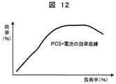
また、蓄電池装置特性データ記憶部DB5の蓄電池システムの特性情報としては、図11のようなPCS(power control system)効率と負荷率の関係や、図12のようなPCSと電池を含んだ負荷率と効率の関係などの情報を含むものとするのがよい。図11のPCS効率は負荷率が高いほど効率が高くなる傾向を示すが、電池と組み合わされた場合には、負荷率が高いと効率が低下する電池特性が支配的となり、山状の効率を示す。このため、最高効率付近での運転を行うには、各蓄電池特性を反映した蓄電池の組合せとするのがよい。 Further, as the storage battery system characteristic information of the storage battery device characteristic data storage unit DB5, the relation between the PCS (power control system) efficiency and the load factor as shown in FIG. 11 or the load factor including the PCS and the battery as shown in FIG. And information such as efficiency relationships. The PCS efficiency of FIG. 11 shows a tendency that the higher the load factor, the higher the efficiency. However, when combined with the battery, the battery characteristics that the efficiency decreases when the load factor is high are dominant, and the mountain-shaped efficiency is reduced. Show. For this reason, in order to perform driving | operation near the maximum efficiency, it is good to set it as the combination of the storage battery reflecting each storage battery characteristic.
蓄電池装置スケジュール計算部52では、蓄電池装置余力最大集約量計算部45で求めた余力最大集約量をスケジュール化するに当り、時間帯別発電コストデータ記憶部DB4に記憶された電力系統側のコストの情報と、蓄電池装置特性データ記憶部DB5に記憶された蓄電池側の効率の情報とを加味して、指定された時間内に稼動可能な蓄電池装置と、稼動時間帯、出力などを決定する。
In the storage battery device
蓄電池装置スケジュール計算部52で求めた計算結果は、蓄電池スケジュール計算結果記憶部DB6に記憶される。この記憶データ(余力の集約結果、更にこのときのコストなど)は、図1の応答信号R1としてデータ送信部48を介して中央給電指令所F内の蓄電池群運用指令装置3に送信される。
The calculation results obtained by the storage battery device
蓄電池群運用指令装置3では、この内容を入力して経済負荷配分計算に取り込む。経済負荷配分計算での蓄電池分の取り扱いは種々あり得るが、蓄電池に最優先に配分し、残りの電力量を火力、水力、原子力で配分するという考えがある。また、瞬時の負荷変動に対応しやすいので、負荷変動が予定把握されている時間帯に集中的に投入するという考えもあり得る。いずれにせよ、蓄電池分は経済負荷配分に組み込まれて、その結果として、最終的な運用指令C2が決定される。
The storage battery group
運用指令C2は蓄電池管理装置4に送られ、指令受信部49を経由して蓄電池スケジュール計算結果記憶部DB6に送られる。このときの運用指令C2は、蓄電池装置6の組み合わせパターンの情報と活用量を含む。この結果として、蓄電池装置スケジュール計算部52で当初準備した稼動可能な蓄電池装置6の中から、運用指令C2に従い選択された蓄電池についての蓄電池スケジュールが、データ送信部54を介して、需要家の蓄電池装置6へ送信されて、所定の時間に、所定の操作を行うことで、電力系統全体としての経済負荷配分運用に貢献する。
The operation command C2 is sent to the storage
ここで、最大余力集約量計算により求められ蓄電池スケジュール計算結果記憶部DB6に記憶された蓄電池群による電力配分計画を初期計画とするときに、経済負荷配分の検討結果を受けた運用指令C2よる電力配分計画は最終計画と称すべきものである。初期計画と最終計画は同じ内容である場合も、変更される場合もある。 Here, when the power distribution plan based on the storage battery group obtained by the calculation of the maximum remaining power aggregation amount and stored in the storage battery schedule calculation result storage unit DB6 is set as the initial plan, the power based on the operation instruction C2 that has received the examination result of the economic load distribution The allocation plan should be called the final plan. The initial plan and final plan may have the same content or may be changed.
図8に示す本発明の実施例では以上のように構成されて、蓄電池装置による電力系統の運用改善に貢献する。なお、蓄電池管理装置4と、中央給電指令所F内の蓄電池群運用指令装置3と、更には運転員の作業、機能分担により、幾つかの装置構成、あるいは運用手法とすることが考えられる。
The embodiment of the present invention shown in FIG. 8 is configured as described above and contributes to the improvement of the operation of the power system by the storage battery device. In addition, it is possible to use some apparatus configurations or operation methods depending on the storage
例えば、蓄電池群運用指令装置3は、経済負荷配分計算を最初に実行し、ここで定めた時間帯と電力量を蓄電池運用指令C1として指定し、蓄電池管理装置4はこの要求を満足する蓄電池装置の組み合わせまで決定するものとすることができる。この場合には、応答信号R1、第2の運用指令C2の処理を実行しない。
For example, the storage battery group
あるいは、蓄電池群運用指令装置3は、蓄電池運用指令C1として時間帯のみ指定し、蓄電池管理装置4はこの時間帯に稼動可能な蓄電池装置と全電力量を計算し、蓄電池群運用指令装置3または運転員がこの中から要求を満足する蓄電池装置の組み合わせを決定する運用とすることができる。
Alternatively, the storage battery group
このように、装置構成する場合は、あるいは機能分担する場合など、幾つかの変形構成を採用することができるが、本発明の趣旨としては電力系統の経済負荷配分の全体運用の中に蓄電池装置を組み込むことである。経済負荷配分の中に蓄電池装置を組み込むうえで、本発明の趣旨を逸脱しない範囲での多くの変更が可能なことは言うまでもない。 As described above, when the device is configured or when the functions are shared, some modified configurations can be adopted. However, the gist of the present invention is that the storage battery device is included in the entire operation of the economic load distribution of the power system. Is to incorporate. Needless to say, many changes can be made without departing from the spirit of the present invention in incorporating the storage battery device into the economic load distribution.
次に、初期計画を修正し、最終計画を求めたときの運用パターンについて、蓄電池装置を4台でシミュレーションした時のケースについて説明する。なお初期計画とは、需要家の蓄電池装置6の空き容量を、最大限活用するときの最大出力を計算して蓄電池計画としたものである。この初期計画の算出には、図4の蓄電池の出力、容量、SOCなどの制約条件、図10のインセンティブコスト情報、図9の時間毎の発電コストが反映されており、各蓄電池の放電出力最大化、コスト最小化とされている。
Next, an operation pattern when the initial plan is corrected and the final plan is obtained will be described for a case where four storage battery devices are simulated. The initial plan is a storage battery plan by calculating the maximum output when the available capacity of the
ここでは、初期に計算した計画に変更があった場合に、再計算をしなおし制約条件を満たす最適解を求めることが可能であることを示す。なお、再計算は蓄電池群運用指令装置3と蓄電池管理装置4のどちらで実行することも可能である。その場合に計算に必要な情報は適宜融通される。
Here, it is shown that when there is a change in the initially calculated plan, recalculation can be performed again to obtain an optimal solution that satisfies the constraint conditions. The recalculation can be executed by either the storage battery group
図13から図16は、それぞれ蓄電池6a、蓄電池6b、蓄電池6c、蓄電池6dのグラフであり、これらのグラフで、横軸に1日の時間、縦軸に充放電(kw)と、SOC(kwh)を表示している。充放電の初期計画を白抜きの棒グラフ、最終計画を黒い棒グラフで示している。また、SOCの初期計画を白丸の折れ線グラフ、最終計画を黒四角の折れ線グラフで示している。棒グラフについて、白と黒が交互に表示された部分は、初期計画と最終計画が同じ(変更なし)であることを意味している。また折れ線グラフについて、丸の部分が黒のみの表記があり白丸がない場合には、初期計画と最終計画が同じ(変更なし)であることを意味している。
FIG. 13 to FIG. 16 are graphs of the
図13から図16の4つの蓄電池装置は、いずれも早朝の時間帯に充電を行い、昼間から夕刻にかけて放電を実施している。そして、白表示の初期計画では、図13から図16の4つの蓄電池装置の合計で、所望のパターンの放電量を確保している。 Each of the four storage battery devices shown in FIGS. 13 to 16 is charged in the early morning hours and discharged from daytime to evening. And in the initial plan of white display, the discharge amount of a desired pattern is ensured by the total of the four storage battery apparatuses of FIGS.
最終計画では、15時に40kWの出力となるように、中央給電指令所Fからの蓄電池運用指令C2が変更設定されたものとする。この場合に、目的関数をコスト最小化にして再計算している。最終的には、特に蓄電池6bと蓄電池6dの放電パターンにおいて変更が大きく現れ、13時から15時までの最大指定時刻に集中し、初期計画からシフトしていることがわかる。以上のように、初期計画から変更してもコスト最小の制約条件を満たしたまま、変更することが出来ることがわかる。
In the final plan, it is assumed that the storage battery operation command C2 from the central power supply command station F is changed and set so that the output is 40 kW at 15:00. In this case, the objective function is recalculated with cost minimization. Eventually, it can be seen that changes appear particularly in the discharge patterns of the
さらに図13から図15の条件のもとで出力最大値を計算したあと、出力を設定して、コスト最小化となる蓄電池の計画のうち、出力が最大のケースを考慮した。図17から図20は、初期計画と最終計画の蓄電池6aから蓄電池6dまでの充放電パターンを示したものである。蓄電池6aと蓄電池6bはインセンティブコストが安いためスケジュールの変更が大きく、パターン指定時刻以外の放電量は低減していることがわかる。蓄電池6cと蓄電池6dはインセンティブコストが高いためスケジュールが変化していないことがわかる。以上のように、初期計画から変更しても制約条件を満たしたまま、容易に変更することも出来ることがわかる。
Further, after calculating the maximum output value under the conditions of FIG. 13 to FIG. 15, the output is set, and the case of the maximum output among the storage battery plans for minimizing the cost is considered. FIGS. 17 to 20 show charge / discharge patterns from the
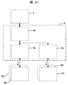
なお、図1において蓄電池管理装置4を構成するに当たり、電力系統の蓄電池装置の数が多い場合や、負荷分散のため分割した方が管理しやすい場合には、図21のように蓄電池管理装置4を階層化して構成することが可能である。例えば4aの部分に計算部や記憶部を配置し、4b、4cを地域的に分散してデータ受信部やデータ送信部を中心に配置する。あるいは、4aを設けず、複数の図8装置4b、4cを地域的に分散配置することであってもよい。
In the configuration of the storage
B:母線、C:蓄電池運用指令、DB1:制約データ記憶部、DB2:蓄電池パターン設定記憶部、DB3:要求パターンデータ記憶部、DB4:時間帯別発電コストデータ記憶部、DB5:特性データ記憶部、DB6:蓄電池スケジュール計算結果記憶部、E:経済負荷配分制御装置、F:中央給電指令所、G1:火力発電機、G2:水力発電機、G3:原子力発電機、Pd:電力要求指令、T:変圧器、Li:送電線、Ld:負荷、3:蓄電池群運用指令装置、4:蓄電池管理装置、6:蓄電池装置、42:蓄電池パターン設定部、44:データ受信部、45:蓄電池装置余力最大集約量計算部、52:蓄電池装置スケジュール計算部 B: Busbar, C: Storage battery operation command, DB1: Constraint data storage unit, DB2: Storage battery pattern setting storage unit, DB3: Request pattern data storage unit, DB4: Power generation cost data storage unit by time zone, DB5: Characteristic data storage unit DB6: Storage battery schedule calculation result storage unit, E: Economic load distribution control device, F: Central power supply command station, G1: Thermal power generator, G2: Hydroelectric power generator, G3: Nuclear power generator, Pd: Power request command, T : Transformer, Li: power transmission line, Ld: load, 3: storage battery group operation command device, 4: storage battery management device, 6: storage battery device, 42: storage battery pattern setting unit, 44: data receiving unit, 45: remaining capacity of storage battery device Maximum aggregate amount calculation unit, 52: Storage battery device schedule calculation unit
Claims (18)
予定日の予定時間帯に電力供給可能な前記蓄電池による電力量を求め、この蓄電池による電力量を含めた電力系統の経済負荷配分計算を実施し、定められた前記蓄電池について、前記予定日の予定時間帯に前記蓄電池による電力供給を実行することを特徴とする電力系統の運用方法。 In an operation method of a power system including a plurality of storage battery devices and a plurality of generators,
Obtain the amount of power from the storage battery that can supply power in the scheduled time zone on the scheduled date, perform an economic load distribution calculation of the power system including the amount of power by the storage battery, and for the predetermined storage battery, schedule the scheduled date A method for operating an electric power system, wherein power supply by the storage battery is executed in a time zone.
前記予定日の予定時間帯に電力供給可能な前記蓄電池による電力量を求めるときに、個々の蓄電池装置の需要家における運転計画を考慮することを特徴とする電力系統の運用方法。 In the operation method of the electric power system according to claim 1,
A method for operating an electric power system, wherein an operation plan for a consumer of each storage battery device is taken into account when determining the amount of power by the storage battery that can supply power during the scheduled time zone on the scheduled date.
前記予定日の予定時間帯に電力供給可能な前記蓄電池による電力量を求めるときに、個々の蓄電池装置の出力(kw)と容量(kwh)からの制約条件を考慮することを特徴とする電力系統の運用方法。 In the operation method of the electric power system according to claim 1 or claim 2,
A power system characterized by considering a constraint condition from the output (kw) and capacity (kwh) of each storage battery device when determining the amount of power from the storage battery that can supply power in the scheduled time zone on the scheduled date Operation method.
前記予定日の予定時間帯に電力供給可能な前記蓄電池による電力量を求めるときに、個々の蓄電池装置の効率を考慮することを特徴とする電力系統の運用方法。 In the operation method of the electric power system in any one of Claims 1-3,
A method of operating an electric power system, wherein the efficiency of each storage battery device is taken into account when determining the amount of power by the storage battery that can supply power during the scheduled time zone on the scheduled date.
前記予定日の予定時間帯に電力供給可能な前記蓄電池による電力量を求めるときに、電力系統における時間帯別コストを考慮することを特徴とする電力系統の運用方法。 In the operation method of the electric power system in any one of Claims 1-4,
A method for operating an electric power system characterized by considering a time-specific cost in an electric power system when determining the amount of electric power by the storage battery capable of supplying electric power in the scheduled time period on the scheduled date.
前記予定日の予定時間帯に電力供給可能な前記蓄電池による電力量を求めるときに、予定時間帯での蓄電池使用ができるように、事前に蓄電池の運用状況を変更することを特徴とする電力系統の運用方法。 In the operating method of the electric power system in any one of Claims 1-5,
When determining the amount of power from the storage battery that can supply power during the scheduled time zone on the scheduled date, the operating state of the storage battery is changed in advance so that the storage battery can be used in the scheduled time zone. Operation method.
予定日の予定時間帯を指定し、
当該時間帯に電力供給可能な前記蓄電池による最大電力量を求め、
この蓄電池による最大電力量を含めた電力系統の経済負荷配分計算を実施し、
経済負荷配分計算の結果定められた条件下で前記蓄電池により供給可能な電力量を定め、
前記再決定された電力量の蓄電池について、予定時間帯に前記蓄電池による電力供給を実行することを特徴とする電力系統の運用方法。 In an operation method of a power system including a plurality of storage battery devices and a plurality of generators,
Specify the scheduled time zone for the scheduled date,
Find the maximum amount of power by the storage battery that can supply power during the time period,
The calculation of the economic load distribution of the power system, including the maximum amount of power generated by this storage battery,
Determine the amount of power that can be supplied by the storage battery under the conditions determined as a result of the economic load distribution calculation,
A method of operating an electric power system, wherein power supply by the storage battery is executed during a scheduled time period for the re-determined power storage battery.
予定日の予定時間帯に電力供給可能な前記蓄電池による電力量を含めた電力系統の経済負荷配分計算を実施し、前記予定日の予定時間帯に前記蓄電池による電力供給を実行することを特徴とする電力系統の運用方法。 In an operation method of a power system including a plurality of storage battery devices and a plurality of generators,
Performing an economic load distribution calculation of the power system including the amount of power by the storage battery that can supply power in the scheduled time zone on the scheduled date, and executing power supply by the storage battery in the scheduled time zone on the scheduled date, To operate the power system.
予定日の予定時間帯を指定する手段、
当該時間帯に電力供給可能な前記蓄電池による最大電力量を求める電力量算出手段、この蓄電池による最大電力量を含めた電力系統の経済負荷配分計算を実施する経済負荷配分計算手段、
経済負荷配分計算の結果定められた条件下で前記蓄電池により供給可能な電力量を定める電力量決定手段、
前記再決定された電力量の蓄電池について、予定時間帯に前記蓄電池による電力供給を実行する蓄電池制御手段を備えることを特徴とする電力系統の運用装置。 In the operation system of the power system including a plurality of storage battery devices and a plurality of generators,
Means to specify the scheduled time zone of the scheduled date,
Power amount calculating means for obtaining the maximum power amount by the storage battery capable of supplying power during the time period, economic load distribution calculating means for performing economic load distribution calculation of the power system including the maximum power amount by the storage battery,
An electric energy determining means for determining an electric energy that can be supplied by the storage battery under a condition determined as a result of an economic load distribution calculation;
An operation apparatus for an electric power system comprising storage battery control means for executing power supply by the storage battery during a scheduled time period for the re-determined power storage battery.
前記電力量算出手段は、個々の蓄電池装置の需要家における運転計画を入力する手段を備え、予定日の予定時間帯に電力供給可能な前記蓄電池による電力量を求めるときに、前記運転計画を考慮することを特徴とする電力系統の運用装置。 In the power system operation device according to claim 9,
The power amount calculating means includes means for inputting an operation plan for a consumer of each storage battery device, and considers the operation plan when obtaining the amount of power by the storage battery that can supply power in a scheduled time zone on a scheduled date. A power system operation device characterized by:
前記電力量算出手段は、個々の蓄電池装置の出力(kw)と容量(kwh)についての制約データを入力する手段を備え、予定日の予定時間帯に電力供給可能な前記蓄電池による電力量を求めるときに、前記出力(kw)と容量(kwh)からの制約条件を考慮することを特徴とする電力系統の運用装置。 In the power system operation device according to claim 9 or claim 10,
The power amount calculation means includes means for inputting constraint data regarding the output (kw) and capacity (kwh) of each storage battery device, and obtains the power amount by the storage battery that can supply power in the scheduled time zone on the scheduled date. Sometimes, a power system operating device is characterized by considering a constraint condition from the output (kw) and capacity (kwh).
前記電力量算出手段は、個々の蓄電池装置の効率を入力する手段を備え、予定日の予定時間帯に電力供給可能な前記蓄電池による電力量を求めるときに、個々の蓄電池装置の効率を考慮することを特徴とする電力系統の運用装置。 In the operation apparatus of the electric power system in any one of Claims 9-11,
The power amount calculation means includes means for inputting the efficiency of each storage battery device, and considers the efficiency of each storage battery device when determining the amount of power by the storage battery that can supply power in the scheduled time zone on the scheduled date. A power system operation device characterized by that.
前記電力量算出手段は、電力系統における時間帯別コストを入力する手段を備え、予定日の予定時間帯に電力供給可能な前記蓄電池による電力量を求めるときに、電力系統における時間帯別コストを考慮することを特徴とする電力系統の運用装置。 In the power system operation device according to any one of claims 9 to 12,
The power amount calculating means includes means for inputting a cost for each time zone in the power system, and when calculating the power amount by the storage battery that can supply power in a scheduled time zone on a scheduled date, the cost for each time zone in the power system is calculated. A power system operating device characterized by consideration.
前記電力量算出手段は、予定日の予定時間帯に電力供給可能な前記蓄電池による電力量を求めるときに、予定時間帯での蓄電池使用ができるように、事前に蓄電池の運用状況を変更する制御指令を与える制御手段を備えることを特徴とする電力系統の運用装置。 In the operation apparatus of the electric power system in any one of Claim 9 to Claim 13,
The power amount calculation means is a control that changes the operation state of the storage battery in advance so that the storage battery can be used in the scheduled time zone when obtaining the power amount by the storage battery that can supply power in the scheduled time zone on the scheduled date. A power system operation device comprising control means for giving a command.
中央給電指令装置に備えられ予定日の予定時間帯を指定する手段、
蓄電池管理装置に備えられ当該時間帯に電力供給可能な前記蓄電池による最大電力量を求める電力量算出手段、
中央給電指令装置に備えられこの蓄電池による最大電力量を含めた電力系統の経済負荷配分計算を実施する経済負荷配分計算手段、および経済負荷配分計算の結果定められた条件下で前記蓄電池により供給可能な電力量を定める電力量決定手段、
蓄電池管理装置に備えられ前記再決定された電力量の蓄電池について、予定時間帯に前記蓄電池による電力供給を指示する指示手段、
電力系統各所に設置され充放電制御機能と通信機能とを有し、前記蓄電池管理装置に蓄電池情報を送信するとともに、前記蓄電池管理装置からの電力供給指示に従い充放電制御を実行する蓄電池装置を備えることを特徴とする電力系統の運用装置。 A power system operation device that operates a power system including a plurality of storage battery devices and a plurality of generators according to a command from a central power supply command device,
Means for specifying the scheduled time zone of the scheduled date, provided in the central power supply command device;
A power amount calculating means for obtaining a maximum power amount by the storage battery that is provided in the storage battery management device and can supply power in the time zone,
Economic load distribution calculation means for carrying out the economic load distribution calculation of the power system including the maximum amount of power by the storage battery provided in the central power supply command device, and supply by the storage battery under the conditions determined as a result of the economic load distribution calculation Electric energy determination means for determining the amount of electric power,
Instructing means for instructing power supply by the storage battery during a scheduled time period for the re-determined storage battery of the storage battery management device.
A storage battery device that is installed in various places of the power system, has a charge / discharge control function and a communication function, transmits storage battery information to the storage battery management device, and executes charge / discharge control according to a power supply instruction from the storage battery management device. A power system operation device characterized by that.
前記蓄電池管理装置に送信する蓄電池情報として、当該蓄電池装置の運転計画、当該蓄電池装置の制約データ、蓄電池装置の効率を含むことを特徴とする電力系統の運用装置。 The power system operation device according to claim 15,
The storage battery information to be transmitted to the storage battery management device includes an operation plan of the storage battery device, constraint data of the storage battery device, and efficiency of the storage battery device.
前記蓄電池管理装置は、中央給電指令装置から電力系統における時間帯別コストを得ることを特徴とする電力系統の運用装置。 In the operation apparatus of the electric power system of Claim 15 or Claim 16,
The storage battery management device obtains a cost for each time zone in the power system from a central power supply command device.
蓄電池管理装置は、前記中央給電指令装置から指定された予定日の予定時間帯に電力供給可能な前記蓄電池による最大電力量を求める電力量算出手段と、
中央給電指令装置での経済負荷配分計算の結果定められた前記蓄電池装置により供給可能な電力量を前記蓄電池装置に送信する送信手段を備える
ことを特徴とする蓄電池管理装置。 A storage battery device installed at various places in the power system, having a charge / discharge control function and a communication function, and executing an economic load distribution calculation taking into account the amount of power supplied by the storage battery device, and issuing output commands to a plurality of generators of the power system In the storage battery management device connected to the central power supply command device to give,
The storage battery management device is a power amount calculating means for obtaining a maximum power amount by the storage battery capable of supplying power in a scheduled time zone designated by the central power supply command device,
A storage battery management apparatus comprising: a transmission unit configured to transmit, to the storage battery apparatus, an amount of power that can be supplied by the storage battery apparatus determined as a result of an economic load distribution calculation in a central power supply command apparatus.
Priority Applications (6)
| Application Number | Priority Date | Filing Date | Title |
|---|---|---|---|
| JP2012031262A JP6088737B2 (en) | 2012-02-16 | 2012-02-16 | Power system operation method, operation device, and storage battery management device |
| CN201380008552.0A CN104170201B (en) | 2012-02-16 | 2013-02-13 | The application method of power system, with device and accumulator management device |
| PCT/JP2013/053343 WO2013122079A1 (en) | 2012-02-16 | 2013-02-13 | Method and device for operating power system, and rechargeable-battery management device |
| IN6534DEN2014 IN2014DN06534A (en) | 2012-02-16 | 2013-02-13 | |
| EP13749828.3A EP2816699B1 (en) | 2012-02-16 | 2013-02-13 | Method and device for operating power system, and rechargeable-battery management device |
| US14/377,277 US10291034B2 (en) | 2012-02-16 | 2013-02-13 | Method and device for operating power system, and rechargeable-battery management device |
Applications Claiming Priority (1)
| Application Number | Priority Date | Filing Date | Title |
|---|---|---|---|
| JP2012031262A JP6088737B2 (en) | 2012-02-16 | 2012-02-16 | Power system operation method, operation device, and storage battery management device |
Publications (3)
| Publication Number | Publication Date |
|---|---|
| JP2013169089A true JP2013169089A (en) | 2013-08-29 |
| JP2013169089A5 JP2013169089A5 (en) | 2014-11-27 |
| JP6088737B2 JP6088737B2 (en) | 2017-03-01 |
Family
ID=48984189
Family Applications (1)
| Application Number | Title | Priority Date | Filing Date |
|---|---|---|---|
| JP2012031262A Active JP6088737B2 (en) | 2012-02-16 | 2012-02-16 | Power system operation method, operation device, and storage battery management device |
Country Status (6)
| Country | Link |
|---|---|
| US (1) | US10291034B2 (en) |
| EP (1) | EP2816699B1 (en) |
| JP (1) | JP6088737B2 (en) |
| CN (1) | CN104170201B (en) |
| IN (1) | IN2014DN06534A (en) |
| WO (1) | WO2013122079A1 (en) |
Cited By (7)
| Publication number | Priority date | Publication date | Assignee | Title |
|---|---|---|---|---|
| JP2016039648A (en) * | 2014-08-05 | 2016-03-22 | 富士電機株式会社 | Operation schedule generation device, operation schedule generation method, and program |
| CN105634012A (en) * | 2016-02-16 | 2016-06-01 | 国网山东省电力公司淄博供电公司 | Distributed type power generation and microgrid intelligent monitoring control method |
| JP2017099039A (en) * | 2015-11-18 | 2017-06-01 | 株式会社日立製作所 | Wind farm and control method therefor |
| JP2017516448A (en) * | 2014-05-21 | 2017-06-15 | ホアウェイ・テクノロジーズ・カンパニー・リミテッド | Electric energy dispatch method and apparatus, and power management method and apparatus |
| KR101759819B1 (en) * | 2015-03-16 | 2017-07-31 | 가부시끼가이샤 도시바 | Storage battery control device and storage battery control method |
| US10491010B2 (en) | 2015-03-24 | 2019-11-26 | Denso Corporation | Control apparatus for controlling the charging and discharging of storage batteries through a power converter |
| JP2020150759A (en) * | 2019-03-15 | 2020-09-17 | 株式会社デンソー | Power control device |
Families Citing this family (14)
| Publication number | Priority date | Publication date | Assignee | Title |
|---|---|---|---|---|
| JP2014233934A (en) * | 2013-06-04 | 2014-12-15 | キヤノン株式会社 | Electronic device, method for controlling the same, and program |
| WO2015044466A1 (en) * | 2013-09-30 | 2015-04-02 | Acciona Energía, S. A. | Method for controlling power fluctuation ramps having energy storage systems in plants for intermittent energy generation |
| JPWO2015129734A1 (en) * | 2014-02-25 | 2017-03-30 | 住友電気工業株式会社 | Energy management system, energy management method, and computer program |
| JP2015186361A (en) * | 2014-03-25 | 2015-10-22 | 株式会社日立製作所 | Power adjustment controller and power adjustment control method |
| US10128656B2 (en) * | 2014-06-17 | 2018-11-13 | Samsung Sdi Co., Ltd. | Power assist unit and power assist system |
| JP2016220450A (en) * | 2015-05-22 | 2016-12-22 | 三菱重工業株式会社 | Power supply controller, power supply system, power source control method, and program |
| US9426320B1 (en) * | 2015-05-26 | 2016-08-23 | Kabushiki Kaisha Toshiba | Image processing apparatus having a power supply source selector |
| WO2017159147A1 (en) * | 2016-03-17 | 2017-09-21 | 日本電気株式会社 | Control device, control method, and program |
| JP6703777B2 (en) * | 2016-10-19 | 2020-06-03 | 株式会社東芝 | Power generation planning device, power generation planning method, and power generation planning program |
| KR101904846B1 (en) * | 2016-12-09 | 2018-10-10 | 효성중공업 주식회사 | Method for Operating ESS Optimally and Efficiently |
| US10658841B2 (en) * | 2017-07-14 | 2020-05-19 | Engie Storage Services Na Llc | Clustered power generator architecture |
| CN110826240B (en) * | 2019-11-13 | 2023-04-21 | 瑞浦兰钧能源股份有限公司 | Secondary storage battery simulation method |
| US11658486B2 (en) | 2020-05-15 | 2023-05-23 | Honeywell International Inc. | Energy control for energy storage systems |
| WO2024050441A1 (en) * | 2022-08-30 | 2024-03-07 | Power Management Holdings (U.S.), Inc. | Energy dispatch optimization using a fleet of distributed energy resources |
Citations (4)
| Publication number | Priority date | Publication date | Assignee | Title |
|---|---|---|---|---|
| JP2006094649A (en) * | 2004-09-24 | 2006-04-06 | Kansai Electric Power Co Inc:The | Power generation planning method and power generation planning apparatus using secondary battery |
| JP2011114900A (en) * | 2009-11-25 | 2011-06-09 | Fuji Electric Systems Co Ltd | Apparatus and method for controlling supply and demand of micro-grid |
| JP2012010452A (en) * | 2010-06-23 | 2012-01-12 | Tokyo Electric Power Co Inc:The | Operation apparatus for batteries in power system |
| WO2012014332A1 (en) * | 2010-07-30 | 2012-02-02 | 株式会社 東芝 | Output distribution control apparatus |
Family Cites Families (22)
| Publication number | Priority date | Publication date | Assignee | Title |
|---|---|---|---|---|
| US8315898B2 (en) * | 2002-10-30 | 2012-11-20 | Palo Alto Research Center, Incorporated | Planning and scheduling reconfigurable systems around off-line resources |
| JP4187620B2 (en) | 2003-09-22 | 2008-11-26 | 株式会社明電舎 | A generator start / stop plan creation method and apparatus, and a recording medium for recording a processing program of the start / stop plan creation apparatus. |
| JP2005312138A (en) * | 2004-04-19 | 2005-11-04 | Canon Inc | Power controller, power generation system and power system |
| JP4445361B2 (en) | 2004-09-24 | 2010-04-07 | 関西電力株式会社 | Power system control method and power system control apparatus using secondary battery |
| US7590472B2 (en) * | 2006-11-09 | 2009-09-15 | Gridpoint, Inc. | Energy arbitrage by load shifting |
| JP5178242B2 (en) * | 2008-02-29 | 2013-04-10 | 株式会社東芝 | Energy storage device operation plan creation method and operation plan creation device |
| CN102138247B (en) * | 2008-09-30 | 2014-03-12 | 日本碍子株式会社 | Method for controlling sodium-sulfur battery |
| JP5350942B2 (en) | 2009-08-25 | 2013-11-27 | 株式会社東芝 | Supply / demand control device for power system, supply / demand control program, and recording medium thereof |
| JP2011083082A (en) * | 2009-10-05 | 2011-04-21 | Panasonic Electric Works Co Ltd | Power storage system |
| FR2952247B1 (en) * | 2009-10-29 | 2012-01-06 | Commissariat Energie Atomique | MANAGING THE RECHARGE OF A BATTERY PARK |
| JP5402569B2 (en) | 2009-11-26 | 2014-01-29 | 富士電機株式会社 | Economic load distribution control device and economic load distribution control method |
| JP5659506B2 (en) * | 2010-03-03 | 2015-01-28 | 富士通株式会社 | Power leveling control device, power leveling control method, and program |
| JP5582831B2 (en) * | 2010-03-11 | 2014-09-03 | 株式会社東芝 | Solar power system |
| JP5646205B2 (en) * | 2010-04-28 | 2014-12-24 | 株式会社東芝 | Power consumption management system, power consumption management device used therefor, power consumption management method, central power supply management device, power supply management method |
| JP5386444B2 (en) * | 2010-06-30 | 2014-01-15 | 株式会社日立製作所 | Storage battery control device, storage battery control method, and storage battery specification determination method |
| US9335748B2 (en) * | 2010-07-09 | 2016-05-10 | Emerson Process Management Power & Water Solutions, Inc. | Energy management system |
| JP2012039821A (en) * | 2010-08-10 | 2012-02-23 | Toshiba Corp | Power fluctuation relaxing device of power generating system and power fluctuation relaxing method |
| CA2862904C (en) * | 2011-02-01 | 2020-07-28 | S&C Electric Company | Distributed energy storage system and method of distributing energy |
| WO2012127585A1 (en) * | 2011-03-18 | 2012-09-27 | 富士通株式会社 | Operation schedule creating method, operation schedule creating apparatus, and operation schedule creating program |
| CN103299506B (en) * | 2011-03-31 | 2016-03-09 | 松下电器产业株式会社 | Power control unit, electrical control method, program, integrated circuit and storage battery module |
| CN103597689B (en) * | 2011-04-08 | 2016-08-17 | 艾思玛太阳能技术股份公司 | The load management optimized |
| US8725306B2 (en) * | 2011-08-29 | 2014-05-13 | Sap Ag | Vehicle electric charging schedule selection and evolution based on multiple weighted charging objectives |
-
2012
- 2012-02-16 JP JP2012031262A patent/JP6088737B2/en active Active
-
2013
- 2013-02-13 CN CN201380008552.0A patent/CN104170201B/en active Active
- 2013-02-13 WO PCT/JP2013/053343 patent/WO2013122079A1/en active Application Filing
- 2013-02-13 IN IN6534DEN2014 patent/IN2014DN06534A/en unknown
- 2013-02-13 US US14/377,277 patent/US10291034B2/en active Active
- 2013-02-13 EP EP13749828.3A patent/EP2816699B1/en active Active
Patent Citations (4)
| Publication number | Priority date | Publication date | Assignee | Title |
|---|---|---|---|---|
| JP2006094649A (en) * | 2004-09-24 | 2006-04-06 | Kansai Electric Power Co Inc:The | Power generation planning method and power generation planning apparatus using secondary battery |
| JP2011114900A (en) * | 2009-11-25 | 2011-06-09 | Fuji Electric Systems Co Ltd | Apparatus and method for controlling supply and demand of micro-grid |
| JP2012010452A (en) * | 2010-06-23 | 2012-01-12 | Tokyo Electric Power Co Inc:The | Operation apparatus for batteries in power system |
| WO2012014332A1 (en) * | 2010-07-30 | 2012-02-02 | 株式会社 東芝 | Output distribution control apparatus |
Cited By (10)
| Publication number | Priority date | Publication date | Assignee | Title |
|---|---|---|---|---|
| JP2017516448A (en) * | 2014-05-21 | 2017-06-15 | ホアウェイ・テクノロジーズ・カンパニー・リミテッド | Electric energy dispatch method and apparatus, and power management method and apparatus |
| US10505381B2 (en) | 2014-05-21 | 2019-12-10 | Huawei Technologies Co., Ltd. | Electric energy dispatch method and apparatus, and power management method and apparatus |
| JP2016039648A (en) * | 2014-08-05 | 2016-03-22 | 富士電機株式会社 | Operation schedule generation device, operation schedule generation method, and program |
| KR101759819B1 (en) * | 2015-03-16 | 2017-07-31 | 가부시끼가이샤 도시바 | Storage battery control device and storage battery control method |
| US10297877B2 (en) | 2015-03-16 | 2019-05-21 | Kabushiki Kaisha Toshiba | Storage battery control device and storage battery control method |
| US10491010B2 (en) | 2015-03-24 | 2019-11-26 | Denso Corporation | Control apparatus for controlling the charging and discharging of storage batteries through a power converter |
| JP2017099039A (en) * | 2015-11-18 | 2017-06-01 | 株式会社日立製作所 | Wind farm and control method therefor |
| CN105634012A (en) * | 2016-02-16 | 2016-06-01 | 国网山东省电力公司淄博供电公司 | Distributed type power generation and microgrid intelligent monitoring control method |
| JP2020150759A (en) * | 2019-03-15 | 2020-09-17 | 株式会社デンソー | Power control device |
| JP7151570B2 (en) | 2019-03-15 | 2022-10-12 | 株式会社デンソー | power controller |
Also Published As
| Publication number | Publication date |
|---|---|
| EP2816699B1 (en) | 2019-11-06 |
| WO2013122079A1 (en) | 2013-08-22 |
| CN104170201B (en) | 2017-10-03 |
| EP2816699A1 (en) | 2014-12-24 |
| EP2816699A4 (en) | 2015-11-11 |
| US10291034B2 (en) | 2019-05-14 |
| JP6088737B2 (en) | 2017-03-01 |
| CN104170201A (en) | 2014-11-26 |
| US20160020613A1 (en) | 2016-01-21 |
| IN2014DN06534A (en) | 2015-06-12 |
Similar Documents
| Publication | Publication Date | Title |
|---|---|---|
| JP6088737B2 (en) | Power system operation method, operation device, and storage battery management device | |
| Choi et al. | Optimal scheduling and operation of the ESS for prosumer market environment in grid-connected industrial complex | |
| Huang et al. | Review of congestion management methods for distribution networks with high penetration of distributed energy resources | |
| JP6145670B2 (en) | Power flow control system, management device, program | |
| EP2688173B1 (en) | Multi-service provision with energy storage system | |
| EP2506383B1 (en) | System and method for operating capacitor banks | |
| JP4783246B2 (en) | Power system control device and method using secondary battery, power generation planning device, real-time control device, and power system control system | |
| CN102509167B (en) | Photovoltaic power generation and energy management system based on virtual power plant | |
| CN103825304A (en) | Method of controlling power network | |
| JP6050938B2 (en) | Power supply system, power supply control device, power supply method and program | |
| JP5998046B2 (en) | Power suppression control system and power suppression control method | |
| EP2916416B1 (en) | Consumer apparatus operation management system and method | |
| JP2013169068A (en) | Power control system | |
| WO2015146200A1 (en) | Power management system, power management method, and control device | |
| JP2006288014A (en) | Energy supply system and supply control system | |
| JP2013143816A (en) | Power supply system, power supply control device, power supply method and program | |
| JP5951747B2 (en) | Power system controller | |
| Shaaban et al. | Day-ahead optimal scheduling for demand side management in smart grids | |
| JP2017046507A (en) | System stabilization system | |
| Astaneh et al. | A novel technique to enhance demand responsiveness: An EV based test case | |
| JP2013169067A (en) | Power control system | |
| Kapoor et al. | Voltage Regulation in Distribution System using Demand Response | |
| WO2021152667A1 (en) | Power supply management apparatus and power supply management method | |
| Bućko et al. | Delivery of ancillary services in distribution power systems | |
| JP2016063719A (en) | Power supply system, power use price calculation device, power supply method, power use price calculation method, and program |
Legal Events
| Date | Code | Title | Description |
|---|---|---|---|
| A521 | Request for written amendment filed |
Free format text: JAPANESE INTERMEDIATE CODE: A523 Effective date: 20141009 |
|
| A621 | Written request for application examination |
Free format text: JAPANESE INTERMEDIATE CODE: A621 Effective date: 20141009 |
|
| A131 | Notification of reasons for refusal |
Free format text: JAPANESE INTERMEDIATE CODE: A131 Effective date: 20160308 |
|
| A521 | Request for written amendment filed |
Free format text: JAPANESE INTERMEDIATE CODE: A523 Effective date: 20160428 |
|
| A131 | Notification of reasons for refusal |
Free format text: JAPANESE INTERMEDIATE CODE: A131 Effective date: 20160719 |
|
| A521 | Request for written amendment filed |
Free format text: JAPANESE INTERMEDIATE CODE: A523 Effective date: 20160913 |
|
| A131 | Notification of reasons for refusal |
Free format text: JAPANESE INTERMEDIATE CODE: A131 Effective date: 20161115 |
|
| A521 | Request for written amendment filed |
Free format text: JAPANESE INTERMEDIATE CODE: A523 Effective date: 20161215 |
|
| TRDD | Decision of grant or rejection written | ||
| A01 | Written decision to grant a patent or to grant a registration (utility model) |
Free format text: JAPANESE INTERMEDIATE CODE: A01 Effective date: 20170131 |
|
| A61 | First payment of annual fees (during grant procedure) |
Free format text: JAPANESE INTERMEDIATE CODE: A61 Effective date: 20170206 |
|
| R150 | Certificate of patent or registration of utility model |
Ref document number: 6088737 Country of ref document: JP Free format text: JAPANESE INTERMEDIATE CODE: R150 |
|
| R250 | Receipt of annual fees |
Free format text: JAPANESE INTERMEDIATE CODE: R250 |
|
| R250 | Receipt of annual fees |
Free format text: JAPANESE INTERMEDIATE CODE: R250 |
|
| R250 | Receipt of annual fees |
Free format text: JAPANESE INTERMEDIATE CODE: R250 |
|
| R250 | Receipt of annual fees |
Free format text: JAPANESE INTERMEDIATE CODE: R250 |
|
| R250 | Receipt of annual fees |
Free format text: JAPANESE INTERMEDIATE CODE: R250 |