JP2013166328A - Recording device - Google Patents
Recording device Download PDFInfo
- Publication number
- JP2013166328A JP2013166328A JP2012031449A JP2012031449A JP2013166328A JP 2013166328 A JP2013166328 A JP 2013166328A JP 2012031449 A JP2012031449 A JP 2012031449A JP 2012031449 A JP2012031449 A JP 2012031449A JP 2013166328 A JP2013166328 A JP 2013166328A
- Authority
- JP
- Japan
- Prior art keywords
- ink
- tube
- recording apparatus
- deformation
- ink tube
- Prior art date
- Legal status (The legal status is an assumption and is not a legal conclusion. Google has not performed a legal analysis and makes no representation as to the accuracy of the status listed.)
- Granted
Links
- 238000007599 discharging Methods 0.000 abstract description 5
- 239000000976 ink Substances 0.000 description 226
- 230000035515 penetration Effects 0.000 description 27
- 230000000694 effects Effects 0.000 description 9
- 230000000149 penetrating effect Effects 0.000 description 9
- 230000009471 action Effects 0.000 description 6
- 239000000463 material Substances 0.000 description 5
- 238000000034 method Methods 0.000 description 4
- 210000000078 claw Anatomy 0.000 description 3
- 230000006866 deterioration Effects 0.000 description 3
- 238000010586 diagram Methods 0.000 description 3
- 238000009434 installation Methods 0.000 description 3
- 230000007246 mechanism Effects 0.000 description 3
- 230000008569 process Effects 0.000 description 3
- 230000003139 buffering effect Effects 0.000 description 2
- 239000000470 constituent Substances 0.000 description 2
- 230000004048 modification Effects 0.000 description 2
- 238000012986 modification Methods 0.000 description 2
- 230000002093 peripheral effect Effects 0.000 description 2
- 230000009467 reduction Effects 0.000 description 2
- 230000001105 regulatory effect Effects 0.000 description 2
- 230000004308 accommodation Effects 0.000 description 1
- 230000005540 biological transmission Effects 0.000 description 1
- 239000003086 colorant Substances 0.000 description 1
- 230000000052 comparative effect Effects 0.000 description 1
- 239000002131 composite material Substances 0.000 description 1
- 239000011162 core material Substances 0.000 description 1
- 230000007423 decrease Effects 0.000 description 1
- 239000013013 elastic material Substances 0.000 description 1
- 238000005516 engineering process Methods 0.000 description 1
- 230000006698 induction Effects 0.000 description 1
- 239000011120 plywood Substances 0.000 description 1
- 230000000452 restraining effect Effects 0.000 description 1
Images


Landscapes
- Ink Jet (AREA)
Abstract
【課題】インクチューブの変形可動部の変形拡大の基づく騒音を低減することにある。
【解決手段】インクを吐出する記録ヘッド5を備え所定の方向に移動可能なヘッドユニット7と、インクが収容されたインク収容部11から送られるインクを前記記録ヘッド5へと導き、前記ヘッドユニット7の前記移動に伴ってU字反転部31を介して追従変形する変形可動部3を有するインクチューブ13と、前記変形可動部の変形拡大側に存在する拡大側構成部材15と、前記拡大側構成部材と前記変形可動部を成すインクチューブとの間に存在し、前記変形拡大するインクチューブが接触する緩衝部90とを備える。
【選択図】図14An object of the present invention is to reduce noise based on deformation expansion of a deformation movable portion of an ink tube.
A head unit having a recording head for discharging ink and capable of moving in a predetermined direction, and ink sent from an ink containing portion containing ink is guided to the recording head, and the head unit 7, an ink tube 13 having a deformable movable portion 3 that follows and deforms via a U-shaped reversing portion 31 in accordance with the movement, an enlargement-side component member 15 present on the deformation enlargement side of the deformable movable portion, and the enlargement side A buffer portion 90 that exists between the component member and the ink tube that forms the deformable movable portion and contacts the ink tube that expands and deforms is provided.
[Selection] Figure 14
Description
本発明は、インクを吐出する記録ヘッドを備え所定の方向に移動可能なヘッドユニットと、インク収容部と前記ヘッドユニットに両端が接続され、前記インク収容部内のインクを前記記録ヘッドへと導く、可撓性を有するインクチューブであって、前記ヘッドユニットの前記移動に伴ってU字反転部を介して追従変形する変形可動部を有するインクチューブと、前記変形可動部の変形拡大側に存在する例えばスキャナー等の拡大側構成部材とを備えた構成のインクジェットプリンター等の記録装置に関するものである。 The present invention includes a recording head that ejects ink, and a head unit that is movable in a predetermined direction, an ink storage section, and both ends connected to the head unit, and guides ink in the ink storage section to the recording head. An ink tube having flexibility, and an ink tube having a deformable movable portion that follows and deforms via a U-shaped reversing portion with the movement of the head unit, and is present on the deformation expansion side of the deformable movable portion. For example, the present invention relates to a recording apparatus such as an ink jet printer having a configuration including an enlarged side component such as a scanner.
この種の記録装置の従来技術として、下記の特許文献1や特許文献2に記載されているものが挙げられる。
これらの記録装置では、前記ヘッドユニットの移動に伴ってU字反転部を介して追従変形する変形可動部を有するインクチューブが記載されている。
Examples of the conventional technology of this type of recording apparatus include those described in
In these recording apparatuses, there is described an ink tube having a deformable movable portion that follows and deforms via a U-shaped reversing portion as the head unit moves.
インクチューブの前記変形可動部の変形量の大きく、またその変形拡大側の近くに他の部材が存在していると、インクチューブの前記変形可動部の変形量の大きさによっては該インクチューブが前記他の部材と衝突し、騒音が発生する虞がある。
しかし、上記従来の記録装置では、その騒音問題については全く考慮されていない。
If the deformation amount of the deformation movable portion of the ink tube is large and other members are present near the deformation expansion side, the ink tube may be changed depending on the deformation amount of the deformation movable portion of the ink tube. There is a possibility that noise may occur due to collision with the other member.
However, the conventional recording apparatus does not consider the noise problem at all.
本発明の目的は、インクチューブの変形可動部の変形拡大の基づく騒音を低減することにある。 An object of the present invention is to reduce noise based on deformation expansion of a deformation movable portion of an ink tube.
本発明に係る記録装置の第1の態様は、インクを吐出する記録ヘッドを備え所定の方向に移動可能なヘッドユニットと、インクが収容されたインク収容部から送られるインクを前記記録ヘッドへと導き、前記ヘッドユニットの前記移動に伴ってU字反転部を介して追従変形する変形可動部を有するインクチューブと、前記変形可動部の変形拡大側に存在する拡大側構成部材と、前記拡大側構成部材と前記変形可動部を成すインクチューブとの間に存在し、前記変形拡大するインクチューブが接触する緩衝部と、を備える。 According to a first aspect of the recording apparatus of the present invention, there is provided a head unit that includes a recording head that ejects ink and is movable in a predetermined direction, and ink that is sent from an ink storage unit that stores ink to the recording head. An ink tube having a deformable movable portion that is guided and deformed via a U-shaped reversing portion in accordance with the movement of the head unit, an enlargement-side component member that is present on the deformation enlargement side of the deformable movable portion, and the enlargement side A buffer portion that exists between the component member and the ink tube that forms the deformable movable portion and contacts the ink tube that expands and deforms.
本態様によれば、拡大側構成部材と前記変形可動部を成すインクチューブとの間に緩衝部が存在し、該緩衝部に前記変形拡大するインクチューブが接触する。従って、インクチューブが前記拡大側構成部材に直接衝突しないで緩衝部に接触するので、該緩衝部の緩衝作用によって騒音の発生を低減することができる。緩衝部に接触する段階のインクチューブの変形拡大量は未だ小さいので、その分衝撃も小さくなり、騒音を抑制することができる。 According to this aspect, the buffer portion exists between the enlargement-side constituent member and the ink tube forming the deformable movable portion, and the ink tube that deforms and expands contacts the buffer portion. Accordingly, since the ink tube contacts the buffer portion without directly colliding with the enlargement side component member, the generation of noise can be reduced by the buffer action of the buffer portion. Since the amount of deformation expansion of the ink tube at the stage of contact with the buffer portion is still small, the impact is reduced accordingly, and noise can be suppressed.
本発明に係る記録装置の第2の態様は、第1の態様において、前記インクチューブの前記変形可動部の変形拡大方向は上方向であり、前記拡大側構成部材は、開閉可能なスキャナーの閉じた状態における底面部であることを特徴とする。
ここで、「変形拡大方向は上方向」とは、厳密に鉛直上方であることは要求されず、得られる効果に実質的な差がない範囲で傾いていてもよい。
According to a second aspect of the recording apparatus of the present invention, in the first aspect, the deformation enlargement direction of the deformation movable portion of the ink tube is an upward direction, and the enlargement-side component member is a closure of an openable / closable scanner. It is a bottom face part in the state where it was.
Here, “the deformation expansion direction is upward” is not strictly required to be vertically upward, and may be tilted within a range where there is no substantial difference in the obtained effect.
プリンター本体の上部に当該プリンター本体上面を開閉可能に設けられたスキャナを備える複合機としての記録装置の場合、前記インクチューブの前記変形可動部の変形拡大に使えるスペースが狭くなる。そのため、上記騒音の問題が発生し易い。
本発明はこの種スキャナーとの複合機に適用するとその得られる効果は大である。
In the case of a recording apparatus as a multifunction machine including a scanner provided on the top of the printer main body so that the upper surface of the printer main body can be opened and closed, a space that can be used for the deformation expansion of the deformation movable portion of the ink tube is narrowed. Therefore, the noise problem is likely to occur.
When the present invention is applied to a multifunction machine with this kind of scanner, the effect obtained is great.
本発明に係る記録装置の第3の態様は、第2の態様において、前記スキャナーは、前記底面部に前記ヘッドユニットの移動方向に延在する突状部を備え、前記インクチューブの前記変形可動部は、前記ヘッドユニットの移動方向に交差する方向において、前記ヘッドユニットと前記閉じた状態における突状部との間に位置することを特徴とする。 A third aspect of the recording apparatus according to the present invention is the recording apparatus according to the second aspect, wherein the scanner includes a projecting portion extending in the moving direction of the head unit on the bottom surface portion, and the deformable movable portion of the ink tube. The portion is located between the head unit and the protruding portion in the closed state in a direction intersecting the moving direction of the head unit.
スキャナーはその構造の特徴として通常、底面部に前記ヘッドユニットの移動方向に延在する突状部を備えている。そして、前記インクチューブの前記変形可動部を、前記ヘッドユニットと前記突状部との間に位置させた場合、そのスペースは更に狭くなるので、上記騒音の問題が生じ易い。
本発明はこの種構造のスキャナーとの複合機に適用するとその得られる効果は大である。
As a feature of the structure of the scanner, the scanner is usually provided with a protrusion on the bottom surface portion that extends in the moving direction of the head unit. When the deformable movable portion of the ink tube is positioned between the head unit and the projecting portion, the space is further narrowed, and thus the noise problem is likely to occur.
When the present invention is applied to a multi-function machine with a scanner of this kind of structure, the effect obtained is great.
本発明に係る記録装置の第4の態様は、第3の態様において、前記突状部は、前記スキャナーが閉じた状態において、該スキャナーの下側に位置するプリンター本体の上面より該プリンター本体内に侵入して位置することを特徴とする。
本発明はこの種構造のスキャナーとの複合機に適用するとその得られる効果は大である。
A fourth aspect of the recording apparatus according to the present invention is the recording apparatus according to the third aspect, wherein the protruding portion is formed in the printer main body from the upper surface of the printer main body located below the scanner when the scanner is closed. It is characterized by intruding into and positioning.
When the present invention is applied to a multi-function machine with a scanner of this kind of structure, the effect obtained is great.
本発明に係る記録装置の第5の態様は、第3の態様において、前記突状部は、前記スキャナーが閉じた状態において、前記ヘッドユニットの上面よりも下側に位置することを特徴とする。
本発明はこの種構造のスキャナーとの複合機に適用するとその得られる効果は大である。
According to a fifth aspect of the recording apparatus of the present invention, in the third aspect, the protruding portion is located below the upper surface of the head unit when the scanner is closed. .
When the present invention is applied to a multi-function machine with a scanner of this kind of structure, the effect obtained is great.
本発明に係る記録装置の第6の態様は、第1の態様において、前記インクチューブの前記変形可動部の変形拡大方向は上下方向に交差する方向であり、前記拡大側構成部材は、前記交差する方向に位置して前記変形可動部と対向する対向部材であることを特徴とする。
本発明は、このように複合機ではない記録装置においても、その適用によって、騒音発生の虞を低減することができる。
A sixth aspect of the recording apparatus according to the present invention is the recording apparatus according to the first aspect, wherein the deformation expansion direction of the deformation movable portion of the ink tube is a direction that intersects the vertical direction, and the expansion side component member is the intersection It is an opposing member which is located in the direction to face and opposes the deformation movable part.
The present invention can reduce the risk of noise generation by applying the present invention to a recording apparatus that is not a multifunction peripheral.
本発明に係る記録装置の第7の態様は、第1の態様から第6の態様のいずれか一つの態様において、前記緩衝部は、前記拡大側構成部材に設けられ、前記ヘッドユニットの移動方向に沿う長尺なリブであることを特徴とする。 A seventh aspect of the recording apparatus according to the present invention is the recording apparatus according to any one of the first to sixth aspects, wherein the buffer portion is provided on the enlargement-side component member, and the moving direction of the head unit is It is a long rib along the line.
本態様によれば、緩衝部は前記ヘッドユニットの移動方向に沿う長尺なリブであるので、接触するインクチューブとの接触面積が小さくなり、これにより前記騒音を低減することができる。また、前記変形可動部を成すインクチューブとの接触位置がヘッドユニットの移動に伴って移動するが、その移動は長尺なリブ上を前記接触位置がスライド移動することになるので、滑らかであり、その点においても騒音低減は効果的である。 According to this aspect, since the buffer portion is a long rib along the moving direction of the head unit, the contact area with the ink tube that comes into contact with the buffer portion is reduced, thereby reducing the noise. Also, the contact position with the ink tube forming the deformable movable portion moves as the head unit moves, but the movement is smooth because the contact position slides on a long rib. In that respect, noise reduction is effective.
本発明に係る記録装置の第8の態様は、第7の態様において、前記リブは、前記ヘッドユニットが一方の移動端から他方の移動端まで移動する際に、前記インクチューブと接触状態にあることを特徴とする。 According to an eighth aspect of the recording apparatus of the present invention, in the seventh aspect, the rib is in contact with the ink tube when the head unit moves from one moving end to the other moving end. It is characterized by that.
本態様によれば、インクチューブの変形可動部は、その変形可動の全工程において前記リブと接触しているので、従来のような「衝突現象」が起こらない。また、前記全工程において当該リブによってその変形拡大を規制される。従って、一層効果的に前記騒音を低減することができる。 According to this aspect, since the deformable movable portion of the ink tube is in contact with the rib in the entire deformation movable process, the conventional “collision phenomenon” does not occur. Further, the deformation and expansion are regulated by the ribs in all the steps. Therefore, the noise can be reduced more effectively.
本発明に係る記録装置の第9の態様は、第8の態様において、前記リブは、前記変形可動部の変形の大きい領域と小さい領域に対して接触圧力の差が小さくなるようにリブ高さを変化して形成されていることを特徴とする。 According to a ninth aspect of the recording apparatus of the present invention, in the eighth aspect, the rib height of the rib is set so that a difference in contact pressure between a large deformation area and a small area of the deformation movable portion is small. It is characterized by being formed.
インクチューブの前記変形可動部の変形拡大量は、前記ヘッドユニットの移動位置に対して一定ではない。即ちリブとインクチューブとの接触部の接触圧力は一定では無く、大小の差がある。
本態様によれば、リブ高さが前記接触圧力の差を小さくするように形成されているので、ほぼ一様な接触圧力の状態で変形拡大させることができる。これにより、騒音の低減を図りつつ、ヘッドユニットの搬送負荷の変動が小さくなるので、該ヘッドユニットの移動が安定し、記録品質を向上することができる。
The deformation expansion amount of the deformation movable portion of the ink tube is not constant with respect to the movement position of the head unit. That is, the contact pressure at the contact portion between the rib and the ink tube is not constant, and there is a difference in size.
According to this aspect, since the rib height is formed so as to reduce the difference in the contact pressure, the deformation can be increased in a substantially uniform contact pressure state. As a result, the fluctuation of the transport load of the head unit is reduced while reducing noise, so that the movement of the head unit is stabilized and the recording quality can be improved.
本発明に係る記録装置の第10の態様は、第7の態様から第9の態様のいずれか一つの態様において、前記インクチューブはシート状のカバーを備え、該カバーが前記緩衝部と接触することを特徴とする。
本態様によれば、カバーが前記リブ等の緩衝材と接触するので、インクチューブの磨耗劣化を抑制することができる。
According to a tenth aspect of the recording apparatus of the present invention, in any one of the seventh to ninth aspects, the ink tube includes a sheet-like cover, and the cover is in contact with the buffer portion. It is characterized by that.
According to this aspect, since the cover comes into contact with the cushioning material such as the rib, it is possible to suppress the deterioration of wear of the ink tube.
先ず、本発明に係る緩衝部を設ける記録装置の一例の全体構造を説明し、その後に本発明の緩衝部を設けた記録装置について説明する。 First, an overall structure of an example of a recording apparatus provided with a buffer according to the present invention will be described, and then a recording apparatus provided with a buffer according to the present invention will be described.
図1〜図4に基づいて、本発明に係る記録装置の一実施例であるインクジェットプリンターの概略構成について先ず説明する。 First, a schematic configuration of an ink jet printer which is an embodiment of a recording apparatus according to the present invention will be described with reference to FIGS.
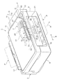
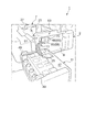
本実施例に係るインクジェットプリンター1は、インクを吐出する記録ヘッド5を備え所定の方向に移動可能なヘッドユニット7と、前記ヘッドユニット7を移動可能に収容し、該プリンター1の外郭すなわちプリンター本体を成すハウジング(以下において「プリンター本体」と言うこともある)2と、前記ハウジング2の側面9の外面に着脱可能に装着されるインク貯留部となるインクタンク11と、前記インクタンク11と前記ヘッドユニット7に両端が接続され、前記インクタンク11内のインクを前記記録ヘッド5へと導く、可撓性を有するインクチューブであって、前記ヘッドユニット7の前記移動に伴って追従変形する変形可動部3を有するインクチューブ13とを備えている。
インクチューブ13は、上記した通り両端が前記インクタンク11と前記ヘッドユニット7に接続されているが、該インクチューブ13は前記インクタンク11と前記ヘッドユニット7との間の部分が、繋ぎ目のない連続した単一チューブに限定されず、複数本を連結して単一の一連のチューブにしたものであってもよい。
An
As described above, both ends of the
また、図示実施例のインクジェットプリンター1は、ハウジング2の上方にスキャナー15を搭載した複合型のインクジェットプリンターである。
このインクジェットプリンター1は、上部に前述したスキャナー15を開閉自在に配置すると共に、該スキャナー15の後部に被記録材(以下、「用紙」ともいう)Pを給紙するための幅方向Bに延びる給紙口17が設けられている。
The
The
また、プリンター本体2の前面パネルの一部を矩形状に開口して、記録実行後の用紙Pを当該プリンター1の前側に排紙するための幅方向Bに延びる排紙口19が設けられている。
また、前記排紙口19の上方には操作パネル21が設けられており、インクジェットプリンター1の各種の操作がこの操作パネル21を使用することによって実行できるように構成されている。
A part of the front panel of the printer
An
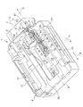
プリンター本体2の内部には、用紙Pの被記録面にインクを吐出して記録を実行するための記録ヘッド5を含む記録実行系の諸部材と、前記給紙口17から給紙された用紙Pを前記記録ヘッド5の下方の記録実行領域23に導いて前記排紙口19から外部に排紙させる図示しない搬送系の諸部材と、前記記録ヘッド5に各色、例えばシアン(C)、マゼンタ(M)、イエロー(Y)、ブラック(K)のインクを供給するためのインクチューブ13を含むインク供給系の諸部材の一部が配設されている。
Inside the printer
記録実行系の諸部材としては、前記各色のインクを個別に吐出するノズル開口を各別に備えた記録ヘッド5と、該記録ヘッド5を下面に搭載して用紙Pの搬送方向Aと交差する幅方向Bを走査方向としてホームポジションとリターンポジションとの間で往復移動するヘッドユニット本体25とを備えるヘッドユニット7と、該ヘッドユニット7を幅方向Bに沿って往復移動させるための図示しないガイド機構及び駆動機構とが設けられている。
The various members of the recording execution system include a
搬送系の諸部材としては、図示は省略するが、給紙口17に挿入された用紙Pを一枚ずつ自動的に搬送経路に導くための自動給紙装置と、搬送経路に導かれた用紙Pを挟持して記録実行領域23に向けて当該用紙Pを搬送する一対のニップローラーによって構成される搬送用ローラーと、記録が実行された用紙Pを排紙口19に向けて搬送し外部に排紙するための同じく一対のニップローラーによって構成される排出用ローラーとを備えることによって構成されている。
Although not shown in the drawing, the various members of the transport system are an automatic paper feeder for automatically guiding the paper P inserted into the
インク供給系の諸部材としては、前記ヘッドユニット7に装着され、前記記録ヘッド5に前述した各色のインクを供給するためのカートリッジ式のアダプター27と、該アダプター27に一端が接続され、他端がハウジング2の一例として図3中、右側の側面9の外側に装着されているインクタンク11の接続部29(図3)に接続されている一例として4本のインクチューブ13C、13M、13Y、13Kと、該4本のインクチューブ13C、13M、13Y、13Kに各色のインクを供給するための着脱可能なインクタンク11とが設けられている。
The various members of the ink supply system are attached to the
尚、前記アダプター27に一端が接続されているインクチューブ13は、変形可動部3のU字反転部31において下方にU字反転した後、排紙口19の上方においてプリンター本体2内で水平に支持されている支持部材33の上面を幅方向Bに沿わせて前記右側の壁面9に向けて延設されている。
また、前記インクチューブ13の第1延設部13aの一例として中央より幾分右側の位置には、前記インクチューブ13のU字反転の可動側端部(起点)35となるチューブ支持板35(可動側端部と同じ符号35を用いる)が上方から宛がわれて固定ネジ37によって前記支持部材33上に固定されている。
The
Further, as an example of the first extending
また、前記インクチューブ13の第1延設部13aの終端には、継手39が取り付けられており、該継手39の内方に突出しているプラグ41に前記インクチューブ13の第1延設部13aの終端が嵌め込まれている。
前記継手39には外方に突出しており、前記プラグ41と連通している他のプラグ43が設けられており、該プラグ43にインクチューブ13の第2延設部13bの一端が嵌め込まれ、軌道修正部45によってインクタンク11の接続部29側に幾分軌道が修正された後、当該インクチューブ13の第2延設部13bは、前記プリンター本体2の側面9から外部に延出されている。
A joint 39 is attached to the end of the first extending
The joint 39 protrudes outward and is provided with another
また、前記プリンター本体2の側面9の上部には、前述したインクタンク11の装着面47の上部コーナー部に設けられている係合フック49と係合する係合穴51が設けられている。
そして、前記プリンター本体2の側面9の部分を利用して前記インクタンク11との間に以下、詳述する本発明に係るインクチューブ13のチューブ収容部67が設けられている。
図において、符号77は前記ヘッドユニット7に接続され、該ヘッドユニット7に記録実行のためのデータ信号を送る、可撓性を有するデータ線である。また、符号78は、ハウジング2の開口部である。
Further, an
A
In the figure,
[実施例](図4−図11参照)
本実施例に係るインクジェットプリンター1は、前記ハウジング2の前記側面9に設けられ、前記インクチューブ13の前記インクタンク11側の部分を該ハウジング2の外部に出すチューブ用貫通部53を備えている。そして、前記インクチューブ13の前記チューブ用貫通部53から外部に出ている部分を、前記インクタンク11の前記装着状態において収容するチューブ収容部67(図2)を備えている。該チューブ収容部67は内部にインクチューブを収容するためのスペースを有している。
前記チューブ用貫通部53とチューブ収容部67は、インクチューブ13の延設経路としては連続してつながる構造である。従って、該チューブ用貫通部53とチューブ収容部67との間に境界位置が物理的に存在していない。
[Example] (see FIGS. 4 to 11)
The
The
これにより、インクチューブ13のハウジング2の外側に延出されている部分は、露呈状態ではなく当該チューブ収容部67内に収容された状態となる。従って、ユーザーがインクチューブ13のハウジング2の外側に延出されている部分に不用意に触れる虞が低減され、使い勝手が改善される。
As a result, the portion of the
本実施例では、前記チューブ収容部67は、前記ハウジング2に装着された状態の前記インクタンク11の外面である前記装着面47と前記ハウジング2の側面9の外面との間に設けられている。即ち、前記インクタンク11の外面と前記ハウジング2の側面9の外面(プリンター本体の外側)との間のスペースを活用して、当該スペースにチューブ収容部67が設けられている。
In the present embodiment, the
前記スペースを利用することにより、チューブ収容部67の設置場所をインクジェットプリンター1が大型化することなく容易に確保することができる。また、外観としてはインクタンク11がハウジング2に装着された状態のインクジェットプリンターが見えるだけで、当該チューブ収容部67の場所は外部から目立たないので、当該インクジェットプリンター1の外観の質的低下を抑制することができる。
By using the space, the installation place of the
尚、チューブ収容部67の設置場所は、上記のスペースに限定されない。前記実施例の変形例として、例えば、インクタンク11の前記ハウジング2と対向する面(装着面47)ではなく、対向しない側面に収容室を設け、該収容室をチューブ収容部67とすることも可能である。
In addition, the installation place of the
前記インクタンク11は、前記ハウジング2に装着された状態において、前記インクチューブ13との接続部29が以下の位置になるように構成されている。即ち、前記接続部29は、前記インクチューブ13の前記変形可動部3を成す第1延設部13aを延設方向Dに延設させて前記ハウジング2の外側にまで延長したと想定した場合に占める領域に対して平面視でずれて位置している。
即ち、前記接続部29は、インクチューブ13の変形可動部3を成す第1延設部13aの位置に対して平面視で当該インクジェットプリンター1の後方側にずれて配置されている。
The
In other words, the connecting
前記「ずれ」によって、チューブ収容部67内に収容されるインクチューブ13の全長を前記ずれの分だけ長くすることができる。これにより、該チューブ収容部67をハウジング2から外して例えばインクの補給作業を行う場合等において作業がし易くなる。
Due to the “deviation”, the total length of the
尚、前記「ずれ」を設けずに、前記想定した場合に占める領域の下方に接続部29を位置させる構造であってもよい。
In addition, the structure which positions the
前記接続部29は、前記インクタンク11の下部に位置している。そして、前記インクチューブ13は、前記ハウジング2の前記側面9の内面に沿って上方に延設され、前記チューブ用貫通部53を通って外部に出て、下方に延びて前記接続部29に接続されている。これにより、インクチューブ13はチューブ用貫通部53を上下方向に対して略逆U字形状を成して内側から外側に出る構造となる。即ち、インクチューブ13は前記ハウジング2の側面9に対して内面及び外面の両方において沿う状態で延設される。
従って、インクチューブ13の前記逆U字形状部分はハウジング2の側面9を挟む形状となって存在するので、該ハウジング2の前記側面9がインクチューブ13の支持部材或いは芯材として機能し、当該インクチューブ13の安定した配設状態を実現することができる。
The connecting
Accordingly, since the inverted U-shaped portion of the
尚、インクチューブ13は、前記逆U字形状を取らずにハウジング2の内側から外側に略直線的に出て、それから下方に延びて前記接続部と接続される構成とすることも可能である。
The
本実施例において、前記チューブ用貫通部53は、平面視で、インクチューブ13の変形可動部3側に前記延設部13aの前記想定した場合に占める領域と前記接続部29との間に位置する。ここでは、インクチューブ13の変形可動部3側に前記延設部13aの「前記想定した場合に占める領域」と「チューブ用貫通部53」と「接続部29」の三者は、各境界でオーバーラップした配置で設けられている。
この構成により、インクチューブ13の配設がし易いと共に、該インクチューブ13に無理な姿勢を取らせずに済む効果が得られる。
In the present embodiment, the
With this configuration, it is easy to dispose the
また、前記インクチューブ13は、前記変形可動部3の可動側端部35から前記チューブ用貫通部53側に延設される部分である第2延設部13bが、平面視で前記変形可動部3を成す第1延設部13aの延設方向Dに延設させた後、前記軌道修正部45において前記チューブ用貫通部53に対応する位置に軌道修正されて延設されている。
該軌道修正部45は、本実施例では、インクチューブ13の配設経路が下方の凸曲面を成すようにその形状が構成されている。これにより、インクチューブ13に引っ張り力が作用した際に、その引っ張り力の伝達を当該凸曲面の軌道修正部45の存在によって遮断し、他に伝達する虞を低減している。
In addition, the
In this embodiment, the
本実施例によれば、前記軌道修正によってチューブ用貫通部53をインクチューブ13が正面からストレートに通って外部に出ることが可能になる。従って、該チューブ貫通部53に対してインクチューブ13の配設がし易いと共に、該インクチューブ13に無理な姿勢をとらせないで済む。
According to the present embodiment, the trajectory correction allows the
本実施例では、前記チューブ用貫通部53は、前記インクチューブ13の該チューブ用貫通部53を通る部分を前記接続部29の方向に誘導するガイド構造部61を備えている。該ガイド構造部61は、具体的には一例として以下のように構成されている。
該ガイド構造部61は、前記チューブ用貫通部53の下縁54を成して前記インクチューブ13を前記ハウジング2の内側から外側に向かって斜め上方に誘導する上方誘導部63と、前記チューブ用貫通部53の前記接続部29側の側縁68を成して前記インクチューブ13を前記ハウジング2の内側から外側であって且つ平面視で前記接続部29の在る方向に向かって斜め側方(誘導方向C)に誘導する側方誘導部65とを備えている。
In the present embodiment, the
The
前記上方誘導部63は、前記チューブ用貫通部53の前記下縁54を成す部材としてハウジング2の前記側面9の外面からハウジング2の外側に向けて上り傾斜で突出した板状の部材によって形成されている。この板状部材の上面が前記インクチューブ13を斜め上方に誘導する上方誘導面64である。
また、前記側方誘導部65は、同じくハウジング2の前記側面9の外面からハウジング2の外側に向けて突出する一例として平面視台形状をした凸状部75によって形成されている。この凸状部75の一つの面が開き傾斜に形成されて前記チューブ用貫通部53の前記側縁68を成し、且つ前記インクチューブ13を斜め側方に誘導する側方誘導面66である。
The
Further, the
ガイド構造部61によって、以下の効果が得られる。即ち、ガイド構造部61がインクチューブ13の該チューブ用貫通部53を通る部分を前記接続部29の方向に誘導する。従って、インクタンク11をハウジング2から外した後、再び装着する際に、インクチューブ13は前記ガイド構造部61による誘導作用を受けてチューブ収容部67に収容される。すなわち、ユーザーは、インクタンク11をハウジング2の所定箇所に装着するだけで、インクチューブ13は前記上方誘導部63及び側方誘導部65の誘導作用によって前記チューブ収容部2内に自動的に収容される。
これにより、インクチューブ13をチューブ収容部67内に押し込むような面倒な作業を減らすことができる。また、チューブ用貫通部53からチューブ収容部67の領域においてインクチューブ13が折れ曲がったり周囲の構造部材に挟み込まれたりする虞を低減することができる。
The
Thereby, the troublesome work of pushing the
尚、前記ガイド構造部61の具体的構造は、上記実施例の「上方誘導部63(チューブ用貫通部53の下縁54を成してインクチューブを斜め上方に誘導)」と「側方誘導部65(チューブ用貫通部53の側縁68を成してインクチューブを斜め側方に誘導)」による構造に限定されない。
ユーザーがインクタンク11をハウジング2の所定箇所に装着するだけで、インクチューブ13がその誘導作用によって前記チューブ収容部2内に自動的に収容される構造であれば種々の変形が可能である。
The specific structure of the
Various modifications are possible as long as the
前記ガイド構造部61は、本実施例では更に前記チューブ用貫通部53の前記側方誘導部65と反対側に設けられ、前記インクチューブ13が前記側方誘導部65の誘導方向Cと反対側に移動することを規制する第1移動規制部57を備えている。更に、前記上方誘導部63と前記側方誘導部65が作るコーナー部に設けられ、該コーナー部に前記インクチューブ13が移動することを規制する第2移動規制部59を備えている。
In this embodiment, the
ここで、第1移動規制部57は、前記チューブ用貫通部53の前記側縁68と反対側の側縁10に設けられ、複数の凸状リブ58と移動規制面56とを備えている。
また、第2移動規制部59はブロック状の凸部60で形成されている。
Here, the first
The second
第1移動規制部57と第2移動規制部59を設けたことにより、チューブ用貫通部53からチューブ収容部67の領域においてインクチューブ13が折れ曲がったり周囲の構造部材に挟み込まれたりする虞を一層低減することができる。
By providing the first
本実施例では前記チューブ用貫通部53から外側に出されたインクチューブ13の延出方向である誘導方向Cは、図3に示すように前記プリンター本体2内でのインクチューブ13の延設方向Dに対して前記チューブ収容部67側に偏倚した傾斜した方向に設定されている。
また、前記チューブ用貫通部53は、プリンター本体2の前記側面9の上部の一部を上方から所定深さ切り欠いた凹部69と、該凹部69に対して上方から係脱可能に係合する凹部カバー71を備えている。
In this embodiment, the guiding direction C, which is the extending direction of the
The
具体的には、前記凹部69は、図10に示すように、下部にチューブ用貫通部53として機能する矩形状の幅広の第1凹部69Aが形成されており、該第1凹部69Aの上方に矩形状の幅狭の第2凹部69Bが連接されたL字形をした凹部によって形成されている。
また、前記凹部カバー71は、前記凹部69の上面の開口を閉塞する一例として平面視矩形状の天板部71Aと、該天板部71Aの下面から下方に向けて突出する矩形板状の係合板部71Bと、当該凹部カバー71をプリンター本体2に取り付けるための鉤状の2つの係合爪部71C、71Cとを備えている。
Specifically, as shown in FIG. 10, the
The
一方、前記凹部69が形成されているプリンター本体2の前記側面9には、前記係合爪部71C、71Cに係合する2つの係合受部73、73が設けられている。
そして、前記凹部カバー71を前記凹部69に取り付けた状態では、該凹部カバー71の天板部71Aがプリンター本体2の前記側面9の上面とほぼ面一になり、図10に示すように、凹部カバー71の係合板部71Bが前記凹部69の第2凹部69Bに嵌まることで矩形状のチューブ用貫通部53が構成されている。
On the other hand, on the
When the
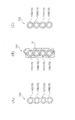
また、本発明において使用できるインクチューブ13は、使用するインクの数に対応した複数本のインクチューブ、例えば13C、13M、13Y、13Kが一体に構成された図11(A)に示すような多連チューブ130であってもよいし、使用するインクの数に対応した複数本のインクチューブ、例えば13C、13M、13Y、13Kが拘束具14によって一体化された図11(B)に示すような拘束チューブ131であってもよい。
また、本発明において使用できるインクチューブ13は、使用するインクの数に対応して複数本のインクチューブ、例えば13C、13M、13Y、13Kが拘束されずに存在する図11(C)に示すような非拘束チューブ132であってもよい。
更に、これら3種類のインクチューブ130、131、132を適宜組み合わせたインクチューブであってもよい。
In addition, the
Further, the
Furthermore, an ink tube in which these three types of
次に、上記のように構成される本実施例に係るインクジェットプリンター1において、その作用をインクタンク11の着脱の手順に従って説明する。
Next, the operation of the
(1)インクタンクの装着状態
着脱自在なインクタンク11がハウジング2の側面9の外面に装着された状態においては、インクチューブ13のチューブ用貫通部53からハウジング2の外側に出ている部分は、チューブ収容部67によって収容される。従って、インクチューブ13のハウジング2の外部に延出されている部分は、露呈状態ではなくチューブ収容部67内に収容された状態となり、ユーザーが不用意に触れる虞が低減され、使い勝手が改善されている。
(1) Ink Tank Mounted State When the
(2)インクタンクの取り外し
インクタンク11のインクの残量が少なくなってきたら、インクタンク11をプリンター本体2の側面9から外してインクの補充を行う。
この場合、インクタンク11を上方に持ち上げてインクタンク11の係合フック49をプリンター本体2の側面9に形成されている係合穴51から引き抜いて両者の係合を解除する。
この場合、チューブ収容部67内に収容されていたインクチューブ13の長さの範囲でインクタンク11を移動したり、倒すことができ、インクの補充を行い易い姿勢にしてインクを補充する。
(2) Removal of ink tank When the remaining amount of ink in the
In this case, the
In this case, the
(3)インクタンクの装着
インクタンク11にインクを補充したら、インクタンク11を持って、インクタンク11の係合フック49をプリンター本体2の側面9に形成されている係合穴51に合わせて両者を係合状態にすればインクタンク11の装着が完了する。
この際、前記チューブ用貫通部53からハウジング2の外側に延出されたインクチューブ13は、ガイド構造部61がインクチューブ13の該チューブ用貫通部53を通る部分を前記接続部29の方向Cに誘導するので、インクタンク11をハウジング2の側面9に装着する際に、インクチューブ13は前記ガイド構造部61による誘導作用を受けてチューブ収容部67に収容される。
すなわち、ユーザーはインクタンク11をハウジング2に装着するだけでインクチューブ13は前記誘導作用によって前記チューブ収容部67内に自動的に収容される。
従って、インクチューブ13をチューブ収容部67内に押し込むような面倒な作業を減らすことができる。また、チューブ用貫通部53からチューブ収容部67の領域においてインクチューブ13が折れ曲がったり周囲の構造部材に挟み込まれたりする虞を低減することができる。
(3) Installation of ink tank After the
At this time, the
That is, the user simply installs the
Therefore, the troublesome work of pushing the
[緩衝部]
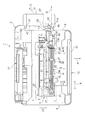
図1〜図3及び図13に示したように、本実施例に係るインクジェットプリンター1は、インクを吐出する記録ヘッド5を備え所定の方向に移動可能なヘッドユニット7と、インク収容部であるインクタンク11と前記ヘッドユニット7に両端が接続され、前記インクタンク11内のインクを前記記録ヘッド5へと導く、可撓性を有するインクチューブ13を備えている。該インクチューブ13は、前記ヘッドユニット7の前記移動に伴ってU字反転部31を介して追従変形する変形可動部3を有する。
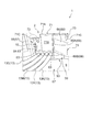
更に、前記変形可動部3の変形拡大側に存在する拡大側構成部材であるスキャナー15の底面部79(図13)と、前記スキャナー15の底面部79と前記変形可動部3を成すインクチューブ13との間に緩衝部90が存在し、該緩衝部90は前記変形拡大するインクチューブ13が接触するようになっている。
[Buffer part]
As shown in FIGS. 1 to 3 and 13, the
Furthermore, the bottom surface portion 79 (FIG. 13) of the
本実施例では、前記インクチューブ13の前記変形可動部3の変形拡大方向は上方向である。また、前記スキャナー15は、前記底面部79に前記ヘッドユニット7の移動方向に延在する突状部80を備え、前記インクチューブ13の前記変形可動部3は、前記ヘッドユニット7の移動方向に交差する前後方向において、前記ヘッドユニット7と前記閉じた状態における突状部80との間に位置する。
また、前記突状部80は、前記スキャナー15が閉じた状態において、該スキャナー15の下側に位置するプリンター本体2の上面より該プリンター本体2内に侵入して位置する構成である。更に、前記突状部80は、前記スキャナー15が閉じた状態において、前記ヘッドユニット7の上面よりも下側に位置するように構成されている。
In the present embodiment, the deformation expansion direction of the deformation movable portion 3 of the
The protruding
図13において、符号86は給送ローラー、符号87は搬送用ローラー、符号88は排出用ローラー、符号89は用紙の支持部、符号76はヘッドユニット7のガイド軸である。また、符号81はセンサー移動機構のモーター、符号82はセンサーユニットを搭載したセンサーキャリッジをスライド自在に支持するガイド軸を示す。また符号84はスキャナー15の回動支点となるスキャナー回動軸、符号85はスキャナー15の原稿カバー83の回動支点となるカバー軸である。
また本実施例では、前記突状部80と前記ヘッドユニット7の上部とは、図13に示したように、高さ方向においてオーバーラップしている構成である。
In FIG. 13,
In the present embodiment, the
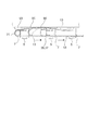
再び緩衝部90について説明する。
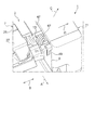
図13及び図14(A)に示したように、前記緩衝部90は、前記ヘッドユニット7の移動方向Bに沿う3本の長尺なリブ90(緩衝部と同じ符号を用いる)として形成されている。該リブ90は、前記スキャナー15の底面部79に保持部91を介して前記底面部79と一体に設けられている。リブ90は少なくとも1本あればよいが接触の安定性の点から2本以上が好ましい。
図14(A)では、一方の移動端においては(図の左の位置)、インクチューブ13は緩衝部90に接触していない構造が示されている。この構造でもよいが、該リブ90を、前記ヘッドユニット7が一方の移動端から他方の移動端まで移動する際に、前記インクチューブ7と接触状態が常に維持される構成とするのが好ましい。
The
As shown in FIGS. 13 and 14A, the
FIG. 14A shows a structure in which the
本実施例では、図14(B)に示したように、前記インクチューブ13はシート状のカバー92を備え、該カバー92が前記緩衝部90と接触するようになっている。
これにより、カバー92が前記リブ等の緩衝材90と接触するので、インクチューブ13の磨耗劣化を抑制することができる。
In this embodiment, as shown in FIG. 14B, the
As a result, the
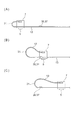
次に上記実施例の緩衝部の作用を図12及び図14を用いて説明する。
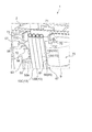
比較例として、緩衝部90を有していない構造の図12について説明する。同図(A)からヘッドユニット7が図の左に向って移動を開始すると、インクチューブ13の変形可動部3のU字反転部31が、その弾性材としての弾性力によって次第に上方に大きくなるように変形拡大する。同図(B)が大きく変形拡大した状態を示している。更にヘッドユニット7が移動すると同図(C)の状態になる。同図(C)は上方に変形拡大できる部分の全長が最も長くなった状態であるので、その変形可動部3の自重によって変形拡大量が同図(B)より小さくなっている。
Next, the operation of the buffer portion of the above embodiment will be described with reference to FIGS.
As a comparative example, FIG. 12 having a structure not including the
図12から明らかなように、ヘッドユニット7の移動に伴うインクチューブ13の変形可動部3の変形拡大量が大きいので、その上方の近くにスキャナー15の底面79部等の拡大側構成部材が存在すると、それに衝突して騒音を発生する虞がある。
As is clear from FIG. 12, since the deformation and enlargement amount of the deformation movable portion 3 of the
図14に示したように、本実施例では、緩衝部90として前記リブ90が設けられているので、ヘッドユニット7の移動に伴う変形可動部3の変形カ拡大は小さく押さえられる。これにより、スキャナー15の底面部79の衝突することを当該リブが防止し、騒音の発生を抑制することができる。
As shown in FIG. 14, in this embodiment, the
以上説明したように、本実施例によれば、スキャナー15の底面部79と前記変形可動部3を成すインクチューブ13との間に緩衝部90が存在し、該緩衝部90に前記変形拡大するインクチューブ13が接触する。従って、インクチューブ13が前記スキャナー15の底面部79に直接衝突しないで緩衝部90に接触するので、該緩衝部90の緩衝作用によって騒音の発生を低減することができる。緩衝部90に接触する段階のインクチューブ13の変形拡大量は未だ小さいので、その分衝撃も小さくなり、騒音を抑制することができる。
As described above, according to the present embodiment, the
また、緩衝部90は前記ヘッドユニット7の移動方向に沿う長尺なリブ90であるので、接触するインクチューブ13との接触面積が小さくなり、これにより前記騒音を低減することができる。また、前記変形可動部3を成すインクチューブ13との接触位置がヘッドユニット7の移動に伴って移動するが、その移動は長尺なリブ90上を前記接触位置がスライド移動することになるので、滑らかであり、その点においても騒音低減は効果的である。
Moreover, since the
また、インクチューブ13の変形可動部3が、その変形可動の全工程において前記リブ90と接触するように構成すれば、従来のような「衝突現象」が起こらない。また、前記全工程において当該リブ90によってその変形拡大を規制される。従って、一層効果的に前記騒音を低減することができる。
Further, if the deformable movable portion 3 of the
[緩衝部の他の実施例]
図15に示したように、本実施例では、前記リブ90は、前記変形可動部3の変形の大きい領域と小さい領域に対して接触圧力の差が小さくなるようにリブ高さを変化して形成されている。即ち、リブ高さは滑らかな凹凸曲面に形成されている。
[Other Embodiments of Buffer]
As shown in FIG. 15, in this embodiment, the
インクチューブ13の前記変形可動部3の変形拡大量は、前記ヘッドユニット7の移動位置に対して一定ではない。即ちリブ90とインクチューブ13との接触部の接触圧力は一定では無く、大小の差がある。
本実施例によれば、リブ高さが前記接触圧力の差を小さくするように形成されているので、ほぼ一様な接触圧力の状態で変形拡大させることができる。これにより、騒音の低減を図りつつ、ヘッドユニット7の搬送負荷の変動が小さくなるので、該ヘッドユニット7の移動が安定し、記録品質を向上することができる。
The deformation expansion amount of the deformation movable portion 3 of the
According to the present embodiment, since the rib height is formed so as to reduce the difference in the contact pressure, it can be deformed and enlarged in a substantially uniform contact pressure state. As a result, the fluctuation in the transport load of the
[他の実施例]
本発明に係る記録装置1は、以上述べたような構成を有することを基本とするものであるが、本願発明の要旨を逸脱しない範囲内の部分的構成の変更や省略等を行うことは勿論可能である。
[Other embodiments]
The
他の実施例として、前記インクチューブ13の前記変形可動部3の変形拡大方向は上下方向に交差する前後方向であり、前記拡大側構成部材は、前記前側又は後側に位置して前記変形可動部3と対向するフレーム等の対向部材であってもよい。本発明は、このように複合機ではない記録装置においても、その適用によって、騒音発生の虞を低減することができる。
As another embodiment, the deformation expansion direction of the deformation movable portion 3 of the
また緩衝部90はリブに代えて、前記拡大側構成部材に設けられ、前記ヘッドユニット7の移動方向に沿って点在する突起郡であってもよい。
また緩衝部はスポンジなどのクッション材であってもよい。
In addition, the
The buffer portion may be a cushion material such as a sponge.
また、インク収容部はインクタンクでなく、例えばインクカートリッジであってもよい。インクタンクをハウジングに装着しないで単にハウジングの外側に置く構造でもよい。 Further, the ink container may not be an ink tank but may be an ink cartridge, for example. A structure in which the ink tank is not attached to the housing but simply placed outside the housing may be employed.
また例えば、ハウジング2の側面9に形成したチューブ用貫通部53は、前記の実施例のように凹部69と凹部カバー71によって構成することに代えて、前記側面9に形成した穴部やスリット等を利用して構成することも可能である。
この他、インクタンク11の位置は、図3に示すようにプリンター本体2の右側の側面9の外側に限らず、プリンター本体2の左側の側面9の外側に設定したり、左右の側面9の外側に振り分けて設定することが可能である。
Further, for example, the
In addition, the position of the
1 インクジェットプリンター(記録装置) 、2 ハウジング(プリンター本体)、
3 変形可動部、5 記録ヘッド、7 ヘッドユニット、9 側面、10 側縁、
11 インクタンク、13 インクチューブ、13a 第1延設部、
13b 第2延設部、14 拘束具、15 スキャナー、17 給紙口、
19 排紙口、21 操作パネル、23 記録実行領域、
25 ヘッドユニット本体、27 アダプター、29 接続部、31 U字反転部、
33 支持部材、35 可動側端部(チューブ支持板)、37 固定ネジ、
39 継手、41 プラグ、43 プラグ、45 軌道修正部、47 装着面、
49 係合フック、51 係合穴、53 チューブ用貫通部、54 下縁、
56 移動規制面、57 第1移動規制部、58 凸状リブ、59 第2移動規制部、
60 ブロック状の凸部、61 ガイド構造部、63 上方誘導部、
64 上方誘導面、65 側方誘導部、66 側方誘導面、67 チューブ収容部、
68 側縁、69 凹部、69A 第1凹部、69B 第2凹部、71 凹部カバー、
71A 天板部、71B 係合板部、71C 係合爪部、73 係合受部、
75 凸状部、80 突状部、81 モーター、82 ガイド軸、83 原稿カバー、
84 スキャナー回動軸、85 カバー軸、86 給送ローラー、
87 搬送用ローラー、88 排出用ローラー、89 支持部、90 緩衝部、
91 保持部、130 多連チューブ、131 拘束チューブ、
132 非拘束チューブ、P 用紙(被記録材)、A 搬送方向、B 幅方向、
C 誘導方向、D 延設方向
1 inkjet printer (recording device), 2 housing (printer body),
3 Deformation movable part, 5 Recording head, 7 Head unit, 9 Side surface, 10 Side edge,
11 Ink tank, 13 Ink tube, 13a First extending portion,
13b 2nd extension part, 14 restraint tool, 15 scanner, 17 paper feed port,
19 discharge port, 21 operation panel, 23 recording execution area,
25 head unit main body, 27 adapter, 29 connection part, 31 U-shaped inversion part,
33 support member, 35 movable side end (tube support plate), 37 fixing screw,
39 Joint, 41 plug, 43 plug, 45 track correction part, 47 mounting surface,
49 engagement hook, 51 engagement hole, 53 tube penetration, 54 lower edge,
56 movement restriction surfaces, 57 first movement restriction portions, 58 convex ribs, 59 second movement restriction portions,
60 block-shaped convex part, 61 guide structure part, 63 upper guide part,
64 upper guide surface, 65 side guide portion, 66 side guide surface, 67 tube housing portion,
68 side edge, 69 recess, 69A first recess, 69B second recess, 71 recess cover,
71A Top plate part, 71B Engagement plate part, 71C Engagement claw part, 73 Engagement receiving part,
75 Projection, 80 Projection, 81 Motor, 82 Guide shaft, 83 Document cover,
84 Scanner rotation axis, 85 Cover axis, 86 Feed roller,
87 transport roller, 88 discharge roller, 89 support, 90 buffer,
91 holding part, 130 multiple tube, 131 restraint tube,
132 Non-restraint tube, P paper (recording material), A transport direction, B width direction,
C Guide direction, D Extension direction
Claims (10)
インクが収容されたインク収容部から送られるインクを前記記録ヘッドへと導き、前記ヘッドユニットの前記移動に伴ってU字反転部を介して追従変形する変形可動部を有するインクチューブと、
前記変形可動部の変形拡大側に存在する拡大側構成部材と、
前記拡大側構成部材と前記変形可動部を成すインクチューブとの間に存在し、前記変形拡大するインクチューブが接触する緩衝部と、を備える記録装置。 A head unit including a recording head for ejecting ink and movable in a predetermined direction;
An ink tube having a deformable movable part that guides ink sent from an ink containing part containing ink to the recording head and deforms following the movement of the head unit via a U-shaped reversing part;
An enlargement side component existing on the deformation enlargement side of the deformation movable part; and
A recording apparatus comprising: a buffer portion that exists between the enlargement-side component member and the ink tube that forms the deformable movable portion and contacts the ink tube that is deformed and enlarged.
前記インクチューブの前記変形可動部の変形拡大方向は上方向であり、
前記拡大側構成部材は、開閉可能なスキャナーの閉じた状態における底面部である、ことを特徴とする記録装置。 The recording apparatus according to claim 1,
The deformation expansion direction of the deformation movable part of the ink tube is an upward direction,
The recording apparatus according to claim 1, wherein the enlargement-side component member is a bottom surface portion in a closed state of the openable / closable scanner.
前記スキャナーは、前記底面部に前記ヘッドユニットの移動方向に延在する突状部を備え、
前記インクチューブの前記変形可動部は、前記ヘッドユニットの移動方向に交差する方向において、前記ヘッドユニットと前記閉じた状態における突状部との間に位置する、ことを特徴とする記録装置。 The recording apparatus according to claim 2,
The scanner includes a protruding portion extending in the moving direction of the head unit on the bottom surface portion,
The recording apparatus according to claim 1, wherein the deformation movable portion of the ink tube is located between the head unit and the projecting portion in the closed state in a direction intersecting a moving direction of the head unit.
前記突状部は、前記スキャナーが閉じた状態において、該スキャナーの下側に位置するプリンター本体の上面より該プリンター本体内に侵入して位置する、ことを特徴とする記録装置。 The recording apparatus according to claim 3,
The recording apparatus according to claim 1, wherein the protruding portion is positioned so as to enter the printer main body from an upper surface of the printer main body located below the scanner in a state where the scanner is closed.
前記突状部は、前記スキャナーが閉じた状態において、前記ヘッドユニットの上面よりも下側に位置する、ことを特徴とする記録装置。 The recording apparatus according to claim 3,
The recording apparatus according to claim 1, wherein the protrusion is positioned below the upper surface of the head unit in a state where the scanner is closed.
前記インクチューブの前記変形可動部の変形拡大方向は上下方向に交差する方向であり、
前記拡大側構成部材は、前記交差する方向に位置して前記変形可動部と対向する対向部材である、ことを特徴とする記録装置。 The recording apparatus according to claim 1,
The deformation expansion direction of the deformation movable part of the ink tube is a direction intersecting the up and down direction,
The recording apparatus according to claim 1, wherein the enlargement-side component member is a facing member that is positioned in the intersecting direction and faces the deformation movable portion.
前記緩衝部は、前記拡大側構成部材に設けられ、前記ヘッドユニットの移動方向に沿う長尺なリブである、ことを特徴とする記録装置。 The recording apparatus according to any one of claims 1 to 6,
The recording apparatus according to claim 1, wherein the buffer portion is a long rib provided on the enlargement-side component member and extending along a moving direction of the head unit.
前記リブは、前記ヘッドユニットが一方の移動端から他方の移動端まで移動する際に、前記インクチューブと接触状態にある、ことを特徴とする記録装置。 The recording apparatus according to claim 7,
The recording apparatus according to claim 1, wherein the rib is in contact with the ink tube when the head unit moves from one moving end to the other moving end.
前記リブは、前記変形可動部の変形の大きい領域と小さい領域に対して接触圧力の差が小さくなるようにリブ高さを変化して形成されている、ことを特徴とする記録装置。 The recording apparatus according to claim 8,
The recording apparatus according to claim 1, wherein the rib is formed by changing a rib height so that a difference in contact pressure is small between a large deformation area and a small area of the deformation movable portion.
前記インクチューブはシート状のカバーを備え、該カバーが前記緩衝部と接触する、ことを特徴とする記録装置。 In the recording device according to any one of claims 7 to 9,
The recording apparatus, wherein the ink tube includes a sheet-like cover, and the cover is in contact with the buffer portion.
Priority Applications (2)
| Application Number | Priority Date | Filing Date | Title |
|---|---|---|---|
| JP2012031449A JP6083114B2 (en) | 2012-02-16 | 2012-02-16 | Recording device |
| CN 201320072916 CN203267463U (en) | 2012-02-16 | 2013-02-16 | Recording device |
Applications Claiming Priority (1)
| Application Number | Priority Date | Filing Date | Title |
|---|---|---|---|
| JP2012031449A JP6083114B2 (en) | 2012-02-16 | 2012-02-16 | Recording device |
Publications (2)
| Publication Number | Publication Date |
|---|---|
| JP2013166328A true JP2013166328A (en) | 2013-08-29 |
| JP6083114B2 JP6083114B2 (en) | 2017-02-22 |
Family
ID=49177158
Family Applications (1)
| Application Number | Title | Priority Date | Filing Date |
|---|---|---|---|
| JP2012031449A Active JP6083114B2 (en) | 2012-02-16 | 2012-02-16 | Recording device |
Country Status (2)
| Country | Link |
|---|---|
| JP (1) | JP6083114B2 (en) |
| CN (1) | CN203267463U (en) |
Cited By (1)
| Publication number | Priority date | Publication date | Assignee | Title |
|---|---|---|---|---|
| US20220210282A1 (en) * | 2020-12-28 | 2022-06-30 | Canon Kabushiki Kaisha | Image reading and printing apparatus |
Citations (6)
| Publication number | Priority date | Publication date | Assignee | Title |
|---|---|---|---|---|
| JP2001171096A (en) * | 1999-12-17 | 2001-06-26 | Copyer Co Ltd | Ink jet imaging apparatus |
| JP2002019227A (en) * | 2000-07-12 | 2002-01-23 | Seiko Epson Corp | Cable guide member, device cover, recording device |
| JP2003175631A (en) * | 2001-12-10 | 2003-06-24 | Brother Ind Ltd | Inkjet printer |
| JP2006082281A (en) * | 2004-09-14 | 2006-03-30 | Mutoh Ind Ltd | Drawing device |
| JP2009160742A (en) * | 2007-12-28 | 2009-07-23 | Brother Ind Ltd | Scanning apparatus and image recording apparatus |
| JP2011156670A (en) * | 2010-01-29 | 2011-08-18 | Seiko Epson Corp | Recording apparatus |
-
2012
- 2012-02-16 JP JP2012031449A patent/JP6083114B2/en active Active
-
2013
- 2013-02-16 CN CN 201320072916 patent/CN203267463U/en not_active Expired - Fee Related
Patent Citations (6)
| Publication number | Priority date | Publication date | Assignee | Title |
|---|---|---|---|---|
| JP2001171096A (en) * | 1999-12-17 | 2001-06-26 | Copyer Co Ltd | Ink jet imaging apparatus |
| JP2002019227A (en) * | 2000-07-12 | 2002-01-23 | Seiko Epson Corp | Cable guide member, device cover, recording device |
| JP2003175631A (en) * | 2001-12-10 | 2003-06-24 | Brother Ind Ltd | Inkjet printer |
| JP2006082281A (en) * | 2004-09-14 | 2006-03-30 | Mutoh Ind Ltd | Drawing device |
| JP2009160742A (en) * | 2007-12-28 | 2009-07-23 | Brother Ind Ltd | Scanning apparatus and image recording apparatus |
| JP2011156670A (en) * | 2010-01-29 | 2011-08-18 | Seiko Epson Corp | Recording apparatus |
Cited By (3)
| Publication number | Priority date | Publication date | Assignee | Title |
|---|---|---|---|---|
| US20220210282A1 (en) * | 2020-12-28 | 2022-06-30 | Canon Kabushiki Kaisha | Image reading and printing apparatus |
| US12113943B2 (en) | 2020-12-28 | 2024-10-08 | Canon Kabushiki Kaisha | Image reading and printing apparatus |
| JP7599943B2 (en) | 2020-12-28 | 2024-12-16 | キヤノン株式会社 | Recording device |
Also Published As
| Publication number | Publication date |
|---|---|
| CN203267463U (en) | 2013-11-06 |
| JP6083114B2 (en) | 2017-02-22 |
Similar Documents
| Publication | Publication Date | Title |
|---|---|---|
| CN103991287B (en) | Ink-jet recording apparatus | |
| JP6183430B2 (en) | Inkjet recording device | |
| JP6606968B2 (en) | Conveying apparatus and image recording apparatus | |
| US9376284B2 (en) | Medium receiving cassette and recording apparatus | |
| CN103129174A (en) | Image forming device | |
| US9701497B2 (en) | Sheet tray | |
| JP6083115B2 (en) | Recording device | |
| JP5948929B2 (en) | Recording device | |
| JP6083114B2 (en) | Recording device | |
| US7168799B2 (en) | Release mechanism for facilitating supply cartridge installation and removal | |
| JP5041042B2 (en) | Image forming apparatus | |
| JP2014169188A (en) | Tray and image recording device | |
| JP5360426B2 (en) | Tray and image recording apparatus | |
| JP7694231B2 (en) | Recording device | |
| JP6090410B2 (en) | Tray and image recording apparatus | |
| EP3608117B1 (en) | Inkjet printing apparatus | |
| JP5569170B2 (en) | Tray and image recording apparatus | |
| JP7021515B2 (en) | Liquid sprayer | |
| JP6217285B2 (en) | Image forming apparatus | |
| JP2025012725A (en) | Cartridge, cartridge set, and recording device | |
| JP2007290801A (en) | Inkjet printer and image forming device | |
| JP2007119232A (en) | Image reading apparatus and image forming apparatus | |
| JP2016055612A (en) | Liquid ejection device | |
| JP2008068424A (en) | Carriage, recording device, liquid ejecting device | |
| JP2007090897A (en) | Carriage and recording apparatus provided with the carriage |
Legal Events
| Date | Code | Title | Description |
|---|---|---|---|
| RD04 | Notification of resignation of power of attorney |
Free format text: JAPANESE INTERMEDIATE CODE: A7424 Effective date: 20150107 |
|
| A621 | Written request for application examination |
Free format text: JAPANESE INTERMEDIATE CODE: A621 Effective date: 20150203 |
|
| A977 | Report on retrieval |
Free format text: JAPANESE INTERMEDIATE CODE: A971007 Effective date: 20151118 |
|
| A131 | Notification of reasons for refusal |
Free format text: JAPANESE INTERMEDIATE CODE: A131 Effective date: 20151124 |
|
| A521 | Written amendment |
Free format text: JAPANESE INTERMEDIATE CODE: A523 Effective date: 20160115 |
|
| A131 | Notification of reasons for refusal |
Free format text: JAPANESE INTERMEDIATE CODE: A131 Effective date: 20160607 |
|
| RD04 | Notification of resignation of power of attorney |
Free format text: JAPANESE INTERMEDIATE CODE: A7424 Effective date: 20160609 |
|
| RD03 | Notification of appointment of power of attorney |
Free format text: JAPANESE INTERMEDIATE CODE: A7423 Effective date: 20160617 |
|
| A521 | Written amendment |
Free format text: JAPANESE INTERMEDIATE CODE: A523 Effective date: 20160727 |
|
| TRDD | Decision of grant or rejection written | ||
| A01 | Written decision to grant a patent or to grant a registration (utility model) |
Free format text: JAPANESE INTERMEDIATE CODE: A01 Effective date: 20161227 |
|
| A61 | First payment of annual fees (during grant procedure) |
Free format text: JAPANESE INTERMEDIATE CODE: A61 Effective date: 20170109 |
|
| R150 | Certificate of patent or registration of utility model |
Ref document number: 6083114 Country of ref document: JP Free format text: JAPANESE INTERMEDIATE CODE: R150 |