JP2013166319A - Paperweight - Google Patents
Paperweight Download PDFInfo
- Publication number
- JP2013166319A JP2013166319A JP2012031414A JP2012031414A JP2013166319A JP 2013166319 A JP2013166319 A JP 2013166319A JP 2012031414 A JP2012031414 A JP 2012031414A JP 2012031414 A JP2012031414 A JP 2012031414A JP 2013166319 A JP2013166319 A JP 2013166319A
- Authority
- JP
- Japan
- Prior art keywords
- piece
- divided
- split
- protrusion
- paperweight
- Prior art date
- Legal status (The legal status is an assumption and is not a legal conclusion. Google has not performed a legal analysis and makes no representation as to the accuracy of the status listed.)
- Pending
Links
- 230000008878 coupling Effects 0.000 abstract description 4
- 238000010168 coupling process Methods 0.000 abstract description 4
- 238000005859 coupling reaction Methods 0.000 abstract description 4
- XEEYBQQBJWHFJM-UHFFFAOYSA-N Iron Chemical compound [Fe] XEEYBQQBJWHFJM-UHFFFAOYSA-N 0.000 description 8
- 229920000122 acrylonitrile butadiene styrene Polymers 0.000 description 6
- 239000000463 material Substances 0.000 description 6
- 238000003780 insertion Methods 0.000 description 5
- 230000037431 insertion Effects 0.000 description 5
- 230000011218 segmentation Effects 0.000 description 5
- 229910052742 iron Inorganic materials 0.000 description 4
- 238000000034 method Methods 0.000 description 3
- 230000000694 effects Effects 0.000 description 2
- 238000004519 manufacturing process Methods 0.000 description 2
- 238000000605 extraction Methods 0.000 description 1
- 238000001746 injection moulding Methods 0.000 description 1
- 238000000465 moulding Methods 0.000 description 1
- 238000003825 pressing Methods 0.000 description 1
- 239000002994 raw material Substances 0.000 description 1
Images


Landscapes
- Sheet Holders (AREA)
Abstract
Description
この発明は、書道の半紙等を押さえてずれを防止する文鎮であって、その長さ方向に複数に分割し得るようにしたものに関する。 The present invention relates to a paperweight that holds a calligraphic half paper or the like to prevent misalignment, and can be divided into a plurality of parts along its length.
書道等の際に用いる文鎮として、書道用の半紙の短辺と同程度の長さの角棒を用いるのが一般的である。この文鎮で半紙の上端を押さえるとともに、手で下端側を押さえることによって、筆を走らせる際に半紙がずれて動かないようにしている。 As a paperweight used at the time of calligraphy or the like, it is common to use a square bar having the same length as the short side of a half-paper for calligraphy. This paperweight is used to hold the upper end of the half paper, and by pressing the lower end with the hand, the half paper is prevented from shifting and moving when the brush is run.
このように一般的な文鎮を用いる場合、片方の手で常に半紙を押さえる必要があり、不便であることが多い。そこで、例えば特許文献1に示す構成においては、文鎮を複数本に分割自在とし、半紙の複数箇所(例えば、上端と下端)を押さえる場合は分割した状態で使用し、長尺の状態のまま使用したい場合は分割片同士を連結させる等、適宜使い分けを行い得るようにしている。
Thus, when using a general paperweight, it is necessary to always hold the half paper with one hand, which is often inconvenient. Therefore, for example, in the configuration shown in
この分割片同士の連結機構の一例として、各分割片の端部の両側面に、断面半円状の溝を上下方向に形成するとともに、四角筒状のスリーブの内面に前記溝に対応する突条を形成し、このスリーブの両端側から各分割片を挿し込んで、前記溝と突条の係合によってその抜け止めを図るようにしたものがある(同文献の図1等を参照)。また、この連結機構の他例として、連結する分割片の一方に雌ねじを、他方に雄ねじを形成し、両者を互いにねじ込んで連結するようにしたものもある(同文献の図6を参照)。 As an example of the coupling mechanism between the divided pieces, a groove having a semicircular cross section is formed in the vertical direction on both side surfaces of the end portions of the divided pieces, and a protrusion corresponding to the groove is formed on the inner surface of a square cylindrical sleeve. There is a type in which a strip is formed, and each divided piece is inserted from both ends of the sleeve, and the groove and the projection are engaged to prevent the strip (see FIG. 1 of the same document). As another example of this connecting mechanism, there is a structure in which a female screw is formed on one of the divided pieces to be connected and a male screw is formed on the other, and both are screwed to each other (see FIG. 6 of the same document).
特許文献1において、連結にスリーブを用いる構成のものは、部品点数が多くなり、取り扱い性及び製造コストの面で問題がある。また、ねじ込み式の構成のものは、ねじの加工精度によっては、連結した分割片同士の間に、ねじの回転方向に亘る段差が生じることがあり、この段差で半紙等を傷付ける恐れがある。
In
そこで、この発明は、分割式の文鎮の各分割片を、簡便かつ確実に連結することを課題とする。 Then, this invention makes it a subject to connect each division | segmentation piece of a division | segmentation type paperweight simply and reliably.
上記課題を解決するため、この発明は、長さ方向に複数に分割した一方の分割片の端部に、あり溝状の凹溝を形成するとともに、この一方の分割片と連結する他方の分割片の端部に、前記凹溝に嵌って抜き挿しされる突条を形成し、この凹溝と突条を嵌合させて、その長さ方向に連結し得るように文鎮を構成した。 In order to solve the above problem, the present invention forms a dovetail groove at the end of one of the divided pieces divided in the length direction, and the other divided to be connected to the one divided piece. At the end of the piece, a ridge that fits into and out of the groove is formed, and a paperweight is constructed so that the groove and the ridge can be fitted and connected in the length direction.
このように凹溝と突条の嵌合によって分割片を連結するようにすると、特許文献1の構成で用いたスリーブが不要となる。このため取り扱い性及び製造コストの点でメリットがある。また、同文献に記載のねじ込み式と異なり、各分割片を回転させることなく連結するため、両者の間に段差が生じることはない。このため、使用の際に半紙等を傷付ける恐れは低い。
In this way, when the divided pieces are connected by fitting the concave grooves and the ridges, the sleeve used in the configuration of
前記構成においては、前記凹溝の一端側に壁部を形成し、一方の分割片を他方の分割片に所定深さまで嵌合させた際に、前記突条の先端が前記壁部に当接する構成とすることができる。 In the said structure, when a wall part is formed in the one end side of the said ditch | groove, and when one division piece is fitted to the other division piece to the predetermined depth, the front-end | tip of the said protrusion contact | abuts to the said wall part. It can be configured.
前記突条が凹溝内を自由に抜き差しし得る場合、連結状態の文鎮の一方の分割片側を手で持ち上げたときに、他方の分割片がその自重で不用意に抜け落ちて、半紙等を傷付ける等のトラブルが生じる恐れがある。そこで、このように突条が壁部に当接するようにすれば、分割片が、少なくともその当接方向に抜け落ちるトラブルを防止することができる。 If the protrusion can be freely inserted and removed in the concave groove, when one side of the connected paperweight is lifted by hand, the other side will inadvertently fall off due to its own weight, damaging the half paper, etc. Troubles such as this may occur. Thus, if the ridges are brought into contact with the wall in this way, it is possible to prevent a trouble that the divided pieces fall out at least in the contact direction.
また、分割片同士を連結する際には、両分割片の連結部に段差が生じないように、それらの位置合わせを行う必要がある。このように、突条が壁部に当接するまで挿し込むことによって、両分割片の連結部に段差が生じないようにしておけば、その連結作業を一層速やかに行うことができる。 Further, when the divided pieces are connected to each other, it is necessary to align them so that a step does not occur at the connecting portion of both divided pieces. In this way, if the protrusion is inserted until it abuts against the wall portion so that no step is generated in the connecting portion of both divided pieces, the connecting operation can be performed more quickly.
前記各構成においては、前記凹溝及び突条を複数本並列して形成することができる。 In each said structure, the said ditch | groove and protrusion can be formed in multiple numbers in parallel.
このように複数本並列することにより、分割片同士の連結状態が一層確実なものとなって、連結した分割片同士が不用意に外れるのを極力防止することができる。 By connecting a plurality of such pieces in parallel, the connected state of the divided pieces becomes more reliable, and it is possible to prevent the connected divided pieces from being inadvertently disconnected.
前記各構成においては、前記一方の分割片の側面に凹部を形成するとともに、その凹部内に、互いに対向する案内溝を形成し、この案内溝にスライド片をスライド自在に設け、両分割片を連結して、前記スライド片を前記一方の分割片の側面からその長さ方向に突出させて、このスライド片と、前記他方の分割片に形成した突条とを当接させて、この連結をロックした状態とする一方で、このスライド片を前記一方の分割片側に退去させることによって、ロック状態を解除するようにすることができる。 In each of the above-described configurations, a concave portion is formed on a side surface of the one divided piece, and guide grooves facing each other are formed in the concave portion, and a slide piece is slidably provided in the guide groove. The slide piece is protruded in the length direction from the side surface of the one divided piece, and the slide piece is brought into contact with the protrusion formed on the other divided piece. The locked state can be released by moving the slide piece to the one divided piece side while keeping the locked state.
このようにすれば、連結状態の文鎮の一方の分割片側を手で持ち上げた際に、他方の分割片が不用意に抜け落ちて、半紙等を傷付けるトラブルを確実に防止することができる。 If it does in this way, when one division piece side of the paperweight of a connection state is lifted by hand, the other division piece will fall out carelessly and the trouble which damages a half paper etc. can be prevented reliably.
上記のように、前記一方の分割片の側面に凹部を形成する代わりに、連結する両分割片の側面に跨がる凹部を形成するとともに、その凹部内に、互いに対向する案内溝を形成し、この案内溝にスライド片をスライド自在に設け、両分割片を連結して、前記スライド片を両分割片の前記凹部に跨るようにスライドさせて、この連結をロックした状態とする一方で、このスライド片を一方の分割片側に退去させることによって、ロック状態を解除するようにすることもできる。 As described above, instead of forming a concave portion on the side surface of the one divided piece, a concave portion straddling the side surfaces of both divided pieces to be connected is formed, and guide grooves facing each other are formed in the concave portion. The slide piece is slidably provided in the guide groove, both the split pieces are connected, and the slide piece is slid so as to straddle the concave portions of the two split pieces, while the connection is locked, It is also possible to release the lock state by moving the slide piece to one of the divided pieces.
このように、他方の分割片の側面にも凹部を形成することにより、スライド片と、前記凹部の底面又は側壁面とが当接して、両分割片の抜き挿しの向きにかかわらず確実なロック作用を発揮することができる。 Thus, by forming a recess also on the side surface of the other split piece, the slide piece and the bottom surface or side wall surface of the recess come into contact with each other, so that a reliable lock can be achieved regardless of the insertion / removal direction of both split pieces. The effect can be exerted.
このスライド片を用いる構成においては、前記スライド片に第一突起を形成するとともに、前記案内溝内に第二突起を形成し、前記第一突起と第二突起との当接により、前記ロック状態において前記スライド片がロック解除方向にスライドするのを防止するとともに、ロック解除状態において一方の分割片側に退去させた前記スライド片がロック方向にスライドするのを防止するようにするのがより好ましい。 In the configuration using this slide piece, a first protrusion is formed on the slide piece, a second protrusion is formed in the guide groove, and the first protrusion and the second protrusion are brought into contact with each other to form the locked state. It is more preferable to prevent the slide piece from sliding in the unlocking direction and to prevent the slide piece that has been retreated to one split piece side in the unlocked state from sliding in the locking direction.
このように両突起を当接させることで、スライド片が不用意にスライドするのを防止することができるため、ロック状態を確実に維持できるとともに、ロック解除状態において、分割片からスライド片が脱落するのを防止することができる。この両突起の形状や数は、ロック状態の維持及び脱落防止の作用を発揮する限りにおいて、適宜決定することができる。 By contacting both protrusions in this way, the slide piece can be prevented from inadvertently sliding, so that the locked state can be reliably maintained and the slide piece can be removed from the divided piece in the unlocked state. Can be prevented. The shape and number of these protrusions can be appropriately determined as long as the lock state is maintained and the effect of preventing the drop-off is exhibited.
この発明では、分割片の一方側に凹溝、他方側に突条を形成し、前記凹溝に突条を嵌め込むことによって分割片同士を連結して文鎮を構成した。このようにすることにより、スリーブ等の連結用の部材が不要となって、その連結を簡便かつ確実に行うことができる。 According to the present invention, a concave groove is formed on one side of the divided piece, and a protrusion is formed on the other side, and the divided pieces are connected to each other by fitting the protrusion into the concave groove to constitute a paperweight. By doing so, a connecting member such as a sleeve becomes unnecessary, and the connection can be easily and reliably performed.
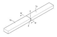
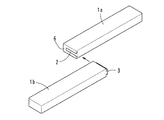
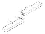
この発明に係る文鎮の第一実施形態を図1から図9に示す。この文鎮は、一本の角棒状の文鎮を、その長さ方向のほぼ中央で二つに分割した分割式のものである(図1及び図2を参照)。分割した一方の分割片1aの端部には、あり溝状の凹溝2が形成されるとともに、この分割片1aと連結する他方の分割片1bの端部には、この凹溝2に嵌って抜き挿しされる突条3が形成されている(図3を参照)。この凹溝2と突条3を嵌合させて、その長さ方向の連結がなされる。
A first embodiment of a paperweight according to the present invention is shown in FIGS. This paperweight is of a split type in which a square paper-shaped paperweight is divided into two at almost the center in the length direction (see FIGS. 1 and 2). A
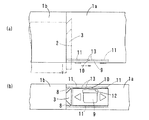
各分割片1a、1bは、角棒状の鉄製基材4上に、約3mm厚のABS樹脂層5を形成することによって形成されている(図4を参照)。凹溝2及び突条3の部分はABS樹脂層5のみで構成されている。このため、鉄製基材4自体を凹溝2及び突条3の形状に加工する必要はなく、ABS樹脂材の射出成型などの成形法によって、この凹溝2及び突条3を簡便に形成することができる。両分割片1a、1bの嵌合強度をより高めるために、鉄製基材4自体を凹溝2及び突条3に加工することもできる。
Each divided
この凹溝2の一端側(挿し込み方向の奥側)には壁部6が形成されていて、一方の分割片1aを他方の分割片1bに所定深さまで挿し込んだ際に、この他方の分割片1bに形成した突条3の先端が壁部6に当接するようになっている。この当接により、嵌合した分割片1a、1bが、少なくともその当接方向に抜け落ちるトラブルを防止することができるとともに、両分割片1a、1bの連結する際の位置合わせを一層速やかに行うことができるため利便性が高い。なお、この壁部6を設けない構成としても、連結強度自体には影響しない。
A
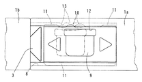
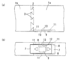
この文鎮の連結状態を一層確実なものとするため、図5から図8に示すように、ロック機構を設けることもできる。このロック機構においては、一方の分割片1aの側面に凹部7を形成するとともに、この凹部7内に、対向する一対の案内溝8、8を形成する。そして、この案内溝8にABS樹脂材からなるスライド片9をスライド自在に設ける(図5を参照)。
In order to further secure the connection state of the paperweights, a lock mechanism can be provided as shown in FIGS. In this locking mechanism, a
このスライド片9の一方の端辺には、案内溝8側に突出する第一突起10と、この第一突起10に対してスライド方向の両側に、第一突起10より高さが低い案内突起11が形成されている。スライド片9の本体には、第一突起10に近接して貫通孔12が形成されている。このスライド片9の前記一方の端辺と反対側の他方の端辺には、スライド方向の全長に亘って案内突起11が形成されている。第一突起10のみで、スライド片9のスライド機能を確保できる場合は、この第一突起10の両側の案内突起11を設けない構成としたり、片方のみ設ける構成としたりすることもできる。
On one end of the
一方の分割片1aの第一突起10と対向する案内溝8には、一対の第二突起13、13が形成されている。この第二突起13は、スライド片9がスライドした際に、第一突起10と当接する一方で、案内突起11、11とは接触しない程度の高さとなっている。
A pair of
両分割片1a、1bを連結し、スライド片9を他方の分割片1b側にスライドした状態で分割片同士を抜き差ししようとしても、このスライド片9が他方の分割片1bの突条3の端部に当接して、その抜き挿しが自在にできない状態(ロック状態)となる(図6を参照)。このとき、スライド片9の第一突起10が、一対の第二突起13の間にちょうど嵌まり込んだ状態となっている。このため、スライド片9が不用意にスライドして、このロック状態が解除される恐れは低い。
Even if both the
このロック状態から、スライド片9を一方の分割片1a側にスライドすると、ロック状態が解除されて(図7を参照)、分割片同士を自在に抜き差しすることができる。
When the
このロック及びロック解除の過程においては、第一突起10が第二突起13を一旦乗り越える必要がある。この乗り越えに際し、図8に示すように、第一突起10と第二突起13の当接力によって、この第一突起10が、スライド片9に形成した貫通孔12側に一旦退去する。このため、この乗り越えが容易となって、ロック及びロック解除をスムーズに行うことができる。
In the process of locking and unlocking, it is necessary for the
この文鎮は、連結状態として通常の文鎮と同様に使用できる一方で、図9に示すように、書道用の半紙P等の上下端側に各分割片1a、1bを置くことにより、この半紙Pの下端側を手で押さえることなくスムーズに筆を走らせることができる。
This paperweight can be used in the same manner as a normal paperweight as a connected state. On the other hand, as shown in FIG. 9, by placing the divided
この第一実施形態においては、分割片1a、1bに水平方向に延びる凹溝2及び突条3を形成する構成としたが、垂直方向に延びる凹溝2及び突条3を形成し、両分割片1a、1bの抜き挿し方向に垂直な面にスライド片9を設ける構成とすることもできる。
In this first embodiment, the divided
この発明に係る文鎮の第二の実施形態を図10から図13に示す。この文鎮は、第一実施形態と同様に、一本の角棒状の文鎮を、その長さ方向のほぼ中央で二つに分割した分割式のものである(図10及び図11を参照)。分割した一方の分割片1aの端部には、あり溝状の凹部2が形成されるとともに、この一方の分割片1aと連結する他方の分割片1bの端部には、この凹溝2に嵌ってスライドする突条3が形成されている。
A second embodiment of the paperweight according to the present invention is shown in FIGS. As in the first embodiment, this paperweight is of a split type in which a square paper-shaped paperweight is divided into two at almost the center in the length direction (see FIGS. 10 and 11). A
この第二実施形態においては、凹溝2及び突条3が複数本並列して形成されている。このように複数本並列して、両者の間の嵌合力を高めることによって、連結した分割片が不用意にスライドして分離してしまうトラブルを極力防止することができる。
In this second embodiment, a plurality of
この第二実施形態においては、図12及び図13に示すように、ロック機構を設けることもできる。このロック機構においては、連結する両分割片1a、1bの側面に跨る凹部7を形成するとともに、この凹部7内に、対向する一対の案内溝8、8を形成する。そして、この案内溝8にABS樹脂材からなるスライド片9をスライド自在に設ける。第一実施形態と同様に、このスライド片9には第一突起10及び案内突起11が形成されるとともに、案内溝8には第二突起13が形成されている。各突起10、11、13の作用は第一実施形態において説明したので、その説明は省略する。
In the second embodiment, a lock mechanism can be provided as shown in FIGS. In this locking mechanism, a
両分割片1a、1bを連結し、スライド片9を他方の分割片1b側にスライドした状態で分割片同士を抜き差ししようとすると、このスライド片9が他方の分割片1bの凹部7の側壁に当接して、ロック状態となる(図12を参照)。このロック状態から、スライド片9を一方の分割片1a側にスライドすると、ロック状態が解除されて(図13を参照)、分割片同士を自在に抜き差しすることができる。
If both the
この第二実施形態においては、抜き差し方向に垂直な側面にスライド片9を設ける構成としたが、抜き差し方向に平行な側面にスライド片9を設ける構成とすることもできる。この場合、スライド片9と他方の分割片1bに形成した凹部7の底面とが当接することによってロック作用が発揮される。
In the second embodiment, the
上記の各実施形態においては、二つの分割片1a、1bを連結して一本の角棒状の文鎮を構成する態様について示したが、文鎮の分割数はもちろんこれに限定されず、さらに多分割の構成とすることもできる。
In each of the above-described embodiments, a mode has been described in which two divided
また、各分割片1a、1b、スライド片9の素材は、ロック機構の機能が発揮される限りにおいて、適宜変更することができる。また、第一及び第二実施形態における凹溝2及び突条3、スライド片9の形状は例示であって、両分割片1a、1bの連結作用、ロック機構の機能が発揮される限りにおいて、適宜他の形状を採用することもできる。
Moreover, the raw material of each division |
1a (一方の)分割片
1b (他方の)分割片
2 凹溝
3 突条
4 鉄製基材
5 ABS樹脂層
6 壁部
7 凹部
8 案内溝
9 スライド片
10 第一突起
11 案内突起
12 貫通孔
13 第二突起
1a (one) divided
Claims (6)
Priority Applications (1)
| Application Number | Priority Date | Filing Date | Title |
|---|---|---|---|
| JP2012031414A JP2013166319A (en) | 2012-02-16 | 2012-02-16 | Paperweight |
Applications Claiming Priority (1)
| Application Number | Priority Date | Filing Date | Title |
|---|---|---|---|
| JP2012031414A JP2013166319A (en) | 2012-02-16 | 2012-02-16 | Paperweight |
Publications (1)
| Publication Number | Publication Date |
|---|---|
| JP2013166319A true JP2013166319A (en) | 2013-08-29 |
Family
ID=49177151
Family Applications (1)
| Application Number | Title | Priority Date | Filing Date |
|---|---|---|---|
| JP2012031414A Pending JP2013166319A (en) | 2012-02-16 | 2012-02-16 | Paperweight |
Country Status (1)
| Country | Link |
|---|---|
| JP (1) | JP2013166319A (en) |
Cited By (1)
| Publication number | Priority date | Publication date | Assignee | Title |
|---|---|---|---|---|
| CN106364238A (en) * | 2016-09-30 | 2017-02-01 | 太仓福缘琉璃工艺品有限公司 | Paperweight glass artware convenient for adjustment and use |
Citations (1)
| Publication number | Priority date | Publication date | Assignee | Title |
|---|---|---|---|---|
| JPS6325599U (en) * | 1986-07-31 | 1988-02-19 |
-
2012
- 2012-02-16 JP JP2012031414A patent/JP2013166319A/en active Pending
Patent Citations (1)
| Publication number | Priority date | Publication date | Assignee | Title |
|---|---|---|---|---|
| JPS6325599U (en) * | 1986-07-31 | 1988-02-19 |
Cited By (1)
| Publication number | Priority date | Publication date | Assignee | Title |
|---|---|---|---|---|
| CN106364238A (en) * | 2016-09-30 | 2017-02-01 | 太仓福缘琉璃工艺品有限公司 | Paperweight glass artware convenient for adjustment and use |
Similar Documents
| Publication | Publication Date | Title |
|---|---|---|
| US9178309B2 (en) | Socket with a metal fitting with a lock portion movable in a width direction | |
| US9820404B1 (en) | Slot assembly and workpiece | |
| US9167717B2 (en) | Connection device for cable management arm and slide assembly | |
| US20070253794A1 (en) | Fastening device | |
| US20090137142A1 (en) | Positive lock connector | |
| TWI511680B (en) | Buckle | |
| CN105264716A (en) | Connector | |
| TWM482871U (en) | Electronic connector module | |
| US20150325950A1 (en) | Lever type connector | |
| CN100572831C (en) | Ball slide | |
| US10133009B1 (en) | Fiber optic adaptor | |
| JP2013166319A (en) | Paperweight | |
| JP6306387B2 (en) | Connector removal prevention device | |
| CN204205169U (en) | A kind of quick locking rectangular connector | |
| CN107039840A (en) | Connector | |
| JP6587595B2 (en) | Lever type connector | |
| US20060154506A1 (en) | Card connector | |
| US20200039058A1 (en) | Reversible wrench rack | |
| KR101347433B1 (en) | Lock releasing mechanism | |
| CN103022838B (en) | Connector with a locking member | |
| JP6830809B2 (en) | Long object feeding device | |
| JP2010099291A (en) | Linkage mechanism | |
| EP2156520A1 (en) | Holder for two plugs | |
| JP5959863B2 (en) | Locking device | |
| WO2014177981A1 (en) | Connector plug and connector assembly |
Legal Events
| Date | Code | Title | Description |
|---|---|---|---|
| A621 | Written request for application examination |
Free format text: JAPANESE INTERMEDIATE CODE: A621 Effective date: 20150213 |
|
| RD13 | Notification of appointment of power of sub attorney |
Free format text: JAPANESE INTERMEDIATE CODE: A7433 Effective date: 20150213 |
|
| A521 | Written amendment |
Free format text: JAPANESE INTERMEDIATE CODE: A821 Effective date: 20150213 |
|
| A131 | Notification of reasons for refusal |
Free format text: JAPANESE INTERMEDIATE CODE: A131 Effective date: 20160119 |
|
| A02 | Decision of refusal |
Free format text: JAPANESE INTERMEDIATE CODE: A02 Effective date: 20160524 |