JP2013166317A - Knurling roller, apparatus, method of manufacturing film roll, and optical film - Google Patents
Knurling roller, apparatus, method of manufacturing film roll, and optical film Download PDFInfo
- Publication number
- JP2013166317A JP2013166317A JP2012031352A JP2012031352A JP2013166317A JP 2013166317 A JP2013166317 A JP 2013166317A JP 2012031352 A JP2012031352 A JP 2012031352A JP 2012031352 A JP2012031352 A JP 2012031352A JP 2013166317 A JP2013166317 A JP 2013166317A
- Authority
- JP
- Japan
- Prior art keywords
- knurling
- protrusion
- polymer film
- recess
- film
- Prior art date
- Legal status (The legal status is an assumption and is not a legal conclusion. Google has not performed a legal analysis and makes no representation as to the accuracy of the status listed.)
- Granted
Links
Images


Classifications
-
- B—PERFORMING OPERATIONS; TRANSPORTING
- B29—WORKING OF PLASTICS; WORKING OF SUBSTANCES IN A PLASTIC STATE IN GENERAL
- B29C—SHAPING OR JOINING OF PLASTICS; SHAPING OF MATERIAL IN A PLASTIC STATE, NOT OTHERWISE PROVIDED FOR; AFTER-TREATMENT OF THE SHAPED PRODUCTS, e.g. REPAIRING
- B29C59/00—Surface shaping of articles, e.g. embossing; Apparatus therefor
- B29C59/02—Surface shaping of articles, e.g. embossing; Apparatus therefor by mechanical means, e.g. pressing
- B29C59/04—Surface shaping of articles, e.g. embossing; Apparatus therefor by mechanical means, e.g. pressing using rollers or endless belts
-
- B—PERFORMING OPERATIONS; TRANSPORTING
- B65—CONVEYING; PACKING; STORING; HANDLING THIN OR FILAMENTARY MATERIAL
- B65H—HANDLING THIN OR FILAMENTARY MATERIAL, e.g. SHEETS, WEBS, CABLES
- B65H27/00—Special constructions, e.g. surface features, of feed or guide rollers for webs
-
- F—MECHANICAL ENGINEERING; LIGHTING; HEATING; WEAPONS; BLASTING
- F16—ENGINEERING ELEMENTS AND UNITS; GENERAL MEASURES FOR PRODUCING AND MAINTAINING EFFECTIVE FUNCTIONING OF MACHINES OR INSTALLATIONS; THERMAL INSULATION IN GENERAL
- F16C—SHAFTS; FLEXIBLE SHAFTS; ELEMENTS OR CRANKSHAFT MECHANISMS; ROTARY BODIES OTHER THAN GEARING ELEMENTS; BEARINGS
- F16C13/00—Rolls, drums, discs, or the like; Bearings or mountings therefor
-
- B—PERFORMING OPERATIONS; TRANSPORTING
- B65—CONVEYING; PACKING; STORING; HANDLING THIN OR FILAMENTARY MATERIAL
- B65H—HANDLING THIN OR FILAMENTARY MATERIAL, e.g. SHEETS, WEBS, CABLES
- B65H2404/00—Parts for transporting or guiding the handled material
- B65H2404/10—Rollers
- B65H2404/19—Other features of rollers
-
- B—PERFORMING OPERATIONS; TRANSPORTING
- B65—CONVEYING; PACKING; STORING; HANDLING THIN OR FILAMENTARY MATERIAL
- B65H—HANDLING THIN OR FILAMENTARY MATERIAL, e.g. SHEETS, WEBS, CABLES
- B65H2701/00—Handled material; Storage means
- B65H2701/10—Handled articles or webs
- B65H2701/17—Nature of material
- B65H2701/175—Plastic
- B65H2701/1752—Polymer film
-
- F—MECHANICAL ENGINEERING; LIGHTING; HEATING; WEAPONS; BLASTING
- F16—ENGINEERING ELEMENTS AND UNITS; GENERAL MEASURES FOR PRODUCING AND MAINTAINING EFFECTIVE FUNCTIONING OF MACHINES OR INSTALLATIONS; THERMAL INSULATION IN GENERAL
- F16C—SHAFTS; FLEXIBLE SHAFTS; ELEMENTS OR CRANKSHAFT MECHANISMS; ROTARY BODIES OTHER THAN GEARING ELEMENTS; BEARINGS
- F16C2322/00—Apparatus used in shaping articles
- F16C2322/12—Rolling apparatus, e.g. rolling stands, rolls
Landscapes
- Engineering & Computer Science (AREA)
- Mechanical Engineering (AREA)
- General Engineering & Computer Science (AREA)
- Shaping Of Tube Ends By Bending Or Straightening (AREA)
- Advancing Webs (AREA)
- Rolls And Other Rotary Bodies (AREA)
- Moulding By Coating Moulds (AREA)
Abstract
【課題】経時変化による凹凸の緩和を抑えたナーリングを形成する。
【解決手段】ローラ本体21aの外周面に多数の突起からなるナーリング歯40を略マトリックス状に配置し、ナーリングローラ21を構成する。各ナーリング歯40を、先端平坦面を有する突起と、先端平坦面に形成される補強部形成凹部とから構成する。ナーリング歯の突起により、凹部32aとこの凹部32aを囲む囲繞隆起部32bがポリマーフィルム15に転写される。補強部形成凹部により、ナーリング突起32の凹部32a内に、補強突部32dが形成される。補強突部32dにより、凹部32a及び囲繞隆起部32bの高さが維持されるため、経時変化に対する凹凸量の緩和がなくなる。経時変化によるナーリング突起32のヘタリが抑えられるため、フィルムロールの輸送時にフィルム同士が擦れたり、巻きずれが発生することが無くなる。
【選択図】図4[PROBLEMS] To form a knurling that suppresses relief of unevenness due to a change over time.
A knurling roller 21 is configured by arranging knurling teeth 40 formed of a large number of protrusions on a peripheral surface of a roller body 21a in a substantially matrix shape. Each knurling tooth 40 includes a protrusion having a flat tip surface and a reinforcing portion forming recess formed on the flat tip surface. By the projection of the knurling teeth, the concave portion 32a and the surrounding raised portion 32b surrounding the concave portion 32a are transferred to the polymer film 15. A reinforcing protrusion 32d is formed in the recess 32a of the knurling protrusion 32 by the reinforcing portion forming recess. Since the height of the concave portion 32a and the surrounding raised portion 32b is maintained by the reinforcing protrusion 32d, the amount of unevenness with respect to changes over time is eliminated. Since the settling of the knurling protrusion 32 due to a change with time is suppressed, the films are not rubbed or unwound when the film roll is transported.
[Selection] Figure 4
Description
本発明は、ナーリングローラ、装置、フィルムロール製造方法及び光学フィルムに関する。 The present invention relates to a knurling roller, an apparatus, a film roll manufacturing method, and an optical film.
ポリマーフィルムは、優れた光透過性や柔軟性を有し、軽量薄膜化が可能であるなどの特長から光学フィルム等として多岐に利用されている。中でも、セルロースアシレートなどを用いたセルロースエステル系フィルムは、写真感光用フィルムをはじめとして、近年市場が拡大している液晶表示装置の構成部材である偏光板の保護フィルムや位相差フィルム等の光学フィルムに用いられている。 Polymer films are widely used as optical films and the like because of their features such as excellent light transmission and flexibility, and being capable of reducing the weight of thin films. Among them, cellulose ester films using cellulose acylate and the like are optical films such as a protective film for a polarizing plate and a retardation film, which are constituent members of liquid crystal display devices whose market is expanding in recent years, including photographic photosensitive films. Used in film.
ポリマーフィルムは、溶融製膜方法や溶液製膜方法等によって帯状に連続して製造され、巻き芯にロール状に巻き取られて、フィルムロールとして保管され、輸送される。フィルムロールにおけるポリマーフィルムの巻きズレや巻き緩みを防ぐために、ポリマーフィルムの幅方向両側縁部(以下、耳部と称する)に微小な凹凸からなるナーリングが形成される(例えば、特許文献1)。 The polymer film is continuously produced in a band shape by a melt film forming method, a solution film forming method, or the like, wound around the winding core in a roll shape, stored as a film roll, and transported. In order to prevent winding deviation or loosening of the polymer film in the film roll, knurling composed of minute irregularities is formed on both side edges (hereinafter referred to as ears) in the width direction of the polymer film (for example, Patent Document 1).
ナーリングが形成された耳部は、他の製品となる製品部よりもナーリングが付与された分だけ厚くなる。したがって、ナーリングを有するポリマーフィルムをロール状に巻き取ると、フィルムロールにおいて、製品部が陥没してしまう陥没故障が発生することがある。特許文献1では、このような陥没故障を防止するために、製品部における厚み分布が、両側縁から中央部に向かうに従い次第に薄くなるポリマーフィルムが開示されている。
The ear part in which the knurling is formed is thicker than the product part to be the other product by the amount of the knurling. Accordingly, when a polymer film having a knurling is wound up in a roll shape, a collapse failure in which a product portion is depressed may occur in the film roll.
ところが、特許文献1のようにして、耳部にナーリングが形成されたポリマーフィルムを巻き芯に巻き取った場合であっても、耳部及び製品部の間の微小な膜厚差の積み重なりが、フィルムロールの外周面に段差となって現れてしまう。このような段差が生じたフィルムロールにポリマーフィルムを押しつけながら、巻き取っていくと、段差部分に応力が集中する。これにより、ポリマーフィルムのうち、耳部及びその付近が伸びてしまういわゆる耳伸びが発生する。この耳伸びにより、製品部、特に耳部付近の製品部の厚みが変動する結果、光学特性や機械特性が製品部全体として均一にならない不都合がある。
However, as in
このような耳伸びを解消するために、巻き取り張力や押圧ロールによる圧力を小さくすることも可能であるが、この場合には、巻きずれや巻き緩みが発生してしまう。また、ナーリングの高さを低くすることにより、耳伸びは発生し憎くなるものの、巻きずれや巻き緩みが発生しやすくなる。更に、近年では、ディスプレイ等の最終製品の大型化や製造効率化に伴い、フィルムロールの全長が長くなる長尺化、幅が広くなる幅広化の要請がある。したがって、フィルムロールの長尺化、幅広化によって、上記陥没故障が起こり易くなるという問題がある。 In order to eliminate such an extension of the ear, it is possible to reduce the take-up tension or the pressure by the pressing roll, but in this case, winding deviation or winding looseness occurs. Further, by lowering the height of the knurling, although the ear stretch is generated and hated, winding slippage and loosening are likely to occur. Furthermore, in recent years, with the enlargement and production efficiency of final products such as displays, there has been a demand for an increase in the length of the film roll and an increase in the width of the film roll. Therefore, there is a problem that the above-mentioned depression failure is likely to occur due to the lengthening and widening of the film roll.
これに対して、特許文献2では、ナーリングの突端に設けられた稜線の長さの総和を一定範囲内にすることにより、巻きずれや巻き緩みの防止と、耳伸びの防止との両立を可能にしている。また、ポリマーフィルムの長尺化や幅広化に対応して陥落故障も抑制される。
On the other hand, in
しかしながら、特許文献2のように、突起を改良して、巻きずれや巻き緩みの防止を図っても、ロール状に巻き取られたポリマーフィルムの面圧によって、時間の経過とともに、突起が変形し、凹凸が緩和され、突起によるフィルムの保持力が低下することがある。特に、長尺化や幅広化に対応したフィルムロールの場合にこの経時変化が顕著であり、新たな対策が望まれている。
However, as in
本発明は、このような課題を解決するものであり、ナーリングの経時変化による凹凸の緩和を抑制することができるナーリングローラ、装置、ウェブロール製造方法及び光学フィルムを提供することを目的とする。 This invention solves such a subject, and it aims at providing the knurling roller, the apparatus, the web roll manufacturing method, and optical film which can suppress the relief | moderation of the unevenness | corrugation by the time-dependent change of knurling.
上記目的を達成するために、本発明は、ウェブにナーリングを付与するためのナーリング歯を、ローラ本体の外周面に有するナーリングローラにおいて、前記ナーリング歯を、先端が平坦に突出する突起と、前記突起の先端平坦面に形成される補強部形成凹部とから構成することを特徴とする。 In order to achieve the above object, the present invention provides a knurling roller having knurling teeth for imparting knurling to a web on an outer peripheral surface of a roller body, the knurling teeth including a protrusion whose tip protrudes flatly, It is comprised from the reinforcement part formation recessed part formed in the front-end | tip flat surface of a processus | protrusion.
なお、前記突起によりウェブに形成される凹部と、前記凹部の周囲を囲むように突出する囲繞隆起部と、前記補強部形成凹部により前記凹部内に形成される補強突部とからナーリング突起を構成することが好ましい。また、前記補強部形成凹部は、丸穴、角穴、円錐台穴、角錐台穴、I字溝、Y字溝、クロス溝のいずれかから構成されることが好ましい。 A knurling protrusion is constituted by a recess formed in the web by the protrusion, a surrounding bulging portion protruding so as to surround the periphery of the recess, and a reinforcing protrusion formed in the recess by the reinforcing portion forming recess. It is preferable to do. Moreover, it is preferable that the said reinforcement part formation recessed part is comprised from either a round hole, a square hole, a truncated cone hole, a truncated pyramid hole, an I-shaped groove, a Y-shaped groove, or a cross groove.
本発明のナーリング装置は、上記ナーリングローラにより、前記ウェブの両側縁部にナーリングを形成することを特徴とする。また、連続的に製造される帯状のポリマーフィルムからフィルムロールを製造するフィルムロール製造方法では、上記ナーリング装置を用い、前記ポリマーフィルムの両側縁部にナーリングを形成するナーリング形成工程と、前記ポリマーフィルムをロール状に巻き取るウェブ巻き取り工程とを含むことを特徴とする。 The knurling device of the present invention is characterized in that knurling is formed on both side edges of the web by the knurling roller. Moreover, in the film roll manufacturing method which manufactures a film roll from the strip | belt-shaped polymer film manufactured continuously, the knurling formation process which forms a knurling in the both-sides edge part of the said polymer film using the said knurling apparatus, and the said polymer film And a web winding process for winding the film into a roll.
本発明の光学フィルムは、帯状のポリマーフィルムの幅方向にエンボス加工によりナーリング突起を並べて突起列を構成し、前記突起列を前記ポリマーフィルムの長手方向に一定ピッチで並べてナーリングを構成し、前記ナーリングを前記ポリマーフィルムの両側縁部に有する光学フィルムであって、前記ナーリング突起は、前記ポリマーフィルムの一方の面に形成される凹部と、前記凹部を囲むように突出する囲繞隆起部と、前記凹部内に突出する補強突部と、前記ポリマーフィルムの他方の面に前記凹部に対応して突出する裏面突起とを有することを特徴とする。なお、前記補強突部は、円柱、角柱、円錐台、角錐台、I字状突条、Y字状突条、クロス状突条のいずれか一つから構成されることが好ましい。また、前記補強突部の凹部内での突出高さをH1、前記凹部の底面から前記囲繞隆起部の頂部までの高さをH2としたときに、0.3≦(H1/H2)≦1.0であることが好ましい。前記囲繞隆起部の頂部により囲まれる面積をS1、前記補強突部の頂部の面積をS2としたときに、0.05≦(S2/S1)≦0.5であることが好ましい。 The optical film of the present invention is configured such that a knurling is formed by arranging knurling protrusions in a width direction of a band-shaped polymer film by embossing, and a knurling is formed by arranging the protrusions in a longitudinal direction of the polymer film. At the both side edges of the polymer film, wherein the knurling protrusion includes a recess formed on one surface of the polymer film, a surrounding ridge protruding so as to surround the recess, and the recess. It has a reinforcing protrusion protruding inward and a back protrusion protruding corresponding to the recess on the other surface of the polymer film. In addition, it is preferable that the said reinforcement protrusion is comprised from any one of a cylinder, a prism, a truncated cone, a truncated pyramid, an I-shaped protrusion, a Y-shaped protrusion, and a cross-shaped protrusion. Further, when the height of protrusion of the reinforcing protrusion in the concave portion is H1, and the height from the bottom surface of the concave portion to the top of the surrounding raised portion is H2, 0.3 ≦ (H1 / H2) ≦ 1 0.0 is preferred. It is preferable that 0.05 ≦ (S2 / S1) ≦ 0.5, where S1 is an area surrounded by the top of the surrounding raised portion and S2 is an area of the top of the reinforcing protrusion.
本発明によれば、先端が平坦に突出する突起と、前記突起の先端平坦面に形成される補強部形成凹部とからナーリング歯を構成したので、このナーリング歯を用いてポリマーフィルムをエンボス加工することにより、ナーリング突起が形成される。このナーリング突起は、ポリマーフィルムの一方の面に形成される凹部と、この凹部を囲むように突出する囲繞隆起部と、前記凹部内に突出する補強突部と、前記ポリマーフィルムの他方の面に前記凹部に対応して突出する裏面突起とを有する。凹部の中に、補強突部が突出して形成されるため、補強突部が凹部及び囲繞隆起部の補強材として作用する。これにより、経時変化によって凹部や囲繞隆起部の凹凸が緩和されることが無くなり、いわゆるナーリング突起のヘタリが抑制される。 According to the present invention, the knurling teeth are constituted by the protrusions whose tips protrude flatly and the reinforcing portion forming recesses formed on the tip flat surface of the protrusions, and the polymer film is embossed using the knurling teeth. As a result, a knurling protrusion is formed. The knurling protrusion includes a recess formed on one surface of the polymer film, a surrounding ridge protruding so as to surround the recess, a reinforcing protrusion protruding into the recess, and the other surface of the polymer film. And a rear surface protrusion protruding corresponding to the recess. Since the reinforcing protrusion protrudes in the recess, the reinforcing protrusion acts as a reinforcing material for the recess and the surrounding raised portion. As a result, the unevenness of the concave portion and the surrounding raised portion is not alleviated due to the change with time, and so-called knurling protrusions are prevented from becoming loose.
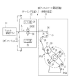
図1に示すように、本発明のフィルムロール製造設備10は、フィルム製造ライン11、ナーリング装置12、巻取り装置13を有する。フィルム製造ライン11は、図示は省略したが、流延装置、テンタ、乾燥装置を順に有し、例えば溶液製膜方法により、帯状のポリマーフィルム15、例えばTAC(トリアセチルセルロース)フィルムを製造する。
As shown in FIG. 1, the film
巻取り装置13は、ターレットアーム16を有し、巻取り軸17にセットされた巻き芯18にポリマーフィルム15を巻き取る。ターレットアーム16は図示しないアーム駆動部によって180度間欠回転し、巻き芯18を巻取り位置PS1と、巻き芯交換位置PS2とに選択的に切り換える。なお、ターレットアーム16の回転方向の中間位置には、ガイドアーム27が設けられており、ガイドアーム27の先端部にはガイドローラ28が取り付けられている。ガイドローラ28は、ターレットアーム16が回転しているときに、ポリマーフィルム15がターレットアーム16やアーム取付軸29に接触することがないように、ポリマーフィルム15を支持する。
The
ターレットアーム16の先端部には巻取り軸17が設けられており、この巻取り軸17に巻き芯18がセットされる。巻取り位置PS1では、ガイドローラ26から送られてくるポリマーフィルム15を巻き芯18に巻き取る。また、巻き芯交換位置PS2では、一定長さのポリマーフィルム15を巻き取って満巻きとなったフィルムロール19を巻き芯18と一緒に巻取り軸17から取り外し、この巻取り軸17には新たな空の巻き芯18がセットされ、巻き芯18の交換が行われる。
A winding
巻取り位置PS1で、所定の長さのポリマーフィルム15が巻き芯18に巻き取られて、フィルムロール19が満巻きに近い状態になると、ターレットアーム16が180度回転し、巻き芯交換位置PS2に満巻きに近いフィルムロール19を位置させる。また、巻取り位置PS1には空の巻き芯18が位置決めされる。フィルムロール19が所定の長さとなると、図示しない巻替え装置が作動して、ポリマーフィルム15が切断される。切断された先行フィルムの後端部は巻き芯交換位置PS2にてフィルムロール19に巻き取られる。また、切断された後行フィルムの先端部は巻取り位置PS1にて空の巻き芯18に巻き取られる。
When the
以下、同じように、巻き芯18にポリマーフィルム15が巻き取られることにより、連続して送られてくるポリマーフィルム15がフィルムロール19の形態として、製品となる。このようにして得られたポリマーフィルム15は、偏光板保護フィルムや位相差フィルムとして用いられる。また、ポリマーフィルム15に光学的異方性層、反射防止層、防眩機能層等が付与され、高機能フィルムとして用いられる。
Hereinafter, in the same manner, the
ナーリング装置12は、フィルム製造ライン11と巻取り装置13との間に配置される。ナーリング装置12は、支持ローラ20と、ナーリングローラ21,22と、シフト部23,24とを備えている。そして、ナーリング付与時には、シフト部23によって支持ローラ20が上昇し、シフト部24によってナーリングローラ21,22が下降して、これらローラ20,21,22がポリマーフィルム15をニップする位置に移動する。フィルムニップ位置に各ローラ20〜22が移動すると、図2に示すように、フィルム両側縁部(耳部)15a,15bがこれらローラ20〜22によって挟持され、エンボス加工によって両耳部15a,15bにナーリング30,31が形成される。また、退避位置にセットされると、各ローラ20〜22がポリマーフィルム15から離れるように退避する。
The
図3に示すように、各ローラ20,21,22にはヒータ25が設けられている。ヒータ25は、ポリマーフィルム15を任意の温度に調節する。これにより、適温にてナーリング30,31が両耳部15a,15bに付与される。
As shown in FIG. 3, each
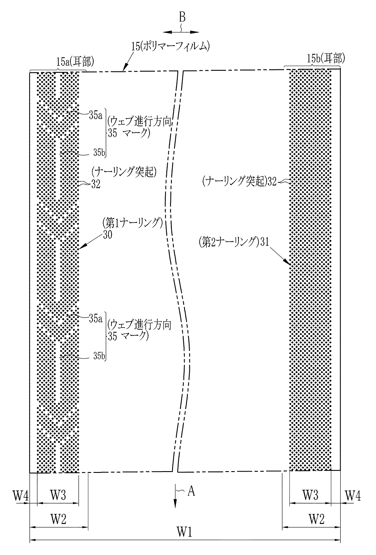
ナーリング30,31は、微小なナーリング突起32が略マトリックス状に配置されて構成される。本実施形態では、矢印Aで示すポリマーフィルム15の進行方向に向かって例えば右側(以下、単に右側と称する)耳部15aに、第1ナーリングローラ21が配置される。第1ナーリングローラ21は、図5に示すように、外周面にウェブ進行方向マーク33を有する。この第1ナーリングローラ21によって、ポリマーフィルム15の右側耳部15aには、ウェブ進行方向マーク35を有する第1ナーリング30が形成される。なお、ポリマーフィルム15の幅方向を矢印Bで示す。
The
ポリマーフィルム15の進行方向に向かって左側(以下、単に左側と称する)耳部15bには、第2ナーリングローラ22が配置される。この第2ナーリングローラ22によって、ポリマーフィルム15の左側耳部15bには微小なナーリング突起32が略マトリックスに配置された通常パターンの第2ナーリング31が形成される。
A
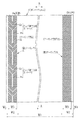
図4に示すように、第1ナーリングローラ21は、ローラ本体21aと、このローラ本体21aの外周面に設けた複数個の突起からなるナーリング歯40を有する。支持ローラ20は外周面が平滑なローラ本体20aからなり、ナーリングローラ21のナーリング歯40のような突起などは形成されることがない。
As shown in FIG. 4, the
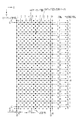
第1ナーリングローラ21の外周面の展開図を示す図5において、ローラ本体21aの外周面で、軸方向(X方向)に平行に、ナーリング歯列41が形成される。ナーリング歯列41は、ナーリング歯40を一定ピッチP1で10個並べて形成することができる長さ(L1)となっており、その内の1個にはナーリング歯40が形成されることなく、隙間42となっている。この隙間42がマーク形成用隙間となる。なお、図5においては隙間42を明確化するために、「●」によって、隙間42を図示している。
In FIG. 5 showing a development view of the outer peripheral surface of the
隣接するナーリング歯列41は、ナーリング歯40の1/2ピッチ分(P1/2)だけ、ローラ本体21aの軸方向(矢印X)にずらしてあり、これによって、隣接するナーリング歯列41は、各ナーリング歯40が千鳥状になるように配置される。本実施形態では、ローラ本体21aの軸方向を列方向(X方向)とし、ローラ本体21aの周方向を行方向(矢印Yで表し、Y方向とも称する)としている。図5において、Y方向には一定ピッチで48行のナーリング歯列41が形成される。また、ローラ本体21aの軸方向には、隣接するナーリング歯列41の各ナーリング歯40が半ピッチ分だけ、ずれて配置されるため、20列のナーリング歯行43が形成される。
The
本発明では、千鳥状にずれた1組のナーリング歯列41に対して、1〜10の同一列位置番号が順に付してある。そして、行番号と列番号で特定された略マトリックス配置において、マーク形成用隙間42の位置を行番号及び列位置番号で特定している。図5では、左側に、各ナーリング歯列41の隙間位置が「●」で図示してあり、右側に各行における空き列位置番号(隙間が位置する列位置番号)が表示してある。このような行番号及び列位置番号とで隙間位置が特定された空き列位置パターンとすることにより、図6に示すように、フィルムの進行方向(A方向)にVマーク35aとYマーク35bとが交互に連続するウェブ進行方向マーク35が形成される。
In the present invention, the same row position numbers of 1 to 10 are assigned in order to a set of
図7の展開図に示すように、第2ナーリングローラ22は、ナーリング歯40を9個用いて、第2ナーリング31の幅W2となるように一定ピッチで配置したナーリング歯列41を、周方向に48行形成して、略マトリックス状にナーリング歯40を配置したものである。なお、第1ナーリングローラ21と同様に、隣接するナーリング歯列41は半ピッチ分だけずらしてあり、各ナーリング歯40が千鳥状の配置となるようにしてある。
As shown in the development view of FIG. 7, the
図6に示すように、ポリマーフィルム15の一方の耳部15aに、ウェブ進行方向を表すウェブ進行方向マーク35を有する第1ナーリング30が形成され、他方の耳部15bにノーマルパターンの第2ナーリング31が形成されることにより、この一方の耳部15aに形成されたウェブ進行方向マーク35により、製膜時の両サイドや表裏を識別することができる。
As shown in FIG. 6, a
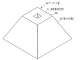
図8に示すように、ナーリング歯40は、本実施形態では、角錐の頂部を底面に平行に切り落とした平坦面50aを有する截頭角錐状(角錐台状)の突起50と、この突起50の先端平坦面50aに形成される截頭角錐状穴からなる補強部形成凹部51とを有する。
As shown in FIG. 8, the
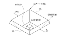
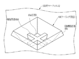
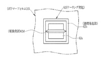
図9に示すように、ナーリング歯40(図8参照)によってポリマーフィルム15に転写される微小なナーリング突起32は、ナーリング歯40の突起50がフィルム面に食い込むことにより転写される凹部32aと、この凹部32aの凹みと共に周囲が隆起して形成され、断面が山形状(図10参照)で凹部32aを囲むように形成される矩形状の囲繞隆起部32bと、図4に示すように、凹部32aに対応してポリマーフィルム15の反対面側に突出し、略截頭角錐状の裏面凸部32cと、前記補強部形成凹部51により転写される截頭角錐状の補強突部32dとから構成される。
As shown in FIG. 9, the
図10に示すように、囲繞隆起部32bのポリマーフィルム面からの高さH3は、ポリマーフィルム15の厚みによって変化するが、厚みが40μm以上100μm以下の場合には、3μm以上30μm以下であることが好ましく、3μm以上15μm以下であることがより好ましく、3μm以上9μm以下であることが特に好ましい。また、裏面凸部32cの裏面からの高さをH4としたときに、H3/H4の値は、0.5以上2以下であることが好ましく、1.0以上1.5以下であることがより好ましい。また、ナーリング突起32のピッチは、500μm以上2000μm以下であることが好ましく、800μm以上1200μm以下であることがより好ましい。
As shown in FIG. 10, the height H3 from the polymer film surface of the
補強突部32dの高さをH1とし、凹部32aの底面から囲繞隆起部32bの頂部までの高さをH2としたときに、H2を基準とするH1の比率(H1/H2)は、0.3≦(H1/H2)≦1が好ましい。特に好ましくは0.5≦(H1/H2)≦1であり、更に好ましくは0.7≦(H1/H2)≦1である。比率(H1/H2)が0.3未満であると、ナーリング突起32のヘタリ抑制効果が減少する。また、比率(H1/H2)が1を超えると、補強突部のエンボス加工による形成が困難になる。
When the height of the reinforcing
図11に示すように、前記囲繞隆起部32bの頂部稜線32eにより囲まれる面積をS1、前記補強突部32dの頂部の面積をS2としたときに、0.05≦(S2/S1)≦0.5であることが好ましい。より好ましくは、0.1≦(S2/S1)≦0.3である。面積比(S2/S1)が0.05未満の場合にはヘタリ防止効果が低減し、0.5を超えると囲繞隆起部32bの高さが得られなくなり、いずれも好ましくない。
As shown in FIG. 11, 0.05 ≦ (S2 / S1) ≦ 0, where S1 is the area surrounded by the
次に、本実施形態の作用を説明する。図2〜図4に示すように、ナーリング30,31を付与する際には、ポリマーフィルム15を支持ローラ20及びナーリングローラ21,22により挟持する。図4に示すように、支持ローラ20により支持されたポリマーフィルム15にナーリング歯40が食い込むと、この食い込みによって、各ナーリング歯40によりポリマーフィルム15に各ナーリング歯40の凹凸が逆になって転写され、ナーリング30,31が形成される。
Next, the operation of this embodiment will be described. As shown in FIGS. 2 to 4, when the knurlings 30 and 31 are applied, the
図4,図9,図10に示すように、ナーリングローラ21,22が接触する面には、ナーリング歯40の食い込みによる截頭角錐状の凹部32aと、この凹部32aを囲むように隆起した囲繞隆起部32bとが形成される。また、支持ローラ20が接触する面には、ナーリング歯40の食い込みにより凹部32aが形成される反動で凸部32cが凹部32aに対応して形成される。さらに、凹部32a内には、補強部形成凹部51によるフイルム面への転写によって、補強突部32dが形成される。これらの凹部32a,囲繞隆起部32b、凸部32c、補強突部32dによって、ナーリング30を構成する微小なナーリング突起32が構成される。これらのナーリング突起32が略マトリックス状に配置されたナーリング30,31によって、巻き取り時に重なり合うポリマーフィルム15同士の滑りが抑えられ、フィルムロール19の巻きズレや巻き緩みがなくなる。
As shown in FIGS. 4, 9, and 10, on the surface to which the
凹部32a内に形成される補強突部32dによって、凹部32aや囲繞隆起部32bの高さH2,H3が保持されるように補強されるため、経時変化によっても、凹部32aや囲繞隆起部32bの凹凸が減少して緩和されることが抑えられる。したがって、巻き取りによって重なりあったポリマーフィルム15同士が運搬時の振動に擦れ合って、擦り傷が発生することが抑えられる。また、巻きずれも抑えられる。
The reinforcing
第1及び第2ナーリングローラ21,22の各ナーリング歯列41のナーリング歯40の数を同じ9個として、各ナーリング付与幅W3も同じ幅としているので、第1ナーリング30,第2ナーリング31の形成時にポリマーフィルム15の両耳部15a,15bの各ナーリング歯40には略同じ力が作用することになり、ナーリング付与時にポリマーフィルム15の両耳部15a,15bにおける接触圧力をほぼ一定にすることができる。したがって、ポリマーフィルム15への応力集中が避けられて、各ナーリング突起32から裂けや割れが発生することがなくなる。また、左右不均一な接触となることがないので、ポリマーフィルム15の蛇行などの発生が抑えられる。
Since the number of
ウェブ進行方向マーク35はVマーク35a、Yマーク35bの組み合わせで進行方向が判る矢印状に形成したが、進行方向が識別可能であれば、これら以外の各種パターンを用いることができる。例えば、VマークとIマークとからなるもの、YマークとIマークとからなるもの、Vマーク、Yマーク、Iマークからなるものや、その他の各種パターンにて形成することができる。
The web traveling
各ナーリング歯列41のナーリング歯40の数は同一であることが好ましいが、略同一と見做すことができる程度の個数の違いは有ってもよい。例えば、ナーリング歯列41のナーリング歯40の総個数の10%程度の増減が発生しても、隙間によるマーク形成部分で割れや裂けが発生していない場合には、この増減範囲内は略同一として扱うことができる。
The number of the
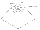
図12,図13はナーリング歯58の先端平坦面58aに、クロス溝59を形成した第2実施形態を示している。第2実施形態では、クロス溝55によってポリマーフィルム15に転写される凹部60a内に、クロス状の補強突部60dが形成される。この補強突部60dは、囲繞隆起部60b相互を補強する補強部材としても機能するので、ナーリング突起60の高さ保持効果が長期間維持されて、ナーリング突起60のヘタリ防止が図れる。
12 and 13 show a second embodiment in which a cross groove 59 is formed on the tip
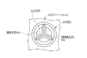
図14〜図16は、第3〜第6実施形態におけるポリマーフィルム15に形成されるナーリング突起62,64,66,68を示している。図14では、矩形状の凹部62a内に囲繞隆起部62bの対向する一対の辺に、I字状の補強突部62dを形成している。図15では円状の凹部64a内で囲繞隆起部64bに連続するように、Y字状の補強突部64dを形成している。図16では、矩形状の凹部66a内で、囲繞隆起部62bの角部に接続するようにクロス状の補強突部66dを形成している。
14-16 has shown the knurling protrusion 62,64,66,68 formed in the
これらのナーリング突起62,64,66,68をポリマーフィルム15に転写するためのナーリング歯は、図示は省略したが、図14のものは截頭四角錐(四角錐台)の先端平坦面にI字溝を形成して構成される。また、図15のものは截頭円錐(円錐台)の先端平坦面にY字溝を形成して構成される。図16のものは截頭四角錐の先端平坦面にクロス溝を形成して構成される。なお、各溝の縦断面形状は三角、台形、半円などにより構成される。このように、各種形状の補強突部62d,64d,66d,68dにより、凹部62a,64a,66a,68aや囲繞隆起部62b,64b,64b,68bのヘタリが抑えられる。
The knurling teeth for transferring these knurling protrusions 62, 64, 66, and 68 to the
なお、ナーリング歯40の形状は図8,図12に示すように、截頭四角錐状に形成されるもの以外であってもよく、半球、円柱、楕円柱、三角、五画などの多角柱や、円錐、楕円錐、多角錐の頂部を切り落としたものであってもよい。また、補強部形成凹部51も、截頭角錐以外に、円錐、楕円錘、角錐や角柱でもよい。また、補強部形成凹部51の平面形状は、矩形以外に、丸、三角、五角、楕円やその他の形状であってもよい。さらには、図12に示すように、補強部形成凹部を、囲繞隆起部間に掛け渡されるクロス溝55としたものや、図14,図15に示すように、補強部形成凹部を、囲繞隆起部間に掛け渡されるI字溝やY字溝としてもよい。
As shown in FIGS. 8 and 12, the shape of the
上記実施形態では、ナーリングローラ21,22に凸状のナーリング歯40を形成したが、これに代えて、凸状のナーリング歯40と同様の形状で、ローラ本体の外周面を凹ませて形成した凹ナーリング歯(図示省略)を設けて、ナーリングローラを形成してもよい。この場合にはポリマーフィルムの耳部に、凹ナーリング歯によって上記同様のナーリング突起を形成することができる。また、ナーリングローラには、凸ナーリング歯と凹ナーリング歯とを混在させてもよい。
In the above embodiment, the
上記実施形態では、ナーリング歯列41の一つのナーリング歯40を削除して、この削除によりナーリング歯40の密度が低くなった低密度部分(隙間42)によって、ウェブ進行方向マーク33を形成しているが、逆に、ナーリング歯列41の各ナーリング歯40の間に、例えばナーリング歯40を一つ追加して、半ピッチでナーリング歯40を配置した高密度部分をナーリング歯列41に形成し、この高密度部分によって、ウェブ進行方向マークを形成してもよい。
In the above embodiment, one
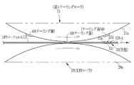
ポリマーフィルム15の幅W1は特に限定されるものではないが、600mm以上であることが好ましく、1400mm以上2500mm以下であることがより好ましい。また、ポリマーフィルム15の幅W1が2500mmよりも大きい場合にも効果がある。ポリマーフィルム15の厚さは、30μm以上200μm以下であることが好ましく、40μm以上150μm以下であることがより好ましく、40μm以上100μm以下であることがさらに好ましい。ポリマーフィルム15の長さは、2000m以上であることが好ましく、4000m以上8000m以下であることがより好ましい。また、フィルムロール19の巻取り半径は、450mm以上であることが好ましく、650mm以上920mm以下であることがより好ましい。
The width W1 of the
ポリマーフィルム15の耳部15a,15bの幅W2は特に限定されるものではないが、ポリマーフィルム15の幅W1の0.001倍以上0.01倍以下であることが好ましい。また、ナーリング30,31の幅W3は、ポリマーフィルム15の幅W1の0.1×10⁻³倍以上2.0×10⁻³倍以下であることが好ましい。ポリマーフィルム15の両側縁15eとナーリングのB方向の側縁30a,31aとの間には余白34を設けてもよいし、余白34は無くてもよい。余白34を設ける場合には、余白幅W4は、ポリマーフィルム15の幅W1の5×10⁻³倍以下であることが好ましい。
The width W2 of the ear portions 15a and 15b of the
ポリマーフィルム15の原料となるポリマーは、特に限定されない。溶液製膜方法では、例えば、セルロースアシレートや環状ポリオレフィン等が用いられる。溶融製膜方法では、例えば、セルロースアシレート、ラクトン環含有重合体、環状ポリオレフィン、ポリカーボネイト等が用いられる。なお、セルロースアシレートの詳細については、特開2005−104148号の[0140]段落から[0195]段落に記載されている。これらの記載も本発明にも適用することができる。また、溶剤及び可塑剤,劣化防止剤,紫外線吸収剤(UV剤),光学異方性コントロール剤,レターデーション制御剤,染料,マット剤,剥離剤,剥離促進剤などの添加剤についても、同じく特開2005−104148号の[0196]段落から[0516]段落に詳細に記載されている。
The polymer used as the raw material for the
次に、本発明の効果の有無を確認するために、図8に示すナーリング歯40を有するナーリングローラ21と、図8に示すナーリング歯40の先端平坦部40aに補強部形成凹部51が形成されていないナーリングローラとを用いてナーリングを付したときの経時変化によるナーリングの凹凸の減少を観察した。
Next, in order to confirm the presence or absence of the effect of the present invention, the reinforcing portion forming recess 51 is formed in the
(実施例1)
図1に示すフィルムロール製造設備10において、長さが5000m、幅が1500mm、厚みが80μmのセルロースアシレートフィルムによるフィルムロール19を製造した。ナーリングローラ21,22として、図8に示すナーリング歯40を有し、ナーリング歯40の基部における一辺の長さが250μm、基部から截頭面までの高さを500μm、補強突部の高さH1を15μm、ナーリング歯40のピッチP1を1400μmで、第1ナーリングローラ21は図5に示すマークパターンを有するものを用いた。また、第2ナーリングローラ22は図8に示すナーリング歯40を有し、これらナーリング歯40を図7に示すパターンとしたものを用いた。ナーリングローラ21,22と支持ローラ20とのニップ圧力は30Nで、各ローラ20〜22の温度は250℃とした。
Example 1
In the film
(比較例)
第1ナーリングローラとして、図8に示すナーリング歯40において、先端平坦面40aに補強部形成凹部51を有することがない平坦面を用いた以外は、実施例1と同じ条件でナーリングを付与した。なお、ナーリング歯40の形状・寸法は実施例1と同じであり、相違点は先端平坦面40aに補強部形成凹部51を有していない点である。
(Comparative example)
As the first knurling roller, knurling was applied under the same conditions as in Example 1 except that the
図10における高さH1〜H4、図11における囲繞隆起部32bの頂部稜線32eにより囲まれる面積をS1、前記補強突部32dの頂部の面積をS2としたときの面積比率(S2/S1)を求めると以下の表のようになる。なお、再評価は、ナーリングを付与したフィルム(厚み80μm)を40×20mmの矩形シートに形成し、この矩形シートを100枚重ね、この重ねた矩形シートの最上面に対して10kgの錘を載せて、矩形シートの全面に均一に圧力が掛かるようにし、10日間経過した後に、再度、各部を採寸した。
The area ratio (S2 / S1) when the height H1 to H4 in FIG. 10, the area surrounded by the
上記表からも判るように、第1実施例では、再評価後のへたり量がH3,H4で3μmであるのに対し、比較例では3倍の9μmであり、補強突起32dを有する第1実施例では、補強突起32dが無い比較例に比べて、へたり防止効果が得られていることが判る。上記の再評価結果から、本発明では、経時変化によりナーリング突起の凹凸の緩和が少なくなり、これによってフィルムロールの輸送時の擦り傷の発生が少なくなることが判る。
As can be seen from the above table, in the first example, the amount of sag after re-evaluation is 3 μm for H3 and H4, whereas in the comparative example, it is 9 μm, which is three times larger, and the first example having the reinforcing
10 フィルムロール製造設備
11 フィルム製造ライン
12 ナーリング装置
13 巻取り装置
15 ポリマーフィルム
15a,15b 耳部
20 支持ローラ
21 第1ナーリングローラ
22 第2ナーリングローラ
30 第1ナーリング
31 第2ナーリング
32 ナーリング突起
33,35 ウェブ進行方向マーク
35a Vマーク
35b Yマーク
40 ナーリング歯
41 ナーリング歯列
42 隙間
43 ナーリング歯行
50 突起
51 補強部形成凹部
55 クロス溝
60,62,64,66 ナーリング突起
DESCRIPTION OF
Claims (9)
前記ナーリング歯を、先端が平坦に突出する突起と、前記突起の先端平坦面に形成される補強部形成凹部とから構成することを特徴とするナーリングローラ。 In a knurling roller having knurling teeth for imparting knurling to the web on the outer peripheral surface of the roller body,
A knurling roller, wherein the knurling teeth are composed of a protrusion whose tip protrudes flat and a reinforcing portion forming recess formed on a flat surface of the tip of the protrusion.
請求項4記載のナーリング装置を用い、前記ポリマーフィルムの両側縁部にナーリングを形成するナーリング形成工程と、
前記ポリマーフィルムをロール状に巻き取るウェブ巻き取り工程とを含むことを特徴とするフィルムロール製造方法。 In the film roll manufacturing method of manufacturing a film roll from a continuously manufactured belt-shaped polymer film,
Using the knurling device according to claim 4, a knurling forming step of forming knurling on both side edges of the polymer film;
The film roll manufacturing method characterized by including the web winding-up process which winds up the said polymer film in roll shape.
前記ナーリング突起は、前記ポリマーフィルムの一方の面に形成される凹部と、前記凹部を囲むように突出する囲繞隆起部と、前記凹部内に突出する補強突部と、前記ポリマーフィルムの他方の面に前記凹部に対応して突出する裏面突起とを有することを特徴とする光学フィルム。 Embossing is performed in the width direction of the belt-shaped polymer film to form a protrusion row, the protrusion row is arranged at a constant pitch in the longitudinal direction of the polymer film to form a knurling, and the knurling is formed on both side edges of the polymer film. In the optical film in the part,
The knurling protrusion includes a recess formed on one surface of the polymer film, a surrounding ridge protruding to surround the recess, a reinforcing protrusion protruding into the recess, and the other surface of the polymer film. An optical film comprising a back surface protrusion protruding corresponding to the recess.
Priority Applications (3)
| Application Number | Priority Date | Filing Date | Title |
|---|---|---|---|
| JP2012031352A JP5466250B2 (en) | 2012-02-16 | 2012-02-16 | Knurling roller, apparatus, film roll manufacturing method and optical film |
| TW102103176A TWI595999B (en) | 2012-02-16 | 2013-01-28 | Knurling roller and knurling device, film roll producing method, and polymer film |
| KR1020130010390A KR20130094735A (en) | 2012-02-16 | 2013-01-30 | Knurling roller and apparatus, film roll manufacturing method, polymer film |
Applications Claiming Priority (1)
| Application Number | Priority Date | Filing Date | Title |
|---|---|---|---|
| JP2012031352A JP5466250B2 (en) | 2012-02-16 | 2012-02-16 | Knurling roller, apparatus, film roll manufacturing method and optical film |
Publications (2)
| Publication Number | Publication Date |
|---|---|
| JP2013166317A true JP2013166317A (en) | 2013-08-29 |
| JP5466250B2 JP5466250B2 (en) | 2014-04-09 |
Family
ID=49177150
Family Applications (1)
| Application Number | Title | Priority Date | Filing Date |
|---|---|---|---|
| JP2012031352A Active JP5466250B2 (en) | 2012-02-16 | 2012-02-16 | Knurling roller, apparatus, film roll manufacturing method and optical film |
Country Status (3)
| Country | Link |
|---|---|
| JP (1) | JP5466250B2 (en) |
| KR (1) | KR20130094735A (en) |
| TW (1) | TWI595999B (en) |
Cited By (5)
| Publication number | Priority date | Publication date | Assignee | Title |
|---|---|---|---|---|
| WO2016027827A1 (en) * | 2014-08-21 | 2016-02-25 | シャープ株式会社 | Mold and method for producing mold |
| JP2017032756A (en) * | 2015-07-31 | 2017-02-09 | 三菱レイヨン株式会社 | Transparent film and method for manufacturing the same |
| US20210345715A1 (en) * | 2020-05-06 | 2021-11-11 | Top Glove International Sdn. Bhd. | Embossments for thin film articles |
| KR20220160605A (en) | 2020-03-31 | 2022-12-06 | 도요보 가부시키가이샤 | Elongated resin film subjected to knurling |
| KR20240070682A (en) | 2021-10-06 | 2024-05-21 | 도요보 가부시키가이샤 | Long-length resin film with knurl processing |
Families Citing this family (1)
| Publication number | Priority date | Publication date | Assignee | Title |
|---|---|---|---|---|
| JP6407805B2 (en) * | 2015-06-24 | 2018-10-17 | 富士フイルム株式会社 | Web manufacturing method and web |
Citations (3)
| Publication number | Priority date | Publication date | Assignee | Title |
|---|---|---|---|---|
| JPH0755747B2 (en) * | 1986-09-19 | 1995-06-14 | 東レ株式会社 | Film winding method |
| US5670188A (en) * | 1994-12-19 | 1997-09-23 | Eastman Kodak Company | Apparatus for single-sided, cold mechanical knurling |
| JP2011128356A (en) * | 2009-12-17 | 2011-06-30 | Nippon Zeon Co Ltd | Protective film for polarizing plate |
Family Cites Families (5)
| Publication number | Priority date | Publication date | Assignee | Title |
|---|---|---|---|---|
| CN100519129C (en) * | 2004-05-28 | 2009-07-29 | 富士胶片株式会社 | Solution casting method for producing polymer film and suction roll for the same |
| JP4792419B2 (en) * | 2006-03-23 | 2011-10-12 | 富士フイルム株式会社 | Method for producing polymer film |
| JP2008246682A (en) * | 2007-03-29 | 2008-10-16 | Toray Ind Inc | Embossed film and embossing equipment |
| JP4982400B2 (en) * | 2008-02-04 | 2012-07-25 | 富士フイルム株式会社 | Polymer film winding method and apparatus |
| JP5684545B2 (en) * | 2009-12-14 | 2015-03-11 | 富士フイルム株式会社 | Polymer film, film roll and knurling roller |
-
2012
- 2012-02-16 JP JP2012031352A patent/JP5466250B2/en active Active
-
2013
- 2013-01-28 TW TW102103176A patent/TWI595999B/en active
- 2013-01-30 KR KR1020130010390A patent/KR20130094735A/en not_active Ceased
Patent Citations (3)
| Publication number | Priority date | Publication date | Assignee | Title |
|---|---|---|---|---|
| JPH0755747B2 (en) * | 1986-09-19 | 1995-06-14 | 東レ株式会社 | Film winding method |
| US5670188A (en) * | 1994-12-19 | 1997-09-23 | Eastman Kodak Company | Apparatus for single-sided, cold mechanical knurling |
| JP2011128356A (en) * | 2009-12-17 | 2011-06-30 | Nippon Zeon Co Ltd | Protective film for polarizing plate |
Cited By (9)
| Publication number | Priority date | Publication date | Assignee | Title |
|---|---|---|---|---|
| WO2016027827A1 (en) * | 2014-08-21 | 2016-02-25 | シャープ株式会社 | Mold and method for producing mold |
| CN106660263A (en) * | 2014-08-21 | 2017-05-10 | 夏普株式会社 | Mold and method for producing mold |
| JPWO2016027827A1 (en) * | 2014-08-21 | 2017-07-06 | シャープ株式会社 | Type |
| CN106660263B (en) * | 2014-08-21 | 2019-04-05 | 夏普株式会社 | Molds and methods of making molds |
| JP2017032756A (en) * | 2015-07-31 | 2017-02-09 | 三菱レイヨン株式会社 | Transparent film and method for manufacturing the same |
| KR20220160605A (en) | 2020-03-31 | 2022-12-06 | 도요보 가부시키가이샤 | Elongated resin film subjected to knurling |
| US20210345715A1 (en) * | 2020-05-06 | 2021-11-11 | Top Glove International Sdn. Bhd. | Embossments for thin film articles |
| US11969036B2 (en) * | 2020-05-06 | 2024-04-30 | Top Glove International Sdn. Bhd. | Embossments for thin film articles |
| KR20240070682A (en) | 2021-10-06 | 2024-05-21 | 도요보 가부시키가이샤 | Long-length resin film with knurl processing |
Also Published As
| Publication number | Publication date |
|---|---|
| JP5466250B2 (en) | 2014-04-09 |
| KR20130094735A (en) | 2013-08-26 |
| TWI595999B (en) | 2017-08-21 |
| TW201334950A (en) | 2013-09-01 |
Similar Documents
| Publication | Publication Date | Title |
|---|---|---|
| JP5466250B2 (en) | Knurling roller, apparatus, film roll manufacturing method and optical film | |
| JP6236115B2 (en) | Flexible glass roll and winding method thereof | |
| JP5056312B2 (en) | Method for producing stretched sheet and method for producing anisotropic optical sheet | |
| US9019609B2 (en) | Continuous roll of optical function film, method of manufacture of liquid crystal display element employing same, and optical function film laminating device | |
| US9019608B2 (en) | Continuous roll of optical function film, method of manufacture of liquid crystal display element employing same, and optical function film laminating device | |
| KR102597116B1 (en) | Manufacturing method of glass film with resin tape, and manufacturing method of glass film | |
| WO2011111625A1 (en) | Glass roll and method for producing the same | |
| CN106273398B (en) | Method for manufacturing web and web | |
| JP5650140B2 (en) | Knurling roller, apparatus, web roll manufacturing method and optical film | |
| JP5704759B2 (en) | Polymer film | |
| JP7031316B2 (en) | Method for manufacturing diagonally stretched film | |
| JP2013237256A (en) | Thermoplastic resin film | |
| JP2010120325A (en) | Optical film, and method of manufacturing the same | |
| JP4659384B2 (en) | Film roll | |
| JP5699320B2 (en) | Roll film base | |
| JP2015060143A (en) | Optical film and manufacturing method thereof | |
| JP2014071326A (en) | Optical sheet and display device | |
| CN104015350B (en) | Optical thin film and its manufacture method | |
| JP6393763B2 (en) | Type | |
| JP2014233868A (en) | Film laminated body in coiled form | |
| JP2014071327A (en) | Diffraction optical sheet and display device | |
| JP2016087803A (en) | Resin film roll | |
| JP2015016607A (en) | Stripe pattern correction method, photomask, and stripe pattern sheet | |
| JP2017105592A (en) | Method for manufacturing optical film | |
| JP2012218386A (en) | Elongate flexible base material with pattern |
Legal Events
| Date | Code | Title | Description |
|---|---|---|---|
| A621 | Written request for application examination |
Free format text: JAPANESE INTERMEDIATE CODE: A621 Effective date: 20130805 |
|
| A977 | Report on retrieval |
Free format text: JAPANESE INTERMEDIATE CODE: A971007 Effective date: 20131217 |
|
| TRDD | Decision of grant or rejection written | ||
| A01 | Written decision to grant a patent or to grant a registration (utility model) |
Free format text: JAPANESE INTERMEDIATE CODE: A01 Effective date: 20131225 |
|
| A61 | First payment of annual fees (during grant procedure) |
Free format text: JAPANESE INTERMEDIATE CODE: A61 Effective date: 20140123 |
|
| R150 | Certificate of patent or registration of utility model |
Ref document number: 5466250 Country of ref document: JP Free format text: JAPANESE INTERMEDIATE CODE: R150 Free format text: JAPANESE INTERMEDIATE CODE: R150 |
|
| R250 | Receipt of annual fees |
Free format text: JAPANESE INTERMEDIATE CODE: R250 |
|
| R250 | Receipt of annual fees |
Free format text: JAPANESE INTERMEDIATE CODE: R250 |
|
| R250 | Receipt of annual fees |
Free format text: JAPANESE INTERMEDIATE CODE: R250 |
|
| R250 | Receipt of annual fees |
Free format text: JAPANESE INTERMEDIATE CODE: R250 |
|
| R250 | Receipt of annual fees |
Free format text: JAPANESE INTERMEDIATE CODE: R250 |
|
| R250 | Receipt of annual fees |
Free format text: JAPANESE INTERMEDIATE CODE: R250 |
|
| R250 | Receipt of annual fees |
Free format text: JAPANESE INTERMEDIATE CODE: R250 |
|
| R250 | Receipt of annual fees |
Free format text: JAPANESE INTERMEDIATE CODE: R250 |
|
| R250 | Receipt of annual fees |
Free format text: JAPANESE INTERMEDIATE CODE: R250 |
|
| R250 | Receipt of annual fees |
Free format text: JAPANESE INTERMEDIATE CODE: R250 |