JP2013158366A - Electrode for living body, method for manufacturing the same and iontophoretic apparatus - Google Patents
Electrode for living body, method for manufacturing the same and iontophoretic apparatus Download PDFInfo
- Publication number
- JP2013158366A JP2013158366A JP2012020328A JP2012020328A JP2013158366A JP 2013158366 A JP2013158366 A JP 2013158366A JP 2012020328 A JP2012020328 A JP 2012020328A JP 2012020328 A JP2012020328 A JP 2012020328A JP 2013158366 A JP2013158366 A JP 2013158366A
- Authority
- JP
- Japan
- Prior art keywords
- electrode
- forming
- flexible substrate
- film
- adhesive layer
- Prior art date
- Legal status (The legal status is an assumption and is not a legal conclusion. Google has not performed a legal analysis and makes no representation as to the accuracy of the status listed.)
- Pending
Links
Images
Landscapes
- Electrotherapy Devices (AREA)
Abstract
【課題】コスト低減を実現できると共に、剥離等の問題がなくパターン精度が良好なイオントフォレシス等に用いる生体用電極、及びその製造方法を提供する。
【解決手段】フレキシブル基材2と、フレキシブル基材上に設けられた厚さ10nm以上300nm以下の第1電極11と、第1電極が設けられたフレキシブル基材の同一面Sに隣接して設けられ、厚さ5μm以上50μm以下の金属箔であって、第1電極との間で起電力が発生する電位差を持つ第2電極21と、第1電極及び第2電極の一方又は両方から延びて重なる接続配線7と、接続配線を覆う絶縁膜4とを有し、第2電極が導電性粘着剤層20を介して貼り合わされている生体用電極1による。このとき、第1電極が貴金属であり、第2電極が亜鉛箔又は酸化亜鉛箔であることが好ましい。フレキシブル基材と、第1電極及び導電性粘着剤20の一方又は両方との間に、プライマー層3が設けられていることが好ましい。
【選択図】図1Provided are a biological electrode used for iontophoresis and the like, which can realize cost reduction, has no problem of peeling, etc., and has good pattern accuracy, and a manufacturing method thereof.
A flexible substrate, a first electrode having a thickness of not less than 10 nm and not more than 300 nm provided on the flexible substrate, and adjacent to the same surface S of the flexible substrate provided with the first electrode. A metal foil having a thickness of 5 μm or more and 50 μm or less and extending from one or both of the second electrode 21 having a potential difference that generates an electromotive force with the first electrode and the first electrode and the second electrode. The living body electrode 1 includes the overlapping connection wiring 7 and the insulating film 4 that covers the connection wiring, and the second electrode is bonded to the conductive adhesive layer 20. At this time, it is preferable that the first electrode is a noble metal and the second electrode is a zinc foil or a zinc oxide foil. It is preferable that the primer layer 3 is provided between the flexible substrate and one or both of the first electrode and the conductive adhesive 20.
[Selection] Figure 1
Description
本発明は、イオントフォレシスに用いる生体用電極、その製造方法及びイオントフォレシス装置に関する。 The present invention relates to a biological electrode used for iontophoresis, a method for producing the same, and an iontophoresis device.
イオントフォレシス(IONTOPHORESIS)は、電気エネルギーを利用して、主にイオン性薬剤の生体膜への透過を促進させる方法であり、薬剤の経皮吸収の促進を目的に利用されている。具体的には、薄型電極と導電性電極とが電気的に接続されたシートを、イオン性薬剤を介して皮膚に貼り合わせ、電極間に微細電流を流して、電荷を持つイオン性薬剤を皮膚中に浸透させる技術である。 Iontophoresis (IONTOPHORESIS) is a method that mainly promotes permeation of ionic drugs through biological membranes using electric energy, and is used for the purpose of promoting percutaneous absorption of drugs. Specifically, a sheet in which a thin electrode and a conductive electrode are electrically connected is bonded to the skin via an ionic agent, and a fine current is passed between the electrodes to cause the charged ionic agent to be attached to the skin. It is a technology that penetrates inside.
こうしたイオントフォレシス装置として、特許文献1には、生物の体表の異なる二か所の表面電位差を利用すること、及び体表面の電解質と電極との間のイオン化傾向を利用することにより、発電した電力により装置を小型化した有効成分を体表面から体内に導入するイオン導入装置が提案されている。この技術によれば、コストが安価で使い方が容易で安全で効果が高く小型で携帯可能で使い捨ても可能なイオン導入装置を提供できるとされている。
As such an iontophoresis device,
また、特許文献2には、複数の自給式の直列接続されたガルバニ電源を設けられる経皮的イオン導入による治療薬剤伝達システムであって、各々が酸化可能種と還元可能種を含む複数のガルバニ電源を有し、前記複数ガルバニ電源のうちの少なくとも1つが治療薬剤のための第1の伝達チャンバと接触した酸化可能種、治療薬剤のための第2の伝達チャンバと接触した還元可能種をさらに含む活性薬剤電源であり、前記経皮的イオン導入による伝達システムの全体的なガルバニ電位が前記活性薬剤ガルバニ電源の合計となるように前記複数ガルバニ電源を直列接続する導体を有する治療薬剤伝達システムが提案されている。さらに、ガルバニ電源のうち1つ又は複数がスクリーン印刷された電極を有することが記載され、酸化可能種がMgとZnから選択され、還元可能種がAgClであることが記載されている。
また、特許文献3では、形状可変型の基板、前記基板と接触する第1導電層、前記第1導電層の一部と接触する第1電極層、前記基板と接触し、第1導電層と同一平面上に位置する第2導電層、前記第2導電層と接触する集電体、前記第2導電層及び集電体と接触する導電性接着剤、前記集電体と接触し、前記第1電極層と反対極性の第2電極層、前記第1電極層と第2電極層の間に位置するイオン伝導性高分子電解質、及び前記イオン伝導性高分子電解質を密封する接着剤を含む電池一体型イオントフォレシスパッチが提案されている。この技術によれば、イオントフォレシスパッチと電池を一体化して製造生産性を向上させ、電流抵抗を最小化して高効率を提供できるとされている。
In
また、特許文献4には、低周波治療器等に用いられる生体用電極が提案されており、その生体用電極を構成する導電層を、導電性の炭素微粒子及び銀微粒子と樹脂バインダーとを含む導電性インクや、銀を主体とする導電性インクでスクリーン印刷して形成することが記載されている。
また、特許文献5には、低周波治療器やイオントフォレシス装置を構成する生体用電極が提案されており、その生体用電極を構成する厚さ2μm〜35μmの導電層を、銀、銀/塩化銀、ニッケル等の金属粒子等と樹脂バインダーとを含む導電性インクをスクリーン印刷等して形成することが記載されている。
上記した従来の生体用電極では、厚さ5μm〜15μm前後の導電層を、金属粒子と樹脂バインダーとを含む導電性インクをスクリーン印刷して形成していた。しかしながら、こうした厚い導電層を、フレキシブルな薄いプラスチック基材上に形成すると、導電層の形成後に導電性を得るためのアニール工程(例えば120℃、15分など)の加熱収縮等によってプラスチック基材が歪んだり変形したりするという問題があった。また、生体用電極は使い捨て型であるため、コストの低減が要求されていた。 In the above-described conventional biomedical electrode, a conductive layer having a thickness of about 5 μm to 15 μm is formed by screen-printing a conductive ink containing metal particles and a resin binder. However, when such a thick conductive layer is formed on a flexible thin plastic substrate, the plastic substrate is formed by heat shrinkage or the like in an annealing process (for example, 120 ° C., 15 minutes) for obtaining conductivity after the formation of the conductive layer. There was a problem of distortion and deformation. Moreover, since the biomedical electrode is a disposable type, cost reduction has been demanded.
また、導電層の形成方法として金属箔を貼り合わせて行う方法も考えられるが、ハンドリングの良い一般的な金属箔は10μm以上の厚さであり、例えば耐食性と電気化学的安定性を備えた貴金属箔を用いる場合には、コスト低減を図れないという問題があった。 In addition, a method of forming a conductive layer by laminating a metal foil is also conceivable, but a general metal foil with good handling has a thickness of 10 μm or more, for example, a noble metal having corrosion resistance and electrochemical stability. When foil is used, there is a problem that cost cannot be reduced.
本発明は、上記課題を解決するためになされたものであって、その目的は、コスト低減を実現できると共に、剥離等の問題がなくパターン精度が良好なイオントフォレシス等に用いる生体用電極、及びその製造方法を提供することにある。また、本発明の他の目的は、そうした生体用電極を有したイオントフォレシス装置を提供することにある。 The present invention has been made in order to solve the above-mentioned problems, and its purpose is to realize a reduction in cost and a biological electrode used for iontophoresis or the like having no problem of peeling and having good pattern accuracy, And a manufacturing method thereof. Another object of the present invention is to provide an iontophoresis device having such a biological electrode.
(1)上記課題を解決するための本発明に係る生体用電極は、フレキシブル基材と、該フレキシブル基材上に設けられた厚さ10nm以上300nm以下の第1電極と、該第1電極が設けられた前記フレキシブル基材の同一面に隣接して設けられ、厚さ5μm以上50μm以下の金属箔であって、前記第1電極との間で起電力が発生する電位差を持つ第2電極と、前記第1電極及び前記第2電極の一方又は両方から延びて重なる接続配線と、該接続配線を覆う絶縁膜と、を有し、前記第2電極は、導電性粘着剤層を介して貼り合わされていることを特徴とする。 (1) The biomedical electrode according to the present invention for solving the above-mentioned problems is a flexible base material, a first electrode having a thickness of 10 nm to 300 nm that is provided on the flexible base material, and the first electrode is A metal foil having a thickness of 5 μm or more and 50 μm or less provided adjacent to the same surface of the provided flexible substrate, and having a potential difference that generates an electromotive force with the first electrode; A connection wiring extending from and overlapping one or both of the first electrode and the second electrode, and an insulating film covering the connection wiring, wherein the second electrode is bonded via a conductive adhesive layer. It is characterized by being combined.
この発明によれば、第1電極を蒸着膜の厚さ範囲に薄膜化し、第2電極を金属箔としたので、例えば第1電極を貴金属材料で形成し、第2電極を廉価な金属箔で形成することにより、電極材料のコストを大幅に削減することができる。また、第1電極及び第2電極の一方又は両方から延びて重なる接続配線を覆うように絶縁膜を設けたので、薬剤ジェルを介して皮膚にフレキシブルに貼り合わせた場合であっても、両電極の接続信頼性を維持することができ、信頼性が高く、接触抵抗も低い生体用電極とすることができる。また、第1電極と第2電極との接続配線は、第1電極と第2電極の形成時に一括形成できるので、製造のし易い構造形態を有する生体用電極を提供できる。 According to this invention, since the first electrode is thinned to the thickness range of the vapor deposition film and the second electrode is made of metal foil, for example, the first electrode is made of a noble metal material and the second electrode is made of inexpensive metal foil. By forming, the cost of the electrode material can be greatly reduced. In addition, since the insulating film is provided so as to cover the overlapping connection wiring extending from one or both of the first electrode and the second electrode, both electrodes can be used even when they are flexibly bonded to the skin through the drug gel. Connection reliability can be maintained, and it is possible to provide a biological electrode with high reliability and low contact resistance. In addition, since the connection wiring between the first electrode and the second electrode can be formed at the same time when the first electrode and the second electrode are formed, it is possible to provide a biomedical electrode having a structure that is easy to manufacture.
本発明に係る生体用電極において、前記第1電極が貴金属であり、前記第2電極が亜鉛箔又は酸化亜鉛箔である。 In the biological electrode according to the present invention, the first electrode is a noble metal, and the second electrode is a zinc foil or a zinc oxide foil.
この発明によれば、第1電極を貴金属で形成し、第2電極を低価格な亜鉛箔又は酸化亜鉛箔で形成したので、起電力が発生する電位差を持たせることができ、且つコスト低減を実現できる。 According to this invention, since the first electrode is formed of a noble metal and the second electrode is formed of a low-cost zinc foil or zinc oxide foil, it is possible to have a potential difference that generates an electromotive force and to reduce costs. realizable.
本発明に係る生体用電極において、前記貴金属が銀である。 In the biomedical electrode according to the present invention, the noble metal is silver.
この発明によれば、貴金属の中でも低コストで電気化学的に安定な銀を電極材料として用いたので、生体用電極のコスト低減と信頼性の点で有利である。 According to this invention, among the noble metals, low-cost and electrochemically stable silver is used as the electrode material, which is advantageous in terms of cost reduction and reliability of the biomedical electrode.
本発明に係る生体用電極において、前記フレキシブル基材と、前記第1電極及び前記導電性粘着剤層の一方又は両方との間に、プライマー層が設けられている。 In the biological electrode according to the present invention, a primer layer is provided between the flexible substrate and one or both of the first electrode and the conductive adhesive layer.
この発明によれば、プライマー層が、フレキシブル基材上への第1電極及び第2電極の下層として設けられている導電性粘着剤層の一方又は両方との密着性を高めている。 According to this invention, the primer layer is improving the adhesiveness with the one or both of the electroconductive adhesive layer provided as a lower layer of the 1st electrode and 2nd electrode on a flexible base material.
(2)上記課題を解決するための本発明に係る生体用電極の製造方法は、フレキシブル基材を準備する工程と、前記フレキシブル基材上に厚さ10nm以上300nm以下の金属蒸着膜からなる第1電極を形成する工程と、前記第1電極が形成される前記フレキシブル基材の同一面に隣接して設けられた導電性粘着剤層を形成する工程と、前記導電性粘着剤層上に厚さ5μm以上50μm以下で、前記第1電極との間で起電力が発生する電位差を持つ金属箔からなる第2電極を形成する工程と、前記第1電極の形成工程及び前記第2電極の形成工程で該第1電極及び該第2電極の一方又は両方から延びた接続配線を重ねる工程と、前記接続配線を絶縁膜で覆う工程とを有することを特徴とする。 (2) The manufacturing method of the biomedical electrode according to the present invention for solving the above-described problems includes a step of preparing a flexible base material and a metal vapor deposition film having a thickness of 10 nm to 300 nm on the flexible base material. A step of forming one electrode, a step of forming a conductive pressure-sensitive adhesive layer provided adjacent to the same surface of the flexible substrate on which the first electrode is formed, and a thickness on the conductive pressure-sensitive adhesive layer Forming a second electrode made of a metal foil having a potential difference of 5 μm or more and 50 μm or less and generating an electromotive force with the first electrode, forming the first electrode, and forming the second electrode The method includes a step of stacking connection wires extending from one or both of the first electrode and the second electrode, and a step of covering the connection wires with an insulating film.
この発明によれば、第1電極を蒸着膜の厚さ範囲で形成し、第2電極として金属箔を導電性粘着剤層上に貼り合わせたので、例えば第1電極を貴金属材料で形成し、第2電極を廉価な金属箔で形成することにより、電極材料のコストを大幅に削減することができる。また、第1電極及び第2電極の一方又は両方から延びて重なる接続配線を覆うように絶縁膜を設けたので、薬剤ジェルを介して皮膚にフレキシブルに貼り合わせた場合であっても、両電極の接続信頼性を維持することができ、信頼性が高く、接触抵抗も低い生体用電極とすることができる。また、第1電極と第2電極との接続配線は、第1電極と第2電極の形成時に一括形成できるので、製造のし易い構造形態を有する生体用電極を提供できる。 According to the present invention, the first electrode is formed in the thickness range of the vapor deposition film, and the metal foil is bonded on the conductive adhesive layer as the second electrode. For example, the first electrode is formed of a noble metal material, By forming the second electrode with an inexpensive metal foil, the cost of the electrode material can be greatly reduced. In addition, since the insulating film is provided so as to cover the overlapping connection wiring extending from one or both of the first electrode and the second electrode, both electrodes can be used even when they are flexibly bonded to the skin through the drug gel. Connection reliability can be maintained, and it is possible to provide a biological electrode with high reliability and low contact resistance. In addition, since the connection wiring between the first electrode and the second electrode can be formed at the same time when the first electrode and the second electrode are formed, it is possible to provide a biomedical electrode having a structure that is easy to manufacture.
本発明に係る生体用電極の製造方法において、前記フレキシブル基材の準備工程と前記第1電極の形成工程との間に、プライマー層を形成する工程を有する。 The manufacturing method of the biomedical electrode according to the present invention includes a step of forming a primer layer between the step of preparing the flexible substrate and the step of forming the first electrode.
この発明によれば、フレキシブル基材の準備工程と第1電極(最初に形成する電極)の形成工程との間にプライマー層を形成する工程を有するので、形成されたプライマー層は、金属蒸着膜である第1電極との密着性、第2電極の金属箔を貼り合わせる導電性粘着剤層との密着性、及びその金属蒸着膜をパターニングするためのリフトオフ用膜との密着性、を向上させることができる。その結果、金属蒸着膜を精度よくリフトオフして所定パターンの電極にパターニングすることができる。 According to this invention, since it has the process of forming a primer layer between the preparation process of a flexible base material, and the formation process of a 1st electrode (electrode formed initially), the formed primer layer is a metal vapor deposition film | membrane. The adhesion with the first electrode, the adhesion with the conductive adhesive layer to which the metal foil of the second electrode is bonded, and the adhesion with the lift-off film for patterning the metal deposition film are improved. be able to. As a result, the metal vapor deposition film can be accurately lifted off and patterned into a predetermined pattern of electrodes.
本発明に係る生体用電極の製造方法において、前記プライマー層の形成工程と前記第1電極の形成工程との間に、水溶性樹脂からなるリフトオフ用膜を形成する工程を有する。 In the method for manufacturing a biomedical electrode according to the present invention, a lift-off film made of a water-soluble resin is formed between the primer layer forming step and the first electrode forming step.
この発明によれば、プライマー層の形成工程と第1電極(最初に形成する電極)の形成工程との間に、水溶性樹脂からなるリフトオフ用膜を形成する工程を有するので、形成されたリフトオフ用膜は、金属蒸着膜からなる電極をパターニングするためのリフトオフ用膜として作用し、しかもそのリフトオフ用膜はその下に設けられたプライマー層に密着良く設けられている。その結果、リフトオフ用膜は、金属蒸着膜を精度よくリフトオフするまでプライマー層上に密着良く保持されるので、所定パターンの電極を寸法精度よく形成することができる。なお、水溶性樹脂からなるリフトオフ用膜は、水洗によって洗い流すことができ、そのリフトオフ用膜上に設けられた金属蒸着膜を容易にリフトオフすることができる。 According to this invention, since there is a step of forming a lift-off film made of a water-soluble resin between the step of forming the primer layer and the step of forming the first electrode (first electrode to be formed), the lift-off formed The working film acts as a lift-off film for patterning an electrode made of a metal vapor-deposited film, and the lift-off film is provided in close contact with the primer layer provided therebelow. As a result, the lift-off film is held in close contact with the primer layer until the metal vapor-deposited film is lifted off with high precision, so that electrodes of a predetermined pattern can be formed with high dimensional precision. The lift-off film made of a water-soluble resin can be washed away with water, and the metal vapor deposition film provided on the lift-off film can be easily lifted off.
(3)上記課題を解決するための本発明に係るイオントフォレシス装置は、上記本発明に係る生体用電極を有し、該生体用電極を構成する第1電極及び第2電極を覆うように薬剤ジェルが設けられることを特徴とする。 (3) An iontophoresis device according to the present invention for solving the above-described problems has the biological electrode according to the present invention, and covers the first electrode and the second electrode constituting the biological electrode. A drug gel is provided.
この発明によれば、第1電極を蒸着膜の厚さ範囲で形成し、第2電極として金属箔を導電性粘着剤層上に貼り合わせてなる生体用電極を有するので、使い捨て型の生体用電極を構成する金属電極材料の使用量を必要最小限に抑えることができ、イオントフォレシス装置のコスト低減を図ることができる。なお、このイオントフォレシス装置は、生体用電極を構成する第1電極と第2電極を覆うように薬剤ジェルが設けられ、その薬剤ジェルの側が皮膚に貼り合わされて使用される。 According to the present invention, the first electrode is formed within the thickness range of the vapor deposition film, and the second electrode has the biomedical electrode formed by bonding the metal foil on the conductive adhesive layer. The usage amount of the metal electrode material constituting the electrode can be minimized, and the cost of the iontophoresis device can be reduced. In this iontophoresis device, a drug gel is provided so as to cover the first electrode and the second electrode constituting the living body electrode, and the side of the drug gel is bonded to the skin for use.
本発明に係る生体用電極及びその製造方法によれば、例えば第1電極を貴金属材料で形成し、第2電極を廉価な金属箔で形成することにより、電極材料のコストを大幅に削減することができる。また、第1電極及び第2電極の一方又は両方から延びて重なる接続配線を覆うように絶縁膜を設けたので、薬剤ジェルを介して皮膚にフレキシブルに貼り合わせた場合であっても、両電極の接続信頼性を維持することができ、信頼性が高く、接触抵抗も低い生体用電極とすることができる。また、第1電極と第2電極との接続配線は、第1電極と第2電極の形成時に一括形成できるので、製造のし易い構造形態を有する生体用電極を提供できる。 According to the living body electrode and the manufacturing method thereof according to the present invention, for example, the first electrode is formed of a noble metal material, and the second electrode is formed of an inexpensive metal foil, thereby significantly reducing the cost of the electrode material. Can do. In addition, since the insulating film is provided so as to cover the overlapping connection wiring extending from one or both of the first electrode and the second electrode, both electrodes can be used even when they are flexibly bonded to the skin through the drug gel. Connection reliability can be maintained, and it is possible to provide a biological electrode with high reliability and low contact resistance. In addition, since the connection wiring between the first electrode and the second electrode can be formed at the same time when the first electrode and the second electrode are formed, it is possible to provide a biomedical electrode having a structure that is easy to manufacture.
本発明に係る生体用電極、その製造方法及びイオントフォレシス装置について、図面を参照しながら説明する。なお、本発明は、その技術的思想を含む範囲内で以下の形態に限定されない。 A biological electrode, a production method thereof, and an iontophoresis device according to the present invention will be described with reference to the drawings. In addition, this invention is not limited to the following forms within the range including the technical idea.
[生体用電極及びその製造方法]
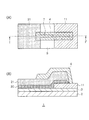
本発明に係る生体用電極1は、図1に示すように、フレキシブル基材2と、フレキシブル基材2上に設けられた厚さ10nm以上300nm以下の第1電極11と、第1電極11が設けられたフレキシブル基材2の同一面Sに隣接して設けられ、厚さ5μm以上50μm以下の金属箔であって、第1電極11との間で起電力が発生する電位差を持つ第2電極21と、第1電極11及び前記第2電極21の一方又は両方から延びて重なる接続配線7と、接続配線7を覆う絶縁膜4とを有し、第2電極21が導電性粘着剤層20を介して貼り合わされていることに特徴がある。
[Biological electrode and method for producing the same]
As shown in FIG. 1, the
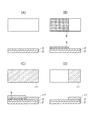
こうした生体用電極1は、図3及び図4に示すように、フレキシブル基材2を準備する工程と、フレキシブル基材2上に厚さ10nm以上200nm以下の金属蒸着膜11’からなる第1電極11を形成する工程と、フレキシブル基材2を準備する工程と、フレキシブル基材2上に厚さ10nm以上200nm以下の金属蒸着膜11’からなる第1電極11を形成する工程と、第1電極11が形成されるフレキシブル基材2の同一面Sに隣接して設けられた導電性粘着剤層20を形成する工程と、導電性粘着剤層20上に厚さ5μm以上50μm以下で、第1電極11との間で起電力が発生する電位差を持つ金属箔からなる第2電極21を形成する工程と、第1電極11の形成工程及び第2電極21の形成工程で第1電極11及び第2電極21の一方又は両方から延びた接続配線7を重ねる工程と、接続配線7を絶縁膜4で覆う工程とを有する方法で製造される。
As shown in FIGS. 3 and 4, the
なお、フレキシブル基材2の準備工程と第1電極11の形成工程との間に、プライマー層3の形成工程が設けられていることが好ましい。また、プライマー層3の形成工程と第1電極11の形成工程との間に、リフトオフ用膜8の形成工程が設けられていることが好ましい。
In addition, it is preferable that the formation process of the
こうした生体用電極1は、第1電極11を蒸着膜の厚さ範囲で形成し、第2電極21として金属箔を導電性粘着剤層20上に貼り合わせたので、例えば第1電極11を貴金属材料で形成し、第2電極21を廉価な金属箔で形成することにより、電極材料のコストを大幅に削減することができる。また、第1電極11及び第2電極21の一方又は両方から延びて重なる接続配線7を覆うように絶縁膜4を設けたので、薬剤ジェル5を介して皮膚にフレキシブルに貼り合わせた場合であっても、両電極11,21の接続信頼性を維持することができ、信頼性が高く、接触抵抗も低い生体用電極1とすることができる。また、第1電極11と第2電極21との接続配線7は、第1電極11と第2電極21の形成時に一括形成できるので、製造のし易い構造形態を有する生体用電極1を提供できる。
In such a
本願明細書において、「上に」とは、そのものの上に直に又は他の層を介して設けられていることを意味し、「直上に」とは、そのものの上に直接設けられている場合を意味する。「覆う」とは、そのものの上に設けられるとともに、そのものの周りにも設けられていることを意味する。 In this specification, “on” means being provided directly on itself or via another layer, and “on” is directly provided on itself. Means the case. "Covering" means being provided on itself and around it.
以下、本発明に係る生体用電極1の構成について説明しつつ、各工程も併せて説明する。
Hereinafter, while explaining the configuration of the
(フレキシブル基材)
フレキシブル基材2は、フレキシブルである絶縁性の基材であれば特に限定されず、プラスチックフィルムや紙等を用いることができる。フレキシブル基材2を用いることにより、人や動物の体の表面形態に追従した態様で生体用電極1を貼り付けることができる。プラスチックフィルムの例としては、ポリエチレン、ポリプロピレン、ポリエチレンテレフタレート、ポリエチレンナフタレート、ポリメタクリレート、ポリメチルメタクリレート、ポリメチルアクリレート、ポリエステル、ポリカーボネート等の樹脂フィルムを好ましく挙げることができる。中でも、ポリエチレンテレフタレート、ポリプロピレン系合成紙等が好ましい。なお、ポリプロピレン系合成紙は、ユポとは、ポリプロピレンを主原料とするフィルム合成紙であり、例えばユポ(登録商標)を挙げることができる。
(Flexible substrate)
The
プラスチックフィルム以外のものとしては、アート紙、不織布及びシリコンゴム等を挙げることができる。なお、不織布等のような隙間の空いている薄い紙は、目詰め材等で隙間を埋めて用いることが好ましい。 Examples of materials other than plastic films include art paper, non-woven fabric, and silicon rubber. In addition, it is preferable to use a thin paper with a gap, such as a nonwoven fabric, with a gap filled with a filling material or the like.
フレキシブル基材2の厚さはその材質によっても異なり、一概には言えないが、プラスチックフィルムの場合は、通常、3μm以上200μm以下のものを好ましく用いることができる。また、ユポ(登録商標)、アート紙、不織布等では、100μm以上2000μm以下のものを好ましく用いることができる。本発明で用いるフレキシブル基材2の厚さは薄いが、後述する第1電極11や第2電極21等を形成した後であっても変形が生じにくいという利点がある。その理由は、第1電極11を蒸着によって成膜し、第2電極21を金属箔の貼り合わせによって形成するので、成膜時に加熱条件が厳しくなく、従来のように金属材料と樹脂バインダーとを含む導電性材料で第1電極11や第2電極21を形成する場合の加熱等によってフレキシブル基材2が変形するという問題が生じない。なお、フレキシブル基材2の形状は、所定の大きさの枚葉形状であってもよいし、ロール状に巻かれた長尺シート基材であってもよい。
The thickness of the
(プライマー層)
プライマー層3は、図1に示すように、フレキシブル基材2上に好ましく設けられる。このプライマー層3は、図3に示すように、第1電極11の下地層としてフレキシブル基材2上に設けられ、金属蒸着膜11’をパターニングするためのリフトオフ用のリフトオフ用膜8との密着性を向上させることができる。さらに、プライマー層3上に金属蒸着膜11’が形成されることにより、形成された金属蒸着膜11’及び導電性粘着剤層20の密着性を向上させて金属蒸着膜11’及び導電性粘着剤層20の剥離等を防いで、金属蒸着膜11’を精度よくパターニングし、導電性粘着剤層20上に金属箔を精度よく貼り合わせて、所定パターンの第1電極11及び第2電極21を形成するのに極めて効果的である。
(Primer layer)
As shown in FIG. 1, the
プライマー層3の形成工程は、図3(A)に示すように、フレキシブル基材2の準備工程と、後述の第1電極11の形成工程との間に設けられる。
As shown in FIG. 3A, the formation process of the
プライマー層3は、フレキシブル基材2上の全面に設けてもよいし、金属蒸着膜11’及び導電性粘着剤層20を形成する領域にのみ設けてもよい。プライマー層3の形成材料は、金属蒸着膜11’及び導電性粘着剤層20の密着性を高めることができる一般的なプライマー樹脂であれば特に限定されない。例えば、二液反応型のプライマー樹脂を各種の塗布方法で塗布し、所定温度で反応させてプライマー層3を形成する。プライマー層3の厚さは特に限定されないが、例えば、1μm以上5μm以下とすることができる。
The
(リフトオフ用膜)
リフトオフ用膜8は、図3(B)に示すように、プライマー層3上にパターン形成されることが好ましく、その上に設けられる第1電極11をリフトオフして所定のパターンに形成することができる。このリフトオフ用膜8をネガ型感光性樹脂組成物で形成する場合は、その感光性樹脂組成物を成膜した後に露光マスクを介して露光され、光が当たらなかった部分が現像液で剥離し易くなり、光が当たった部分が残る。残った膜が、その後に成膜される金属蒸着膜11’をパターニングするためのリフトオフ用膜となる。そして、リフトオフ用膜8は、その下に設けられたプライマー層3に密着良く設けられる。そのため、リフトオフ用膜8は、水等の溶媒洗浄で剥離されるまでの間はプライマー層3上で剥離することなく密着良く保持されているので、図3(C)に示すように、その後に金属蒸着膜11’が成膜され、リフトオフ用膜8上の金属蒸着膜11’のリフトオフを精度よく行なわせることができる。その結果、所定パターンの第1電極11を精度よく形成することができる。なお、水溶性樹脂からなるリフトオフ用膜8は、水洗によって洗い流すことができ、そのリフトオフ用膜8上に設けられた金属蒸着膜11’を容易にリフトオフすることができる。
(Lift-off membrane)
As shown in FIG. 3B, the lift-
リフトオフ用膜8の形成工程は、図3(B)〜図3(D)に示すように、プライマー層3の形成工程と、後述する第1電極11の形成工程との間に設けられて、リフトオフ用膜8を形成する工程である。
As shown in FIGS. 3B to 3D, the formation process of the lift-
リフトオフ用膜8は、フレキシブル基材2上、又はプライマー層3が設けられている場合にはそのプライマー層3上に設けられる。また、リフトオフ用膜8は、全面に設けてもよいし、所定の領域に設けてもよいが、最終的に金属蒸着膜11’をリフトオフする領域に残すようにパターニングする。リフトオフ用膜8の形成材料は、一般的には「抜きプライマー」と呼ばれ、溶媒で溶解する樹脂が用いられる。例えば、水洗浄でリフトオフ用膜8上に設けられた金属蒸着膜11’ごとリフトオフすることができる水溶性樹脂が好ましく用いられる。例えば、水溶性ビニル樹脂、水溶性酢酸ビニル系樹脂等を挙げることができる。洗浄水としては、中和水、アルカリ性水、酸性水等を、その水溶性樹脂に応じて任意に選択することができる。
The lift-
リフトオフ用膜8は、そうした感光性樹脂組成物である水溶性樹脂を各種の塗布方法で塗布し、所定温度を加えてリフトオフ用膜8を形成する。リフトオフ用膜8の厚さは特に限定されないが、例えば、1μm以上5μm以下とすることができる。
The lift-
(第1電極)
第1電極11は、厚さ10nm以上300nm以下の範囲内でフレキシブル基材2上又はプライマー層3上に設けられる。第1電極11は、第2電極21との間で起電力が発生する電位差を持つものであればよく、第2電極21の種類に応じて各種の構成材料を適用できる。後述する第2電極21が例えば亜鉛箔又は酸化亜鉛箔である場合は、第1電極11は、銀、金、銅、パラジウム、ロジウム、又はそれらの合金であることが好ましい。中でも、貴金属、価格等の観点から銀電極であることが好ましい。銀電極は、例えば塩化物イオンを含む薬剤ジェル5に接触した場合であっても安定した電極特性を有するとともに、第2電極21を好ましく構成する亜鉛箔又は酸化亜鉛箔等との間で起電力を生じるので、自己発電タイプのイオントフォレシス装置31を安定した状態で実現できる。
(First electrode)
The
第1電極11の形成は、図3(C)(D)に示すように、予めリフトオフ用膜8が設けられたフレキシブル基材2上又はプライマー層3上に厚さ10nm以上300nm以下の範囲内の金属蒸着膜11’からなる第1電極11を形成する。第1電極11は、成膜された金属蒸着膜11’をパターニングして形成される。そのパターニングは、リフトオフ用膜8上に設けられた金属蒸着膜11’が、そのリフトオフ用膜8ごとリフトオフされることにより行われる。すなわち、リフトオフ用膜8上に形成されない金属蒸着膜11’が残ることにより、所定のパターンにパターニングされる。
As shown in FIGS. 3C and 3D, the
上記した厚さ範囲の金属蒸着膜11’は、従来のように樹脂バインダーを含む材料で金属電極を形成した場合の厚さ(例えば5μm〜15μm前後)に比べて、薄い第1電極11を形成でき、電極材料のコストを大幅に削減することができる。特に材料単価が高い銀、金、パラジウム等の金属では、その効果が大きい。
The metal
金属蒸着膜11’は、一般的な真空蒸着によって成膜できる。圧力、温度、蒸発原料等の成膜条件は、成膜する金属種によって任意に設定することができる。こうした真空蒸着による例えば銀電極の形成は、フレキシブル基材2に対する熱負荷が低減されるので、薄いフレキシブル基材2に「しわ」や「歪み」を生じさせない。また、従来のような樹脂バインダーを含む材料で銀電極を形成するのではなく、樹脂バインダーを含まない銀電極であるので、銀電極の抵抗値もより低くなるという利点がある。
The
第1電極11の平面視形状は、例えば図1に示すように、四角形等の角形であってもよいし、円形や楕円形であってもよいし、それらが組み合わされた形状であってもよい。また、図1に示すような一様なベタ状であってもよいし、例えば複数の窓部を有する第1電極(図示しない)としてもよいし、メッシュ部を有する第1電極(図示しない)としてもよい。このように、金属電極自体をベタ電極ではなく、窓部やメッシュ部を有するように形成することにより、その後に第1電極上に設けられる薬剤ジェル5の保持性を高めることができ、薬剤ジェル5の生体膜への透過をより促進させることができる。なお、窓部の大きさやメッシュ部の開口の大きさは、任意に設計することができる。
For example, as shown in FIG. 1, the
第1電極11は、図2に示すように、配線6を介して第2電極21に接続されている。第1電極11と第2電極21との間で起電力が生じるので、配線することにより、自己発電回路となり、自己発電型のイオントフォレシス装置31を構成できる。
As shown in FIG. 2, the
(導電性粘着剤層)
導電性粘着剤層20は、第1電極11が形成されるフレキシブル基材2の同一面Sに隣接して設けられる。導電性粘着剤層20はその後に第2電極21である金属箔が、その導電性粘着剤層20と同じ形状で貼り合わされるので、第2電極21を設ける位置に設けられている。
(Conductive adhesive layer)
The conductive
導電性粘着剤層20の形成材料は、例えば、カーボン系粘着剤、ニッケル系粘着剤等の導電性の粘着材料を用いることができる。導電性粘着剤層20は、こうした粘着材料を塗布した後、パターニングして形成される。パターニングは各種の方法で行うことができ、例えば粘着材料が感光性樹脂組成物である場合には、露光、現像を行って所定パターンの導電性粘着剤層20を形成することができる。また、粘着材料を塗布する前に、上記したリフトオフ用膜8を所定パターンで形成し、その後に導電性粘着剤層20を全面に形成した後、そのリフトオフ用膜8で不要な部分をリフトオフして所定のパターンの導電性粘着剤層20を形成することもできる。
As a material for forming the conductive pressure-
導電性粘着剤層20は、プライマー層3上に設けられるので、プライマー層3上に密着良く形成されている。そのため、その後、導電性粘着剤層20上に金属箔が貼り合わされて第2電極21を構成する場合に、導電性粘着剤層20が剥がれることがなく、密着信頼性に優れた第2電極21を形成することができるという利点がある。導電性粘着剤層20のシート抵抗値は、1Ω/□以下が好ましく用いることができる。なお、導電性粘着剤層20の厚さは上記シート抵抗値以下を満たせば特に限定されないが、例えば、10μm以上200μm以下とすることができる。
Since the conductive
(第2電極)
第2電極21は、厚さ5μm以上50μm以下の範囲内で、導電性粘着剤層20上に設けられる。導電性粘着剤層20上に設けられた第2電極21は、第1電極11が設けられたフレキシブル基材2上又はプライマー層3上の同一面Sに隣接して設けられていることになる。第2電極21も、第1電極11と同様、第1電極11との間で起電力が発生する電位差を持つものであればよく、第1電極11の種類に応じて各種の構成材料を適用できる。中でも、材料が安価で生体用電極1のコスト低減に寄与できる亜鉛箔又は酸化亜鉛箔等が好ましい。
(Second electrode)
The
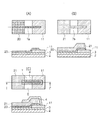
第2電極21を構成する金属箔は、図4(B)に示すように、予め所定形状で設けられた導電性粘着剤層20に同じ形状で貼り合わされる。金属箔は、予め所定形状に加工されて貼り合わされ、その加工手段としては、プレス加工等を例示できる。こうした金属箔で第2電極21を形成することにより、電極材料のコストを大幅に削減することができる。また、金属箔上にあらかじめ導電性粘着剤が設けられたテープ形状のものも使用できる。
As shown in FIG. 4B, the metal foil constituting the
金属箔20は、一般的な金属箔を入手して用いることができるので、フレキシブル基材2に対する熱負荷がなく、薄いフレキシブル基材2に「しわ」や「歪み」を生じさせない。また、従来のような樹脂バインダーを含む材料で銀電極を形成するのではなく、樹脂バインダーを含まない銀電極であるので、銀電極の抵抗率もより低くなるという利点がある。
Since the
第2電極21の平面視形状は、例えば図1に示すように、四角形等の角形であってもよいし、円形や楕円形であってもよいし、それらが組み合わされた形状であってもよい。また、図1に示すような一様なベタ状であってもよいし、例えば複数の窓部を有する第1電極(図示しない)としてもよいし、メッシュ部を有する第2電極(図示しない)としてもよい。このように、金属電極自体をベタ電極ではなく、窓部やメッシュ部を有するように形成することにより、その後に第2電極上に設けられる薬剤ジェル5の保持性を高めることができ、薬剤ジェル5の生体膜への透過をより促進させることができる。なお、窓部の大きさやメッシュ部の開口の大きさは、任意に設計することができる。
For example, as shown in FIG. 1, the
第2電極21は、図2に示すように、配線6を介して第1電極11に接続されている。第1電極11と第2電極21との間で起電力が生じるので、配線することにより、自己発電回路となり、自己発電型のイオントフォレシス装置31を構成できる。
As shown in FIG. 2, the
(接続配線)
接続配線7は、第1電極11と第2電極21との重なり部分であり、第1電極11と第2電極21とを接続させるための配線である。こうした接続配線7は、図4(C)に示すように、第1電極11と第2電極21の形成時に一括形成できる。その結果、製造のし易い構造形態を有する生体用電極を提供できる。
(Connection wiring)
The
接続配線7は、上記した第1電極11の形成工程及び上記した第2電極21の形成工程で、第1電極11及び第2電極21の一方又は両方から延びた接続配線7を重ねて形成される。一例としては、図4(A)(B)に示すように、導電性粘着剤層20から延びる接続配線7aと、その導電性粘着剤層20上に貼り合わされる金属箔(第2電極21)から延びる接続配線7bとが重なり、その重なった接続配線7が第1電極11に電気的に接触することにより、第1電極11と第2電極21とが接続される。
The
(絶縁膜)
絶縁膜4は、第1電極11及び第2電極21の一方又は両方から延びて重なる接続配線7を覆うように設けられる。絶縁膜4は、少なくとも接続配線7を覆うことが必要であり、接続配線7以外は覆う必要はないが、生体用電極1の機能に支障が生じない範囲で他の領域に設けてもよい。絶縁膜4の構成材料は、絶縁性を有するものであれば特に限定されないが、成膜とパターニングの容易さから、例えばスクリーン印刷ではエポキシアクリレート及びウレタンアクリレート等を主成分とした溶剤を含まない紫外線硬化材料、又はジエチレングリコールアセテート、エーテルグルコール等の溶剤を含んだ熱硬化材料等を挙げることができる。また、絶縁膜は、ポリエチレンテレフタレート等の絶縁性のフレキシブル基板を貼り合わせる形でもよい。
(Insulating film)
The insulating
絶縁膜4の形成方法は、一般的な絶縁樹脂等の形成方法を適用できる。例えば、絶縁性の樹脂系材料を各種の塗布方法で塗布して形成する。絶縁膜4の厚さは特に限定されないが、例えば、10μm以上200μm以下とすることができる。上述のように、ポリエチレンテレフタレート等の絶縁性のフレキシブル基板を貼り合わせる形でもよい。こうした絶縁膜4は、薬剤ジェル5を介して皮膚にフレキシブルに貼り合わせた場合であっても、両電極11,21の接続信頼性を維持することができ、信頼性が高く、接触抵抗も低い生体用電極1とすることができる。
As a method of forming the insulating
[イオントフォレシス装置]
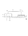
イオントフォレシス装置31は、本発明に係る生体用電極1を備えている。具体的には、図2に示すように、上記した生体用電極1を有し、その生体用電極1を構成する第1電極11及び第2電極21を覆うように薬剤ジェル5が設けられている。第1電極11及び第2電極21は配線6で接続され、両電極間で生じる起電力により、自己発電型のイオントフォレシス装置31となる。このイオントフォレシス装置31は、使い捨て型の生体用電極を構成する金属電極材料の使用量を必要最小限に抑えることができ、イオントフォレシス装置のコスト低減を図ることができる。
[Iontophoresis equipment]
The
薬剤ジェル5は、1種類又は2種類以上の薬剤を含むジェルである。こうした薬剤ジェル5を用いるので、効率よく、薬剤を体内へ浸透させることが可能となる。特に2種類以上用いることが好ましい。なお、薬剤ジェル5の使用形態としては、第1電極11及び第2電極21のいずれも覆うように1種類の薬剤ジェル5が設けられていてもよいし、第1電極11及び第2電極21のそれぞれを別に覆うように1種類の薬剤ジェル5が設けられていてもよいし、第1電極11及び第2電極21のそれぞれを別に覆うようにそれぞれ異なる薬剤ジェル5が設けられていてもよい。なお、第1電極11や第2電極21に設けられる薬剤ジェル5は、1種類の薬剤ジェル5からなる単一薬剤であってもよいし、2種以上の薬剤ジェルを含む複合薬剤であってもよい。
The
薬剤ジェル5に含まれる薬剤としては、所望の効果を生じさせるために生体器官に供給される治療上の任意の能動物質を用いることができる。具体的には、主要な治療分野における治療薬を含むものであって、特に限定するものではないが、抗生物質及び抗ウィルス薬のような抗感染薬;鎮痛剤及び鎮痛剤複合物;麻酔剤、食欲抑制剤;抗関節炎薬;抗喘息薬;抗痙攣薬;抗うつ薬;抗糖尿薬;下痢止め薬;抗ヒスタミン薬;抗炎症薬;抗偏頭痛製剤;アンチモーション病(antimotion sickness)製剤;抗嘔吐剤;抗腫瘍剤;抗パーキンソン剤;心臓刺激剤;止痒剤;抗精神病薬;解熱剤;胃腸用及び尿道用を含む抗痙攣薬;抗コリン作用薬;交感神経様作用薬;キサンチン誘導体;カルシウム遮断薬を含む循環器製剤;β(ベータ)遮断薬;β(ベータ)作動薬;抗不整脈薬;高血圧症薬;ACE抑制薬;利尿剤;一般血管、冠状動脈、末梢血管及び脳血管を含む血管拡張薬;中央神経興奮剤;咳及び風邪製剤;鬱血除去薬;診断薬;ホルモン;催眠剤;免疫抑制剤;筋弛緩剤;副交感神経病薬;副交感神経作用薬;プロスタグラジン;蛋白質;ペプチド;精神刺激薬;鎮静剤及び精神安定剤(トランキライザー)を含むものを挙げることができる。
As the drug contained in the
イオントフォレシス装置31は、本発明に係る生体用電極1を構成電極として好ましく用いられる他、低周波治療器の電極、心電図、筋電、脳波等の内臓機能検査用電極、電気メス等のアース電極等の生体に貼付して治療や検査を行う生体用電極として好適使用することができる。
The
生体用電極1を有したイオントフォレシス装置31は、生体用電極1を構成する金属電極材料の使用量を必要最小限に抑えることができ、装置全体のコスト低減を図ることができる。
The
1 生体用電極
2 フレキシブル基材
3 プライマー層
4 絶縁膜
5 薬剤ジェル
6 配線
7 接続配線
7a 導電性粘着剤層の接続配線
7b 第2電極の接続配線
8 リフトオフ用膜
11 第1電極
11’ 金属蒸着膜
20 導電性粘着剤層
21 第2電極(金属箔)
31 イオントフォレシス装置
DESCRIPTION OF
31 Iontophoresis device
Claims (8)
An iontox comprising the biomedical electrode according to any one of claims 1 to 4, and a drug gel provided so as to cover the first electrode and the second electrode constituting the biomedical electrode. Foresis device.
Priority Applications (1)
| Application Number | Priority Date | Filing Date | Title |
|---|---|---|---|
| JP2012020328A JP2013158366A (en) | 2012-02-01 | 2012-02-01 | Electrode for living body, method for manufacturing the same and iontophoretic apparatus |
Applications Claiming Priority (1)
| Application Number | Priority Date | Filing Date | Title |
|---|---|---|---|
| JP2012020328A JP2013158366A (en) | 2012-02-01 | 2012-02-01 | Electrode for living body, method for manufacturing the same and iontophoretic apparatus |
Publications (1)
| Publication Number | Publication Date |
|---|---|
| JP2013158366A true JP2013158366A (en) | 2013-08-19 |
Family
ID=49171130
Family Applications (1)
| Application Number | Title | Priority Date | Filing Date |
|---|---|---|---|
| JP2012020328A Pending JP2013158366A (en) | 2012-02-01 | 2012-02-01 | Electrode for living body, method for manufacturing the same and iontophoretic apparatus |
Country Status (1)
| Country | Link |
|---|---|
| JP (1) | JP2013158366A (en) |
Cited By (1)
| Publication number | Priority date | Publication date | Assignee | Title |
|---|---|---|---|---|
| JP2017104663A (en) * | 2013-07-12 | 2017-06-15 | 賢司 小蒲 | Biological battery treatment tool |
-
2012
- 2012-02-01 JP JP2012020328A patent/JP2013158366A/en active Pending
Cited By (1)
| Publication number | Priority date | Publication date | Assignee | Title |
|---|---|---|---|---|
| JP2017104663A (en) * | 2013-07-12 | 2017-06-15 | 賢司 小蒲 | Biological battery treatment tool |
Similar Documents
| Publication | Publication Date | Title |
|---|---|---|
| CN1114452C (en) | Multifunctional Biomedical Electrodes | |
| Leal et al. | Untethered disposable health monitoring electronic patches with an integrated Ag2O–Zn battery, a AgInGa current collector, and hydrogel electrodes | |
| JP4171422B2 (en) | Electrode structure | |
| JP2004510481A (en) | Floating electrode | |
| JPS62284629A (en) | Biomedical electrode and its production | |
| JPH04131209U (en) | biomedical electrodes | |
| US20250057457A1 (en) | Electrode device for living body | |
| CN110573070B (en) | Sheet for biosensor | |
| CN107405097A (en) | Organism electrode assembly | |
| JP2013158365A (en) | Electrode for living body, method for manufacturing the same and iontophoretic apparatus | |
| JP2014045823A (en) | Bioelectrode, method for manufacturing the same and iontophoresis device | |
| JP2013158366A (en) | Electrode for living body, method for manufacturing the same and iontophoretic apparatus | |
| JP3320306B2 (en) | Method for manufacturing multipolar bioelectrode | |
| US7860546B2 (en) | Medical electrode with self-lifting tabs | |
| JP2013158364A (en) | Method of manufacturing biomedical electrode and method of manufacturing biomedical electrode sheet | |
| JP2014054421A (en) | Biomedical electrode, method for manufacturing the same, iontophoresis apparatus | |
| JP2013158363A (en) | Biomedical electrode, sheet for the same, and iontophoretic apparatus | |
| CN108420427B (en) | Electrode material structure of wearable electrocardio sensor and processing method thereof | |
| JP4316250B2 (en) | Electrode structure | |
| US20050283219A1 (en) | Packaging for medical pads and electrodes | |
| JP7706604B1 (en) | Medical Devices | |
| JP2002345977A (en) | Ion introduction tool | |
| WO2026070508A1 (en) | Electrode device for living body | |
| CN111888642A (en) | A kind of skin patch for transdermal iontophoresis drug delivery | |
| JP2026058977A (en) | Biomedical electrode device |