JP2013151237A - Vehicle seat and method of sewing webbing - Google Patents
Vehicle seat and method of sewing webbing Download PDFInfo
- Publication number
- JP2013151237A JP2013151237A JP2012013368A JP2012013368A JP2013151237A JP 2013151237 A JP2013151237 A JP 2013151237A JP 2012013368 A JP2012013368 A JP 2012013368A JP 2012013368 A JP2012013368 A JP 2012013368A JP 2013151237 A JP2013151237 A JP 2013151237A
- Authority
- JP
- Japan
- Prior art keywords
- loop
- skin
- seat
- sides
- width direction
- Prior art date
- Legal status (The legal status is an assumption and is not a legal conclusion. Google has not performed a legal analysis and makes no representation as to the accuracy of the status listed.)
- Granted
Links
- 238000009958 sewing Methods 0.000 title claims abstract description 38
- 238000000034 method Methods 0.000 title claims description 18
- 238000005452 bending Methods 0.000 claims abstract description 11
- 210000003491 skin Anatomy 0.000 claims description 118
- 239000004744 fabric Substances 0.000 claims description 35
- 238000005520 cutting process Methods 0.000 claims description 10
- 210000002615 epidermis Anatomy 0.000 claims description 4
- 235000021170 buffet Nutrition 0.000 claims 1
- 241000447437 Gerreidae Species 0.000 description 3
- 230000000694 effects Effects 0.000 description 2
- 230000004048 modification Effects 0.000 description 2
- 238000012986 modification Methods 0.000 description 2
- 239000011347 resin Substances 0.000 description 2
- 229920005989 resin Polymers 0.000 description 2
- JOYRKODLDBILNP-UHFFFAOYSA-N Ethyl urethane Chemical compound CCOC(N)=O JOYRKODLDBILNP-UHFFFAOYSA-N 0.000 description 1
- 239000006260 foam Substances 0.000 description 1
- 239000000463 material Substances 0.000 description 1
Images


Classifications
-
- B—PERFORMING OPERATIONS; TRANSPORTING
- B60—VEHICLES IN GENERAL
- B60R—VEHICLES, VEHICLE FITTINGS, OR VEHICLE PARTS, NOT OTHERWISE PROVIDED FOR
- B60R21/00—Arrangements or fittings on vehicles for protecting or preventing injuries to occupants or pedestrians in case of accidents or other traffic risks
- B60R21/02—Occupant safety arrangements or fittings, e.g. crash pads
- B60R21/16—Inflatable occupant restraints or confinements designed to inflate upon impact or impending impact, e.g. air bags
- B60R21/20—Arrangements for storing inflatable members in their non-use or deflated condition; Arrangement or mounting of air bag modules or components
- B60R21/207—Arrangements for storing inflatable members in their non-use or deflated condition; Arrangement or mounting of air bag modules or components in vehicle seats
-
- D—TEXTILES; PAPER
- D05—SEWING; EMBROIDERING; TUFTING
- D05B—SEWING
- D05B23/00—Sewing apparatus or machines not otherwise provided for
-
- B—PERFORMING OPERATIONS; TRANSPORTING
- B60—VEHICLES IN GENERAL
- B60N—SEATS SPECIALLY ADAPTED FOR VEHICLES; VEHICLE PASSENGER ACCOMMODATION NOT OTHERWISE PROVIDED FOR
- B60N2/00—Seats specially adapted for vehicles; Arrangement or mounting of seats in vehicles
- B60N2/58—Seat coverings
- B60N2002/5808—Seat coverings comprising opening zones for airbags
-
- B—PERFORMING OPERATIONS; TRANSPORTING
- B60—VEHICLES IN GENERAL
- B60R—VEHICLES, VEHICLE FITTINGS, OR VEHICLE PARTS, NOT OTHERWISE PROVIDED FOR
- B60R21/00—Arrangements or fittings on vehicles for protecting or preventing injuries to occupants or pedestrians in case of accidents or other traffic risks
- B60R21/02—Occupant safety arrangements or fittings, e.g. crash pads
- B60R21/16—Inflatable occupant restraints or confinements designed to inflate upon impact or impending impact, e.g. air bags
- B60R21/20—Arrangements for storing inflatable members in their non-use or deflated condition; Arrangement or mounting of air bag modules or components
- B60R21/207—Arrangements for storing inflatable members in their non-use or deflated condition; Arrangement or mounting of air bag modules or components in vehicle seats
- B60R2021/2076—Removable covers with tear seams
Abstract
Description
本発明は、車両用シート、及び力布の縫製方法に関する。 The present invention relates to a vehicle seat and a sewing method for a buff.
エアバッグを有するサイドエアバッグ装置と、エアバッグの展開圧を受けて前面カバー部の端部と側面カバー部の端部との縫合部を開破させる2枚の力布を備えた車両用シートが知られている(例えば、特許文献1,2)。 A vehicle seat comprising a side airbag device having an airbag, and two baffles that receive a deployment pressure of the airbag and break a stitched portion between an end portion of a front cover portion and an end portion of a side cover portion Are known (for example, Patent Documents 1 and 2).
しかしながら、特許文献1,2に開示されたような車両用シートでは、2枚の力布の端部を前面カバー部の端部及び側面カバー部の端部にそれぞれ縫い合わせた後に、これらの前面カバー部の端部と側面カバー部の端部とを更に縫い合わせるか、若しくはこれと逆に、前面カバー部の端部と側面カバー部の端部とを縫い合わせた後に、これらの前面カバー部の端部及び側面カバー部の端部に2枚の力布の端部をそれぞれ縫い合わせる必要があるため、縫製作業に手間がかかる。
However, in the vehicle seats disclosed in
本発明は、上記の事実を考慮し、サイド表皮及びフロント表皮に対する力布の縫製作業の手間を低減することを目的とする。 The present invention has been made in consideration of the above-described facts, and an object of the present invention is to reduce the labor of sewing a power cloth on the side skin and the front skin.
請求項1に記載の車両用シートは、シートバックのサイド部をシート幅方向の外側から覆うサイド表皮と、前記サイド部をシート前後方向の前側から覆うと共に、前記サイド表皮と縫い合わされるフロント表皮と、前記サイド部の内部に設けられ、ガスの供給を受けて前記サイド表皮と前記フロント表皮との縫合部へ向けて展開するサイドエアバッグを有するサイドエアバッグモジュールと、長手方向の中間部がループ状に折り曲げられて形成されて前記縫合部をシート幅方向の両側から挟み込み、両側のループ端部が前記縫合部に縫い合わされると共に脆弱部が形成されたループ状部を有し、展開された前記サイドエアバッグに対して一端側がシート幅方向の外側に配置されると共に他端側がシート幅方向の内側に配置され、該サイドエアバッグから受けた展開圧を前記縫合部及び前記脆弱部に引張り力として伝達する力布と、を備えている。 The vehicle seat according to claim 1, wherein a side skin that covers a side portion of a seat back from the outside in the seat width direction, a front skin that covers the side portion from the front side in the seat front-rear direction and is sewn to the side skin. And a side airbag module having a side airbag that is provided inside the side portion and is deployed toward a stitched portion of the side skin and the front skin upon receiving gas supply, and a longitudinal intermediate portion. Formed by being bent in a loop shape, the stitched portion is sandwiched from both sides in the sheet width direction, loop ends on both sides are stitched to the stitched portion, and a loop-shaped portion having a fragile portion is formed and deployed. One end side of the side airbag is disposed outside in the seat width direction and the other end side is disposed inside in the seat width direction. The deployment pressure received from Tsu grayed and a, a webbing for transmitting a tensile force to the suture part and the fragile portion.
請求項1に係る車両用シートによれば、ガスの供給を受けてサイドエアバッグがサイド表皮とフロント表皮との縫合部へ向けて展開されると、力布の一端側及び他端側がサイドエアバッグから展開圧を受ける。この展開圧は、サイド表皮とフロント表皮との縫合部及び力布のループ状部に形成された脆弱部に引張り力として伝達される。この引張り力によって縫合部が開裂されると共に脆弱部が破断されると、展開されたサイドエアバッグがシートバックのサイド部のシート前後方向の前側へ放出される。 According to the vehicle seat of the first aspect, when the side airbag is deployed toward the stitched portion between the side skin and the front skin upon receiving the gas supply, one end side and the other end side of the buff are side air. Receive deployment pressure from the bag. This unfolding pressure is transmitted as a tensile force to the stitched portion between the side skin and the front skin and the fragile portion formed in the loop-like portion of the force cloth. When the stitching portion is cleaved by this pulling force and the fragile portion is broken, the deployed side airbag is released to the front side in the seat front-rear direction of the side portion of the seat back.
ここで、力布の長手方向の中間部をループ状に折り曲げて形成されたループ状部は、サイド表皮とフロント表皮との縫合部をシート幅方向の両側から挟み込んだ状態で、その両側のループ端部が縫合部に縫い合わされている。このように力布の長手方向の中間部に形成されたループ状部によって縫合部をシート幅方向の両側から挟み込むことにより、ループ状部の両側のループ端部と縫合部とを一緒に縫い合わせることができる。従って、2枚の力布の端部をサイド表皮及びフロント表皮に別々に縫い合わせた構成と比較して、縫製作業の手間が低減される。 Here, the loop-shaped part formed by bending the longitudinal part of the buff in the loop shape is the loop on both sides of the stitched part of the side epidermis and the front epidermis sandwiched from both sides in the seat width direction. The end is sewn to the stitched portion. In this way, by stitching the stitched portion from both sides in the seat width direction by the loop-shaped portion formed in the middle portion in the longitudinal direction of the bundling, the loop ends and the stitched portions on both sides of the loop-shaped portion are sewn together. Can do. Therefore, the labor of the sewing work is reduced as compared with the configuration in which the end portions of the two blankets are separately sewn to the side skin and the front skin.
請求項2に記載の車両用シートは、請求項1に記載の車両用シートにおいて、両側の前記ループ端部同士が、前記縫合部を挟んで縫い合わされている。 The vehicle seat according to a second aspect is the vehicle seat according to the first aspect, wherein the loop end portions on both sides are sewn together with the stitched portion interposed therebetween.
請求項2に係る車両用シートによれば、サイド表皮とフロント表皮との縫合部を挟んでループ状部の両側のループ端部同士を縫い合わせることにより、2枚の力布の端部をサイド表皮及びフロント表皮に別々に縫い合わせた構成と比較して、縫製作業の手間が低減される。
According to the vehicle seat according to
請求項3に記載の車両用シートは、請求項1又は請求項2に記載の車両用シートにおいて、前記脆弱部が、前記ループ状部に形成された貫通孔及び切れ込みの少なくとも一方である。 The vehicle seat according to claim 3 is the vehicle seat according to claim 1 or 2, wherein the weakened portion is at least one of a through hole and a cut formed in the loop-shaped portion.
請求項3に係る車両用シートによれば、ループ状部には、脆弱部としての貫通孔及び切れ込みの少なくとも一方が形成されている。これにより、力布がサイドエアバッグから受けた展開圧がループ状部に伝達され、当該ループ状部が貫通孔及び切れ込みの少なくとも一方を起点として破断すると、ループ状部の破断部及び開破されたサイド表皮とフロント表皮との縫合部から、展開されたサイドエアバッグがシートバックのサイド部のシート前後方向の前側へ放出される。 According to the vehicle seat of the third aspect, at least one of the through hole and the cut as the fragile portion is formed in the loop-shaped portion. As a result, the deployment pressure received by the baffle from the side airbag is transmitted to the loop-shaped portion, and when the loop-shaped portion breaks starting from at least one of the through hole and the notch, the broken portion of the loop-shaped portion and the broken portion are broken. The deployed side airbag is released from the stitched portion of the side skin and the front skin to the front side in the seat front-rear direction of the side portion of the seat back.
請求項4に記載の力布の縫製方法は、脆弱部が形成された力布の長手方向の中間部をループ状に折り曲げて形成されたループ状部によってサイド表皮の端部及びフロント表皮の端部を両側から挟み込み、前記ループ状部の両側のループ端部、前記サイド表皮の端部、及び前記フロント表皮の端部を縫い合わせる。 5. The method for sewing a power cloth according to claim 4, wherein the end portion of the side skin and the end of the front skin are formed by a loop-shaped portion formed by bending an intermediate portion in the longitudinal direction of the power fabric in which the fragile portion is formed into a loop shape. The portion is sandwiched from both sides, and the loop end portions on both sides of the loop-shaped portion, the end portions of the side skin, and the end portions of the front skin are sewn together.
請求項4に係る力布の縫製方法によれば、脆弱部が形成された力布の長手方向の中間部をループ状に折り曲げて形成されたループ状部によって、サイド表皮の端部及びフロント表皮の端部を両側から挟み込むことにより、ループ状部の両側のループ端部、サイド表皮の端部、及びフロント表皮の端部を一緒に縫い合わせることができる。従って、2枚の力布の端部をサイド表皮及びフロント表皮に別々に縫い合わせた構成と比較して、縫製作業の手間が低減される。 According to the sewing method of the power cloth according to claim 4, the end portion of the side skin and the front skin are formed by the loop-shaped portion formed by bending the longitudinal intermediate portion of the power fabric in which the fragile portion is formed into a loop shape. By sandwiching the end portions of the loop-shaped portion from both sides, the loop end portions on both sides of the loop-shaped portion, the end portions of the side skin, and the end portions of the front skin can be sewn together. Therefore, the labor of the sewing work is reduced as compared with the configuration in which the end portions of the two blankets are separately sewn to the side skin and the front skin.
請求項5に記載の力布の縫製方法は、力布の長手方向の中間部をループ状に折り曲げて形成されたループ状部によってサイド表皮の端部及びフロント表皮の端部を両側から挟み込み、前記ループ状部の両側のループ端部、前記サイド表皮の端部、及び前記フロント表皮の端部を縫い合わせる縫製工程と、前記ループ状部を切断する切断工程と、を備えている。 The sewing method of the power fabric according to claim 5, wherein the end portion of the side skin and the end portion of the front skin are sandwiched from both sides by a loop-shaped portion formed by bending the longitudinal intermediate portion of the power fabric into a loop shape, A sewing step for sewing the loop end portions on both sides of the loop-shaped portion, the end portions of the side skin, and the end portions of the front skin; and a cutting step for cutting the loop-shaped portion.
請求項5に係る力布の縫製方法によれば、先ず、縫製工程において、力布の長手方向の中間部をループ状に折り曲げて形成されたループ状部によってサイド表皮の端部及びフロント表皮を両側から挟み込み、これらのループ状部の両側のループ端部、サイド表皮の端部、及びフロント表皮の端部を縫い合わせる。次に、切断工程において、ループ状部を切断する。 According to the sewing method of the power cloth according to claim 5, first, in the sewing process, the end portion of the side skin and the front skin are formed by the loop-shaped portion formed by bending the intermediate portion in the longitudinal direction of the power fabric in a loop shape. The loop ends on both sides of these loop-shaped portions, the end portions of the side skin, and the end portions of the front skin are sewn together from both sides. Next, in the cutting step, the loop-shaped part is cut.
このように縫製工程において力布のループ状部によってサイド表皮の端部及びフロント表皮の端部を両側から挟み込むことにより、ループ状部の両側のループ端部、サイド表皮の端部、及びフロント表皮の端部を一緒に縫い合わせることができる。従って、2枚の力布の端部をサイド表皮及びフロント表皮に別々に縫い合わせた構成と比較して、縫製作業の手間が低減される。 In this way, by sandwiching the end portion of the side skin and the end portion of the front skin from both sides by the loop-like portion of the bundling in the sewing process, the loop end portion on both sides of the loop-like portion, the end portion of the side skin, and the front skin Can be sewn together. Therefore, the labor of the sewing work is reduced as compared with the configuration in which the end portions of the two blankets are separately sewn to the side skin and the front skin.
また、切断工程において力布のループ状部を切断することにより、ループ状部の切断部及び開破されたサイド表皮の端部とフロント表皮の端部との縫合部から、展開されたサイドエアバッグがシートバックのサイド部のシート前後方向の前側へ放出される。 Further, by cutting the loop-shaped portion of the bundling in the cutting step, the side air developed from the cut portion of the loop-shaped portion and the stitched portion of the end portion of the opened side skin and the end portion of the front skin is obtained. The bag is discharged to the front side in the seat front-rear direction of the side portion of the seat back.
以上説明したように、本発明に係る車両用シート及び力布の縫製方法によれば、サイド表皮及びフロント表皮に対する力布の縫製作業の手間を低減することができる。 As described above, according to the vehicular seat and the baffle sewing method according to the present invention, it is possible to reduce the labor of the bundling work for the side skin and the front skin.
以下、図面を参照しながら、本発明の一実施形態に係る車両用シート及び力布の縫製方法について説明する。なお、各図において適宜示される矢印Xはシート前後方向の前側を示し、矢印Yはシート幅方向の外側を示し、矢印Zはシート上下方向の上側を示している。 Hereinafter, a method for sewing a vehicular seat and a force cloth according to an embodiment of the present invention will be described with reference to the drawings. Note that an arrow X appropriately shown in each drawing indicates a front side in the front-rear direction of the seat, an arrow Y indicates an outer side in the seat width direction, and an arrow Z indicates an upper side in the seat vertical direction.
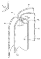
図1には、本実施形態に係る車両用シート10が示されている。車両用シート10は、例えば運転席を構成するものであり、乗員が着座するシートクッション12と、シートクッション12のシート前後方向の後端部に傾倒可能に支持され、乗員の背部を支持するシートバック14と、シートバック14のシート上下方向の上端部に設けられ、乗員の頭部を支持するヘッドレスト16とを備えている。
FIG. 1 shows a
シートバック14は、シート幅方向の中央部を構成するシートバック本体部14Aと、シートバック本体部14Aのシート幅方向の外側の端部に一体的に設けられた外側サイド部14Bと、シートバック本体部14Aのシート幅方向の内側の端部に一体的に設けられた内側サイド部14Cとを備えている。なお、外側サイド部14Bのシート幅方向の外側には、図示しない車両用サイドドアが配置されている。
The
図2に示されるように、サイド部としての外側サイド部14Bの内部には、当該外側サイド部14Bに沿ってシート上下方向に延びるシートバックサイドフレーム18が設けられている。シートバックサイドフレーム18は、シート幅方向の内側が開口された断面略C形状に形成されており、シート前後方向に沿った外側壁部18Aと、外側壁部18Aのシート前後方向の前端部からシート幅方向の内側へ屈曲された前側壁部18Bと、外側壁部18Aのシート前後方向の後端部からシート幅方向の内側へ屈曲された後側壁部18Cとを有している。
As shown in FIG. 2, a seat
なお、図示を省略するが、シートバック14の内側サイド部14C(図1参照)には、シートバックサイドフレーム18と対をなすシートバックサイドフレームが設けられている。これら一対のシートバックサイドフレーム18、及び一対のシートバックサイドフレーム18の上端部をシート幅方向に連結するシートアッパフレーム等によってシートバックフレームが構成されている。
Although not shown, a seat back side frame that forms a pair with the seat back
シートバックサイドフレーム18の外側壁部18Aには、後述するサイドエアバッグ装置50のサイドエアバッグモジュール(以下、単に「エアバッグモジュール」ともいう)52が組み付けられている。シートバックサイドフレーム18の周囲には、ウレタンフォーム等で形成されたシートバックパッド22が配置されている。シートバックパッド22は、パッドサイド部24とパッドフロント部28とを有している。
A side airbag module (hereinafter, also simply referred to as “airbag module”) 52 of a
パッドサイド部24は断面略L字形状に形成されており、シートバックサイドフレーム18のシート幅方向の外側に配置されている。このパッドサイド部24とシートバックサイドフレーム18との間にエアバッグモジュール52が収納されるエアバッグモジュール収納部32が形成されている。パッドサイド部24のシート前後方向の後端部24Rは、エアバッグモジュール52のシート幅方向の外側からシート前後方向の後側へ回り込み、シートバックサイドフレーム18の後側壁部18Cに達している。また、パッドサイド部24の後端部24Rには、シートバック14の背面を構成するバックカバートリム26の端部26Aがシート前後方向の後側から重ねられている。一方、パッドサイド部24のシート前後方向の前端部24Fは、エアバッグモジュール52よりもシート前後方向の前側に配置されている。
The
シートバックパッド22のパッドフロント部28は、シートバックサイドフレーム18のシート前後方向の前側に配置されている。パッドフロント部28は、外側サイド部14Bと内側サイド部14C(図1参照)とにわたって配置されており、そのシート幅方向の外側の外側端部28Tがエアバッグモジュール52のシート前後方向の前側でパッドサイド部24の前端部24Fと対向している。これらのパッドフロント部28の外側端部28Tとパッドサイド部24の前端部24Fとの間には、後述するサイドエアバッグ54が展開されたときに、当該サイドエアバッグ54を外部へ放出させる放出路30が形成されている。
The
また、パッドサイド部24の外面24A及びパッドフロント部28の外面28Aは、サイド表皮40及びフロント表皮42によってそれぞれ被覆されている。サイド表皮40はパッドサイド部24のシート幅方向の外側に配置されており、そのシート前後方向の前端部40Fがパッドサイド部24の前端部24Fに沿って放出路30内へ挿入されている。フロント表皮42は、パッドフロント部28のシート前後方向の前側に配置されており、そのシート幅方向の外側の外側端部42Tがパッドフロント部28の外側端部28Tに沿って放出路30内へ挿入されている。これらのサイド表皮40の前端部40Fとフロント表皮42の外側端部42Tとは、放出路30の出口付近において、後述する力布70のループ状部70Lのループ端部70L1,70L2と共に共縫いされている。以下、サイド表皮40の前端部40Fとフロント表皮42の外側端部42Tとが縫い合わされる部位を縫合部44という。
Further, the
サイドエアバッグ装置50は、エアバッグモジュール52と、一枚の力布70とを備えている。エアバッグモジュール52は、収容ケース56と、収容ケース56に折り畳まれた状態で収容されたサイドエアバッグ54と、収容ケース56に収容され、サイドエアバッグ54にガスを供給するガス供給手段としての図示しないインフレータとを有し、エアバッグモジュール収納部32に収納されている。サイドエアバッグ54は、布や樹脂シート等により袋状に形成されており、インフレータからガスの供給を受けて膨張しながら展開するようになっている。なお、図2には、展開されたサイドエアバッグ54の外形が二点鎖線で示されている。
The
収容ケース56のシート幅方向の内側の内側面56Aには、連結部材としてのスタッドボルト58が設けられている。このスタッドボルト58は、収容ケース56の内側面56Aからシートバックサイドフレーム18の外側壁部18Aへ向けて突出している。一方、シートバックサイドフレーム18の外側壁部18Aには貫通孔20が形成されている。この貫通孔20に貫通されたスタッドボルト58及びナット60によって、エアバッグモジュール52がシートバックサイドフレーム18の外側壁部18Aに連結されている。
A
なお、収容ケース56の内側面56Aには、少なくとも2つのスタッドボルト58がシート上下方向に間隔を空けて設けられている。また、シートバックサイドフレーム18の外側壁部18Aには、前述した少なくとも2つのスタッドボルト58がそれぞれ貫通される少なくとも2つの貫通孔20がシート上下方向に間隔を空けて形成されている。
Note that at least two
力布70は、サイド表皮40及びフロント表皮42よりも伸び難い布や樹脂シート等によって帯状に形成されている。なお、本実施形態では、力布70は、サイドエアバッグ54と同程度の強度を有する材料で形成されている。
The
力布70は、その長手方向の両端部が縫い合わされており、シート上下方向の両側が開口されたリング状(筒状)に形成されている。この力布70の内側にエアバッグモジュール52が配置されている。また、力布70の長手方向の中間部には、後述するループ状部70Lが形成されている。ループ状部70Lの各ループ端部70L1,70L2は、サイド表皮40の前端部40F及びフロント表皮42の外側端部42Tに共縫いされている。以下、力布70におけるループ状部70Lよりも一端側の部位を外側シート部70Aとし、力布70におけるループ状部70Lよりも他端側の部位を内側シート部70Bとして説明する。
The
力布70の外側シート部70Aは、ループ状部70Lのシート幅方向の外側のループ端部70L1から放出路30及びパッドサイド部24とエアバッグモジュール52との間を通ってシート前後方向の後側へ延びると共に、エアバッグモジュール52の後端部に沿ってシート幅方向の内側へ折り返されている。つまり、力布70の外側シート部70Aは、展開されたサイドエアバッグ54に対してシート幅方向の外側に配置されるようになっている。
The
また、外側シート部70Aの端部70A1(力布70の一端部)は、エアバッグモジュール52の収容ケース56の内側面56Aとシートバックサイドフレーム18の外側壁部18Aとの間へ周り込んでいる。この外側シート部70Aにおける端部70A1側の部位には、当該外側シート部70Aを厚さ方向に貫通する貫通孔72が形成されている。この貫通孔72には、前述したエアバッグモジュール52のスタッドボルト58が貫通されている。これにより、力布70の外側シート部70Aが、スタッドボルト58を介してシートバックサイドフレーム18に連結されている。つまり、力布70の外側シート部70Aは、スタッドボルト58によってシートバックサイドフレーム18の外側壁部18Aに共締めされている。
Further, the end portion 70A1 of the
なお、外側シート部70Aの端部70A1には、前述した少なくとも2つのスタッドボルト58がそれぞれ貫通される少なくとも2つの貫通孔72がシート上下方向に間隔を形成されている。
In the end portion 70A1 of the
一方、力布70の内側シート部70Bは、ループ状部70Lのシート幅方向の内側のループ端部70L2から放出路30を通ってエアバッグモジュール52とシートバックサイドフレーム18との間へ延出されている。つまり、力布70の内側シート部70Bは、展開されたサイドエアバッグ54に対してシート幅方向の内側に配置されるようになっている。
On the other hand, the
この内側シート部70Bの端部70B1(力布70の他端部)は、エアバッグモジュール52のスタッドボルト58のシート前後方向の前側で、縫い糸74によって力布70の外側シート部70Aの端部70A1と縫い合わされている。
An end portion 70B1 (the other end portion of the bundling 70) of the
なお、内側シート部70Bにエアバッグモジュール52のスタッドボルト58が貫通される貫通孔を形成し、スタッドボルト58によって内側シート部70Bをシートバックサイドフレーム18の外側壁部18Aに共締めすることも可能である。
A through-hole through which the
ここで、力布70のループ状部70Lの構成について詳説する。
Here, the configuration of the loop-shaped
図3に示されるように、ループ状部70Lは、力布70の長手方向の中間部を当該力布70の幅方向(シート上下方向)に沿ってループ状に折り曲げて形成されている。このループ状部70Lの内側にはサイド表皮40の前端部40Fとフロント表皮42の外側端部42Tとが重ね合わされた状態で挿入されており、ループ状部70Lにおける両側のループ端部70L1,70L2によってフロント表皮42の外側端部42T及びサイド表皮40の前端部40Fがシート幅方向の両側から挟み込まれている。これらのループ状部70Lのループ端部70L1,70L2同士は、フロント表皮42の外側端部42T及びサイド表皮40の前端部40Fを挟み込んだ状態で、縫い糸76により縫い合わされている。即ち、ループ状部70Lのループ端部70L1,70L2、フロント表皮42の外側端部42T、及びサイド表皮40の前端部40Fは共縫いされており、互いに縫い合わされている。
As shown in FIG. 3, the loop-shaped
なお、ループ状部70Lのループ端部70L1,70L2、フロント表皮42の外側端部42T、及びサイド表皮40の前端部40Fは、従来周知の種々の縫製方法によって縫い合わせることができる。また、ここでいうループ状部70Lのループ端部70L1,70L2とは、フロント表皮42の外側端部42T及びサイド表皮40の前端部40Fに縫い合わされたループ状部70Lの部位を意味する。更に、ここでいう力布70の長手方向とは、当該力布70をシートバック14に取り付けた状態において、力布70のシート上下方向に沿った幅方向と直交する方向を意味し、必ずしも力布70の長辺に沿った方向を意味するものでない。
The loop end portions 70L1 and 70L2 of the loop-shaped
また、図4に示されるように、ループ状部70Lの長手方向の中央部には、脆弱部としての複数の貫通孔80が形成されている。なお、図4では、縫い糸76の図示が省略されている。複数の貫通孔80は、ループ状部70Lを厚さ方向に貫通すると共にループ状部70Lの幅方向に間隔を空けて形成されている。また、本実施形態では、複数の貫通孔80が、縫合部44のシート前後方向の後側に配置されている。更に、複数の貫通孔80は、ループ状部70Lの幅方向(シート上下方向)に沿って直線上に配列されている。換言すると、複数の貫通孔80は、ループ状部70Lの幅方向に沿ってミシン目状に形成されている。これらの貫通孔80により、力布70の他の部位(外側シート部70A及び内側シート部70B)と比較して、ループ状部70Lが長手方向の引張り力Qに対して破断し易くなっている。
In addition, as shown in FIG. 4, a plurality of through-
次に、シートバックサイドフレームに対するサイドエアバッグ装置の組み付け方法の一例について説明する。 Next, an example of a method for assembling the side airbag device to the seat back side frame will be described.
はじめに、サイド表皮40及びフロント表皮42に対する力布70のループ状部70Lの縫製方法について説明する。先ず、図3に示されるように、サイド表皮40の前端部40Fの外面とフロント表皮42の外側端部42Tの外面とを重ね合わせる。この際、サイド表皮40の前端部40Fとフロント表皮42の外側端部42Tとを仮縫い等によって仮留めしても良い。この状態で、複数の貫通孔80が形成された力布70の長手方向の中間部を当該力布70の幅方向(シート上下方向)に沿ってループ状に折り曲げてループ状部70Lを形成する。
First, a method for sewing the loop-shaped
次に、ループ状部70Lの一方のループ端部70L1をサイド表皮40の前端部40Fの内面に重ね合わせると共にループ状部70Lの他方のループ端部70L2をフロント表皮42の外側端部42Tの内面に重ね合わせ、これらのループ端部70L1,70L2によってサイド表皮40の前端部40F及びフロント表皮42の外側端部42Tを両側から挟み込む。この状態で、ループ状部70Lのループ端部70L1,70L2、サイド表皮40の前端部40F、及びフロント表皮42の外側端部42Tを縫い糸76によって共縫いする。これにより、ループ状部70Lのループ端部70L1,70L2が、サイド表皮40の前端部40F及びフロント表皮42の外側端部42Tを挟んで縫い合わされる。
Next, one loop end portion 70L1 of the loop-shaped
次に、力布70の外側シート部70Aの端部70A1と内側シート部70Bの端部70B1を縫い糸74(図2参照)によって縫い合わせる。これにより、力布70がリング状に形成される。このように縫い合わされた力布70の外側シート部70A及び内側シート部70Bは、図2に示されるように、パッドサイド部24の前端部24Fとパッドフロント部28の外側端部28Tとの間に形成された放出路30を通してエアバッグモジュール収納部32内に配置され、その内側にエアバッグモジュール52が配置される。
Next, the end portion 70A1 of the
具体的には、シートバックサイドフレーム18に対してパッドサイド部24の後端部24Rをシート幅方向の外側へ移動させ、これらのパッドサイド部24の後端部24Rとシートバックサイドフレーム18との隙間からエアバッグモジュール収納部32内へエアバッグモジュール52を配置し、当該エアバッグモジュール52を力布70の内側に挿入する。この際、力布70の内側から外側シート部70Aに形成された貫通孔72にエアバッグモジュール52のスタッドボルト58を貫通させる。
Specifically, the
次に、エアバッグモジュール52をシートバックサイドフレーム18側へ移動させながら、当該エアバッグモジュール52のスタッドボルト58をシートバックサイドフレーム18の外側壁部18Aに形成された貫通孔20を貫通させる。そして、シートバックサイドフレーム18のシート幅方向の内側からスタッドボルト58にナット60を締め込み、エアバッグモジュール52とシートバックサイドフレーム18とを連結する。これにより、力布70の外側シート部70Aがシートバックサイドフレーム18の外側壁部18Aに共締めされ、力布70がシートバックサイドフレーム18の外側壁部18Aに連結(固定)される。その後、パッドサイド部24の後端部24Rをシートバックサイドフレーム18側へ移動させる。
Next, while moving the
次に、本実施形態に係る車両用シートの作用について説明する。 Next, the effect | action of the vehicle seat which concerns on this embodiment is demonstrated.
本実施形態に係る車両用シート10によれば、車両衝突時等にエアバッグモジュール52のインフレータ(図示省略)が作動すると、サイドエアバッグ54の内部にガスが供給され、サイドエアバッグ54がエアバッグモジュール52の前端部から放出路30へ向けて膨張しながら展開する。
According to the
サイドエアバッグ54が展開されると、力布70の外側シート部70A及び内側シート部70Bがサイドエアバッグ54の展開圧(膨張圧)を受けて伸張する。これにより、外側シート部70A及び内側シート部70Bがサイドエアバッグ54から受けた展開圧が、ループ状部70Lのループ端部70L1,70L2を介してサイド表皮40の前端部40Fとフロント表皮42の外側端部42Tとの縫合部44に当該縫合部44を開破させる引張り力P(図3参照)として伝達される。
When the
この引張り力Pによって縫い糸76が切られて縫合部44が開裂されると、ループ状部70Lのループ端部70L1,70L2がシート幅方向に離間し、ループ状部70Lが展開される。この結果、力布70の外側シート部70A及び内側シート部70Bがサイドエアバッグ54から受けた展開圧がループ状部70Lにおける貫通孔80の周辺部に当該ループ状部70Lを破断させる引張り力Q(図4参照)として伝達される。この引張り力Qによって、ループ状部70Lが貫通孔80を起点として破断すると、ループ状部70Lの破断部及び開破された縫合部44から、図2に二点鎖線で示されるように展開されたサイドエアバッグ54が外側サイド部14Bのシート前後方向の前側へ放出される。つまり、サイドエアバッグ54が車両用シート10に着座した乗員と図示しない車両用サイドドアとの間へ放出される。
When the
ここで、ループ状部70Lは、前述したようにサイド表皮40の前端部40Fとフロント表皮42の外側端部42Tとの縫合部44をシート幅方向の両側から挟み込んだ状態で、その両側のループ端部70L1,70L2同士が縫い合わされている。従って、2枚の力布の端部をサイド表皮40の前端部40F及びフロント表皮42の外側端部42Tに別々に縫い合わせた構成と比較して、縫合部44に対する力布70の縫製作業の手間が低減される。
Here, as described above, the loop-shaped
また、ループ状部70Lには、複数の貫通孔80が力布70の幅方向に間隔を空けて形成されている。これらの貫通孔80の間隔や各貫通孔80の形状、大きさを適宜変更することにより、ループ状部70Lに所定値以上の引張り力Qが作用したときに、当該ループ状部を破断させることができる。
In addition, a plurality of through
次に、上記実施形態に係る車両用シート及び力布の縫製方法の変形例について説明する。 Next, a modified example of the method for sewing the vehicle seat and the bundling according to the embodiment will be described.
上記実施形態では、ループ状部70Lに脆弱部としての複数の貫通孔80を形成したがこれに限らない。例えば、図5に示されるように、ループ状部70Lに下端側から上端側にわたる長孔状の1つの貫通孔82を形成しても良い。
In the said embodiment, although the some through-
また、脆弱部は貫通孔に限らず、例えば、ループ状部70Lの幅方向の端部に切れ込み(スリット)を形成しても良い。更に、これらの貫通孔及び切れ込みを適宜組み合わせてループ状部70Lを形成しても良い。つまり、ループ状部70Lには、脆弱部として、貫通孔及び切れ込みの少なくとも一方を形成することができる。
Further, the fragile portion is not limited to the through hole, and for example, a cut (slit) may be formed at the end portion in the width direction of the loop-shaped
更に、上記実施形態では、ループ状部70Lの長手方向の中央部に脆弱部としての貫通孔80を形成したがこれに限らない。脆弱部としての貫通孔80及び切り込みは、ループ状部70Lにおけるループ端部70L1,70L2間に形成されていれば良く、その配置は適宜変更可能である。
Furthermore, in the said embodiment, although the through-
また、上記実施形態では、脆弱部としての複数の貫通孔80が形成されたループ状部70Lをサイド表皮40の前端部40Fとフロント表皮42の外側端部42Tとの縫合部44に縫い合わせたが、ループ状部70Lを縫合部44に縫い合わせた後に、ループ状部70Lを切断することも可能である。
In the above embodiment, the loop-shaped
具体的には、例えば、縫製工程において、脆弱部としての貫通孔80等が形成されていない力布70の長手方向の中間部をループ状に折り曲げて形成されたループ状部によって、サイド表皮40の前端部40F及びフロント表皮42の外側端部42Tを両側から挟み込み、当該ループ状部の両側のループ端部、サイド表皮40の前端部40F、フロント表皮42の外側端部42Tを縫い合わせる。次に、切断工程において、ループ状部におけるループ端部間の所定の部位を切断し、当該ループ状部を分断する。
Specifically, for example, in the sewing process, the
このように縫製工程において、ループ状部の両側のループ端部、サイド表皮40の前端部40F、及びフロント表皮42の外側端部42Tを共縫いすることにより、上記実施形態と同様に、2枚の力布の端部をサイド表皮40の前端部40F及びフロント表皮42の外側端部42Tに別々に縫い合わせた構成と比較して、縫合部44に対する力布70の縫製作業の手間が低減される。
In this manner, in the sewing process, two ends of the loop-shaped portion, the
更に、切断工程においてループ状部を切断することにより、ループ状部の切断部及び開破されたサイド表皮40の前端部40Fとフロント表皮42の外側端部42Tとの縫合部44から、展開されたサイドエアバッグ54がシートバック14の外側サイド部14Bのシート前後方向の前側へ放出される。従って、上記実施形態と同様の作用及び効果を得ることができる。
Further, by cutting the loop-shaped portion in the cutting process, the loop-shaped portion and the
また、上記実施形態では、力布70の外側シート部70Aの端部70A1と内側シート部70Bの端部70B1とを縫い合わせたがこれに限らない。力布70の外側シート部70Aは、展開されたサイドエアバッグ54に対してシート幅方向の外側に配置され、当該サイドエアバッグ54から受けた展開圧を縫合部44及びループ状部70Lに伝達可能なように、その端部70A1側がサイドエアバッグモジュール52やシートバックサイドフレーム18を含むシートバックフレーム等に固定されていれば良い。これと同様に、力布70の内側シート部70Bは、展開されたサイドエアバッグ54に対してシート幅方向の内側に配置され、当該サイドエアバッグ54から受けた展開圧を引張り力として縫合部44及びループ状部70Lに伝達可能なように、その端部70B1側がサイドエアバッグモジュール52やシートバックサイドフレーム18を含むシートバックフレーム等に固定されていれば良い。
In the above embodiment, the end portion 70A1 of the
以上、本発明の一実施形態について説明したが、本発明はこうした実施形態に限定されるものでなく、一実施形態及び各種の変形例を適宜組み合わせて用いても良いし、本発明の要旨を逸脱しない範囲において、種々なる態様で実施し得ることは勿論である。 As mentioned above, although one embodiment of the present invention was described, the present invention is not limited to such an embodiment, and one embodiment and various modifications may be used in combination as appropriate, and the gist of the present invention will be described. Of course, various embodiments can be implemented without departing from the scope.
10 車両用シート
14 シートバック
14B 外側サイド部(サイド部)
40 サイド表皮
40F 前端部(サイド表皮の端部)
42 フロント表皮
42T 外側端部(フロント表皮の端部)
44 縫合部
52 サイドエアバッグモジュール
54 サイドエアバッグ
70 力布
70L ループ状部
70L1 ループ端部
70L2 ループ端部
70A 外側シート部(力布の一端側)
70B 内側シート部(力布の他端側)
80 貫通孔(脆弱部)
82 貫通孔(脆弱部)
DESCRIPTION OF
40
42
44
70B Inner sheet part (the other end of the buff)
80 Through hole (fragile part)
82 Through hole (fragile part)
Claims (5)
前記サイド部をシート前後方向の前側から覆うと共に、前記サイド表皮と縫い合わされるフロント表皮と、
前記サイド部の内部に設けられ、ガスの供給を受けて前記サイド表皮と前記フロント表皮との縫合部へ向けて展開するサイドエアバッグを有するサイドエアバッグモジュールと、
長手方向の中間部がループ状に折り曲げられて形成されて前記縫合部をシート幅方向の両側から挟み込み、両側のループ端部が前記縫合部に縫い合わされると共に脆弱部が形成されたループ状部を有し、展開された前記サイドエアバッグに対して一端側がシート幅方向の外側に配置されると共に他端側がシート幅方向の内側に配置され、該サイドエアバッグから受けた展開圧を前記縫合部及び前記脆弱部に引張り力として伝達する力布と、
を備えた車両用シート。 A side skin covering the side part of the seat back from the outside in the seat width direction;
A front skin that covers the side part from the front side in the front-rear direction of the seat and is sewn with the side skin,
A side airbag module having a side airbag that is provided inside the side portion and is deployed toward a stitched portion between the side epidermis and the front epidermis upon supply of gas;
A loop-shaped portion formed by bending the middle portion in the longitudinal direction into a loop shape, sandwiching the stitched portion from both sides in the sheet width direction, and stitching the loop end portions on both sides to the stitched portion and forming a fragile portion One end side of the deployed side airbag is disposed outside in the seat width direction and the other end side is disposed in the seat width direction, and the deployment pressure received from the side airbag is sewn. A webbing that transmits to the part and the fragile part as a tensile force;
Vehicle seat equipped with
請求項1に記載の車両用シート。 The loop ends on both sides are stitched together with the stitched portion interposed therebetween,
The vehicle seat according to claim 1.
請求項1又は請求項2に記載の車両用シート。 The fragile portion is at least one of a through-hole and a cut formed in the loop-shaped portion,
The vehicle seat according to claim 1 or 2.
力布の縫製方法。 The end portion of the side skin and the end portion of the front skin are sandwiched from both sides by the loop-like portion formed by bending the longitudinal middle portion of the buffet where the fragile portion is formed into a loop shape, on both sides of the loop-like portion. Loop end, end of the side skin, and end of the front skin,
Sewing method of force cloth.
前記ループ状部を切断する切断工程と、
を備えた力布の縫製方法。 The end portion of the side skin and the end portion of the front skin are sandwiched from both sides by a loop-like portion formed by bending the longitudinal middle portion of the bundling into a loop shape, and the loop end portions on both sides of the loop-like portion, the side A sewing step of sewing the end of the skin and the end of the front skin;
A cutting step of cutting the loop-shaped portion;
A method for sewing a rag.
Priority Applications (3)
| Application Number | Priority Date | Filing Date | Title |
|---|---|---|---|
| JP2012013368A JP5690289B2 (en) | 2012-01-25 | 2012-01-25 | Vehicle seat and sewing method |
| US13/746,666 US8807591B2 (en) | 2012-01-25 | 2013-01-22 | Vehicle seat and webbing sewing method |
| CN201310023464.XA CN103223917B (en) | 2012-01-25 | 2013-01-22 | Seat and sideband sewing method |
Applications Claiming Priority (1)
| Application Number | Priority Date | Filing Date | Title |
|---|---|---|---|
| JP2012013368A JP5690289B2 (en) | 2012-01-25 | 2012-01-25 | Vehicle seat and sewing method |
Publications (2)
| Publication Number | Publication Date |
|---|---|
| JP2013151237A true JP2013151237A (en) | 2013-08-08 |
| JP5690289B2 JP5690289B2 (en) | 2015-03-25 |
Family
ID=48796614
Family Applications (1)
| Application Number | Title | Priority Date | Filing Date |
|---|---|---|---|
| JP2012013368A Active JP5690289B2 (en) | 2012-01-25 | 2012-01-25 | Vehicle seat and sewing method |
Country Status (3)
| Country | Link |
|---|---|
| US (1) | US8807591B2 (en) |
| JP (1) | JP5690289B2 (en) |
| CN (1) | CN103223917B (en) |
Cited By (3)
| Publication number | Priority date | Publication date | Assignee | Title |
|---|---|---|---|---|
| JP2015147431A (en) * | 2014-02-04 | 2015-08-20 | テイ・エス テック株式会社 | Seat equipped with air bag module |
| WO2017209192A1 (en) * | 2016-06-01 | 2017-12-07 | オートリブ ディベロップメント エービー | Occupant protection device |
| US10029589B2 (en) | 2014-01-16 | 2018-07-24 | Ts Tech Co., Ltd. | Attachment member, and seat equipped with airbag module |
Families Citing this family (19)
| Publication number | Priority date | Publication date | Assignee | Title |
|---|---|---|---|---|
| GB2500599B (en) * | 2012-03-26 | 2017-08-16 | Ford Global Tech Llc | Vehicle seat assembly |
| JP5966791B2 (en) * | 2012-09-13 | 2016-08-10 | トヨタ紡織株式会社 | Method for manufacturing vehicle seat with side airbag |
| JP6041763B2 (en) * | 2013-07-22 | 2016-12-14 | 株式会社タチエス | Vehicle seat with built-in side airbag |
| JP5914593B2 (en) * | 2013-10-01 | 2016-05-11 | 富士重工業株式会社 | Vehicle seat airbag system and vehicle seat |
| US9327671B2 (en) * | 2014-06-18 | 2016-05-03 | Lear Corporation | Vehicle seat with airbag module |
| EP3170703B1 (en) * | 2014-07-14 | 2019-03-13 | TS Tech Co., Ltd. | Side air bag device |
| KR102269369B1 (en) * | 2014-11-17 | 2021-06-25 | 현대모비스 주식회사 | Installation structure of side airbag |
| JP6131935B2 (en) * | 2014-12-03 | 2017-05-24 | トヨタ自動車株式会社 | Far-side airbag device for vehicles |
| JP6383297B2 (en) * | 2015-01-26 | 2018-08-29 | 株式会社タチエス | Vehicle seat |
| DE102017202256B4 (en) * | 2016-02-29 | 2020-04-23 | Ford Global Technologies, Llc | Vehicle seat part |
| JP6491255B2 (en) * | 2017-03-31 | 2019-03-27 | テイ・エス テック株式会社 | Vehicle seat |
| DE102017113105A1 (en) * | 2017-06-14 | 2018-12-20 | Autoliv Development Ab | Side airbag module and vehicle seat |
| CN111344188B (en) | 2017-11-09 | 2023-03-10 | 提爱思科技股份有限公司 | Side airbag arrangement and method for producing a side airbag arrangement |
| JP6866826B2 (en) * | 2017-11-09 | 2021-04-28 | トヨタ自動車株式会社 | Rear seat side airbag device |
| US11414039B2 (en) * | 2017-11-09 | 2022-08-16 | Honda Motor Co., Ltd. | Side airbag device |
| CN113226844B (en) * | 2018-12-11 | 2023-05-30 | 安道拓美国有限责任公司 | Vehicle seat |
| JP7115411B2 (en) * | 2019-04-23 | 2022-08-09 | 豊田合成株式会社 | Airbag device for knee protection |
| JP7124810B2 (en) * | 2019-08-26 | 2022-08-24 | 豊田合成株式会社 | side airbag device |
| CN113174704B (en) * | 2021-04-26 | 2022-10-11 | 苏州琼派瑞特科技股份有限公司 | Preparation process of abdomen pad |
Citations (10)
| Publication number | Priority date | Publication date | Assignee | Title |
|---|---|---|---|---|
| JPH09118187A (en) * | 1995-08-21 | 1997-05-06 | Toyo Tire & Rubber Co Ltd | Air bag device |
| JP2001513728A (en) * | 1997-02-28 | 2001-09-04 | フーバー ユニバーサル,インコーポレイテッド | Side airbags equipped with a seat-mounted deployment force concentration device |
| JP2002166765A (en) * | 2000-11-30 | 2002-06-11 | T S Tec Kk | Seat equipped with air bag module |
| JP2002166815A (en) * | 2000-11-30 | 2002-06-11 | T S Tec Kk | Seat equipped with air bag module |
| JP2005212664A (en) * | 2004-01-30 | 2005-08-11 | Nissan Motor Co Ltd | Deployment restraining structure of air bag |
| US20060113768A1 (en) * | 2004-12-01 | 2006-06-01 | Lear Corporation | Vehicle seat assembly with inflatable air bag |
| US20060113764A1 (en) * | 2004-12-01 | 2006-06-01 | Lear Corporation | Vehicle seat assembly |
| JP2010042719A (en) * | 2008-08-11 | 2010-02-25 | Toyota Motor Corp | Seat back structure |
| DE102008030895A1 (en) * | 2008-06-30 | 2010-03-18 | Ford Global Technologies, LLC, Dearborn | Airbag device for passenger vehicle seat, has tear strips that are arranged in the tearing slot region in offset manner |
| JP2010095019A (en) * | 2008-10-14 | 2010-04-30 | Toyota Boshoku Corp | Vehicle sheet |
Family Cites Families (14)
| Publication number | Priority date | Publication date | Assignee | Title |
|---|---|---|---|---|
| US6382665B2 (en) * | 1999-03-05 | 2002-05-07 | Magna Seating Systems Inc. | Self aligning and locking fastener |
| JP4521500B2 (en) | 1999-12-09 | 2010-08-11 | テイ・エス テック株式会社 | Vehicle seat with side airbag device |
| US6237934B1 (en) * | 2000-04-03 | 2001-05-29 | Lear Corporation | Air bag system |
| DE10135614A1 (en) * | 2001-07-21 | 2003-02-13 | Findlay Ind Deutschland Gmbh | Cover for airbag hidden behind inner cover of door, provided with pre- determined breaking line across rear surface |
| US7325825B2 (en) * | 2004-12-01 | 2008-02-05 | Lear Corporation | Vehicle seat assembly with air bag guide |
| US7331601B2 (en) * | 2004-12-01 | 2008-02-19 | Lear Corporation | Vehicle seat component side air bag module having air bag guide including flexible inner and outer panels attached to seat pad attachment wires |
| US7290791B2 (en) * | 2004-12-01 | 2007-11-06 | Lear Corporation | Vehicle seat assembly with air bag guide retainer |
| US7322597B2 (en) * | 2004-12-01 | 2008-01-29 | Lear Corporation | Vehicle seat assembly with separable air bag guide retainers |
| DE102006013486B4 (en) * | 2006-03-23 | 2010-09-02 | Lear Corp., Southfield | Vehicle seat side air bag guide |
| DE102006053601A1 (en) * | 2006-11-14 | 2008-05-15 | Lear Corp., Southfield | Vehicle seat assembly, has airbag device with airbag and inflator for supplying gas to airbag to enable opening of airbag, and force concentrator covering area of cushion for protection of cushion during opening of airbag |
| US7681910B2 (en) * | 2007-06-28 | 2010-03-23 | Irvin Automotive Products, Inc. | Side airbag connector assembly |
| US7784819B2 (en) * | 2008-02-14 | 2010-08-31 | Gm Global Technology Operations, Inc. | Airbag system |
| US7695064B2 (en) * | 2008-06-24 | 2010-04-13 | Gm Global Technology Operations, Inc. | Vehicle seat side air bag |
| US7669889B1 (en) * | 2008-12-16 | 2010-03-02 | Gm Global Technology Operations, Inc. | Air bag chute attachment |
-
2012
- 2012-01-25 JP JP2012013368A patent/JP5690289B2/en active Active
-
2013
- 2013-01-22 US US13/746,666 patent/US8807591B2/en active Active
- 2013-01-22 CN CN201310023464.XA patent/CN103223917B/en active Active
Patent Citations (10)
| Publication number | Priority date | Publication date | Assignee | Title |
|---|---|---|---|---|
| JPH09118187A (en) * | 1995-08-21 | 1997-05-06 | Toyo Tire & Rubber Co Ltd | Air bag device |
| JP2001513728A (en) * | 1997-02-28 | 2001-09-04 | フーバー ユニバーサル,インコーポレイテッド | Side airbags equipped with a seat-mounted deployment force concentration device |
| JP2002166765A (en) * | 2000-11-30 | 2002-06-11 | T S Tec Kk | Seat equipped with air bag module |
| JP2002166815A (en) * | 2000-11-30 | 2002-06-11 | T S Tec Kk | Seat equipped with air bag module |
| JP2005212664A (en) * | 2004-01-30 | 2005-08-11 | Nissan Motor Co Ltd | Deployment restraining structure of air bag |
| US20060113768A1 (en) * | 2004-12-01 | 2006-06-01 | Lear Corporation | Vehicle seat assembly with inflatable air bag |
| US20060113764A1 (en) * | 2004-12-01 | 2006-06-01 | Lear Corporation | Vehicle seat assembly |
| DE102008030895A1 (en) * | 2008-06-30 | 2010-03-18 | Ford Global Technologies, LLC, Dearborn | Airbag device for passenger vehicle seat, has tear strips that are arranged in the tearing slot region in offset manner |
| JP2010042719A (en) * | 2008-08-11 | 2010-02-25 | Toyota Motor Corp | Seat back structure |
| JP2010095019A (en) * | 2008-10-14 | 2010-04-30 | Toyota Boshoku Corp | Vehicle sheet |
Cited By (12)
| Publication number | Priority date | Publication date | Assignee | Title |
|---|---|---|---|---|
| US10029589B2 (en) | 2014-01-16 | 2018-07-24 | Ts Tech Co., Ltd. | Attachment member, and seat equipped with airbag module |
| US10081276B2 (en) | 2014-01-16 | 2018-09-25 | Ts Tech Co., Ltd. | Attachment member, and seat equipped with airbag module |
| US10875427B2 (en) | 2014-01-16 | 2020-12-29 | Ts Tech Co., Ltd. | Attachment member, and seat equipped with airbag module |
| US11697364B2 (en) | 2014-01-16 | 2023-07-11 | Ts Tech Co., Ltd. | Attachment member, and seat equipped with airbag module |
| JP2015147431A (en) * | 2014-02-04 | 2015-08-20 | テイ・エス テック株式会社 | Seat equipped with air bag module |
| WO2017209192A1 (en) * | 2016-06-01 | 2017-12-07 | オートリブ ディベロップメント エービー | Occupant protection device |
| KR20180132822A (en) * | 2016-06-01 | 2018-12-12 | 오토리브 디벨로프먼트 에이비 | Riding protection device |
| CN109153362A (en) * | 2016-06-01 | 2019-01-04 | 奥托立夫开发公司 | Occupant protection system |
| JPWO2017209192A1 (en) * | 2016-06-01 | 2019-03-07 | オートリブ ディベロップメント エービー | Crew protection device |
| KR102095578B1 (en) * | 2016-06-01 | 2020-03-31 | 오토리브 디벨로프먼트 에이비 | Passenger protection |
| US10857964B2 (en) | 2016-06-01 | 2020-12-08 | Autoliv Development Ab | Occupant protection device |
| CN109153362B (en) * | 2016-06-01 | 2021-04-23 | 奥托立夫开发公司 | Occupant protection device |
Also Published As
| Publication number | Publication date |
|---|---|
| US8807591B2 (en) | 2014-08-19 |
| CN103223917B (en) | 2016-03-02 |
| US20130187416A1 (en) | 2013-07-25 |
| JP5690289B2 (en) | 2015-03-25 |
| CN103223917A (en) | 2013-07-31 |
Similar Documents
| Publication | Publication Date | Title |
|---|---|---|
| JP5690289B2 (en) | Vehicle seat and sewing method | |
| JP6783715B2 (en) | Airbag device | |
| JP6919383B2 (en) | Vehicle seats equipped with side airbag devices | |
| JP6070217B2 (en) | Side airbag device | |
| JP6032148B2 (en) | Side airbag device | |
| WO2017010169A1 (en) | Vehicle occupant protection device | |
| JP6041763B2 (en) | Vehicle seat with built-in side airbag | |
| JP6079765B2 (en) | Vehicle seat with side airbag device | |
| JP2018122812A (en) | Vehicle seat with side airbag device | |
| CN113825678B (en) | Side airbag device and method for manufacturing side airbag device | |
| JP2016203945A (en) | Airbag device | |
| JP5077962B2 (en) | Vehicle seat | |
| JP6438535B1 (en) | Vehicle seat and sewing method | |
| JP5077961B2 (en) | Vehicle seat | |
| JP6491811B2 (en) | Air bag and air bag device including the air bag | |
| JP4544089B2 (en) | Vehicle seat with side airbag device | |
| JP6233269B2 (en) | Vehicle seat with side airbag device | |
| JP2015020614A (en) | Side airbag device | |
| JP5245707B2 (en) | Airbag device | |
| JP7180456B2 (en) | Seat structure with far side airbag device | |
| JP6769382B2 (en) | Vehicle seats equipped with side airbag devices | |
| JP2011178269A (en) | Vehicle seat equipped with side airbag device | |
| JP2019131165A (en) | Side air bag device | |
| KR102473425B1 (en) | Airbag apparatus | |
| CN112677921B (en) | Airbag device |
Legal Events
| Date | Code | Title | Description |
|---|---|---|---|
| A621 | Written request for application examination |
Free format text: JAPANESE INTERMEDIATE CODE: A621 Effective date: 20131204 |
|
| A871 | Explanation of circumstances concerning accelerated examination |
Free format text: JAPANESE INTERMEDIATE CODE: A871 Effective date: 20131204 |
|
| A975 | Report on accelerated examination |
Free format text: JAPANESE INTERMEDIATE CODE: A971005 Effective date: 20140303 |
|
| A131 | Notification of reasons for refusal |
Free format text: JAPANESE INTERMEDIATE CODE: A131 Effective date: 20140311 |
|
| A521 | Request for written amendment filed |
Free format text: JAPANESE INTERMEDIATE CODE: A523 Effective date: 20140509 |
|
| A131 | Notification of reasons for refusal |
Free format text: JAPANESE INTERMEDIATE CODE: A131 Effective date: 20140603 |
|
| A521 | Request for written amendment filed |
Free format text: JAPANESE INTERMEDIATE CODE: A523 Effective date: 20140801 |
|
| A02 | Decision of refusal |
Free format text: JAPANESE INTERMEDIATE CODE: A02 Effective date: 20140924 |
|
| A521 | Request for written amendment filed |
Free format text: JAPANESE INTERMEDIATE CODE: A523 Effective date: 20141219 |
|
| A911 | Transfer to examiner for re-examination before appeal (zenchi) |
Free format text: JAPANESE INTERMEDIATE CODE: A911 Effective date: 20150106 |
|
| TRDD | Decision of grant or rejection written | ||
| A01 | Written decision to grant a patent or to grant a registration (utility model) |
Free format text: JAPANESE INTERMEDIATE CODE: A01 Effective date: 20150127 |
|
| A61 | First payment of annual fees (during grant procedure) |
Free format text: JAPANESE INTERMEDIATE CODE: A61 Effective date: 20150130 |
|
| R150 | Certificate of patent or registration of utility model |
Ref document number: 5690289 Country of ref document: JP Free format text: JAPANESE INTERMEDIATE CODE: R150 |
|
| R250 | Receipt of annual fees |
Free format text: JAPANESE INTERMEDIATE CODE: R250 |
|
| R250 | Receipt of annual fees |
Free format text: JAPANESE INTERMEDIATE CODE: R250 |
|
| R250 | Receipt of annual fees |
Free format text: JAPANESE INTERMEDIATE CODE: R250 |
|
| R250 | Receipt of annual fees |
Free format text: JAPANESE INTERMEDIATE CODE: R250 |
|
| R250 | Receipt of annual fees |
Free format text: JAPANESE INTERMEDIATE CODE: R250 |
|
| R250 | Receipt of annual fees |
Free format text: JAPANESE INTERMEDIATE CODE: R250 |
|
| R250 | Receipt of annual fees |
Free format text: JAPANESE INTERMEDIATE CODE: R250 |