JP2013138434A - Device for acquisition of stereoscopic images - Google Patents
Device for acquisition of stereoscopic images Download PDFInfo
- Publication number
- JP2013138434A JP2013138434A JP2012285452A JP2012285452A JP2013138434A JP 2013138434 A JP2013138434 A JP 2013138434A JP 2012285452 A JP2012285452 A JP 2012285452A JP 2012285452 A JP2012285452 A JP 2012285452A JP 2013138434 A JP2013138434 A JP 2013138434A
- Authority
- JP
- Japan
- Prior art keywords
- light
- region
- image
- sensor
- scene
- Prior art date
- Legal status (The legal status is an assumption and is not a legal conclusion. Google has not performed a legal analysis and makes no representation as to the accuracy of the status listed.)
- Withdrawn
Links
- 230000003287 optical effect Effects 0.000 claims abstract description 18
- 230000000903 blocking effect Effects 0.000 claims description 8
- 238000000034 method Methods 0.000 claims description 7
- 230000035945 sensitivity Effects 0.000 claims description 7
- 238000005259 measurement Methods 0.000 claims description 4
- 238000001914 filtration Methods 0.000 description 4
- 238000005286 illumination Methods 0.000 description 3
- 238000001514 detection method Methods 0.000 description 2
- 238000004737 colorimetric analysis Methods 0.000 description 1
- 230000002452 interceptive effect Effects 0.000 description 1
- 239000003550 marker Substances 0.000 description 1
- 238000000926 separation method Methods 0.000 description 1
Images


Classifications
-
- G—PHYSICS
- G03—PHOTOGRAPHY; CINEMATOGRAPHY; ANALOGOUS TECHNIQUES USING WAVES OTHER THAN OPTICAL WAVES; ELECTROGRAPHY; HOLOGRAPHY
- G03B—APPARATUS OR ARRANGEMENTS FOR TAKING PHOTOGRAPHS OR FOR PROJECTING OR VIEWING THEM; APPARATUS OR ARRANGEMENTS EMPLOYING ANALOGOUS TECHNIQUES USING WAVES OTHER THAN OPTICAL WAVES; ACCESSORIES THEREFOR
- G03B21/00—Projectors or projection-type viewers; Accessories therefor
- G03B21/14—Details
-
- H—ELECTRICITY
- H04—ELECTRIC COMMUNICATION TECHNIQUE
- H04N—PICTORIAL COMMUNICATION, e.g. TELEVISION
- H04N13/00—Stereoscopic video systems; Multi-view video systems; Details thereof
- H04N13/20—Image signal generators
- H04N13/204—Image signal generators using stereoscopic image cameras
-
- H—ELECTRICITY
- H04—ELECTRIC COMMUNICATION TECHNIQUE
- H04N—PICTORIAL COMMUNICATION, e.g. TELEVISION
- H04N13/00—Stereoscopic video systems; Multi-view video systems; Details thereof
- H04N13/20—Image signal generators
- H04N13/204—Image signal generators using stereoscopic image cameras
- H04N13/254—Image signal generators using stereoscopic image cameras in combination with electromagnetic radiation sources for illuminating objects
-
- G—PHYSICS
- G03—PHOTOGRAPHY; CINEMATOGRAPHY; ANALOGOUS TECHNIQUES USING WAVES OTHER THAN OPTICAL WAVES; ELECTROGRAPHY; HOLOGRAPHY
- G03B—APPARATUS OR ARRANGEMENTS FOR TAKING PHOTOGRAPHS OR FOR PROJECTING OR VIEWING THEM; APPARATUS OR ARRANGEMENTS EMPLOYING ANALOGOUS TECHNIQUES USING WAVES OTHER THAN OPTICAL WAVES; ACCESSORIES THEREFOR
- G03B35/00—Stereoscopic photography
- G03B35/08—Stereoscopic photography by simultaneous recording
-
- H—ELECTRICITY
- H04—ELECTRIC COMMUNICATION TECHNIQUE
- H04N—PICTORIAL COMMUNICATION, e.g. TELEVISION
- H04N13/00—Stereoscopic video systems; Multi-view video systems; Details thereof
- H04N13/20—Image signal generators
- H04N13/204—Image signal generators using stereoscopic image cameras
- H04N13/207—Image signal generators using stereoscopic image cameras using a single 2D image sensor
- H04N13/218—Image signal generators using stereoscopic image cameras using a single 2D image sensor using spatial multiplexing
Abstract
Description
本発明は、立体画像(stereoscopic image)を獲得するためのデバイスに関する。 The present invention relates to a device for acquiring a stereoscopic image.
本発明は、立体画像獲得の分野、より詳細には、単一の画像センサからのシーンの右画像および左画像の同時獲得の分野に位置付けられる。 The present invention is positioned in the field of stereoscopic image acquisition, and more particularly in the field of simultaneous acquisition of the right and left images of a scene from a single image sensor.
このタイプの獲得デバイスの利点の1つは、単一のセンサを使用するため、2つの画像の測色が同じであることである。さらに、これらのデバイスは、現在の3Dカメラなど、いくつかのセンサを使用する獲得デバイスと比べて、実装の複雑さがはるかに小さい。 One advantage of this type of acquisition device is that the colorimetry of the two images is the same because a single sensor is used. Furthermore, these devices are much less complex to implement than acquisition devices that use several sensors, such as current 3D cameras.
現在、図1a、図1b、および図1cに示す、ホイートストン立体鏡(Wheatstone stereoscopy)の原理に基づいた(単一の画像センサを備える)画像獲得デバイスが知られている。 Currently, there is known an image acquisition device (comprising a single image sensor) based on the principle of the Wheatstone stereoscope shown in FIGS. 1a, 1b and 1c.
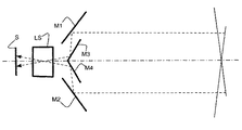
図1aは、画像センサSと、外部ミラーM1、M2および内部ミラーM3、M4とを備える獲得デバイスを示す。外部ミラーM1、M2および内部ミラーM3、M4は、角度調整がされて、かつレンズ系LSと関連付けられており、シーンの右立体画像Irおよび左立体画像IlをセンサS上に形成する。したがって、シーンのポイントPから放射された光線は、ミラーM1、M2、その後、ミラーM3、M4に投影され、光線がそこで焦点を結ぶレンズ系LSを横断して、2つの画像IrおよびIlをセンサS上に形成する。ミラーM1からM4は、45°の異なる角度に従って角度調整されて、右画像Irおよび左画像Ilが、センサSの2つの別個の連結した領域上に形成されることを可能にする(図1b)。 FIG. 1a shows an acquisition device comprising an image sensor S and external mirrors M1, M2 and internal mirrors M3, M4. The external mirrors M1 and M2 and the internal mirrors M3 and M4 are angle-adjusted and associated with the lens system LS, and form a right stereoscopic image Ir and a left stereoscopic image Il of the scene on the sensor S. Thus, the light rays emitted from the point P of the scene are projected onto the mirrors M1, M2 and then to the mirrors M3, M4, where the light rays traverse the lens system LS that focuses on the two images Ir and Il. Form on S. The mirrors M1 to M4 are angled according to different angles of 45 ° to allow the right image Ir and the left image Il to be formed on two separate connected regions of the sensor S (FIG. 1b). .
図1cは、図1aのデバイスの変形を示す。この変形も、画像IrおよびIlをセンサSの2つの別個の連結した領域上に形成することを可能にするが、これら2つの領域間の分離は、図1aのデバイスのものほどはっきりしておらず、これらの画像の被覆領域はより大きい。 FIG. 1c shows a variation of the device of FIG. 1a. This variant also allows the images Ir and Il to be formed on two separate connected areas of the sensor S, but the separation between these two areas is not as pronounced as that of the device of FIG. 1a. Rather, the coverage area of these images is larger.
これらの立体獲得デバイスにおけるミラーの使用は、画像IrおよびIlを幾何学的に歪ませる(キーストーニング(keystoning))。通常、これらの歪みは、これらの右画像および左画像を使用する前に補正される。 The use of mirrors in these stereo acquisition devices causes the images Ir and Il to be geometrically distorted (keystoneing). Usually, these distortions are corrected before using these right and left images.
これらの使用の1つは、上述のように幾何学的に補正された画像IrおよびIlから、奥行きマップ(depth map)とも呼ばれる、視差マップ(disparity map)を計算することである。 One of these uses is to calculate a disparity map, also called a depth map, from the images Ir and Il corrected as described above.
しかし、発明者は、わずかに凹凸がある画像領域では、この奥行きマップ計算の信頼性は高くないことを観察した。 However, the inventor has observed that the reliability of the depth map calculation is not high in an image region having slightly unevenness.
これらの領域におけるこの計算を信頼性の高いものにするための解決策の1つは、奥行きマップ計算デバイスを立体画像の獲得デバイス内に含むことである。 One solution to make this calculation in these regions reliable is to include a depth map calculation device in the stereoscopic image acquisition device.
構造化された光(以下、構造化光)の放射および受光に基づいた、知られている奥行きマップ計算デバイスの第1の例は、キャプチャするシーン上に構造化光を投影するのに適したプロジェクタと、シーン上へのこの投影から得られた反射画像をキャプチャするのに適した画像センサと、上述のようにキャプチャされた画像から奥行きマップを計算するための手段とを備える。 A first example of a known depth map calculation device based on the emission and reception of structured light (hereinafter structured light) is suitable for projecting structured light onto a scene to be captured A projector, an image sensor suitable for capturing a reflection image resulting from this projection onto the scene, and means for calculating a depth map from the captured image as described above.
知られている奥行きマップ計算デバイスの第2の例は、飛行時間(time of flight)に基づく。その原理は、持続時間が非常に短い光パルスをシーンに照射し、これらの光パルスが放射されてから、シーンの物体によって一度反射された後で獲得されるまでの移動に要した時間を測定するというものである。その後、各ピクセルの奥行きが、光線のこの帰還移動時間に従って計算される。このデバイスは、光パルスをシーンに照射するのに適したプロジェクタと、シーンのこの照射から得られる画像をキャプチャし、この画像のピクセル毎に、照射パルスがプロジェクタを出発してから、このパルスの光線がセンサに帰還するまでの間の時間シフトを測定するのに適した画像センサと、これらの時間シフトの測定値から奥行きマップを計算するための手段とを備える。 A second example of a known depth map calculation device is based on time of flight. The principle is that the scene is illuminated with light pulses of very short duration, and the time taken to travel after these light pulses are emitted and then once reflected by the object in the scene is measured. It is to do. The depth of each pixel is then calculated according to this return travel time of the ray. The device captures a projector suitable for illuminating the scene with a light pulse and an image resulting from this illumination of the scene, and for each pixel of the image, the illumination pulse leaves the projector and An image sensor suitable for measuring time shifts until the rays return to the sensor, and means for calculating a depth map from these time shift measurements.
奥行きマップを計算するためのこれらのデバイスの、構造化光またはパルス光のプロジェクタと画像センサは、補間(interpolation)分だけ互いに離れている。この補間は、センサの像平面の水平軸X上に表される水平成分だけを有するか、またはX軸に沿った水平成分とこの像平面のY軸上に表される垂直成分とを有する。 Of these devices for calculating depth maps, structured light or pulsed light projectors and image sensors are separated from each other by interpolation. This interpolation has only a horizontal component represented on the horizontal axis X of the sensor image plane, or has a horizontal component along the X axis and a vertical component represented on the Y axis of this image plane.
構造化光の放射および受光に基づいた奥行きマップ計算デバイスの場合、ピクセルの奥行きは、物体への構造化赤外光の投影によって形成された単一の画像から推定される(例えば、特許文献1を参照)。実際、像平面に直交するZ軸の方向にシーンの1地点から遠ざかると、X軸に沿った水平シフトを生じるので、画像においてX軸に沿ったこのシフトを測定すれば、所定の奥行きに配置されたパターンから獲得された赤外線画像と比較することによって、画像の各ピクセルの奥行きを決定することができる。 In the case of a depth map calculation device based on the emission and reception of structured light, the depth of a pixel is estimated from a single image formed by the projection of structured infrared light onto an object (e.g. See). In fact, moving away from one point in the scene in the direction of the Z-axis orthogonal to the image plane will cause a horizontal shift along the X-axis, so if you measure this shift along the X-axis in the image, place it at a given depth By comparing with the infrared image acquired from the acquired pattern, the depth of each pixel of the image can be determined.
したがって、立体画像獲得デバイスにおける奥行きマップ計算デバイスの導入は、従来技術によれば、立体画像獲得デバイスにおいて、とりわけプロジェクタと新しい画像センサの追加をもたらし、これらのデバイスのサイズを大きくする。 Accordingly, the introduction of depth map calculation devices in stereoscopic image acquisition devices, according to the prior art, results in the addition of projectors and new image sensors, in particular in stereoscopic image acquisition devices, increasing the size of these devices.
したがって、本発明によって解決される問題は、デバイスのサイズを著しく大きくすることなく、単一センサ立体画像獲得デバイスの奥行きマップの計算をより信頼性の高いものにすることである。 Therefore, the problem solved by the present invention is to make the calculation of the depth map of a single sensor stereoscopic image acquisition device more reliable without significantly increasing the size of the device.
この目的のもと、本発明は、センサと、図1a−cに関して説明されたように、シーンの右立体画像および左立体画像をセンサ上に形成するようにレンズ系と関連付けられた、外部ミラーおよび内部ミラーとを備える、立体画像獲得デバイスに関する。 For this purpose, the present invention relates to a sensor and an external mirror associated with a lens system to form a right and left stereoscopic image of the scene on the sensor, as described with respect to FIGS. 1a-c. And a stereoscopic image acquisition device comprising an internal mirror.
デバイスは、右立体画像および左立体画像が、これら2つの画像間に領域を空けて、センサ上に形成されるように、ミラーが角度調整され、一方では、構造化光またはパルス光を通過させ、他方では、シーンの物体上で一度反射された構造化光またはパルス光を通過させるように、スロットが内部ミラー間に形成され、前記領域上に前記反射された構造化光またはパルス光から画像を形成するようにスロットおよびレンズ系と関連付けられた光学部品をデバイスがさらに備えることを特徴とする。 The device allows the mirror to be angled so that the right and left stereo images are formed on the sensor with an area between the two images, while allowing structured light or pulsed light to pass. On the other hand, a slot is formed between the internal mirrors to pass the structured light or pulsed light once reflected on the object in the scene, and an image from the reflected structured light or pulsed light on the region The device further comprises optical components associated with the slot and lens system to form
上述の発明の特徴および他の特徴は、一実施形態についての以下の説明を読むことでより明白になり、前記説明は、添付の図面を参照して行われる。
本発明は、センサと、シーンの左立体画像および右立体画像を、レンズ系を通して、センサの感度表面の第1の領域および第2の領域上にそれぞれ形成するように角度調整された、外部ミラーおよび内部ミラーと、空間構造化光を前記シーン上に投影するのに適した、または光パルスを前記シーン上に投影するのに適した、プロジェクタと、投影された光によってもたらされるシーンの画像を、第1の領域と前記第2の領域の間に挿入された、センサの感度表面の第3の領域上に形成するようにレンズ系と関連付けられた光学部品と、光パルスを投影するのに適したプロジェクタの場合に、投影された光によってもたらされたこのキャプチャされた画像のピクセル毎に、プロジェクタからの光パルスの出発と前記センサへのこのパルスの帰還の間の時間シフトを測定する測定手段と、光パルスが投影された場合に、このキャプチャされた画像のピクセル毎の時間シフトの測定を介して、投影された光によってもたらされたこのキャプチャされた画像から奥行きマップを計算するための手段とを備える立体画像を獲得するためのデバイスであって、スロットが、一方では、プロジェクタによってシーン上に投影される光を通過させ、他方では、投影された光によってもたらされるシーンの画像を第3の領域上に形成するために必要な光を通過させるように、内部ミラー間に形成される、立体画像を獲得するためのデバイスにさらに関する。 The present invention provides an external mirror that is angularly adjusted to form a sensor and a left and right stereoscopic image of a scene through a lens system on a first area and a second area of the sensor's sensitivity surface, respectively. And an internal mirror, a projector suitable for projecting spatially structured light onto the scene, or suitable for projecting a light pulse onto the scene, and an image of the scene produced by the projected light An optical component associated with the lens system to be formed on a third region of the sensitivity surface of the sensor, inserted between the first region and the second region, and for projecting a light pulse. In the case of a suitable projector, for each pixel of this captured image brought by the projected light, the departure of the light pulse from the projector and the return of this pulse to the sensor The captured means brought by the projected light through the measurement means to measure the time shift between, and when the light pulse is projected, the measurement of the pixel-by-pixel time shift of this captured image A device for obtaining a stereoscopic image comprising means for calculating a depth map from an image, wherein the slot passes on one hand the light projected onto the scene by the projector and on the other hand is projected It further relates to a device for obtaining a stereoscopic image formed between the internal mirrors so as to pass the light necessary to form an image of the scene caused by the light on the third region.
好ましくは、第1の領域、第2の領域、および第3の領域は、重なり合わない。例えば、投影される光がIR光である場合、これは、センサのどのIR感知ピクセルも、文献(例えば、特許文献2を参照)に開示されているように(図3Dを参照)、可視光感知ピクセルR、G、Bと同じ領域に配置されないことを意味する。重なり合わない場合であっても、これらのゾーンは、センサの感度表面上で隣接することができる。 Preferably, the first region, the second region, and the third region do not overlap. For example, if the projected light is IR light, this means that any IR sensing pixel of the sensor is visible light as disclosed in the literature (see, eg, US Pat. It means that they are not arranged in the same area as the sensing pixels R, G, B. Even if they do not overlap, these zones can be adjacent on the sensitive surface of the sensor.
好ましくは、レンズ系と関連付けられた光学部品は、スロットとも関連付けられる。 Preferably, the optical component associated with the lens system is also associated with a slot.
ホイートストンの原理に基づいた従来のデバイスに施されるこの変更によって、別の光センサの追加を必要としない、空間構造化光またはパルス光の放射に基づいた、奥行きマップを計算するための方法を実施することができる。したがって、このデバイスのサイズの増加が大幅に抑制されることが分かる。 This change made to conventional devices based on the Wheatstone principle allows a method for calculating a depth map based on the emission of spatially structured light or pulsed light that does not require the addition of another light sensor. Can be implemented. Therefore, it can be seen that an increase in the size of the device is greatly suppressed.
さらに、デバイスは、奥行きマップの計算の信頼性を高めながらも、実装の平易性は維持するので、特に有利である。 Furthermore, the device is particularly advantageous because it increases the reliability of the depth map calculation while maintaining the simplicity of the implementation.
実際、従来技術の奥行きマップ計算デバイスは、国際出願(例えば、特許文献1を参照)のデバイスの場合、シーンの物体のエッジにおける光信号の検出の不安定性に起因する未定義領域、または図2および図3に示されるような投影に起因する影さえも有する奥行きマップを提供するという不都合を有する。 In fact, the prior art depth map calculation device, in the case of the device of the international application (see, for example, US Pat. No. 6,069,097), is an undefined region due to instability of detection of an optical signal at the edge of an object in the scene, or And has the disadvantage of providing a depth map with even shadows due to projection as shown in FIG.
図2および図3では、背景Bとこの背景の前方に配置された物体OBによるシーンが示されている。奥行きマップ計算デバイスは、赤外線センサIRSと、プロジェクタIRPから形成される。 2 and 3 show a scene with a background B and an object OB arranged in front of the background. The depth map calculation device is formed from an infrared sensor IRS and a projector IRP.
センサIRSとプロジェクタIRPは、センサIRSの像平面と平行な軸上に位置付けられ、X軸に沿って互いにずれている。その場合、未定義領域NDは、センサIRSから見えている。この未定義領域NDは、赤外光プロジェクタによって照射されないので、空間構造化光またはパルス光に基づいた方法によってはピクセルの奥行きを決定できない領域に対応するが、センサIRSから見えている。 The sensor IRS and the projector IRP are positioned on an axis parallel to the image plane of the sensor IRS and are shifted from each other along the X axis. In that case, the undefined area ND is visible from the sensor IRS. This undefined area ND corresponds to an area where the depth of the pixel cannot be determined by a method based on spatially structured light or pulsed light because it is not illuminated by an infrared projector, but is visible from the sensor IRS.
図3は、奥行きマップ計算デバイスが、とりわけ画像センサSを備える立体画像獲得デバイス内に含まれる場合を示している。このセンサSは、センサIRSとプロジェクタIRPの間のセンサIRSの像平面上に位置付けられる。したがって、図3から分かるように、未定義領域NDは、センサSから見えている。この未定義領域NDは、赤外光プロジェクタによって照射されないので、空間構造化光またはパルス光に基づいた方法によってはピクセルの奥行きを決定できない領域に対応するが、センサSから見えている。別の未定義領域ND1も、やはりセンサSから見えている。この未定義領域ND1は、赤外光プロジェクタによって照射されないので、構造化光に基づいた方法によってはピクセルの奥行きを決定できない領域に対応し、センサIRSから見えていない。 FIG. 3 shows the case where the depth map calculation device is included in a stereoscopic image acquisition device comprising an image sensor S among others. This sensor S is positioned on the image plane of the sensor IRS between the sensor IRS and the projector IRP. Therefore, as can be seen from FIG. 3, the undefined region ND is visible from the sensor S. Since this undefined area ND is not illuminated by the infrared projector, it corresponds to an area where the pixel depth cannot be determined by a method based on spatially structured light or pulsed light, but is visible from the sensor S. Another undefined area ND1 is also visible from the sensor S. Since this undefined area ND1 is not illuminated by the infrared light projector, it corresponds to an area in which the pixel depth cannot be determined by a method based on structured light, and is not visible from the sensor IRS.
したがって、X軸沿いの互いからある距離をおいたセンサSとプロジェクタIRPの位置は、センサSから見えるが、被写界深度(depth of field)を定義できない画像の領域を最小化するための適切な解決策ではない。 Therefore, the position of the sensor S and the projector IRP at a distance from each other along the X axis is suitable for minimizing the area of the image that is visible from the sensor S but that cannot define the depth of field. Is not a good solution.
好ましくは、レンズ系に関連付けられた光学部品とレンズ系は、スロットの中心とセンサの感度表面の第3の領域の中心を通る共通の光軸を有する。したがって、第3の領域の中心をデバイスの光軸が通り、投影された光によるシーンの照射によってもたらされる反射された構造化光は、スロットを通過して、デバイスのレンズ系に関連付けられた光学部品とレンズ系に共通する光軸に沿って獲得され、この光軸に関して(X軸に沿って)水平にずれた別のセンサによっては獲得されない。有利なことには、スロットおよび第3の領域の中心をこのように好ましく定めることによって、一方では、被写界深度を定義できない画像の領域を制限することができ、他方では、シーンの物体のエッジにおける光信号の検出の不安定性を制限することができる。したがって、奥行きマップの信頼性が、これによってしかるべく改善される。 Preferably, the optical component and lens system associated with the lens system have a common optical axis that passes through the center of the slot and the center of the third region of the sensitive surface of the sensor. Thus, the reflected structured light resulting from the illumination of the scene with the projected light passes through the center of the third region and the optical system associated with the lens system of the device. Acquired along an optical axis common to the component and lens system, and not acquired by another sensor that is horizontally offset (along the X axis) with respect to this optical axis. Advantageously, this preferred centering of the slot and the third region allows, on the one hand, limiting the region of the image for which the depth of field cannot be defined, while on the other hand the object of the scene The instability of detection of the optical signal at the edge can be limited. Thus, the reliability of the depth map is thereby improved accordingly.
好ましい一実施形態によれば、デバイスは、したがって、プロジェクタとセンサとを隔てる補間が水平成分を有さないようにセンサに対して位置付けられた、構造化光またはパルス光のプロジェクタを備える。より正確には、プロジェクタは、センサの感度表面の第3の領域の中心とこのプロジェクタの投影軸がこの感度表面の平面と交わる交点とを結ぶ直線が水平成分を有さない方式で構成される。言い換えると、プロジェクタは、好ましくは、センサの中心の上または下に配置される。 According to a preferred embodiment, the device therefore comprises a structured or pulsed light projector, positioned relative to the sensor such that the interpolation separating the projector and the sensor has no horizontal component. More precisely, the projector is configured in such a way that the straight line connecting the center of the third region of the sensor sensitivity surface and the intersection where the projection axis of the projector intersects the plane of the sensitivity surface does not have a horizontal component. . In other words, the projector is preferably placed above or below the center of the sensor.
この実施形態は、センサに対するプロジェクタのこの特定の位置が、被写界深度を定義できない画像の領域をまたさらに制限するので有利である。 This embodiment is advantageous because this particular position of the projector relative to the sensor further limits the area of the image where the depth of field cannot be defined.
構造化光またはパルス光が赤外線タイプである場合に関連する変形形態によれば、デバイスは、反射された構造化光またはパルス光をフィルタリングするための可視光のブロッキングフィルタをさらに備える。言い換えると、可視光のこのブロッキングフィルタは、投影された光によってもたらされるシーンの画像をセンサの感度表面の第3の領域上に形成するのに必要な光の経路上に位置付けられる。 According to a variant associated with the structured light or pulsed light being of the infrared type, the device further comprises a visible light blocking filter for filtering the reflected structured light or pulsed light. In other words, this blocking filter of visible light is positioned on the path of light necessary to form an image of the scene caused by the projected light on the third area of the sensor's sensitive surface.
変形形態によれば、デバイスは、右画像および左画像を形成するように意図された光をフィルタリングするための赤外線ブロッキングフィルタも備える。言い換えると、この赤外線ブロッキングフィルタは、右立体画像および左立体画像をセンサの感度表面の第1の領域および第2の領域上にそれぞれ形成するのに必要な光の経路上に位置付けられる。 According to a variant, the device also comprises an infrared blocking filter for filtering light intended to form a right image and a left image. In other words, the infrared blocking filter is positioned on the light path necessary to form the right and left stereoscopic images on the first and second areas of the sensor's sensitivity surface, respectively.
これらの変形形態は、右画像、左画像、および赤外線画像が、特にそれらのエッジにおいて互いに妨害しないようにすることができ、そのことが、これらの画像の使用を、特にセンサ上に形成された赤外線画像から奥行きマップを計算するための方法の実施を容易にするので有利である。 These variants can prevent the right image, the left image, and the infrared image from interfering with each other, especially at their edges, which has made the use of these images especially on the sensor This is advantageous because it facilitates the implementation of the method for calculating the depth map from the infrared image.
本発明による立体画像獲得デバイスは、図1a、図1b、および図1cにおいて説明されたホイートストン立体鏡の原理を使用するデバイスの変更バージョンである。 The stereoscopic image acquisition device according to the present invention is a modified version of the device that uses the Wheatstone stereoscopic mirror principle described in FIGS. 1a, 1b, and 1c.
実際、本発明によるデバイスは、画像センサSと、シーンの右立体画像Irおよび左立体画像IlをセンサS上に形成するように角度調整され、レンズ系LSと関連付けられた、外部画像M1、M2および内部画像M3、M4とを備える。 In fact, the device according to the present invention is an image sensor S and external images M1, M2 that are angularly adjusted to form a right stereoscopic image Ir and a left stereoscopic image Il of the scene on the sensor S and associated with the lens system LS. And internal images M3 and M4.
このデバイスは、右立体画像Irおよび左立体画像Ilが、通常の場合のように隣り合わせ(図1b)ではなく、これら2つの画像間に領域IRを空ける方式(図4b)でセンサ上に形成されるように、ミラーM1、M2、M3、M4が角度調整されるところが独特である。 In this device, the right stereoscopic image Ir and the left stereoscopic image Il are not adjacent to each other as in a normal case (FIG. 1b), but are formed on the sensor by a method (FIG. 4b) in which an area IR is provided between these two images. As described above, the mirrors M1, M2, M3, and M4 are unique in that the angle is adjusted.
さらに、デバイスの別の特徴によれば、スロットSが、一方では、プロジェクタIRPによって放射された構造化光を通過させ、他方では、シーンの物体上で一度反射された構造化光を通過させるように、内部ミラーM3とM4との間に形成される。 Further, according to another feature of the device, the slot S passes on the one hand the structured light emitted by the projector IRP and, on the other hand, the structured light once reflected on the object of the scene. Formed between the inner mirrors M3 and M4.
別の特徴によれば、デバイスは、したがって、前記領域IR上に前記反射された構造化光から画像を形成するようにスロットSlおよびレンズ系LSと関連付けられた光学部品ALを備える。 According to another characteristic, the device therefore comprises an optical component AL associated with the slot Sl and the lens system LS so as to form an image from the reflected structured light on the region IR.
したがって、デバイスによって立体画像を獲得しなければならない場合、プロジェクタIRPは、例えば赤外線タイプの構造化光を放射する。典型的には、右画像Irおよび左画像Ilは、外部ミラーおよび内部ミラーを介して、センサS上に形成される。シーンの物体上で反射された構造化光は、スロットSlを横断し、赤外線画像が、領域IR内に形成される。 Thus, when a stereoscopic image has to be acquired by the device, the projector IRP emits structured light, for example of infrared type. Typically, the right image Ir and the left image Il are formed on the sensor S via an external mirror and an internal mirror. The structured light reflected on the object in the scene traverses the slot Sl and an infrared image is formed in the region IR.
一実施形態によれば、プロジェクタIRPは、センサSに対して、それらを隔てる補間が水平成分を有さないように位置付けられる。したがって、プロジェクタIRPの光心とセンサSの光心は、(像平面のマーカのX軸に沿った)水平成分を有さない直線線分上に含まれる。 According to one embodiment, the projector IRP is positioned relative to the sensor S such that the interpolation separating them has no horizontal component. Accordingly, the optical center of the projector IRP and the optical center of the sensor S are included on a straight line segment having no horizontal component (along the X axis of the marker on the image plane).
構造化光が赤外線タイプである場合に関連する変形形態によれば、デバイスは、反射された構造化光をフィルタリングするための可視光のブロッキングフィルタをさらに備える。 According to a variant associated with the structured light being of the infrared type, the device further comprises a visible light blocking filter for filtering the reflected structured light.
変形形態によれば、デバイスは、右画像および左画像を形成するように意図された光をフィルタリングするための赤外線ブロッキングフィルタも備える。 According to a variant, the device also comprises an infrared blocking filter for filtering light intended to form a right image and a left image.
この最後の変形形態の一実施形態によれば、これらのフィルタは、2色性タイプである。 According to one embodiment of this last variant, these filters are of the dichroic type.
Claims (7)
レンズ系を介して前記センサの感度表面の第1の領域および第2の領域上にシーンの右立体画像及び左立体画像をそれぞれ形成するように角度調整された外部ミラー及び内部ミラーと、
空間構造化光を前記シーン上に投影するのに適した、または光パルスを前記シーン上に投影するのに適した、プロジェクタと、
前記投影された光から来る前記シーンの画像の形成を、前記センサの前記感度表面の第3の領域上に行うための前記レンズ系と関連付けられた光学部品であって、前記第3の領域が前記第1の領域及び前記第2の領域の間に挿入される、光学部品と、 光パルスを投影するのに適したプロジェクタの場合に、前記投影された光から来るこのキャプチャされた画像のピクセル毎に、前記プロジェクタからの光パルスの出発と前記センサへのこのパルスの帰還の間の時間シフトを測定する測定手段と、
光パルスが投影された場合に、このキャプチャされた画像のピクセル毎の時間シフトの前記測定を介して、このキャプチャされた画像から奥行きマップを計算するための手段と
を備える立体画像を獲得するためのデバイスにおいて、
一方では、前記プロジェクタによって前記シーン上に投影される前記光を通過させ、他方では、前記第3の領域上に投影される前記光から来る前記シーンの前記画像を形成するために必要となる前記光を通過させるためのスロットが、前記内部ミラー間に形成される
ことを特徴とするデバイス。 A sensor,
An external mirror and an internal mirror that are angle-adjusted to form a right stereoscopic image and a left stereoscopic image of the scene, respectively, on the first and second regions of the sensitivity surface of the sensor via a lens system;
A projector suitable for projecting spatially structured light onto the scene or suitable for projecting light pulses onto the scene;
An optical component associated with the lens system for forming an image of the scene coming from the projected light on a third region of the sensitive surface of the sensor, wherein the third region is This captured image pixel coming from the projected light in the case of an optical component inserted between the first region and the second region and a projector suitable for projecting a light pulse Measuring means for measuring the time shift between the start of a light pulse from the projector and the return of this pulse to the sensor,
For obtaining a stereoscopic image comprising means for calculating a depth map from the captured image via the measurement of the pixel-by-pixel time shift of the captured image when a light pulse is projected Devices
On the one hand, the light projected onto the scene by the projector is allowed to pass, and on the other hand, the image required for forming the image of the scene coming from the light projected onto the third region. A slot for passing light is formed between the inner mirrors.
Applications Claiming Priority (2)
| Application Number | Priority Date | Filing Date | Title |
|---|---|---|---|
| EP11306781.3A EP2611169A1 (en) | 2011-12-27 | 2011-12-27 | Device for the acquisition of stereoscopic images |
| EP11306781.3 | 2011-12-27 |
Publications (2)
| Publication Number | Publication Date |
|---|---|
| JP2013138434A true JP2013138434A (en) | 2013-07-11 |
| JP2013138434A5 JP2013138434A5 (en) | 2016-02-18 |
Family
ID=47323990
Family Applications (1)
| Application Number | Title | Priority Date | Filing Date |
|---|---|---|---|
| JP2012285452A Withdrawn JP2013138434A (en) | 2011-12-27 | 2012-12-27 | Device for acquisition of stereoscopic images |
Country Status (6)
| Country | Link |
|---|---|
| US (1) | US20140092219A1 (en) |
| EP (2) | EP2611169A1 (en) |
| JP (1) | JP2013138434A (en) |
| KR (1) | KR20130075700A (en) |
| CN (1) | CN103186029A (en) |
| BR (1) | BR102012033367A2 (en) |
Cited By (1)
| Publication number | Priority date | Publication date | Assignee | Title |
|---|---|---|---|---|
| CN107783353A (en) * | 2016-08-26 | 2018-03-09 | 光宝电子(广州)有限公司 | For catching the apparatus and system of stereopsis |
Families Citing this family (5)
| Publication number | Priority date | Publication date | Assignee | Title |
|---|---|---|---|---|
| EP2869263A1 (en) * | 2013-10-29 | 2015-05-06 | Thomson Licensing | Method and apparatus for generating depth map of a scene |
| KR102184042B1 (en) | 2014-01-29 | 2020-11-27 | 엘지이노텍 주식회사 | Camera apparatus |
| JP6493101B2 (en) * | 2015-09-01 | 2019-04-03 | オムロン株式会社 | Display device |
| CN107564051B (en) * | 2017-09-05 | 2020-06-02 | 歌尔股份有限公司 | Depth information acquisition method and system |
| FR3075738B1 (en) * | 2017-12-22 | 2020-11-27 | Valeo Comfort & Driving Assistance | VISUALIZATION SYSTEM, DASHBOARD INCLUDING SUCH A VISUALIZATION SYSTEM, AND CONSOLE FOR A VEHICLE INTERIOR INCLUDING SUCH VIEWING SYSTEM |
Family Cites Families (11)
| Publication number | Priority date | Publication date | Assignee | Title |
|---|---|---|---|---|
| US6587183B1 (en) * | 1998-05-25 | 2003-07-01 | Matsushita Electric Industrial Co., Ltd. | Range finder and camera |
| JP2003501635A (en) * | 1999-05-26 | 2003-01-14 | ローベルト ボッシュ ゲゼルシャフト ミット ベシュレンクテル ハフツング | Object detection system |
| JP2002236332A (en) * | 2001-02-09 | 2002-08-23 | Olympus Optical Co Ltd | Stereoscopic adapter, pattern projection adapter and adapter for light emitting member |
| JP3905736B2 (en) * | 2001-10-12 | 2007-04-18 | ペンタックス株式会社 | Stereo image pickup device and automatic congestion adjustment device |
| GB2388896A (en) * | 2002-05-21 | 2003-11-26 | Sharp Kk | An apparatus for and method of aligning a structure |
| JP4402400B2 (en) * | 2003-08-28 | 2010-01-20 | オリンパス株式会社 | Object recognition device |
| US8139141B2 (en) * | 2004-01-28 | 2012-03-20 | Microsoft Corporation | Single chip red, green, blue, distance (RGB-Z) sensor |
| CN101496033B (en) | 2006-03-14 | 2012-03-21 | 普莱姆森斯有限公司 | Depth-varying light fields for three dimensional sensing |
| US20070229850A1 (en) * | 2006-04-04 | 2007-10-04 | Boxternal Logics, Llc | System and method for three-dimensional image capture |
| EP2328337A4 (en) * | 2008-09-02 | 2011-08-10 | Huawei Device Co Ltd | 3d video communicating means, transmitting apparatus, system and image reconstructing means, system |
| KR101652393B1 (en) * | 2010-01-15 | 2016-08-31 | 삼성전자주식회사 | Apparatus and Method for obtaining 3D image |
-
2011
- 2011-12-27 EP EP11306781.3A patent/EP2611169A1/en not_active Withdrawn
-
2012
- 2012-12-14 EP EP12197125.3A patent/EP2611171A1/en not_active Withdrawn
- 2012-12-26 KR KR1020120153324A patent/KR20130075700A/en not_active Application Discontinuation
- 2012-12-27 US US13/727,695 patent/US20140092219A1/en not_active Abandoned
- 2012-12-27 BR BR102012033367-8A patent/BR102012033367A2/en not_active IP Right Cessation
- 2012-12-27 CN CN2012105992536A patent/CN103186029A/en active Pending
- 2012-12-27 JP JP2012285452A patent/JP2013138434A/en not_active Withdrawn
Cited By (2)
| Publication number | Priority date | Publication date | Assignee | Title |
|---|---|---|---|---|
| CN107783353A (en) * | 2016-08-26 | 2018-03-09 | 光宝电子(广州)有限公司 | For catching the apparatus and system of stereopsis |
| CN107783353B (en) * | 2016-08-26 | 2020-07-10 | 光宝电子(广州)有限公司 | Device and system for capturing three-dimensional image |
Also Published As
| Publication number | Publication date |
|---|---|
| US20140092219A1 (en) | 2014-04-03 |
| CN103186029A (en) | 2013-07-03 |
| EP2611169A1 (en) | 2013-07-03 |
| EP2611171A1 (en) | 2013-07-03 |
| KR20130075700A (en) | 2013-07-05 |
| BR102012033367A2 (en) | 2013-11-26 |
Similar Documents
| Publication | Publication Date | Title |
|---|---|---|
| JP2013138434A (en) | Device for acquisition of stereoscopic images | |
| EP3466061B1 (en) | Image projection system and image projection method | |
| AU2008244494B2 (en) | Single-lens 3-D imaging device using a polarization-coded aperture mask combined with a polarization-sensitive sensor | |
| US7826067B2 (en) | Method and apparatus for quantitative 3-D imaging | |
| JP6156724B2 (en) | Stereo camera | |
| JP2013138434A5 (en) | ||
| EP2813809A1 (en) | Device and method for measuring the dimensions of an objet and method for producing an item using said device | |
| KR20190098242A (en) | System for characterizing the environment around the vehicle | |
| JP2019139069A (en) | Projection system | |
| JP2012124766A5 (en) | ||
| US20180098053A1 (en) | Imaging device, endoscope apparatus, and imaging method | |
| JP6030471B2 (en) | Shape measuring device | |
| JP2006308323A (en) | Three-dimensional shape measuring method | |
| WO2016194179A1 (en) | Imaging device, endoscope and imaging method | |
| JP2010014505A (en) | Three-dimensional shape measuring apparatus and three-dimensional shape measurement method | |
| JP2014238299A (en) | Measurement device, calculation device, and measurement method for inspected object, and method for manufacturing articles | |
| JP6202364B2 (en) | Stereo camera and moving object | |
| JP2014238298A (en) | Measurement device, calculation device, and measurement method for inspected object, and method for manufacturing articles | |
| JP2007333525A (en) | Distance measurement device | |
| US10297020B2 (en) | Stereoscopic system and method for quality inspection of cigarettes in cigarette packer machines | |
| TW201426012A (en) | Display measuring device | |
| JP2018054454A5 (en) | ||
| JP2007057386A (en) | In-line three-dimensional measuring device and measuring method using one camera | |
| TW201807432A (en) | Image capturing device and image capturing method | |
| JPS6326522A (en) | Signal processing method for two-lens range finder device |
Legal Events
| Date | Code | Title | Description |
|---|---|---|---|
| A521 | Request for written amendment filed |
Free format text: JAPANESE INTERMEDIATE CODE: A523 Effective date: 20151224 |
|
| A621 | Written request for application examination |
Free format text: JAPANESE INTERMEDIATE CODE: A621 Effective date: 20151224 |
|
| A761 | Written withdrawal of application |
Free format text: JAPANESE INTERMEDIATE CODE: A761 Effective date: 20160229 |