JP2013132166A - Control device of electric vehicle - Google Patents
Control device of electric vehicle Download PDFInfo
- Publication number
- JP2013132166A JP2013132166A JP2011281171A JP2011281171A JP2013132166A JP 2013132166 A JP2013132166 A JP 2013132166A JP 2011281171 A JP2011281171 A JP 2011281171A JP 2011281171 A JP2011281171 A JP 2011281171A JP 2013132166 A JP2013132166 A JP 2013132166A
- Authority
- JP
- Japan
- Prior art keywords
- torque
- operation state
- motor
- brake
- braking
- Prior art date
- Legal status (The legal status is an assumption and is not a legal conclusion. Google has not performed a legal analysis and makes no representation as to the accuracy of the status listed.)
- Granted
Links
Images


Classifications
-
- Y—GENERAL TAGGING OF NEW TECHNOLOGICAL DEVELOPMENTS; GENERAL TAGGING OF CROSS-SECTIONAL TECHNOLOGIES SPANNING OVER SEVERAL SECTIONS OF THE IPC; TECHNICAL SUBJECTS COVERED BY FORMER USPC CROSS-REFERENCE ART COLLECTIONS [XRACs] AND DIGESTS
- Y02—TECHNOLOGIES OR APPLICATIONS FOR MITIGATION OR ADAPTATION AGAINST CLIMATE CHANGE
- Y02T—CLIMATE CHANGE MITIGATION TECHNOLOGIES RELATED TO TRANSPORTATION
- Y02T10/00—Road transport of goods or passengers
- Y02T10/60—Other road transportation technologies with climate change mitigation effect
- Y02T10/72—Electric energy management in electromobility
Abstract
Description
本発明は、電動車両の制御装置に関する。 The present invention relates to a control device for an electric vehicle.
特許文献1には、モータトルクからドラッグトルクを差し引いた有効トルクがギアバックラッシュメカニズムのゼロトルク区間へ進入する、またはゼロトルク区間から脱出すると判断した場合、制御時間を初期化しながら有効トルクを放物線または指数関数形態のトルクに制限することで、ギアバックラッシュ振動を低減する技術が開示されている。
In
しかしながら、上記従来技術にあっては、トルクが所定時間制限されるため、運転者の加速要求に応じた加速性能が得られないという問題があった。
本発明の目的は、運転者の加速要求に応じた加速性能を実現できる電動車両の制御装置を提供することにある。
However, the conventional technology has a problem that the acceleration performance according to the driver's acceleration request cannot be obtained because the torque is limited for a predetermined time.
The objective of this invention is providing the control apparatus of the electric vehicle which can implement | achieve the acceleration performance according to the driver | operator's acceleration request.
本発明の電動車両の制御装置では、ブレーキ操作状態が操作状態から非操作状態に変化したことが検出されてからアクセル操作が検出されるまでの間に、制動力発生部と電動モータを作動させてコースト走行状態を発生させる。 In the control apparatus for an electric vehicle according to the present invention, the braking force generation unit and the electric motor are operated during a period from when it is detected that the brake operation state is changed from the operation state to the non-operation state until the accelerator operation is detected. To generate a coasting condition.
よって、本発明の電動車両の制御装置では、運転者の加速要求に応じた加速性能を実現できる。 Therefore, the control device for an electric vehicle according to the present invention can realize acceleration performance according to the driver's acceleration request.
以下、本発明の電動車両の制御装置を実施するための形態を、図面に示す実施例に基づいて説明する。
〔実施例1〕
まず、構成を説明する。
図1は、実施例1の電動車両のシステム構成図である。
実施例1の電動車両は、正負のトルク(駆動トルク、制動トルク)を発生させる電動モータ(以下、モータ)100を備える。モータ100には、回転センサ101としてレゾルバが接続され、モータコントローラ102は、回転センサ101の情報を参照してインバータ103に駆動信号を出力する。インバータ103は、駆動信号に応じた電流をモータ100に供給し、モータトルクを制御する。
モータ100の出力軸100aは減速機(歯車伝達機構)104に接続され、ディファレンシャルギア(歯車伝達機構)105を介して車軸106にトルクを伝達する。モータ100を駆動する電力は高電圧バッテリ107から供給される。高電圧バッテリ107はバッテリコントローラ108によって充電状態や発熱の程度を監視されている。高電圧バッテリ107にはDC-DCコンバータ109が接続され、DC-DCコンバータ109により電圧を降圧して低電圧バッテリ110を充電する。
車両コントローラ(コントロールユニット)111は、図外のブレーキペダルおよびアクセルペダルのストローク(操作量)をブレーキストロークセンサ(ブレーキ操作状態検出部)111aおよびアクセルストロークセンサ(アクセル操作状態検出部)111bによって監視しており、ストロークに応じた正または負のトルク指令を、車内通信ライン112を経由して制動制御装置113に伝達する。
EMBODIMENT OF THE INVENTION Hereinafter, the form for implementing the control apparatus of the electric vehicle of this invention is demonstrated based on the Example shown on drawing.
[Example 1]
First, the configuration will be described.
FIG. 1 is a system configuration diagram of an electric vehicle according to a first embodiment.
The electric vehicle according to the first embodiment includes an electric motor (hereinafter referred to as a motor) 100 that generates positive and negative torques (drive torque and braking torque). A resolver is connected to the motor 100 as the
An output shaft 100a of the motor 100 is connected to a speed reducer (gear transmission mechanism) 104, and transmits torque to the axle 106 via a differential gear (gear transmission mechanism) 105. Electric power for driving the motor 100 is supplied from the
The vehicle controller (control unit) 111 monitors the strokes (operation amounts) of the brake pedal and accelerator pedal (not shown) by a brake stroke sensor (brake operation state detection unit) 111a and an accelerator stroke sensor (acceleration operation state detection unit) 111b. Thus, a positive or negative torque command corresponding to the stroke is transmitted to the
制動制御装置113は、各車輪FL,FR,RL,RRに設けた各車輪速度センサ114a,114b,114c,114dからの各車輪速情報やモータコントローラ102が出力するモータトルク情報から、駆動スリップ防止制御(TCS制御)や制動スリップ防止制御(ABS制御)等のトルク制御を行う。
制動制御装置113は、摩擦ブレーキトルクを制御する場合、運転者のペダル踏力に応じて制動制御装置113内のポンプ(不図示)を作動させて油圧配管115を通して各車輪FL,FR,RL,RRに設けた各ブレーキキャリパ116a,116b,116c,116dにブレーキ液を送り摩擦ブレーキトルクを発生させる。一方、モータトルクを制御する場合、車内通信ライン112によってモータコントローラ102にトルク指令を与える。
制動制御装置113と各ブレーキキャリパ116a,116b,116c,116dは、車輪FL,FR,RL,RRに制動力を与える摩擦ブレーキ(制動力発生部)を構成する。
The
When the
The
図2は、車両コントローラ111の制駆動トルク指令値算出制御ブロック図である。図2の制御ブロック111cは、ブレーキストロークセンサ111aによりブレーキ操作状態が操作状態から非操作状態に変化したことが検出されてからアクセルストロークセンサ111bによりアクセル操作が検出されるまでの間に、摩擦ブレーキとモータ100を作動させてコースト走行状態を発生させるコースト走行発生部に相当する。
アクセルによるモータトルク指令値算出部200は、アクセル操作量と車両速度とシフト位置とに基づいてモータトルク指令基準値を算出する。図3は、アクセルによるモータトルク指令値算出部200のモータトルク指令基準値算出制御ブロック図である。モータトルク指令基準値は、アクセル操作量が大きいほど、車両速度が低いほど、駆動トルクを大きくする。また、アクセル操作量がゼロの場合、車両速度が所定の速度(例えば、5km/h)以下である停車および低速領域では、オートマチックトランスミッション車のクリープトルクを模擬するために車両速度が低いほど駆動トルクを大きくし、車両速度が前記所定の速度を超える速度領域では、コースト走行状態におけるエンジンブレーキトルクを模擬するために回生ブレーキトルクを与える。なお、シフト位置がリバースの場合は逆となる。アクセル操作用およびモータ回転速度に応じたモータトルク指令基準値は、シフト位置毎や走行モード(スポーツモード、エコモード等)毎にあらかじめマップとして設定されている。
ブレーキによる車軸トルク指令値算出部201は、ブレーキ操作量に基づいて摩擦ブレーキトルク指令基準値を算出する。摩擦ブレーキトルク指令基準値は、ブレーキ操作量が大きいほど制動トルクを大きくする。
FIG. 2 is a block diagram of the braking / driving torque command value calculation control of the
The accelerator motor torque command
Axle torque command
回生摩擦ブレーキ配分部202は、車両速度に基づき、摩擦ブレーキトルク指令基準値を制動力指令摩擦ブレーキトルク成分と制動力指令モータトルク成分とに配分する。図4は、回生摩擦ブレーキ配分部202の回生摩擦ブレーキ配分の制御ブロック図であり、摩擦ブレーキトルク指令基準値と車両速度に応じたモータトルク制限値とを比較し、値が大きい方、すなわち絶対値が小さい方の値を制動力指令モータトルク成分とし、摩擦ブレーキトルク指令基準値から制動力指令モータトルク成分を減じた値を制動力指令摩擦ブレーキトルク成分とする。車両速度に応じたモータトルク制限値は、モータ100が発生可能な最大回生トルクとする。ここで、最大回生トルクは、車体速度、高電圧バッテリ107のバッテリSOC等により算出できる。例えば、回生不能領域である停車、低速領域およびインバータ103が過負荷となる高速領域では最大回生トルクをゼロとする。
運転者要求モータトルク算出部203は、モータトルク指令基準値に制動力指令モータトルク成分を加算して運転者要求モータトルクを算出する。
The regenerative friction
The driver request motor
モータトルク指令下限値算出部204は、運転者要求モータトルク、ブレーキ温度、シフト位置、ブレーキ操作量およびモータトルク指令値に基づいてトルク指令下限値を算出する。図5は、モータトルク指令下限値算出部204によるトルク指令下限値算出制御処理の流れを示すフローチャートで、以下、各ステップについて説明する。
ステップS501では、走行モードとしてスポーツモードが選択されている場合はステップS502へ進み、それ以外のモードが選択されている場合はステップS506へ進む。
ステップS502では、ブレーキが高温状態でない場合はステップS503へ進み、ブレーキが高温状態である場合はステップS506へ進む。
ステップS503では、ブレーキ操作なしの場合はステップS504へ進み、ブレーキ操作ありの場合はステップS506へ進む。
ステップS504では、モータトルク指令値が所定値未満の場合はステップS505へ進み、トルク指令値が所定値以上の場合はステップS506へ進む。
ステップS505では、モータトルク指令前回値(前制御周期のトルク指令値)に所定トルク変化量を加算した値と所定トルク値(駆動トルク)とを比較し、値の小さな方をトルク指令下限値とする。
ステップS506では、運転者要求モータトルクと出力可能最低トルクとを比較し、値の大きな方をトルク指令下限値とする。
The motor torque command lower
In step S501, if the sport mode is selected as the travel mode, the process proceeds to step S502, and if any other mode is selected, the process proceeds to step S506.
In step S502, if the brake is not in a high temperature state, the process proceeds to step S503, and if the brake is in a high temperature state, the process proceeds to step S506.
In step S503, if the brake operation is not performed, the process proceeds to step S504, and if the brake operation is performed, the process proceeds to step S506.
In step S504, if the motor torque command value is less than the predetermined value, the process proceeds to step S505, and if the torque command value is greater than the predetermined value, the process proceeds to step S506.
In step S505, the value obtained by adding the predetermined torque change amount to the previous value of the motor torque command (torque command value in the previous control cycle) is compared with the predetermined torque value (drive torque), and the smaller value is determined as the torque command lower limit value. To do.
In step S506, the driver request motor torque is compared with the minimum torque that can be output, and the larger value is set as the torque command lower limit value.
モータトルク選択部205は、運転者要求モータトルクとトルク指令下限値とを比較し、値の大きな方を下限値制限後のモータトルク指令値として出力する。
モータトルク比較部206は、運転者要求モータトルクから下限値制限後のモータトルク指令値を減算する。
バックラッシュ振動抑制トルク指令値変化量制限部(モータトルク変化量制限制御部)207は、通常時は下限値制限後のモータトルク指令値をそのままモータトルク指令値として出力するが、モータトルクがギアバックラッシュメカニズムのゼロトルク区間へ進入する、またはゼロトルク区間から脱出するゼロトルク通過時、下限値制限後のモータトルク指令値とモータトルク指令値とを入力し、下記に示すようなロジックに基づいてモータトルク指令値を算出する。
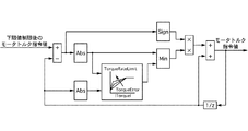
図6は、ゼロトルク通過時におけるバックラッシュ振動抑制トルク指令値変化量制限部207のモータトルク指令値算出制御ブロック図である。図6のブロックのうち、「Abs」は入力の絶対値を出力し、「Sign」は符号信号(正=1、負=-1)を出力する。「Min」は入力のうち小さい値を出力し、「1/Z」は1制御周期前の値を保存する。つまり、バックラッシュ振動抑制トルク指令値変化量制限部207は、下限値制限後のモータトルク指令値とモータトルク指令前回値との差分、すなわちトルクの単位時間当たりの増加量の上限を、図7に示すマップから算出したトルク変化量制限値で制限し、その値をモータトルク指令前回値に加えてトルク指令値とする。図7のマップは二次元マップであり、トルク指令絶対値(モータトルク指令前回値の絶対値)およびトルク偏差(下限値制限後のモータトルク指令値とモータトルク指令前回値との差分の絶対値)を入力する。このとき、算出するトルク変化量制限値は、トルク指令絶対値が小さいほど小さく、トルク偏差が小さいほど小さく設定する。
算出されたモータトルク指令値は、車内通信ライン112を経由してモータコントローラ102へと送られる。
摩擦ブレーキトルク指令値算出部208は、運転者要求モータトルクから下限値制限後のモータトルク指令値を減算した値を制動力指令摩擦ブレーキトルク成分に加算して摩擦ブレーキトルク指令値を算出する。
算出された摩擦ブレーキトルク指令値は、車内通信ライン112を経由して制動制御装置113へと送られる。
The motor
The motor
The backlash vibration suppression torque command value change amount restriction unit (motor torque change amount restriction control unit) 207 normally outputs the motor torque command value after the lower limit value restriction as it is as the motor torque command value. When the zero torque passing through the zero torque section of the backlash mechanism or passing through the zero torque section is passed, the motor torque command value and the motor torque command value after the lower limit limit are input, and the motor torque is based on the logic as shown below Calculate the command value.
FIG. 6 is a block diagram of the motor torque command value calculation control of the backlash vibration suppression torque command value change
The calculated motor torque command value is sent to the
The friction brake torque command
The calculated friction brake torque command value is sent to the
次に、作用を説明する。
[ギアバックラッシュ振動抑制作用]
図8は、実施例1の比較例として、図2からモータトルク指令下限値算出部204、モータトルク選択部205、モータトルク比較部206、摩擦ブレーキトルク指令値算出部208を除いた構成を想定し、バックラッシュ振動抑制トルク指令値変化量制限部207によるバックラッシュ振動抑制トルク指令値変化量制限制御のみを実施した場合のタイムチャートである。この比較例では、バックラッシュ振動抑制トルク指令値変化量制限部207には運転者要求モータトルクが入力され、制動力指令摩擦ブレーキトルク成分はそのまま摩擦ブレーキトルク指令値となる。
図8に示すように、比較例では、車両走行中にアクセルペダルを離した場合に生じるエンジンブレーキ相当の制動トルクから、再度アクセルペダルを操作して加速に転じる、すなわち駆動トルクを要求する場合、アクセル操作量に応じたトルク変化量制限値によってモータトルクの単位時間当たりの増加量を制限する。よって、トルク変化量制限制御なしの場合と比較して、ゼロトルク通過時のトルク変化量(トルクの上昇勾配)が小さく抑えられるため、ギアバックラッシュ振動の低減を図ることができる。
Next, the operation will be described.
[Gear backlash vibration suppression action]
FIG. 8 assumes a configuration in which the motor torque command lower limit
As shown in FIG. 8, in the comparative example, when the accelerator pedal is operated again and turned to acceleration from the braking torque equivalent to the engine brake generated when the accelerator pedal is released during vehicle traveling, that is, when driving torque is requested, The increase amount per unit time of the motor torque is limited by the torque change amount limit value corresponding to the accelerator operation amount. Therefore, compared to the case without the torque change amount limiting control, the torque change amount when the zero torque passes (torque increase gradient) can be suppressed to be small, so that the gear backlash vibration can be reduced.
このとき、実施例1のバックラッシュ振動抑制トルク指令値変化量制限制御では、運転者が要求するトルクの上昇勾配が大きく、またアクセルペダルの踏み込み量も大きいときには、図7に示したマップに従ってトルク変化量制限値は大きな値が選択されるので、緩やかにアクセルペダルを操作する場合と比較してトルク上昇勾配は大きくなる。つまり、運転者に急加速の意図がある場合には、ギアバックラッシュ振動の低減効果を低下させる代わりに運転者の加速要求に対する遅れ時間を短くすることができる。このとき、ギアバックラッシュ振動は生じるが、急加速中であるため運転者に違和感を与えることはない。
一方、運転者が要求するトルクの上昇勾配が小さければ、図7に示したマップ入力のトルク偏差が大きくならないため、トルク変化量制限値は小さくなる。これにより、運転者が緩やかな加速を望んでいる場合には小さな変化量でゼロトルクを通過するようになるため、ギアバックラッシュ振動の抑制効果を十分に得られる。
At this time, in the backlash vibration suppression torque command value change amount limiting control according to the first embodiment, when the torque increase gradient requested by the driver is large and the accelerator pedal depression amount is large, the torque according to the map shown in FIG. Since a large value is selected as the change amount limit value, the torque increase gradient becomes larger than when the accelerator pedal is gently operated. That is, when the driver intends to accelerate rapidly, the delay time with respect to the driver's acceleration request can be shortened instead of reducing the reduction effect of the gear backlash vibration. At this time, gear backlash vibration is generated, but the driver is not feeling uncomfortable because of rapid acceleration.
On the other hand, if the torque increase gradient required by the driver is small, the torque deviation of the map input shown in FIG. 7 does not increase, and the torque change amount limit value decreases. Thus, when the driver desires gentle acceleration, zero torque is passed with a small amount of change, so that the effect of suppressing gear backlash vibration can be sufficiently obtained.
[トルク応答性向上作用]
上記のようなバックラッシュ振動抑制トルク指令値変化量制限制御を実施することで、加速要求に合致したトルクの応答性とギアバックラッシュ振動の抑制効果との両立を実現できるが、運転者のアクセル操作に対してモータ100の応答に必ず遅れが生じてしまう。特に、運転者が走行モードとしてスポーツモードを選択している場合、アクセル操作に対するトルクの応答性が悪いと、運転者の加速要求に応じた加速性能が得られず、違和感を与えてしまう。
これに対し、実施例1では、スポーツモードが選択されている場合、ブレーキ操作ありの状態からブレーキ操作なしの状態に変化した後、アクセル操作が検出されるまでの間に、摩擦ブレーキを作動させてコースト走行状態、すなわちエンジンブレーキ相当の制動トルクを発生させるブレーキ協調制御を実施する。
これにより、モータ100の回生ブレーキトルクによってエンジンブレーキ相当の制動トルクを発生させる必要がないため、運転者がアクセル操作を開始する前にモータトルクを制動トルクから駆動トルクへと移行させゼロトルクを通過させておくことができる。よって、アクセル操作中にトルク変化量を制限する必要がないため、アクセル操作に対してモータ100の駆動トルクを遅れなく追従させることができる。
なお、高い加速性能が要求されるスポーツモード以外の走行モードが選択されている場合、上記ブレーキ協調制御は実施しない。ブレーキ協調制御では、通常の回生ブレーキトルクによるエンジンブレーキトルクの模擬に代えて、摩擦ブレーキによるエンジンブレーキトルクの模擬を行うため、コースト走行時の回生効率が低下するからである。
[Torque response improvement]
By implementing the backlash vibration suppression torque command value variation limit control as described above, it is possible to achieve both the torque response that matches the acceleration request and the effect of suppressing the gear backlash vibration. There is always a delay in the response of the motor 100 to the operation. In particular, when the driver selects the sport mode as the travel mode, if the torque responsiveness to the accelerator operation is poor, the acceleration performance according to the driver's acceleration request cannot be obtained, giving a sense of incongruity.
On the other hand, in the first embodiment, when the sport mode is selected, the friction brake is operated after the change from the state with the brake operation to the state without the brake operation until the accelerator operation is detected. Then, the brake cooperative control is performed to generate a coasting state, that is, a braking torque corresponding to the engine brake.
As a result, it is not necessary to generate a braking torque equivalent to the engine brake by the regenerative braking torque of the motor 100, so that the motor torque is shifted from the braking torque to the driving torque and the zero torque is passed before the driver starts the accelerator operation. I can keep it. Therefore, since it is not necessary to limit the amount of torque change during the accelerator operation, the driving torque of the motor 100 can follow the accelerator operation without delay.
It should be noted that the brake cooperative control is not performed when a travel mode other than the sport mode that requires high acceleration performance is selected. This is because in the brake cooperative control, instead of simulating the engine brake torque by the normal regenerative brake torque, the engine brake torque by the friction brake is simulated, so that the regenerative efficiency during coasting decreases.
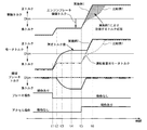
図9は、実施例1のブレーキ協調制御によるトルク応答性向上作用を示すタイムチャートである。走行モードとしてスポーツモードが選択されているものとする。
時点t1では、ブレーキ操作ありの状態からブレーキ操作なしの状態へと移行したため、図5のフローチャートにおいて、S501→S502→S503→S506の流れからS501→S502→S503→S504→S505の流れに切り替わり、モータトルク指令値は、モータトルク指令前回値に所定トルク変化量を加算した値となる。また、運転者要求モータトルクは、エンジンブレーキ相当の制動トルクとなるため、摩擦ブレーキトルク指令値は、エンジンブレーキ相当の制動トルクからトルク指令下限値を減じた値となる。
時点t1からt2までの期間では、モータトルクはトルク指令下限値に沿って徐々に上昇する(ゼロに近づいていく)ため、車軸トルクはエンジンブレーキ相当の制動トルクへと近づく。
時点t2では、車輪に作用する車軸トルクがエンジンブレーキ相当の制動トルクとなる。
時点t2からt3までの期間では、モータトルクの上昇に応じて摩擦ブレーキトルクが徐々に増大するため、車軸トルクはエンジンブレーキ相当の制動トルクに維持される。なお、時点t2からt3までの区間において、モータトルク(有効トルク)がギアバックラッシュメカニズムのゼロトルク区間へ進入したとき、バックラッシュ振動抑制トルク指令値変化量制限制御が作動するため、モータトルク指令値の単位時間当たりの変化量は、所定トルク変化量よりも小さく制限される。
FIG. 9 is a time chart illustrating the torque response improvement effect by the brake cooperative control of the first embodiment. It is assumed that the sport mode is selected as the travel mode.
At time t1, since the state with the brake operation is shifted to the state without the brake operation, the flow from S501 → S502 → S503 → S506 is switched to the flow S501 → S502 → S503 → S504 → S505 in the flowchart of FIG. The motor torque command value is a value obtained by adding a predetermined torque change amount to the previous value of the motor torque command. Further, since the driver-requested motor torque is a braking torque equivalent to the engine brake, the friction brake torque command value is a value obtained by subtracting the torque command lower limit value from the braking torque equivalent to the engine brake.
In the period from time t1 to t2, the motor torque gradually increases (approaches zero) along the torque command lower limit value, so that the axle torque approaches a braking torque equivalent to the engine brake.
At time t2, the axle torque acting on the wheels becomes a braking torque equivalent to engine braking.
In the period from time t2 to t3, the friction brake torque gradually increases as the motor torque increases, so the axle torque is maintained at the braking torque equivalent to the engine brake. Note that when the motor torque (effective torque) enters the zero torque section of the gear backlash mechanism in the section from time t2 to t3, the backlash vibration suppression torque command value change limit control is activated, so the motor torque command value The amount of change per unit time is limited to be smaller than the predetermined torque change amount.
時点t3では、モータトルクがゼロトルクを通過するが、モータトルクの単位時間当たりの変化量を制限しているため、ギアバックラッシュ振動を運転者に違和感を与えないレベルまで低減できる。
時点t3からt4までの期間において、モータトルクがギアラックラッシュメカニズムのゼロトルク区間から脱出したとき、バックラッシュ振動抑制トルク指令値変化量制限制御が非作動となる。
時点t5では、運転者がアクセル操作を開始したため、図5のフローチャートにおいて、S501→S502→S503→S504→S505の流れからS501→S502→S503の流れに切り替わり、モータトルク指令値は、アクセル操作に応じた運転者要求モータトルクとなる。また、ブレーキペダルは操作されていないため、摩擦ブレーキトルク指令値はゼロとなる。
時点t5からt6までの期間では、摩擦ブレーキトルクがゼロとなり、モータトルクはアクセル操作に応じた運転者要求モータトルクと同じ勾配で上昇するため、車軸トルクはモータトルクとほぼ同じ勾配で上昇する。
At time t3, the motor torque passes through zero torque, but since the amount of change in motor torque per unit time is limited, the gear backlash vibration can be reduced to a level that does not give the driver a sense of incongruity.
During the period from time t3 to t4, when the motor torque escapes from the zero torque section of the gear lash crush mechanism, the backlash vibration suppression torque command value change limit control is deactivated.
At time t5, since the driver has started the accelerator operation, in the flowchart of FIG. 5, the flow from S501 → S502 → S503 → S504 → S505 is switched to the flow S501 → S502 → S503, and the motor torque command value is changed to the accelerator operation. The corresponding driver request motor torque is obtained. Further, since the brake pedal is not operated, the friction brake torque command value becomes zero.
In the period from the time point t5 to the time point t6, the friction brake torque is zero, and the motor torque increases with the same gradient as the driver-requested motor torque according to the accelerator operation. Therefore, the axle torque increases with substantially the same gradient as the motor torque.
ここで、比較例では、ゼロトルク通過時に変化量を制限しているため、アクセル操作に対するモータトルクの応答性が悪く、運転者の加速要求に応じた加速性能が得られなかったのに対し、実施例1では、運転者のアクセル操作前にゼロトルクを通過させるため、運転者のアクセル操作中にトルク変化量を制限する必要がなく、運転者の加速要求に応じた加速性能を実現できる。
また、ゼロトルク通過時はバックラッシュ振動抑制トルク指令値変化量制限制御によりトルクの変化量を制限するため、ギアバックラッシュ振動を運転者に違和感を与えないレベルまで低減できる。
さらに、モータトルクを所定トルク値まで高める際、車軸トルクがエンジンブレーキ相当の制動トルクを維持するように、すなわち、車軸トルクが変動しないように、モータトルクの変化に合わせて摩擦ブレーキトルクを調整するため、車両の減速度の変動に伴う違和感を軽減できる。
さらに、実施例1では、アクセル操作が検出された場合、摩擦ブレーキトルクをゼロにするため、摩擦ブレーキによる制動トルクによって車両の加速性能が悪化するのを抑制できる。
Here, in the comparative example, since the amount of change is limited when zero torque passes, the motor torque response to the accelerator operation is poor, and the acceleration performance according to the driver's acceleration request was not obtained. In Example 1, since zero torque is passed before the driver's accelerator operation, there is no need to limit the amount of torque change during the driver's accelerator operation, and acceleration performance according to the driver's acceleration request can be realized.
Further, since the amount of torque change is limited by the backlash vibration suppression torque command value change amount limiting control when the zero torque is passed, the gear backlash vibration can be reduced to a level that does not cause the driver to feel uncomfortable.
Further, when the motor torque is increased to a predetermined torque value, the friction brake torque is adjusted in accordance with the change of the motor torque so that the axle torque maintains a braking torque equivalent to the engine brake, that is, the axle torque does not fluctuate. Therefore, it is possible to reduce a sense of incongruity associated with fluctuations in vehicle deceleration.
Furthermore, in the first embodiment, when the accelerator operation is detected, the friction brake torque is set to zero, so that it is possible to suppress the deterioration of the acceleration performance of the vehicle due to the braking torque by the friction brake.
次に、効果を説明する。
実施例1の電動車両の制御装置にあっては、以下に列挙する効果を奏する。
(1) 車輪FL,FR,RL,RRに制動力を与える摩擦ブレーキ(制動制御装置113、各ブレーキキャリパ116a,116b,116c,116d)と、運転者のブレーキ操作状態を検出するブレーキストロークセンサ111aと、運転者のアクセル操作状態を検出するアクセルストロークセンサ111bと、歯車伝達機構(減速機104、ディファレンシャルギア105)を介して接続された車輪FL,FR,RL,RRに対して制駆動トルクを与えるモータ100と、アクセルストロークセンサ111bによって検出されたアクセル操作量に基づいてモータ100を制駆動するためのモータトルク指令値を算出する車両コントローラ111と、を備え、車両コントローラ111は、ブレーキストロークセンサ111aによりブレーキ操作状態が操作状態から非操作状態に変化したことが検出されてからアクセルストロークセンサ111bによりアクセル操作が検出されるまでの間に、摩擦ブレーキとモータ100を作動させてコースト走行状態を発生させるコースト走行発生部111cを備えた。
よって、運転者の加速要求に応じた加速性能を実現できる。
(2) 車両コントローラ111は、モータ100のトルクが制動トルクから駆動トルクへ切り替わる際にモータトルク指令値に基づき駆動されるモータ100のトルクの単位時間当たりの増加量を制限するバックラッシュ振動抑制トルク指令値変化量制限部207を備え、コースト走行発生部111cは、バックラッシュ振動抑制トルク指令値変化量制限部207により制限されたモータ100による駆動トルクと摩擦ブレーキによる制動トルクとによりコースト走行状態を発生させる。
よって、ギアバックラッシュ振動を運転者に違和感を与えないレベルまで低減できると共に、車両の減速度の変動に伴う違和感を軽減できる。
(3) コースト走行発生部111cは、アクセルストロークセンサ111bによりアクセル操作状態が検出されると、摩擦ブレーキによる制動力をゼロとする。
よって、アクセル操作の開始時、摩擦ブレーキによる制動トルクによって車両の加速性能が悪化するのを抑制できる。
Next, the effect will be described.
The control device for an electric vehicle according to the first embodiment has the following effects.
(1) Friction brakes (
Therefore, acceleration performance according to the driver's acceleration request can be realized.
(2) The
Therefore, the gear backlash vibration can be reduced to a level that does not give the driver a sense of incongruity, and the sense of incongruity associated with fluctuations in the deceleration of the vehicle can be reduced.
(3) When the accelerator operation state is detected by the
Therefore, it is possible to suppress the deterioration of the acceleration performance of the vehicle due to the braking torque by the friction brake at the start of the accelerator operation.
100 電動モータ
104 減速機(歯車伝達機構)
105 ディファレンシャルギア(歯車伝達機構)
111 車両コントローラ(コントロールユニット)
111a ブレーキストロークセンサ(ブレーキ操作状態検出部)
111b アクセルストロークセンサ(アクセル操作状態検出部)
111c コースト走行発生部
113 制動制御装置(制動力発生部)
116a,116b,116c,116d 各ブレーキキャリパ(制動力発生部)
207 バックラッシュ振動抑制トルク指令値変化量制限部(モータトルク変化量制限制御部)
FL,FR,RL,RR 各車輪
100 electric motor
104 Reducer (gear transmission mechanism)
105 Differential gear (gear transmission mechanism)
111 Vehicle controller (control unit)
111a Brake stroke sensor (brake operation state detector)
111b Accelerator stroke sensor (Accelerator operation state detector)
111c Coast running generator
113 Braking control device (braking force generator)
116a, 116b, 116c, 116d Brake calipers (braking force generator)
207 Backlash vibration suppression torque command value change amount limiting unit (Motor torque change amount limiting control unit)
FL, FR, RL, RR each wheel
Claims (3)
運転者のブレーキ操作状態を検出するブレーキ操作状態検出部と、
運転者のアクセル操作状態を検出するアクセル操作状態検出部と、
歯車伝達機構を介して接続された車輪に対して制駆動トルクを与える電動モータと、
前記アクセル操作量検出部によって検出されたアクセル操作量に基づいて前記電動モータを制駆動するためのモータトルク指令値を算出するコントロールユニットと、
を備え、
前記コントロールユニットは、前記ブレーキ操作状態検出部によりブレーキ操作状態が操作状態から非操作状態に変化したことが検出されてから前記アクセル操作状態検出部によりアクセル操作が検出されるまでの間に、前記制動力発生部と前記電動モータを作動させてコースト走行状態を発生させるコースト走行発生部を備えたことを特徴とする電動車両の制御装置。 A braking force generator that applies braking force to the wheels;
A brake operation state detection unit for detecting the brake operation state of the driver;
An accelerator operation state detector for detecting the driver's accelerator operation state;
An electric motor for applying braking / driving torque to wheels connected via a gear transmission mechanism;
A control unit for calculating a motor torque command value for braking / driving the electric motor based on the accelerator operation amount detected by the accelerator operation amount detection unit;
With
The control unit includes a period from when the brake operation state detection unit detects that the brake operation state has changed from an operation state to a non-operation state until the accelerator operation state is detected by the accelerator operation state detection unit. A control apparatus for an electric vehicle, comprising: a coasting generation unit that operates a braking force generation unit and the electric motor to generate a coasting state.
前記コントロールユニットは、前記電動モータのトルクが制動トルクから駆動トルクへ切り替わる際に前記モータトルク指令値に基づき駆動される前記電動モータのトルクの単位時間当たりの増加量を制限するモータトルク変化量制限制御部を備え、
前記コースト走行発生部は、前記モータトルク変化量制限制御部により制限された前記電動モータによる駆動トルクと前記制動力発生部による制動トルクとによりコースト走行状態を発生させることを特徴とする電動車両の制御装置。 In the control apparatus of the electric vehicle according to claim 1,
The control unit is configured to limit a motor torque change amount that limits an increase amount per unit time of the torque of the electric motor driven based on the motor torque command value when the torque of the electric motor is switched from a braking torque to a driving torque. With a control unit,
The coast running generation unit generates a coast running state based on a driving torque by the electric motor and a braking torque by the braking force generation unit restricted by the motor torque change amount restriction control unit. Control device.
前記コースト走行発生部は、前記アクセル操作状態検出部によりアクセル操作状態が検出されると、前記制動力発生部による制動力を減少させることを特徴とする電動車両の制御装置。 In the control apparatus of the electric vehicle according to claim 1 or 2,
The coasting generator is configured to reduce the braking force generated by the braking force generator when the accelerator operation state is detected by the accelerator operation state detector.
Priority Applications (1)
| Application Number | Priority Date | Filing Date | Title |
|---|---|---|---|
| JP2011281171A JP5686721B2 (en) | 2011-12-22 | 2011-12-22 | Control device for electric vehicle |
Applications Claiming Priority (1)
| Application Number | Priority Date | Filing Date | Title |
|---|---|---|---|
| JP2011281171A JP5686721B2 (en) | 2011-12-22 | 2011-12-22 | Control device for electric vehicle |
Publications (2)
| Publication Number | Publication Date |
|---|---|
| JP2013132166A true JP2013132166A (en) | 2013-07-04 |
| JP5686721B2 JP5686721B2 (en) | 2015-03-18 |
Family
ID=48909329
Family Applications (1)
| Application Number | Title | Priority Date | Filing Date |
|---|---|---|---|
| JP2011281171A Expired - Fee Related JP5686721B2 (en) | 2011-12-22 | 2011-12-22 | Control device for electric vehicle |
Country Status (1)
| Country | Link |
|---|---|
| JP (1) | JP5686721B2 (en) |
Cited By (6)
| Publication number | Priority date | Publication date | Assignee | Title |
|---|---|---|---|---|
| JP2015104230A (en) * | 2013-11-26 | 2015-06-04 | 日立オートモティブシステムズ株式会社 | Drive control device for movable body |
| WO2016088247A1 (en) * | 2014-12-05 | 2016-06-09 | 株式会社安川電機 | Brake control system, vehicle, motor, and brake control method |
| WO2016203508A1 (en) * | 2015-06-15 | 2016-12-22 | 日産自動車株式会社 | Vehicle control method and vehicle control device |
| JP2017046367A (en) * | 2015-08-24 | 2017-03-02 | 日産自動車株式会社 | Control method of electric vehicle and control device |
| JP2017046419A (en) * | 2015-08-25 | 2017-03-02 | 日産自動車株式会社 | Control method of electric vehicle and control device |
| WO2018181806A1 (en) * | 2017-03-31 | 2018-10-04 | 日信工業株式会社 | Vehicular brake system |
Citations (7)
| Publication number | Priority date | Publication date | Assignee | Title |
|---|---|---|---|---|
| JPS63279936A (en) * | 1987-05-08 | 1988-11-17 | Toyota Motor Corp | Controlling method for car clutch |
| JP2004088872A (en) * | 2002-08-26 | 2004-03-18 | Nissan Motor Co Ltd | Drive controller for motor four-wheel drive car |
| JP2006123762A (en) * | 2004-10-29 | 2006-05-18 | Toyota Motor Corp | Vehicle control device |
| JP2009073323A (en) * | 2007-09-20 | 2009-04-09 | Toyota Motor Corp | Control device of vehicle |
| JP2009101823A (en) * | 2007-10-23 | 2009-05-14 | Toyota Motor Corp | Control device of power transmission apparatus for vehicle |
| JP2009173085A (en) * | 2008-01-22 | 2009-08-06 | Toyota Motor Corp | Vehicle torque control apparatus |
| JP2011121423A (en) * | 2009-12-09 | 2011-06-23 | Denso Corp | Controller for vehicle drive system |
-
2011
- 2011-12-22 JP JP2011281171A patent/JP5686721B2/en not_active Expired - Fee Related
Patent Citations (7)
| Publication number | Priority date | Publication date | Assignee | Title |
|---|---|---|---|---|
| JPS63279936A (en) * | 1987-05-08 | 1988-11-17 | Toyota Motor Corp | Controlling method for car clutch |
| JP2004088872A (en) * | 2002-08-26 | 2004-03-18 | Nissan Motor Co Ltd | Drive controller for motor four-wheel drive car |
| JP2006123762A (en) * | 2004-10-29 | 2006-05-18 | Toyota Motor Corp | Vehicle control device |
| JP2009073323A (en) * | 2007-09-20 | 2009-04-09 | Toyota Motor Corp | Control device of vehicle |
| JP2009101823A (en) * | 2007-10-23 | 2009-05-14 | Toyota Motor Corp | Control device of power transmission apparatus for vehicle |
| JP2009173085A (en) * | 2008-01-22 | 2009-08-06 | Toyota Motor Corp | Vehicle torque control apparatus |
| JP2011121423A (en) * | 2009-12-09 | 2011-06-23 | Denso Corp | Controller for vehicle drive system |
Cited By (16)
| Publication number | Priority date | Publication date | Assignee | Title |
|---|---|---|---|---|
| CN105829159A (en) * | 2013-11-26 | 2016-08-03 | 日立汽车系统株式会社 | Drive control device for movable body |
| JP2015104230A (en) * | 2013-11-26 | 2015-06-04 | 日立オートモティブシステムズ株式会社 | Drive control device for movable body |
| WO2016088247A1 (en) * | 2014-12-05 | 2016-06-09 | 株式会社安川電機 | Brake control system, vehicle, motor, and brake control method |
| CN107735297B (en) * | 2015-06-15 | 2019-03-12 | 日产自动车株式会社 | The control method of vehicle and the control device of vehicle |
| WO2016203508A1 (en) * | 2015-06-15 | 2016-12-22 | 日産自動車株式会社 | Vehicle control method and vehicle control device |
| JPWO2016203508A1 (en) * | 2015-06-15 | 2018-01-11 | 日産自動車株式会社 | Vehicle control method and vehicle control apparatus |
| CN107735297A (en) * | 2015-06-15 | 2018-02-23 | 日产自动车株式会社 | The control method of vehicle and the control device of vehicle |
| US10099677B2 (en) | 2015-06-15 | 2018-10-16 | Nissan Motor Co., Ltd. | Vehicle control method and vehicle control device |
| RU2673306C1 (en) * | 2015-06-15 | 2018-11-23 | Ниссан Мотор Ко., Лтд. | Method of vehicle control and vehicle control device |
| JP2017046367A (en) * | 2015-08-24 | 2017-03-02 | 日産自動車株式会社 | Control method of electric vehicle and control device |
| JP2017046419A (en) * | 2015-08-25 | 2017-03-02 | 日産自動車株式会社 | Control method of electric vehicle and control device |
| WO2018181806A1 (en) * | 2017-03-31 | 2018-10-04 | 日信工業株式会社 | Vehicular brake system |
| CN110536817A (en) * | 2017-03-31 | 2019-12-03 | 日信工业株式会社 | Vehicle brake system |
| JPWO2018181806A1 (en) * | 2017-03-31 | 2020-02-13 | 日信工業株式会社 | Vehicle brake system |
| US11370401B2 (en) | 2017-03-31 | 2022-06-28 | Mitsubishi Jidosha Kogyo Kabushiki Kaisha | Vehicle brake system |
| JP7117290B2 (en) | 2017-03-31 | 2022-08-12 | 日立Astemo株式会社 | vehicle braking system |
Also Published As
| Publication number | Publication date |
|---|---|
| JP5686721B2 (en) | 2015-03-18 |
Similar Documents
| Publication | Publication Date | Title |
|---|---|---|
| WO2013085000A1 (en) | Electric vehicle control device | |
| EP3050765B1 (en) | Control device for electric vehicle | |
| JP6167363B2 (en) | Electric vehicle control device and electric vehicle control method | |
| JP6361916B2 (en) | Vehicle control apparatus and vehicle control method | |
| JP5915208B2 (en) | Regenerative brake control device for electric vehicle | |
| JP2012200076A (en) | Electric vehicle control device | |
| US20160221446A1 (en) | Driving force control device and driving force control method | |
| JP5686721B2 (en) | Control device for electric vehicle | |
| JP2007131093A (en) | Deceleration controller for vehicle | |
| JP6769279B2 (en) | Braking control method for electric vehicles and control devices for electric vehicles | |
| JP2012162146A (en) | Vehicle | |
| JP2019115226A (en) | Control device, control method and control system for electric vehicle | |
| JP5309720B2 (en) | Braking / driving control device and braking / driving control method for electric vehicle | |
| JP5982808B2 (en) | Braking torque control device and braking torque control method | |
| JP2008301590A (en) | Electric vehicle | |
| JP6120010B2 (en) | vehicle | |
| JP2018033290A (en) | Electric automobile | |
| JP2020137355A (en) | Control device of electric vehicle | |
| JP2017158337A (en) | Control device of electric vehicle, control system of electric vehicle, and control method of electric vehicle | |
| JP7303736B2 (en) | vehicle controller | |
| JP6458324B2 (en) | Braking control device for vehicle | |
| WO2022074717A1 (en) | Control method and control device for electric four-wheel drive vehicle | |
| JP6291460B2 (en) | Electric vehicle | |
| WO2022264738A1 (en) | Vehicle control device | |
| JP5879974B2 (en) | Brake control device for vehicle |
Legal Events
| Date | Code | Title | Description |
|---|---|---|---|
| A621 | Written request for application examination |
Free format text: JAPANESE INTERMEDIATE CODE: A621 Effective date: 20131216 |
|
| A977 | Report on retrieval |
Free format text: JAPANESE INTERMEDIATE CODE: A971007 Effective date: 20141015 |
|
| A131 | Notification of reasons for refusal |
Free format text: JAPANESE INTERMEDIATE CODE: A131 Effective date: 20141021 |
|
| A521 | Written amendment |
Free format text: JAPANESE INTERMEDIATE CODE: A523 Effective date: 20141215 |
|
| TRDD | Decision of grant or rejection written | ||
| A01 | Written decision to grant a patent or to grant a registration (utility model) |
Free format text: JAPANESE INTERMEDIATE CODE: A01 Effective date: 20150113 |
|
| A61 | First payment of annual fees (during grant procedure) |
Free format text: JAPANESE INTERMEDIATE CODE: A61 Effective date: 20150120 |
|
| R150 | Certificate of patent or registration of utility model |
Ref document number: 5686721 Country of ref document: JP Free format text: JAPANESE INTERMEDIATE CODE: R150 |
|
| R250 | Receipt of annual fees |
Free format text: JAPANESE INTERMEDIATE CODE: R250 |
|
| R250 | Receipt of annual fees |
Free format text: JAPANESE INTERMEDIATE CODE: R250 |
|
| LAPS | Cancellation because of no payment of annual fees |