JP2013123789A - Electric rotary tool - Google Patents
Electric rotary tool Download PDFInfo
- Publication number
- JP2013123789A JP2013123789A JP2011275575A JP2011275575A JP2013123789A JP 2013123789 A JP2013123789 A JP 2013123789A JP 2011275575 A JP2011275575 A JP 2011275575A JP 2011275575 A JP2011275575 A JP 2011275575A JP 2013123789 A JP2013123789 A JP 2013123789A
- Authority
- JP
- Japan
- Prior art keywords
- clutch mechanism
- output shaft
- rotary tool
- electric motor
- cylinder
- Prior art date
- Legal status (The legal status is an assumption and is not a legal conclusion. Google has not performed a legal analysis and makes no representation as to the accuracy of the status listed.)
- Pending
Links
Images


Abstract
Description
本技術は電動回転工具についての技術分野に関する。詳しくは、シリンダーとロッドを有しクラッチ機構に対して負荷を付与する予圧機構を設けて製造コストの高騰を来たすことなくトルクの制御を容易かつ精細に行い使い勝手の向上を図る技術分野に関する。 The present technology relates to the technical field of electric rotary tools. More specifically, the present invention relates to a technical field in which a preload mechanism that has a cylinder and a rod and applies a load to a clutch mechanism is provided to easily and finely control torque without increasing manufacturing costs and to improve usability.
ネジ締め作業や穴あけ作業を行うための電動回転工具がある。電動回転工具は駆動源となる電動モーター、電動モーターの回転速度を減じる減速機構、駆動モーターの駆動軸に連結されて回転される回転出力軸、駆動軸と回転出力軸の連結を解除するクラッチ機構等を有している。 There are electric rotary tools for screw tightening and drilling operations. The electric rotary tool is an electric motor as a drive source, a speed reduction mechanism that reduces the rotation speed of the electric motor, a rotation output shaft that is connected to the drive shaft of the drive motor and rotated, and a clutch mechanism that releases the connection between the drive shaft and the rotation output shaft Etc.
このような電動回転工具には、電動モーター等が配置された筐体に対して螺溝によって結合されたキャップを設け、キャップの内部にバネを配置しバネによってクラッチ機構に負荷を付与するようにしたものがある(例えば、特許文献1参照)。 Such an electric rotary tool is provided with a cap coupled by a screw groove to a housing in which an electric motor or the like is disposed, and a spring is disposed inside the cap so that a load is applied to the clutch mechanism by the spring. (For example, refer to Patent Document 1).
特許文献1に記載された電動回転工具にあっては、筐体に対してキャップを回転させることによりバネのクラッチ機構に対する負荷の大きさを変更し、使用時におけるトルクの制御を行うことができるようにされている。
In the electric rotary tool described in
また、別の電動回転工具として、筐体の内部に使用時におけるトルクの制御を電気的に行う制御回路が設けられたものがある。 As another electric rotary tool, there is one in which a control circuit for electrically controlling torque during use is provided inside a casing.
ところが、特許文献1に記載された電動回転工具にあっては、手動によりキャップを回転させてトルクの変更を行っており、外部制御機器から自動でトルクの制御を行うことができず、使い勝手が悪いと言う問題がある。
However, in the electric rotary tool described in
また、キャップを回転させてバネのクラッチ機構に対する負荷の大きさを変更しており、経年変化によりバネの弾性力が変化してしまうと、使用時における必要なトルクを確保することができなくなるおそれもある。 Moreover, if the cap is rotated to change the magnitude of the load on the clutch mechanism of the spring, and the elastic force of the spring changes due to secular change, it may not be possible to secure the necessary torque during use. There is also.
一方、特許文献2に記載された電動回転工具にあっては、電気的なトルクの制御を行うことができ使い勝手の向上が図られているが、複雑な制御回路を用いる必要があり、電動回転工具の製造コストが高いと言う問題がある。
On the other hand, in the electric rotary tool described in
そこで、本技術電動回転工具は、上記した問題点を克服し、製造コストの高騰を来たすことなくトルクの制御を容易かつ適正に行い使い勝手の向上を図ることを課題とする。 Therefore, an electric rotating tool of the present technology has an object to overcome the above-described problems and to improve usability by easily and appropriately controlling torque without causing an increase in manufacturing cost.
第1に、電動回転工具は、上記した課題を解決するために、把持部を有する筐体と、前記筐体の内部に配置された電動モーターと、前記筐体の内部に配置されたクラッチ機構と、ドライバービットが着脱されるビット着脱部を有し前記電動モーターの駆動軸に連結可能とされ前記電動モーターの駆動力によって回転される回転出力軸と、前記クラッチ機構に対して負荷を付与し前記クラッチ機構による前記駆動軸と前記回転出力軸の連結状態を制御する予圧機構とを備え、前記予圧機構にシリンダーと前記シリンダーに対して動作されて前記クラッチ機構に対する負荷の大きさを変化させるロッドとを設けたものである。 First, in order to solve the above-described problem, the electric rotary tool includes a housing having a grip portion, an electric motor disposed inside the housing, and a clutch mechanism disposed inside the housing. And a bit attaching / detaching portion to / from which the driver bit is attached / detached, which is connectable to the driving shaft of the electric motor and is rotated by the driving force of the electric motor, and applies a load to the clutch mechanism. A preload mechanism for controlling a connection state of the drive shaft and the rotary output shaft by the clutch mechanism, and a rod that is operated with respect to the preload mechanism to the cylinder and changes a load on the clutch mechanism. Are provided.
従って、電動回転工具にあっては、シリンダーの内圧に応じてクラッチ機構に対する予圧機構の負荷が変化される。 Therefore, in the electric rotary tool, the load of the preload mechanism on the clutch mechanism is changed according to the internal pressure of the cylinder.
第2に、上記した電動回転工具においては、前記シリンダーとしてエアーシリンダーが用いられ、前記エアーシリンダーの内圧を電空レギュレーターによって調整し前記エアーシリンダーの内圧の変化に応じて前記ロッドの前記クラッチ機構に対する負荷が変化されることが望ましい。 Secondly, in the electric rotating tool described above, an air cylinder is used as the cylinder, and the internal pressure of the air cylinder is adjusted by an electropneumatic regulator, and the rod with respect to the clutch mechanism according to a change in the internal pressure of the air cylinder. It is desirable that the load be changed.
シリンダーとしてエアーシリンダーが用いられ、エアーシリンダーの内圧を電空レギュレーターによって調整しエアーシリンダーの内圧の変化に応じてロッドの前記クラッチ機構に対する負荷が変化されることにより、電動回転工具のトルクが外部からの電空レギュレーターに対する入力電気信号によって調整される。 An air cylinder is used as the cylinder, and the load on the clutch mechanism of the rod is changed according to the change in the internal pressure of the air cylinder by adjusting the internal pressure of the air cylinder. Regulated by the input electrical signal to the electropneumatic regulator.
第3に、上記した電動回転工具においては、前記シリンダーと前記ロッドが複数設けられることが望ましい。 Third, in the electric rotating tool described above, it is desirable that a plurality of the cylinders and the rods be provided.
シリンダーとロッドが複数設けられることにより、各シリンダーの内圧を各別に調整することが可能とされる。 By providing a plurality of cylinders and rods, the internal pressure of each cylinder can be adjusted separately.
第4に、上記した電動回転工具においては、前記シリンダーと前記ロッドが前記回転出力軸を挟んだ反対側に設けられることが望ましい。 Fourthly, in the electric rotary tool described above, it is desirable that the cylinder and the rod are provided on the opposite sides of the rotary output shaft.
シリンダーとロッドが回転出力軸を挟んだ反対側に設けられることにより、予圧機構によるクラッチ機構に対する負荷が良好なバランスで付与される。 By providing the cylinder and the rod on the opposite side across the rotation output shaft, the load on the clutch mechanism by the preload mechanism is applied with a good balance.
第5に、上記した電動回転工具においては、前記回転出力軸の状態を検出するセンサーを設け、前記クラッチ機構によって前記駆動軸と前記回転出力軸の連結が解除されたときに前記センサーによる検出結果に基づいて前記電動モーターの回転が停止されるようにすることが望ましい。 Fifth, in the electric rotary tool described above, a sensor for detecting the state of the rotary output shaft is provided, and the detection result by the sensor when the connection between the drive shaft and the rotary output shaft is released by the clutch mechanism. It is desirable to stop the rotation of the electric motor based on the above.
回転出力軸の状態を検出するセンサーを設け、クラッチ機構によって駆動軸と回転出力軸の連結が解除されたときにセンサーによる検出結果に基づいて電動モーターの回転が停止されるようにすることにより、駆動軸と回転出力軸の連結が解除された状態において駆動軸の回転が停止される。 By providing a sensor that detects the state of the rotation output shaft, and by stopping the rotation of the electric motor based on the detection result by the sensor when the connection between the drive shaft and the rotation output shaft is released by the clutch mechanism, The rotation of the drive shaft is stopped in a state where the connection between the drive shaft and the rotation output shaft is released.
本技術電動回転工具は、把持部を有する筐体と、前記筐体の内部に配置された電動モーターと、前記筐体の内部に配置されたクラッチ機構と、ドライバービットが着脱されるビット着脱部を有し前記電動モーターの駆動軸に連結可能とされ前記電動モーターの駆動力によって回転される回転出力軸と、前記クラッチ機構に対して負荷を付与し前記クラッチ機構による前記駆動軸と前記回転出力軸の連結状態を制御する予圧機構とを備え、前記予圧機構にシリンダーと前記シリンダーに対して動作されて前記クラッチ機構に対する負荷の大きさを変化させるロッドとを設けている。 The electric rotating tool of the present technology includes a housing having a gripping portion, an electric motor disposed in the housing, a clutch mechanism disposed in the housing, and a bit attaching / detaching portion to which a driver bit is attached / detached. A rotation output shaft that is connectable to the drive shaft of the electric motor and is rotated by the driving force of the electric motor; and a load applied to the clutch mechanism to provide the load to the clutch mechanism and the rotation output. A preload mechanism for controlling the coupling state of the shaft, and the preload mechanism is provided with a cylinder and a rod that is operated with respect to the cylinder and changes a load on the clutch mechanism.
従って、シリンダーの内圧に応じてクラッチ機構に対する予圧機構の負荷が変化されるため、製造コストの高騰を来たすことなく電動回転工具のトルクの制御を外部から容易かつ適正に行うことができ、使い勝手の向上を図ることができる。 Accordingly, since the load of the preload mechanism on the clutch mechanism is changed according to the internal pressure of the cylinder, the torque of the electric rotary tool can be easily and appropriately controlled from the outside without causing an increase in manufacturing cost. Improvements can be made.
請求項2に記載した発明にあっては、前記シリンダーとしてエアーシリンダーが用いられ、前記エアーシリンダーの内圧を電空レギュレーターによって調整し前記エアーシリンダーの内圧の変化に応じて前記ロッドの前記クラッチ機構に対する負荷が変化されるようにしている。
In the invention described in
従って、電動回転工具のトルクを外部からの電空レギュレーターに対する入力電気信号によって調整することができ、トルクの制御を容易に設定することができる。 Therefore, the torque of the electric rotary tool can be adjusted by an external electric signal input to the electropneumatic regulator, and torque control can be easily set.
請求項3に記載した発明にあっては、前記シリンダーと前記ロッドが複数設けられている。
In the invention described in
従って、各シリンダーの内圧を各別に調整することにより、電動回転工具のトルクの微調整を行うことができる。 Therefore, the torque of the electric rotary tool can be finely adjusted by adjusting the internal pressure of each cylinder separately.
請求項4に記載した発明にあっては、前記シリンダーと前記ロッドが前記回転出力軸を挟んだ反対側に設けられている。 In the invention described in claim 4, the cylinder and the rod are provided on opposite sides of the rotation output shaft.
従って、予圧機構によるクラッチ機構に対する負荷を良好なバランスで付与することができ、クラッチ機構の適正な動作性能を確保することができる。 Therefore, a load applied to the clutch mechanism by the preload mechanism can be applied with a good balance, and an appropriate operation performance of the clutch mechanism can be ensured.
請求項5に記載した発明にあっては、前記回転出力軸の状態を検出するセンサーを設け、前記クラッチ機構によって前記駆動軸と前記回転出力軸の連結が解除されたときに前記センサーによる検出結果に基づいて前記電動モーターの回転が停止されるようにしている。 According to a fifth aspect of the present invention, a sensor for detecting a state of the rotation output shaft is provided, and a detection result by the sensor when the connection between the drive shaft and the rotation output shaft is released by the clutch mechanism. Based on the above, the rotation of the electric motor is stopped.
従って、回転出力軸とドライバービットの回転の停止状態を確実に保持することができると共に消費電力の低減を図ることができる。 Therefore, the rotation stop state of the rotation output shaft and the driver bit can be reliably maintained and power consumption can be reduced.
以下に、本技術電動回転工具を実施するための最良の形態を添付図面に従って説明する。 Hereinafter, the best mode for carrying out the electric rotary tool of the present technology will be described with reference to the accompanying drawings.
以下に示した最良の形態は、本技術電動回転工具をネジ締め用のドライバーに適用したものである。但し、本技術の適用範囲はネジ締め用のドライバーに限られることはなく、例えば、穴あけ用のドライバー又はネジ締め用と穴あけ用の兼用のドライバーにも適用することができる。また、本技術電動回転工具は、回転式の他の種類の電動工具にも広く適用することができる。 In the best mode shown below, the electric rotary tool of the present technology is applied to a screwdriver. However, the scope of application of the present technology is not limited to a screw tightening driver, and can be applied to, for example, a screwdriver or a screwdriver for both screw tightening and hole drilling. In addition, the electric rotating tool of the present technology can be widely applied to other types of rotating electric tools.
尚、以下の説明にあっては、電動回転工具においてドライバービットの回転出力軸の軸方向を上下方向とする。但し、以下に示す前後上下左右の方向は説明の便宜上のものであり、本技術の実施に関しては、これらの方向に限定されることはない。 In the following description, the axial direction of the rotation output shaft of the driver bit in the electric rotary tool is the vertical direction. However, the front-rear, up-down, left-right directions shown below are for convenience of explanation, and the implementation of the present technology is not limited to these directions.
[電動回転工具の構成]
先ず、電動回転工具の構成について説明する。
[Configuration of electric rotating tool]
First, the configuration of the electric rotary tool will be described.
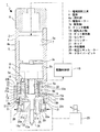
電動回転工具1は本体2と空圧ユニット3を備えている(図1参照)。
The
本体2は筐体4に所要の各部が配置されて成る。筐体4は上下に延びる略筒状に形成されたケース5とケース5の上端部に取り付けられたキャップ6とから成る。筐体4の外周面は電動回転工具1の使用時に作業者に把持される把持部4aとされている。
The
ケース5の内部には上下に位置するモーター配置空間5aと機構配置空間5bが形成され、モーター配置空間5aと機構配置空間5bは連通されている。ケース5の内部における下端部の中央部には上下に延びる軸挿通孔5cが形成され、軸挿通孔5cは上端が機構配置空間5bに連通されている。
Inside the case 5, a
ケース5の内部には軸挿通孔5cの外周側に環状の部材配置空間5dが形成され、部材配置空間5dは下方に開口されている。部材配置空間5dは一部がその上方に位置する機構配置空間5bに連通部5eを介して連通されている。
In the case 5, an annular
ケース5のモーター配置空間5aには電動モーター7が配置され、電動モーター7は駆動軸7aが下方へ突出された状態で設けられている。
An
ケース5の機構配置空間5bには減速機構8とクラッチ機構9が上下に位置された状態で配置されている。減速機構8は電動モーター7の回転速度を減じて後述する回転出力軸に伝達する機能を有している。
In the mechanism arrangement space 5b of the case 5, the
クラッチ機構9の下面には突部9aが設けられ、突部9aに隣接する部分が凹部9bとして形成されている(図2参照)。
A
ケース5の軸挿通孔5cには回転出力軸10の一部が配置され、回転出力軸10は電動モーター7の駆動軸7aに減速機構8を介して連結される(図1参照)。従って、電動モーター7が回転されると、その駆動力が減速機構8を介して回転出力軸10に伝達され、回転出力軸10が減速機構8によって減速されて回転される。
A part of the
回転出力軸10は上下方向における中央部に設けられた被検出部11と被検出部11の上側に位置する駆動力伝達部12と被検出部11の下側に位置するビット着脱部13とから成る。ビット着脱部13には下方に開口されたビット嵌合穴13aが形成され、ビット嵌合穴13aは水平断面形状が非円形状、例えば、六角形状等に形成されている。
The
ケース5の連通部5eには鋼球14が配置されている。鋼球14は上端部がクラッチ機構9の下面に形成された突部9aと凹部9bの両方に係合された状態とされている(図2参照)。
A
ケース5の下端部には回転出力軸10を挟んだ反対側に一対のセンサー15、15が取り付けられ、センサー15、15は検出部15a、15aがケース5の下方に位置されている(図1参照)。
A pair of
センサー15、15の検出部15a、15aは回転出力軸10の被検出部11の側方に位置され、回転出力軸10が、例えば、上下方向へ移動されたときの被検出部11の変位を検出する。
The
電動回転工具1には駆動制御部16が設けられている。駆動制御部16は、例えば、ケース5の内部に配置され、電動モーター7に対して駆動制御信号を送出する。電動モーター7に駆動制御部16から送出された駆動制御信号が入力されると、電動モーター7が回転又は停止される。
The
駆動制御部16にはセンサー15、15によって検出された検出結果に基づく検出信号が入力される。駆動制御部16はセンサー15、15から入力された検出信号に基づいた駆動制御信号を電動モーター7に送出する。
A detection signal based on the detection result detected by the
空圧ユニット3はホルダー17に所要の各部が保持されて成る。ホルダー17は上方に開口された箱状に形成され、底面部18と底面部18の外周部から上方へ突出された周面部19とを有し、ケース5の下端部を下方から覆う状態で周面部19が筐体4に固定されている。
The
底面部18には中央部に軸挿通孔18aが形成され軸挿通孔18aを挟んだ反対側にロッド挿通孔18b、18bが形成されている。底面部18の軸挿通孔18aには回転出力軸10のビット着脱部13が挿通され、ビット着脱部13がホルダー17から下方へ突出されている。
底面部18の下面にはシリンダー20、20が取り付けられている。シリンダー20、20にはそれぞれ供給孔20a、20aが形成されている。シリンダー20、20としては、例えば、エアーシリンダーが用いられている。
A
シリンダー20、20にはそれぞれロッド21、21が上下方向へ移動可能に支持され、ロッド21、21はそれぞれ上下方向を向く板状の閉塞部21a、21aと閉塞部21a、21aの中央部から上方へ突出された軸部21b、21bとから成る。閉塞部21a、21aはそれぞれシリンダー20、20の内部に位置され、軸部21b、21bはそれぞれ底面部18のロッド挿通孔18b、18bに挿通されている。ロッド21、21は回転出力軸10の軸中心を基準として半径方向における同じ距離に位置されている。シリンダー20、20の内部はそれぞれ閉塞部21a、21aによって気密状態が保持されている。
ホルダー17の内部には押付部材22と受け部材23が配置されている。
A pressing
押付部材22は上下方向に延びる筒状に形成された押付部22aと押付部22aの下端部から外方へ張り出された被作用部22bとから成る。押付部22aは下端部を除きケース5の部材配置空間5dに配置されている。押付部材22は被作用部22bに下方からロッド21、21の軸部21b、21bが押し付けられている。押付部材22は被作用部22bの軸中心が回転出力軸10の軸中心に一致されている。
The pressing
受け部材23は上下方向に延びる筒状に形成された基体部23aと基体部23aの上端部から外方へ張り出された受部23bとから成る。受け部材23はケース5の部材配置空間5dに配置され、基体部23aが押付部材22の内側に位置され、受部23bに下方から押付部材22の押付部22aが押し付けられている。受け部材23の受部23bの上面の一部はケース5の連通部5eに配置された鋼球14が接した状態とされている。
The receiving
シリンダー20、20には供給孔20a、20aを介して電空レギュレーター25からエアーが供給される。電空レギュレーター25から供給されるエアーの供給量に応じてシリンダー20、20の内圧が変化され、シリンダー20、20の内圧の大きさに応じてそれぞれロッド21、21のクラッチ機構9に対する負荷が変化される。ロッド21、21の負荷が変化されるとロッド21、21による押付部材22に対する押圧力が変化され、変化された押圧力が受け部材23を介して鋼球14に伝達される。従って、電空レギュレーター25によって鋼球14のクラッチ機構9に対する押付力(負荷)が調整される。
Air is supplied to the
このようにシリンダー20、20、ロッド21、21、押付部材22、受け部材23及び鋼球14はクラッチ機構9に対して負荷を付与しクラッチ機構9による電動モーター7の駆動軸7aと回転出力軸10の連結状態を制御する予圧機構24として機能する。
As described above, the
電空レギュレーター25のシリンダー20、20に対するエアーの供給量は、電空レギュレーター25に対して図示しない外部制御機器から出力される入力電気信号により設定される。
The amount of air supplied to the
このように電動回転工具1にあっては、電空レギュレーター25からのシリンダー20、20に対するエアーの供給量を調整することにより、シリンダー20、20の内圧を変化させて鋼球14のクラッチ機構9に対する押付力を変化させることができる。クラッチ機構9は、後述するように、回転出力軸10に予め定められたトルクより大きな負荷が付与されたときに回転されて電動モーター7の駆動軸7aと回転出力軸10の連結を解除するように機能する。従って、電空レギュレーター25からのシリンダー20、20に対するエアーの供給量が調整されたときに、シリンダー20、20の内圧が大きくされることにより電動回転工具1におけるトルクが大きくなり、逆に、シリンダー20、20の内圧が小さくされることにより電動回転工具1におけるトルクが小さくなる。
As described above, in the
電空レギュレーター25からのシリンダー20、20に対するエアーの供給量は電空レギュレーター25に対する入力電気信号により設定されため、電空レギュレーター25に対する入力電気信号により電動回転工具1におけるトルクの大きさを設定することができることになる。
Since the supply amount of air from the
[電動回転工具の動作]
次に、電動回転工具1の動作について説明する。
[Operation of electric rotating tool]
Next, the operation of the
電動回転工具1によってネジ締めが行われるときには、回転出力軸10のビット挿脱部13に形成されたビット嵌合穴13aにドライバービット26が嵌合されて装着される。
When the
電動モーター7が回転されると、電動モーター7の駆動力が減速機構8を介して回転出力軸10に伝達され、回転出力軸10とドライバービット26が一体になって減速されて回転されネジ締め作業が行われる。
When the
ネジ締め作業においては、回転出力軸10に対する負荷が付与されクラッチ機構9に回転力が作用するが、回転出力軸10に対する負荷の大きさが電動回転工具1におけるトルクの大きさより小さい状態においては、鋼球14によってクラッチ機構9の回転が規制され(図2参照)、電動モーター7の駆動軸7aと回転出力軸10の連結状態が保持され回転出力軸10とドライバービット26の回転状態が保持される。
In the screw tightening operation, a load is applied to the
ネジ締め作業において、電動回転工具1において予め設定されたトルクより回転出力軸10に対する負荷が大きくなると、ドライバービット26と回転出力軸10の回転が停止される。回転出力軸10の回転が停止されると、クラッチ機構9が所定の方向へ回転される。クラッチ機構9が所定の方向へ回転されると、クラッチ機構9の突部9aが鋼球14を乗り上げて鋼球14が突部9aにのみ係合される(図3参照)。
In the screw tightening operation, when the load on the
鋼球14が突部9aにのみ係合されると、電動モーター7の駆動軸7aと回転出力軸10の連結が解除される。このとき回転出力軸10が軸方向へ変位され、センサー15、15によって被検出部11の上下方向における変位が検出され、検出結果が駆動制御部16に送出される。センサー15、15の検出結果が駆動制御部16に入力されると、駆動制御部16から電動モーター7に対して回転停止の制御信号が送出されて電動モーター7の回転が停止される。
When the
尚、上記には、センサー15、15によって被検出部11の上下方向における変位が検出される例を示したが、例えば、センサー15、15によって回転出力軸10の回転状態が検出され、検出結果が駆動制御部16に送出されるようにしてもよい。
In addition, although the example which detects the displacement in the up-down direction of the to-
[まとめ]
以上に記載した通り、電動回転工具1にはクラッチ機構9に対して負荷を付与しクラッチ機構9による電動モーター7の駆動軸7aと回転出力軸10の連結状態を制御する予圧機構24を備え、予圧機構24にシリンダー20、20とシリンダー20、20に対して動作してクラッチ機構9に対する負荷の大きさを変化させるロッド21、21とを設けている。
[Summary]
As described above, the
従って、シリンダー20、20の内圧に応じてクラッチ機構9に対する予圧機構24の負荷が変化されるため、製造コストの高騰を来たすことなく電動回転工具1のトルクの制御を外部から容易かつ適正に行うことができ、使い勝手の向上を図ることができる。
Therefore, since the load of the
また、電動回転工具1においては、シリンダー20、20としてエアーシリンダーが用いられ、シリンダー20、20の内圧を電空レギュレーター25によって調整しエアーシリンダー20、20の内圧の変化に応じてロッド21、21のクラッチ機構9に対する負荷が変化されるようにしている。
In the
従って、電動回転工具1のトルクを外部からの電空レギュレーター25に対する入力電気信号によって調整することができ、トルクの制御を容易に設定することができる。
Therefore, the torque of the
尚、電動回転工具1のトルクの範囲はシリンダー20、20の最低作動圧力からシリンダー20、20の最大耐用圧力の範囲で定まるため、使用する電空レギュレーター25の種類によっては電動回転工具1のトルクの値を大きくすることが可能である。
The torque range of the
また、電動回転工具1には複数のシリンダー20、20とロッド21、21が設けられているため、各シリンダー20、20の内圧を各別に調整することにより、電動回転工具1のトルクの微調整を行うことができる。
Further, since the
尚、上記には、二つのシリンダー20、20とロッド21、21を設けた例を示したが、電動回転工具1には一つ又は三つ以上の任意の数のシリンダー20とロッド21を設けることが可能である。
In addition, although the example which provided the two
さらに、シリンダー20、20とロッド21、21が回転出力軸10を挟んだ反対側に設けられているため、予圧機構24によるクラッチ機構9に対する負荷を良好なバランスで付与することができ、クラッチ機構9の適正な動作性能を確保することができる。
Further, since the
さらにまた、電動回転工具1にあっては、クラッチ機構9によって電動モーター7の駆動軸7aと回転出力軸10の連結が解除されたときにセンサー15、15による検出結果に基づいて電動モーター7の回転が停止される。
Furthermore, in the
従って、回転出力軸10とドライバービット26の回転の停止状態を確実に保持することができると共に消費電力の低減を図ることができる。
Therefore, the rotation stop state of the
[その他]
上記には、空圧レギュレーター25によってシリンダー20、20の内圧を調整する例を示したが、電動回転工具1においては、例えば、ロッドが油圧によってシリンダーに対して動作するように構成することも可能である。
[Others]
Although the example which adjusts the internal pressure of the
また、空圧レギュレーター25に代えて手動によってバルブを開閉しシリンダー20、20の内圧を調整する構成にすることも可能である。
In addition, instead of the
[本技術]
本技術は、以下のような構成とすることができる。
[Technology]
The present technology may be configured as follows.
(1)把持部を有する筐体と、前記筐体の内部に配置された電動モーターと、前記筐体の内部に配置されたクラッチ機構と、ドライバービットが着脱されるビット着脱部を有し前記電動モーターの駆動軸に連結可能とされ前記電動モーターの駆動力によって回転される回転出力軸と、前記クラッチ機構に対して負荷を付与し前記クラッチ機構による前記駆動軸と前記回転出力軸の連結状態を制御する予圧機構とを備え、前記予圧機構にシリンダーと前記シリンダーに対して動作されて前記クラッチ機構に対する負荷の大きさを変化させるロッドとを設けた電動回転工具。 (1) A housing having a gripping portion, an electric motor disposed inside the housing, a clutch mechanism disposed inside the housing, and a bit attaching / detaching portion to / from which a driver bit is attached / detached A rotation output shaft that is connectable to a drive shaft of the electric motor and rotated by a driving force of the electric motor, and a connection state of the drive shaft and the rotation output shaft by the clutch mechanism by applying a load to the clutch mechanism An electric rotary tool provided with a preload mechanism for controlling the cylinder, and provided with a cylinder and a rod that is operated with respect to the cylinder and changes a magnitude of a load on the clutch mechanism.
(2)前記シリンダーとしてエアーシリンダーが用いられ、前記エアーシリンダーの内圧を電空レギュレーターによって調整し前記エアーシリンダーの内圧の変化に応じて前記ロッドの前記クラッチ機構に対する負荷が変化されるようにした前記(1)に記載の電動回転工具。 (2) An air cylinder is used as the cylinder, and an internal pressure of the air cylinder is adjusted by an electropneumatic regulator so that a load on the clutch mechanism of the rod is changed according to a change in the internal pressure of the air cylinder. The electric rotary tool according to (1).
(3)前記シリンダーと前記ロッドが複数設けられた前記(1)又は前記(2)に記載の電動回転工具。 (3) The electric rotary tool according to (1) or (2), wherein a plurality of the cylinders and the rods are provided.
(4)前記シリンダーと前記ロッドが前記回転出力軸を挟んだ反対側に設けられた前記(3)に記載の電動回転工具。 (4) The electric rotary tool according to (3), wherein the cylinder and the rod are provided on opposite sides of the rotation output shaft.
(5)前記回転出力軸の状態を検出するセンサーを設け、前記クラッチ機構によって前記駆動軸と前記回転出力軸の連結が解除されたときに前記センサーによる検出結果に基づいて前記電動モーターの回転が停止されるようにした前記(1)から前記(4)の何れかに記載の電動回転工具。 (5) A sensor for detecting a state of the rotation output shaft is provided, and the electric motor rotates based on a detection result of the sensor when the connection between the drive shaft and the rotation output shaft is released by the clutch mechanism. The electric rotary tool according to any one of (1) to (4), wherein the electric rotary tool is stopped.
上記した技術の最良の形態において示した各部の具体的な形状及び構造は、何れも本技術を実施する際の具体化のほんの一例を示したものにすぎず、これらによって本技術の技術的範囲が限定的に解釈されることがあってはならないものである。 The specific shapes and structures of the respective parts shown in the best mode of the technology described above are merely examples of the implementation of the present technology, and thus the technical scope of the present technology. Should not be interpreted in a limited way.
1…電動回転工具、4…筐体、4a…把持部、7…電動モーター、7a…駆動軸、9…クラッチ機構、10…回転出力軸、13…ビット着脱部、15…センサー、20…シリンダー、21…ロッド、24…予圧機構、25…電空レギュレーター、26…ドライバービット
DESCRIPTION OF
Claims (5)
前記筐体の内部に配置された電動モーターと、
前記筐体の内部に配置されたクラッチ機構と、
ドライバービットが着脱されるビット着脱部を有し前記電動モーターの駆動軸に連結可能とされ前記電動モーターの駆動力によって回転される回転出力軸と、
前記クラッチ機構に対して負荷を付与し前記クラッチ機構による前記駆動軸と前記回転出力軸の連結状態を制御する予圧機構とを備え、
前記予圧機構にシリンダーと前記シリンダーに対して動作されて前記クラッチ機構に対する負荷の大きさを変化させるロッドとを設けた
電動回転工具。 A housing having a gripping portion;
An electric motor disposed inside the housing;
A clutch mechanism disposed inside the housing;
A rotating output shaft that has a bit attaching / detaching portion to / from which the driver bit is attached and can be connected to the driving shaft of the electric motor and is rotated by the driving force of the electric motor;
A preload mechanism that applies a load to the clutch mechanism and controls a connection state of the drive shaft and the rotation output shaft by the clutch mechanism;
An electric rotary tool, wherein the preload mechanism is provided with a cylinder and a rod that is operated with respect to the cylinder and changes a magnitude of a load on the clutch mechanism.
前記エアーシリンダーの内圧を電空レギュレーターによって調整し前記エアーシリンダーの内圧の変化に応じて前記ロッドの前記クラッチ機構に対する負荷が変化されるようにした
請求項1に記載の電動回転工具。 An air cylinder is used as the cylinder,
The electric rotary tool according to claim 1, wherein an internal pressure of the air cylinder is adjusted by an electropneumatic regulator so that a load on the clutch mechanism of the rod is changed according to a change in the internal pressure of the air cylinder.
請求項1に記載の電動回転工具。 The electric rotary tool according to claim 1, wherein a plurality of the cylinders and the rods are provided.
請求項3に記載の電動回転工具。 The electric rotary tool according to claim 3, wherein the cylinder and the rod are provided on opposite sides of the rotary output shaft.
前記クラッチ機構によって前記駆動軸と前記回転出力軸の連結が解除されたときに前記センサーによる検出結果に基づいて前記電動モーターの回転が停止されるようにした
請求項1に記載の電動回転工具。 A sensor for detecting the state of the rotation output shaft is provided,
The electric rotary tool according to claim 1, wherein rotation of the electric motor is stopped based on a detection result by the sensor when the connection between the drive shaft and the rotation output shaft is released by the clutch mechanism.
Priority Applications (1)
| Application Number | Priority Date | Filing Date | Title |
|---|---|---|---|
| JP2011275575A JP2013123789A (en) | 2011-12-16 | 2011-12-16 | Electric rotary tool |
Applications Claiming Priority (1)
| Application Number | Priority Date | Filing Date | Title |
|---|---|---|---|
| JP2011275575A JP2013123789A (en) | 2011-12-16 | 2011-12-16 | Electric rotary tool |
Publications (1)
| Publication Number | Publication Date |
|---|---|
| JP2013123789A true JP2013123789A (en) | 2013-06-24 |
Family
ID=48775360
Family Applications (1)
| Application Number | Title | Priority Date | Filing Date |
|---|---|---|---|
| JP2011275575A Pending JP2013123789A (en) | 2011-12-16 | 2011-12-16 | Electric rotary tool |
Country Status (1)
| Country | Link |
|---|---|
| JP (1) | JP2013123789A (en) |
-
2011
- 2011-12-16 JP JP2011275575A patent/JP2013123789A/en active Pending
Similar Documents
| Publication | Publication Date | Title |
|---|---|---|
| JP4304631B2 (en) | Chuck device | |
| US9050660B2 (en) | Drill | |
| US9878427B2 (en) | Hand-held power tool, in particular battery-powered screwdriver | |
| JP4533928B2 (en) | Electric actuator | |
| WO2013031652A1 (en) | Clamping device | |
| KR20170004361U (en) | Precision Torque Screwdriver | |
| EP2759377B1 (en) | Power tool with spindle lock | |
| US20130192858A1 (en) | Transportable screwing tool with integrated switching element | |
| JP7118343B2 (en) | socket | |
| KR20140002562A (en) | Clamping chuck | |
| JP2007032611A (en) | Torque adjusting bolt | |
| JP6499063B2 (en) | Workpiece gripping device | |
| JP2013123789A (en) | Electric rotary tool | |
| US7520128B1 (en) | Method for automatically cycling a torque wrench | |
| DK3208048T3 (en) | TOOL | |
| CN101444907A (en) | Combination tool | |
| US11389970B2 (en) | Tool adapter for manipulating commercial tools with a robot hand | |
| KR20140109688A (en) | Multi-link finger module of robot hand | |
| KR101746093B1 (en) | adaptor for tools and drilling apparatus using the same | |
| KR20120131758A (en) | Separation type positioner of air operated valve system | |
| US20220111501A1 (en) | Power Tool with Adaptive Speed During Tightening Cycle | |
| JP6550679B2 (en) | Shock absorber for screw tightening device | |
| JP6418083B2 (en) | Tightening machine | |
| US10137554B2 (en) | Hand-held belt sander | |
| CN204800594U (en) | Power tool |