JP2013123733A - Controller and control method for pinch roll gap - Google Patents
Controller and control method for pinch roll gap Download PDFInfo
- Publication number
- JP2013123733A JP2013123733A JP2011273590A JP2011273590A JP2013123733A JP 2013123733 A JP2013123733 A JP 2013123733A JP 2011273590 A JP2011273590 A JP 2011273590A JP 2011273590 A JP2011273590 A JP 2011273590A JP 2013123733 A JP2013123733 A JP 2013123733A
- Authority
- JP
- Japan
- Prior art keywords
- gap
- pinch roll
- tail end
- steel strip
- pinch
- Prior art date
- Legal status (The legal status is an assumption and is not a legal conclusion. Google has not performed a legal analysis and makes no representation as to the accuracy of the status listed.)
- Pending
Links
Images
Abstract
Description
本発明は、例えば、熱間圧延ライン等の圧延ラインにおいて、コイラー(巻取り装置)の上流側に配置されて鋼帯を厚さ方向で挟持する一対のピンチロールのギャップを制御し、コイラーで巻き取られた鋼帯からなるコイルの巻き形状の乱れを抑制するための制御装置及び制御方法に関する。 The present invention controls a gap between a pair of pinch rolls arranged on the upstream side of a coiler (winding device) and sandwiching a steel strip in the thickness direction in a rolling line such as a hot rolling line. The present invention relates to a control device and a control method for suppressing disturbance of a winding shape of a coil made of a wound steel strip.
製鉄所等において、熱間圧延ライン等の圧延ラインでは、鋼帯を厚さ方向で挟持する一対のピンチロールのギャップを目標の板厚に対して一定値に設定した状態で、コイラーにより鋼帯を最後まで巻き取る場合が多い。ここで、一対のピンチロールは、鋼帯を圧延する仕上圧延機と、鋼帯をコイル状に巻き取るコイラーとの間に配置されている。
そして、コイラーに巻き取られた鋼帯に対し、その巻き形状の乱れを抑制するための技術としては、例えば、特許文献1に開示されている技術がある。
特許文献1に開示されている技術は、鋼帯の尾端が仕上圧延機から抜けた(圧延が終了した)後、ピンチロールを回転させる電動機の回転速度を、コイラーにより巻き取られつつある鋼帯の搬送速度よりも遅い速度に速度制御するとともに、電動機の電流の実績値に基づいて、ピンチロールのギャップを制御する技術である。
In a steel mill, etc., in a rolling line such as a hot rolling line, a steel strip is used by a coiler in a state where a gap between a pair of pinch rolls sandwiching the steel strip in the thickness direction is set to a constant value with respect to a target plate thickness. Is often wound up to the end. Here, the pair of pinch rolls are arranged between a finish rolling mill that rolls the steel strip and a coiler that winds the steel strip into a coil shape.
And as a technique for suppressing disturbance of the winding shape with respect to the steel strip wound up by the coiler, there exists a technique currently disclosed by patent document 1, for example.
The technology disclosed in Patent Document 1 is a steel in which the rotational speed of an electric motor that rotates a pinch roll is wound by a coiler after the tail end of the steel strip has been removed from the finishing mill (rolling is completed). In this technique, the speed of the belt is controlled at a speed lower than the belt conveyance speed, and the gap of the pinch roll is controlled based on the actual value of the current of the electric motor.
上記のような巻き形状の乱れは、鋼帯が仕上圧延機を抜けた際に、ピンチロールのギャップが適切な値となっておらず、適切な後方張力(バックテンション)を鋼帯に付与することができないために、鋼帯が幅方向(左右方向)に振られて蛇行することにより発生する。
巻き形状に乱れが発生すると、コイル状に巻き取られた鋼帯(以下、「コイル」と記載する場合がある)の搬送方法がアップエンド搬送である場合や、コイル搬送時等のクレーンにおけるハンドリング時等において、巻きが乱れてコイルの側面から飛び出した部分に、耳折れ(鋼帯の折れ)や耳切れ(鋼帯の切れ)が発生することとなる。このような耳折れや耳切れの発生は、特に、鋼帯が薄物(板厚が薄い鋼帯)である場合に顕著となる。
このため、鋼帯のうち、巻き形状が乱れた部分だけでなく、鋼帯が仕上圧延機を抜けた時点で仕上圧延機とコイラーとの間に存在する部分(例えば、約100[m]前後の健全な部分)も、製品として不合格の品質となり、歩留りが低下するという問題が発生するおそれがある。
When the steel strip passes through the finish rolling mill, the winding shape disorder as described above gives an appropriate rear tension (back tension) to the steel strip because the pinch roll gap is not an appropriate value. This is caused by the meandering of the steel strip being swung in the width direction (left-right direction).
When the winding shape is disturbed, handling of the steel strip wound in a coil shape (hereinafter sometimes referred to as “coil”) is up-end conveyance or handling in a crane during coil conveyance. In some cases, ear breaks (breaking of the steel strip) and ear cuts (cutting of the steel strip) occur at the portions where the winding is disturbed and protrude from the side surface of the coil. The occurrence of such ear breaks and ear breaks is particularly noticeable when the steel strip is thin (a steel strip having a thin plate thickness).
For this reason, not only the portion where the winding shape is disturbed in the steel strip, but also the portion existing between the finish rolling mill and the coiler (for example, about 100 [m] or so) when the steel strip exits the finishing mill. The sound part of the product may also be rejected as a product, and the yield may be reduced.
また、耳折れや耳切れが発生すると、コイルのうち、巻きが乱れた部分を切り捨てるための工程として余分な工程が発生するため、製造効率が低下するという問題が発生するおそれがある。
しかしながら、上述した特許文献1に開示されている技術を含め、従来の技術には、鋼帯が仕上圧延機を抜けた際に、ピンチロールのギャップを適切な値に制御して、適切な後方張力を鋼帯に付与することにより、コイルの巻き形状の乱れを抑制するための技術は提案されていない。
本発明は、上記のような問題点に着目してなされたもので、鋼帯が仕上圧延機を抜けた際のピンチロールのギャップを制御して、コイルの巻き形状の乱れを抑制することが可能な、ピンチロールギャップの制御装置及び制御方法を提供することを課題とする。
Further, when the ear break or the ear break occurs, an extra step is generated as a step for discarding the portion of the coil whose winding is disturbed, which may cause a problem that the manufacturing efficiency is lowered.
However, in the conventional techniques including the technique disclosed in Patent Document 1 described above, when the steel strip passes through the finish rolling mill, the pinch roll gap is controlled to an appropriate value, and the appropriate rear A technique for suppressing disturbance of the coiled shape of the coil by applying tension to the steel strip has not been proposed.
The present invention has been made paying attention to the problems as described above, and controls the gap of the pinch roll when the steel strip passes through the finish rolling mill, thereby suppressing disturbance of the coil winding shape. It is an object of the present invention to provide a pinch roll gap control device and control method that are possible.
上記課題を解決するために、本発明のうち、請求項1に記載した発明は、搬送されてくる鋼帯を圧延する仕上圧延機とコイラーとの間に配置され、且つ前記コイラーに巻き取られる前の鋼帯を挟持する一対のピンチロールのギャップを制御するピンチロールギャップの制御装置であって、
前記一対のピンチロールのギャップを変化させるロールギャップ変化機構と、
前記ロールギャップ変化機構による前記ギャップの変化度合いを制御する変化度合制御部と、
前記仕上圧延機と前記ピンチロールとの間で前記鋼帯の板厚を検出する圧延後板厚検出部と、
前記圧延及び巻き取りが完了した鋼帯における尾端から予め設定した長さまでの尾端側部分のうち前記コイラーで巻き取られたコイルの側面からの突出量が予め設定した突出量閾値未満である部分の少なくとも一部を前記圧延後板厚検出部で検出した合格部分板厚と、前記突出量が前記突出量閾値未満である前記尾端側部分を挟持した前記一対のピンチロールのギャップである合格部分挟持ギャップと、を対応させたデータテーブルであるギャップ制御テーブルを予め記憶するギャップ制御テーブル記憶部と、を備え、
前記変化度合制御部は、前記尾端側部分を挟持する前記一対のピンチロールのギャップが、前記仕上圧延機が前記尾端側部分を圧延している状態で前記圧延後板厚検出部が検出した尾端側部分の板厚と等しい前記合格部分板厚に対応した前記合格部分挟持ギャップとなるように、前記変化度合いを制御することを特徴とするものである。
In order to solve the above-mentioned problems, the invention described in claim 1 of the present invention is arranged between a finish rolling mill for rolling a steel strip being conveyed and a coiler, and is wound around the coiler. A control device for a pinch roll gap that controls a gap between a pair of pinch rolls that sandwich the previous steel strip,
A roll gap changing mechanism for changing a gap between the pair of pinch rolls;
A degree-of-change control unit that controls the degree of change of the gap by the roll gap change mechanism;
A post-rolling plate thickness detection unit that detects a plate thickness of the steel strip between the finish rolling mill and the pinch roll,
The protrusion amount from the side surface of the coil wound by the coiler in the tail end side portion from the tail end to the preset length in the steel strip that has been rolled and wound is less than a preset protrusion amount threshold value. An acceptable partial plate thickness in which at least a part of the portion is detected by the post-rolling plate thickness detection unit, and a gap between the pair of pinch rolls sandwiching the tail end side portion in which the protruding amount is less than the protruding amount threshold A gap control table storage unit that stores in advance a gap control table, which is a data table corresponding to the accepted part clamping gap,
The change degree control unit detects the gap between the pair of pinch rolls sandwiching the tail end side portion, and the post-rolling sheet thickness detection unit detects that the finishing mill is rolling the tail end side portion. The degree of change is controlled so that the accepted portion clamping gap corresponding to the accepted partial plate thickness equal to the plate thickness of the tail end side portion.
本発明によると、変化度合制御部が、尾端側部分を挟持する一対のピンチロールのギャップが、仕上圧延機が尾端側部分を圧延している状態で圧延後板厚検出部が検出した尾端側部分の板厚と等しい合格部分板厚に対応した合格部分挟持ギャップとなるように、一対のピンチロールのギャップの変化度合いを制御する。
このため、尾端側部分が仕上圧延機から抜けた際の、一対のピンチロールのギャップを、尾端側部分の突出量が予め設定した突出量閾値未満である場合の、合格部分板厚に応じたギャップに制御することが可能となる。
According to the present invention, the degree-of-change control unit detects the gap between the pair of pinch rolls that sandwich the tail end side portion, and the post-rolling sheet thickness detection unit detects that the finishing mill is rolling the tail end side portion. The degree of change in the gap between the pair of pinch rolls is controlled so as to obtain an acceptable portion clamping gap corresponding to an acceptable partial plate thickness equal to the plate thickness of the tail end side portion.
For this reason, the gap between the pair of pinch rolls when the tail end side part has come out of the finish rolling mill, to the accepted part thickness when the protrusion amount of the tail end side part is less than a preset protrusion amount threshold value. It is possible to control the gap according to the response.
次に、本発明のうち、請求項2に記載した発明は、請求項1に従属する発明であって、前記ピンチロールを回転させるピンチロール回転部がピンチロールの回転速度を前記鋼帯の搬送速度よりも減速させた状態で、前記ピンチロール回転部に発生する抵抗電流値を検出する抵抗電流値検出部と、
前記突出量が前記突出量閾値未満である前記尾端側部分を前記一対のピンチロールが挟持している状態で前記抵抗電流値検出部が検出した抵抗電流値に基づいて前記ギャップを検出するギャップ検出部と、を備えることを特徴とするものである。
Next, among the present inventions, the invention described in claim 2 is an invention dependent on claim 1, wherein the pinch roll rotating part for rotating the pinch roll controls the rotation speed of the pinch roll to convey the steel strip. A resistance current value detection unit that detects a resistance current value generated in the pinch roll rotating unit in a state of being decelerated from the speed;
A gap for detecting the gap based on a resistance current value detected by the resistance current value detection unit in a state where the pair of pinch rolls holds the tail end side portion where the protrusion amount is less than the protrusion amount threshold. And a detector.
本発明によると、ギャップ検出部が、尾端側部分のうちコイラーで巻き取られたコイルの側面からの突出量が予め設定した突出量閾値未満である部分を一対のピンチロールが挟持している状態で、抵抗電流値検出部が検出した抵抗電流値に基づいて、一対のピンチロールのギャップを検出する。
このため、継続的な使用等によりピンチロールの磨耗が進行した場合であっても、磨耗の進行度合いに応じて変化する抵抗電流値に基づいて、一対のピンチロールのギャップを検出することが可能となる。
According to the present invention, the pair of pinch rolls sandwich the portion of the gap detection portion where the protrusion amount from the side surface of the coil wound by the coiler is less than a preset protrusion amount threshold value in the tail end side portion. In the state, the gap between the pair of pinch rolls is detected based on the resistance current value detected by the resistance current value detection unit.
For this reason, even when the wear of the pinch roll has progressed due to continuous use, etc., it is possible to detect the gap between the pair of pinch rolls based on the resistance current value that changes according to the progress of the wear. It becomes.
次に、本発明のうち、請求項3に記載した発明は、請求項2に従属する発明であって、前記抵抗電流値検出部は、前記ピンチロール回転部が前記ピンチロールの回転速度を前記鋼帯の搬送速度に対して20%以上35%以下の範囲内で減速させた状態で前記抵抗電流値を検出することを特徴とするものである。
本発明によると、抵抗電流値検出部が、ピンチロール回転部がピンチロールの回転速度を鋼帯の搬送速度に対して20%以上35%以下の範囲内で減速させた状態で、抵抗電流値を検出する。
Next, among the present inventions, the invention described in claim 3 is an invention dependent on claim 2, wherein the resistance current value detection unit is configured such that the pinch roll rotation unit determines the rotation speed of the pinch roll. The resistance current value is detected in a state in which the steel strip is decelerated within a range of 20% to 35% with respect to the conveyance speed of the steel strip.
According to the present invention, the resistance current value detection unit is configured so that the pinch roll rotating unit decelerates the rotation speed of the pinch roll within a range of 20% to 35% with respect to the conveying speed of the steel strip. Is detected.
このため、ピンチロールの回転速度を鋼帯の搬送速度に対して20%未満で減速させた状態で抵抗電流値を検出する場合と比較して、抵抗電流値の検出精度を安定させることが可能となる。これに加え、ピンチロールの回転速度を鋼帯の搬送速度に対して35%を超えて減速させた状態で抵抗電流値を検出する場合と比較して、一対のピンチロールで挟持された鋼帯に擦り傷等の欠陥が発生する可能性や、コイル全体に対して、巻き形状の乱れが発生する可能性を低減させることが可能となる。 For this reason, it is possible to stabilize the detection accuracy of the resistance current value as compared with the case where the resistance current value is detected in a state where the rotation speed of the pinch roll is decelerated by less than 20% with respect to the conveying speed of the steel strip. It becomes. In addition to this, compared with the case where the resistance current value is detected in a state where the rotational speed of the pinch roll is reduced by more than 35% with respect to the conveying speed of the steel band, the steel band sandwiched between the pair of pinch rolls. Thus, it is possible to reduce the possibility of occurrence of defects such as scratches and the possibility of occurrence of winding disorder on the entire coil.
次に、本発明のうち、請求項4に記載した発明は、搬送されてくる鋼帯を圧延する仕上圧延機とコイラーとの間に配置され、且つ前記コイラーに巻き取られる前の鋼帯を挟持する一対のピンチロールのギャップを制御するピンチロールギャップの制御方法であって、
前記圧延及び巻き取りが完了した鋼帯における尾端から予め設定した長さまでの尾端側部分のうち前記コイラーで巻き取られたコイルの側面からの突出量が予め設定した突出量閾値未満である部分の少なくとも一部の板厚を前記仕上圧延機と前記ピンチロールとの間で検出した合格部分板厚と、前記突出量が前記突出量閾値未満である前記尾端側部分を挟持した前記一対のピンチロールのギャップである合格部分挟持ギャップと、を対応させたデータテーブルであるギャップ制御テーブルを予め記憶するギャップ制御テーブル記憶ステップと、
前記仕上圧延機と前記ピンチロールとの間で前記鋼帯の板厚を検出する圧延後板厚検出ステップと、
前記尾端側部分を挟持する前記一対のピンチロールのギャップが、前記仕上圧延機が前記尾端側部分を圧延している状態で前記圧延後板厚検出ステップにおいて検出した尾端側部分の板厚と等しい前記合格部分板厚に対応した前記合格部分挟持ギャップとなるように、前記ギャップの変化度合いを制御する変化度合制御ステップと、を有することを特徴とするものである。
Next, among the present inventions, the invention described in claim 4 is a steel strip that is disposed between a finish rolling mill that rolls a steel strip being conveyed and a coiler, and before being wound around the coiler. A pinch roll gap control method for controlling a gap between a pair of pinch rolls to be sandwiched,
The protrusion amount from the side surface of the coil wound by the coiler in the tail end side portion from the tail end to the preset length in the steel strip that has been rolled and wound is less than a preset protrusion amount threshold value. The pair of parts sandwiching the tail end side part in which the plate thickness is detected between the finish rolling mill and the pinch roll and the protruding amount is less than the protruding amount threshold. A gap control table storage step for storing in advance a gap control table, which is a data table corresponding to the accepted part clamping gap which is the gap of the pinch roll of
A post-rolling thickness detection step for detecting the thickness of the steel strip between the finish rolling mill and the pinch roll;
The gap between the pair of pinch rolls sandwiching the tail end side portion is detected in the post-rolling plate thickness detection step in the state where the finishing mill is rolling the tail end side portion. And a change degree control step for controlling the degree of change of the gap so as to be the pass part clamping gap corresponding to the pass part plate thickness equal to the thickness.
本発明によると、変化度合制御ステップにおいて、尾端側部分を挟持する一対のピンチロールのギャップが、仕上圧延機が尾端側部分を圧延している状態で圧延後板厚検出ステップにおいて検出した尾端側部分の板厚と等しい合格部分板厚に対応した合格部分挟持ギャップとなるように、一対のピンチロールのギャップの変化度合いを制御する。
このため、尾端側部分が仕上圧延機から抜けた際の、一対のピンチロールのギャップを、尾端側部分の突出量が予め設定した突出量閾値未満である場合の、合格部分板厚に応じたギャップに制御することが可能となる。
According to the present invention, in the change degree control step, the gap between the pair of pinch rolls that sandwich the tail end portion is detected in the post-rolling thickness detection step in a state where the finishing mill is rolling the tail end portion. The degree of change in the gap between the pair of pinch rolls is controlled so as to obtain an acceptable portion clamping gap corresponding to an acceptable partial plate thickness equal to the plate thickness of the tail end side portion.
For this reason, the gap between the pair of pinch rolls when the tail end side part has come out of the finish rolling mill, to the accepted part thickness when the protrusion amount of the tail end side part is less than a preset protrusion amount threshold value. It is possible to control the gap according to the response.
次に、本発明のうち、請求項5に記載した発明は、請求項4に従属する発明であって、前記ピンチロールを回転させるピンチロール回転部がピンチロールの回転速度を前記鋼帯の搬送速度よりも減速させた状態で、前記ピンチロール回転部に発生する抵抗電流値を検出する抵抗電流値検出ステップと、
前記突出量が前記突出量閾値未満である前記尾端側部分を前記一対のピンチロールが挟持している状態で前記抵抗電流値検出ステップにおいて検出した抵抗電流値に基づいて、前記ギャップを検出するギャップ検出ステップと、を有することを特徴とするものである。
Next, among the present inventions, the invention described in claim 5 is an invention dependent on claim 4, wherein the pinch roll rotating part for rotating the pinch roll controls the rotation speed of the pinch roll to convey the steel strip. A resistance current value detecting step for detecting a resistance current value generated in the pinch roll rotating portion in a state where the speed is decelerated from the speed;
The gap is detected based on the resistance current value detected in the resistance current value detection step in a state where the pair of pinch rolls holds the tail end side portion where the protrusion amount is less than the protrusion amount threshold. And a gap detection step.
本発明によると、ギャップ検出ステップにおいて、尾端側部分のうちコイラーで巻き取られたコイルの側面からの突出量が予め設定した突出量閾値未満である部分を一対のピンチロールが挟持している状態で、抵抗電流値検出ステップにおいて検出した抵抗電流値に基づいて、一対のピンチロールのギャップを検出する。
このため、継続的な使用等によりピンチロールの磨耗が進行した場合であっても、磨耗の進行度合いに応じて変化する抵抗電流値に基づいて、一対のピンチロールのギャップを検出することが可能となる。
According to the present invention, in the gap detection step, the pair of pinch rolls holds a portion of the tail end portion where the protrusion amount from the side surface of the coil wound by the coiler is less than a preset protrusion amount threshold value. In the state, the gap between the pair of pinch rolls is detected based on the resistance current value detected in the resistance current value detection step.
For this reason, even when the wear of the pinch roll has progressed due to continuous use, etc., it is possible to detect the gap between the pair of pinch rolls based on the resistance current value that changes according to the progress of the wear. It becomes.
次に、本発明のうち、請求項6に記載した発明は、請求項5に従属する発明であって、前記抵抗電流値検出ステップでは、前記ピンチロール回転部が前記ピンチロールの回転速度を前記鋼帯の搬送速度に対して20%以上35%以下の範囲内で減速させた状態で前記抵抗電流値を検出することを特徴とするものである。
本発明によると、抵抗電流値検出ステップにおいて、ピンチロール回転部がピンチロールの回転速度を鋼帯の搬送速度に対して20%以上35%以下の範囲内で減速させた状態で、抵抗電流値を検出する。
Next, among the present inventions, the invention described in
According to the present invention, in the resistance current value detecting step, the pinch roll rotating part reduces the rotation speed of the pinch roll within a range of 20% or more and 35% or less with respect to the conveying speed of the steel strip. Is detected.
このため、ピンチロールの回転速度を鋼帯の搬送速度に対して20%未満で減速させた状態で抵抗電流値を検出する場合と比較して、抵抗電流値の検出精度を安定させることが可能となる。これに加え、ピンチロールの回転速度を鋼帯の搬送速度に対して35%を超えて減速させた状態で抵抗電流値を検出する場合と比較して、一対のピンチロールで挟持された鋼帯に擦り傷等の欠陥が発生する可能性や、コイル全体に対して、巻き形状の乱れが発生する可能性を低減させることが可能となる。 For this reason, it is possible to stabilize the detection accuracy of the resistance current value as compared with the case where the resistance current value is detected in a state where the rotation speed of the pinch roll is decelerated by less than 20% with respect to the conveying speed of the steel strip. It becomes. In addition to this, compared with the case where the resistance current value is detected in a state where the rotational speed of the pinch roll is reduced by more than 35% with respect to the conveying speed of the steel band, the steel band sandwiched between the pair of pinch rolls. Thus, it is possible to reduce the possibility of occurrence of defects such as scratches and the possibility of occurrence of winding disorder on the entire coil.
本発明によれば、尾端側部分が仕上圧延機から抜けた際の、一対のピンチロールのギャップを、尾端側部分の突出量が予め設定した突出量閾値未満である場合の、合格部分板厚に応じたギャップに制御して、尾端側部分が仕上圧延機から抜けた際に、適切な後方張力を鋼帯に付与することが可能となる。
これにより、仕上圧延機を抜けた後の、尾端側部分の蛇行を抑制することが可能となるため、コイルの巻き形状の乱れを抑制して耳折れや耳切れの発生を抑制し、歩留りや製造効率の低下を抑制することが可能となる。
According to the present invention, the gap between the pair of pinch rolls when the tail end side part is removed from the finish rolling mill, the passing part when the protrusion amount of the tail end side part is less than the preset protrusion amount threshold value. By controlling the gap according to the plate thickness, it is possible to apply an appropriate rear tension to the steel strip when the tail end side part is removed from the finishing mill.
This makes it possible to suppress the meandering of the tail end side portion after exiting the finish rolling mill. It is possible to suppress a decrease in manufacturing efficiency.
(第一実施形態)
以下、本発明の第一実施形態(以下、「本実施形態」と記載する)について、図面を参照しつつ説明する。
(構成)
まず、図1及び図2を用いて、本実施形態のピンチロールギャップの制御装置(以降の説明では、「ギャップ制御装置」と記載する場合がある)の構成を説明する。
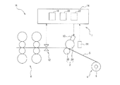
図1は、本実施形態のギャップ制御装置1を備えた熱間圧延ラインHLの概略構成を示す図である。
ギャップ制御装置1は、熱間圧延ライン等、スラブを圧延する圧延ラインに適用する装置であり、一対のピンチロール2に対し、そのギャップ(一対のピンチロール2間の隙間)を制御する装置である。
(First embodiment)
Hereinafter, a first embodiment of the present invention (hereinafter referred to as “the present embodiment”) will be described with reference to the drawings.
(Constitution)
First, the configuration of the pinch roll gap control device according to the present embodiment (which may be referred to as “gap control device” in the following description) will be described with reference to FIGS. 1 and 2.
FIG. 1 is a diagram showing a schematic configuration of a hot rolling line HL provided with a gap control device 1 of the present embodiment.
The gap control device 1 is a device that is applied to a rolling line that rolls a slab, such as a hot rolling line, and is a device that controls the gap (gap between the pair of pinch rolls 2) with respect to the pair of pinch rolls 2. is there.
本実施形態では、圧延ラインの構成を、一例として、スラブを熱間圧延して板厚が3[mm]程度の鋼帯Sを形成し、この鋼帯Sをコイラー4でコイル状に巻き取って、コイル6を形成する構成とした場合を説明する。
ここで、一対のピンチロール2は、仕上圧延機8とコイラー4との間に配置されて、仕上圧延機8よりも、鋼帯Sの搬送方向下流側に配置されており、コイラー4に巻き取られる前の鋼帯Sを厚さ方向から挟持している。
In the present embodiment, as an example of the configuration of the rolling line, a steel strip S having a thickness of about 3 mm is formed by hot rolling a slab, and the steel strip S is wound in a coil shape by the coiler 4. A case where the
Here, the pair of pinch rolls 2 is disposed between the finishing mill 8 and the coiler 4, and is disposed downstream of the finishing mill 8 in the conveying direction of the steel strip S, and is wound around the coiler 4. The steel strip S before being taken is sandwiched from the thickness direction.
また、仕上圧延機8は、仕上圧延機8よりも鋼帯Sの搬送方向上流側に配置された図示しない設備(例えば、加熱炉等)から搬送されてくる鋼帯Sを圧延する設備であり、複数の仕上スタンド(図1中には、二つの仕上スタンドのみを図示)を備えている。
また、一対のピンチロール2は、鋼帯Sの上方に配置した上側ピンチロール2Uと、鋼帯Sの下方に配置した下側ピンチロール2Dを備えている。
Further, the finish rolling mill 8 is a facility for rolling the steel strip S that is transported from a facility (not shown) (for example, a heating furnace) disposed on the upstream side in the transport direction of the steel strip S relative to the finish rolling mill 8. A plurality of finishing stands (only two finishing stands are shown in FIG. 1) are provided.
The pair of pinch rolls 2 includes an
また、上側ピンチロール2Uには、上側ピンチロール2Uを回転させる上側ロール用モータ(図示せず)が接続されており、下側ピンチロール2Dには、下側ピンチロール2Dを回転させる下側ロール用モータ(図示せず)が接続されている。
なお、仕上圧延機8とピンチロール2との間には、仕上圧延機8で圧延した鋼帯Sを冷却しながら搬送するランナウトテーブル(図示せず)等が配置されている。
An upper roll motor (not shown) that rotates the
Between the finish rolling mill 8 and the pinch roll 2, a runout table (not shown) that transports the steel strip S rolled by the finish rolling mill 8 while cooling is disposed.
また、図1中に示すように、ギャップ制御装置1は、ロールギャップ変化機構10と、圧延後板厚検出部12と、抵抗電流値検出部14と、ギャップ制御部16を備えている。
ロールギャップ変化機構10は、一対のピンチロール2のうち少なくとも一方の位置を変化可能なアクチュエータ(図示せず)を用いて形成されている。
なお、本実施形態では、一例として、ロールギャップ変化機構10の構成を、一対のピンチロール2のうち、上側ピンチロール2Uの位置を変化可能なアクチュエータを用いて形成した場合を説明する。
As shown in FIG. 1, the gap control device 1 includes a roll
The roll
In the present embodiment, as an example, a case will be described in which the configuration of the roll
また、ロールギャップ変化機構10は、上側ピンチロール2Uの位置を変化させることにより、一対のピンチロール2の相対位置を変化させて、一対のピンチロール2のギャップを変化させる。
圧延後板厚検出部12は、例えば、非接触で鋼帯Sの厚さ(板厚)を計測可能なX線厚さ計(X線センサ)等を用いて形成されており、仕上圧延機8よりも鋼帯Sの搬送方向下流側に配置されている。すなわち、圧延後板厚検出部12は、仕上圧延機8で圧延された後の鋼帯Sの板厚を検出する。
Further, the roll
The post-rolling sheet thickness detection unit 12 is formed using, for example, an X-ray thickness meter (X-ray sensor) capable of measuring the thickness (sheet thickness) of the steel strip S in a non-contact manner, and is a finish rolling mill It is arrange | positioned rather than 8 in the conveyance direction downstream side of the steel strip S. FIG. That is, the post-rolling plate thickness detection unit 12 detects the plate thickness of the steel strip S after being rolled by the finish rolling mill 8.
また、圧延後板厚検出部12は、仕上圧延機8で圧延された後の鋼帯Sの板厚を検出すると、この検出した板厚を含む情報信号を、ギャップ制御部16へ出力する。
本実施形態では、一例として、圧延後板厚検出部12を、仕上圧延機8よりも、鋼帯Sの搬送方向で、1.5〜2.0[m]下流側へ配置した場合について説明する。
抵抗電流値検出部14は、鋼帯Sを搬送する方向へピンチロール2を回転させるピンチロール回転部(上側ロール用モータ、下側ロール用モータ)が、ピンチロール2の回転速度を鋼帯Sの搬送速度よりも減速させた状態で、ピンチロール回転部に発生する抵抗電流値を検出する。
In addition, when the post-rolling plate thickness detection unit 12 detects the plate thickness of the steel strip S after being rolled by the finish rolling mill 8, the post-rolling plate thickness detection unit 12 outputs an information signal including the detected plate thickness to the gap control unit 16.
In the present embodiment, as an example, the case where the post-rolling sheet thickness detection unit 12 is arranged 1.5 to 2.0 [m] downstream from the finish rolling mill 8 in the conveying direction of the steel strip S will be described. To do.
The resistance current
また、抵抗電流値検出部14は、ピンチロール回転部がピンチロール2の回転速度を鋼帯Sの搬送速度よりも減速させた状態で、ピンチロール回転部に発生する抵抗電流値を検出すると、この検出した抵抗電流値を含む情報信号を、ギャップ制御部16へ出力する。
ここで、上記の抵抗電流は、ピンチロール2の回転速度を鋼帯Sの搬送速度よりも減速させたことによりピンチロール2に対して加わる、鋼帯Sを搬送する回転方向とは逆方向への応力により、ピンチロール回転部(上側ロール用モータ、下側ロール用モータ)に発生する電流である。
Further, the resistance current
Here, the resistance current described above is applied to the pinch roll 2 by reducing the rotational speed of the pinch roll 2 relative to the transport speed of the steel strip S, in the direction opposite to the rotational direction in which the steel strip S is transported. Is a current generated in the pinch roll rotating part (upper roll motor, lower roll motor) due to the stress.
なお、本実施形態では、一例として、抵抗電流値検出部14の構成を、ピンチロール回転部が、一対のピンチロール2の回転速度を鋼帯Sの搬送速度に対して20%以上35%以下の範囲内で減速させた状態で、抵抗電流値を検出する構成とした場合を説明する。その理由は、後述する。
具体的には、搬送されている鋼帯Sの先端が、一対のピンチロール2間を挟持されながら通過してコイラー4に巻きついた後に、上側ロール用モータ及び下側ロール用モータの駆動状態を制御して、上側ピンチロール2U及び下側ピンチロール2Dの回転速度を、鋼帯Sの搬送速度に対して20%以上35%以下の範囲内で減速させる。これにより、上側ロール用モータ及び下側ロール用モータ(ピンチロール回転部)で抵抗電流値を発生させた状態で、抵抗電流値検出部14により、上側ロール用モータ及び下側ロール用モータで発生させた抵抗電流値を検出する。
In this embodiment, as an example, the configuration of the resistance current
Specifically, after the tip of the steel strip S being conveyed passes between the pair of pinch rolls 2 and is wound around the coiler 4, the upper roll motor and the lower roll motor are driven. And the rotational speeds of the
ギャップ制御部16は、例えば、PC(Personal Computer)等を用いて形成されており、ギャップ制御テーブル記憶部18と、変化度合制御部20と、ギャップ検出部22を備えている。
ギャップ制御テーブル記憶部18は、圧延後板厚検出部12から入力された情報信号に基づき、仕上圧延機8で圧延された後の鋼帯Sの板厚を参照する。これに加え、ギャップ制御テーブル記憶部18は、例えば、熱間圧延ラインのオペレータ等により外部から入力された情報や、カメラ等の撮像機構を用いて取得した情報を参照する。さらに、ギャップ制御テーブル記憶部18は、ギャップ検出部22から入力された情報信号に基づき、一対のピンチロール2のギャップを参照する。
The gap control unit 16 is formed using, for example, a PC (Personal Computer) or the like, and includes a gap control
The gap control
そして、ギャップ制御テーブル記憶部18は、上記の参照した情報に基づいて、合格部分板厚と合格部分挟持ギャップとを対応させたデータテーブルであるギャップ制御テーブルを、予め記憶する。
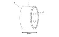
合格部分板厚は、鋼帯Sのうち、図2中に示すように、圧延及び巻き取りが完了した鋼帯Sにおける尾端から予め設定した長さまでの尾端側部分のうち、コイラー4で巻き取られたコイル6の側面からの突出量(鋼帯Sの幅方向への突出量)が、予め設定した突出量閾値未満である部分の少なくとも一部を、圧延後板厚検出部12で検出した板厚である。なお、図2は、尾端側部分が側面から突出した状態のコイル6を示す斜視図である。また、図2中では、コイル6の側面から突出した尾端側部分(以降の説明では、「巻き乱れ部」と記載する場合がある)を、符合24を付して示している。また、図2中では、鋼帯Sの幅方向を、双方向矢印を付して「幅方向」と示している。
And the gap control table memory |
As shown in FIG. 2, among the steel strips S, the acceptable partial plate thickness is the coiler 4 in the tail end side portion from the tail end to the preset length in the steel strip S that has been rolled and rolled up. At least part of the portion where the protruding amount from the side surface of the wound coil 6 (the protruding amount in the width direction of the steel strip S) is less than a preset protruding amount threshold is detected by the post-rolling sheet thickness detection unit 12. The detected plate thickness. FIG. 2 is a perspective view showing the
また、合格部分板厚は、例えば、上限値と下限値で0.1[mm]の範囲を有する値としてもよい。
合格部分挟持ギャップは、尾端側部分のうち、コイラー4で巻き取られたコイル6の側面からの突出量が突出量閾値未満である部分を挟持した状態における、一対のピンチロール2のギャップである。
ここで、コイラー4でコイル状に巻き取られた鋼帯Sの側面から突出した部分の突出量は、熱間圧延ラインのオペレータ等が計測してもよく、カメラ等の撮像機構を用いて計測してもよい。
本実施形態では、一例として、尾端側部分の長さを、約100[m]とした場合を説明する。すなわち、本実施形態では、上記の予め設定した長さを、約100[m]とする。
The acceptable partial plate thickness may be a value having a range of 0.1 [mm] as an upper limit value and a lower limit value, for example.
The acceptable part clamping gap is a gap between the pair of pinch rolls 2 in a state in which a part of the tail end side part that projects from the side surface of the
Here, the protrusion amount of the portion protruding from the side surface of the steel strip S wound in a coil shape by the coiler 4 may be measured by an operator of a hot rolling line or the like, and is measured using an imaging mechanism such as a camera. May be.
In the present embodiment, as an example, a case will be described in which the length of the tail end portion is about 100 [m]. That is, in the present embodiment, the preset length is set to about 100 [m].
また、本実施形態では、一例として、突出量閾値を、10[mm]とした場合を説明する。
変化度合制御部20は、圧延後板厚検出部12から入力された情報信号に基づき、仕上圧延機8で圧延された後の鋼帯Sの板厚を参照するとともに、ギャップ制御テーブル記憶部18に予め記憶されているギャップ制御テーブルを参照する。これにより、変化度合制御部20は、仕上圧延機8が尾端側部分を圧延している状態で圧延後板厚検出部12が検出した尾端側部分の板厚である現在板厚と、合格部分板厚とを比較する。
なお、仕上圧延機8が尾端側部分を圧延している状態は、例えば、鋼帯Sの全長と搬送速度に基づいて検出する。
In this embodiment, as an example, a case where the protrusion amount threshold is set to 10 [mm] will be described.
The degree-of-
In addition, the state which the finishing mill 8 is rolling the tail end side part is detected based on the full length and the conveyance speed of the steel strip S, for example.
そして、変化度合制御部20は、尾端側部分を挟持する一対のピンチロール2のギャップが、現在板厚と等しい合格部分板厚に対応した合格部分挟持ギャップとなるように、上側ピンチロール2Uの変位量を演算する。さらに、演算した上側ピンチロール2Uの変位量に基づいて、一対のピンチロール2の相対位置の変化度合いを制御する指令信号を生成し、この生成した指令信号を、ロールギャップ変化機構10へ出力する。
これにより、変化度合制御部20は、一対のピンチロール2の相対位置を変化させて、一対のピンチロール2のギャップを、現在板厚と等しい合格部分板厚に応じた合格部分挟持ギャップとなるように変化させる。
And the change
Thereby, the degree-of-
また、変化度合制御部20が、上記の指令信号をロールギャップ変化機構10へ出力するタイミングは、尾端側部分のうち、仕上圧延機8が尾端側部分を圧延している状態で現在板厚を検出した部分が、一対のピンチロール2間に挟持されるまでに、一対のピンチロール2のギャップを現在板厚と等しい合格部分板厚に応じた合格部分挟持ギャップとなるように変化させるタイミングとする。すなわち、一対のピンチロール2のギャップを、一対のピンチロール2よりも鋼帯Sの搬送方向上流側において、圧延後板厚検出部12が検出した現在板厚を用いて制御(フィードフォワード制御)可能なタイミングとする。
ギャップ検出部22は、抵抗電流値検出部14から入力された情報信号を参照し、コイル6の側面からの突出量が突出量閾値未満である尾端側部分を一対のピンチロール2が挟持している状態で抵抗電流値検出部12が検出した抵抗電流値に基づいて、一対のピンチロール2のギャップを検出する。
Further, the timing at which the change
The
また、ギャップ検出部22は、検出した一対のピンチロール2のギャップを含む情報信号を、ギャップ制御テーブル記憶部18へ出力する。
ここで、コイル6の側面からの突出量が突出量閾値未満である尾端側部分を一対のピンチロール2が挟持している状態で抵抗電流値検出部12が検出した抵抗電流値は、鋼帯Sの搬送速度に対するピンチロール2の回転速度の減速度合いを同一条件とした場合であっても、ピンチロール2の磨耗の進行度合いに応じて変化する。
Further, the
Here, the resistance current value detected by the resistance current value detection unit 12 in a state in which the pair of pinch rolls 2 is sandwiching the tail end side portion where the protrusion amount from the side surface of the
このため、ギャップ検出部22が検出した一対のピンチロール2のギャップは、鋼帯Sの搬送速度に対するピンチロール2の回転速度の減速度合いを同一条件とした場合であっても、ピンチロール2の磨耗の進行度合いに応じて変化することとなる。
(ピンチロール回転部が一対のピンチロール2の回転速度を鋼帯Sの搬送速度に対して20%以上35%以下の範囲内で減速させた状態で、抵抗電流値検出部14が抵抗電流値を検出する理由)
For this reason, the gap between the pair of pinch rolls 2 detected by the
(With the pinch roll rotating part decelerating the rotational speed of the pair of pinch rolls 2 within a range of 20% or more and 35% or less with respect to the conveying speed of the steel strip S, the resistance current
以下、ピンチロール回転部が一対のピンチロール2の回転速度を鋼帯Sの搬送速度に対して20%以上35%以下の範囲内で減速させた状態で、抵抗電流値検出部14が抵抗電流値を検出する理由を説明する。
本発明の発明者等が、本実施形態と同様の構成である熱間圧延ラインを用いて、上側ロール用モータ及び下側ロール用モータで発生させた抵抗電流値を検出したところ、以下の状態が確認された。
すなわち、ピンチロール回転部が一対のピンチロール2の回転速度を鋼帯Sの搬送速度に対して20%未満で減速させた状態では、ピンチロール回転部が一対のピンチロール2の回転速度を鋼帯Sの搬送速度に対して20%以上で減速させた状態と比較して、上側ロール用モータ及び下側ロール用モータで発生させた抵抗電流値が低く、また、安定しないことが確認された。
In the state where the pinch roll rotating unit decelerates the rotation speed of the pair of pinch rolls 2 within a range of 20% or more and 35% or less with respect to the conveying speed of the steel strip S, the resistance current
When the inventors of the present invention detected the resistance current values generated by the upper roll motor and the lower roll motor using a hot rolling line having the same configuration as that of the present embodiment, the following states were obtained. Was confirmed.
That is, in a state where the rotation speed of the pair of pinch rolls 2 is reduced by less than 20% with respect to the conveying speed of the steel strip S, the pinch roll rotation section sets the rotation speed of the pair of pinch rolls 2 to steel. It was confirmed that the resistance current value generated by the upper roll motor and the lower roll motor was low and not stable as compared with the state where the belt S was decelerated by 20% or more with respect to the transport speed of the belt S. .
このため、ピンチロール回転部が一対のピンチロール2の回転速度を鋼帯Sの搬送速度に対して20%未満で減速させた状態では、ピンチロール回転部が一対のピンチロール2の回転速度を鋼帯Sの搬送速度に対して20%以上で減速させた状態と比較して、抵抗電流値検出部14による抵抗電流値の検出値を、各種制御のパラメータとすることが困難となることが確認された。
For this reason, in a state in which the pinch roll rotating part decelerates the rotation speed of the pair of pinch rolls 2 by less than 20% with respect to the conveying speed of the steel strip S, the pinch roll rotating part increases the rotation speed of the pair of pinch rolls 2. Compared to the state where the steel strip S is decelerated by 20% or more with respect to the conveying speed of the steel strip S, it may be difficult to use the resistance current value detected by the resistance
一方、ピンチロール回転部が一対のピンチロール2の回転速度を鋼帯Sの搬送速度に対して35%を超えて減速させた状態では、ピンチロール回転部が一対のピンチロール2の回転速度を鋼帯Sの搬送速度に対して20%以下で減速させた状態と比較して、一対のピンチロール2で挟持された鋼帯Sに擦り傷等の欠陥が発生する可能性や、コイル6全体に対して、巻き形状の乱れが発生する可能性が増加することが確認された。
以上の理由により、本実施形態では、ピンチロール回転部が一対のピンチロール2の回転速度を鋼帯Sの搬送速度に対して20%以上35%以下の範囲内で減速させた状態で、抵抗電流値検出部14が抵抗電流値を検出する。
On the other hand, in a state in which the pinch roll rotating unit decelerates the rotation speed of the pair of pinch rolls 2 by more than 35% with respect to the conveying speed of the steel strip S, the pinch roll rotating unit increases the rotation speed of the pair of pinch rolls 2. Compared with a state where the steel strip S is decelerated at 20% or less with respect to the conveyance speed, the steel strip S sandwiched between the pair of pinch rolls 2 may be damaged, or the
For the above reasons, in the present embodiment, the pinch roll rotating unit reduces the rotational speed of the pair of pinch rolls 2 within a range of 20% to 35% with respect to the conveying speed of the steel strip S. The
(ピンチロールギャップの制御方法)
以下、図1及び図2を参照して、上記の構成を備えたギャップ制御装置1で行うピンチロールギャップの制御方法(以降の説明では、「ギャップ制御方法」と記載する場合がある)について説明する。
本実施形態のギャップ制御方法は、ギャップ制御テーブル記憶ステップと、圧延後板厚検出ステップと、変化度合制御ステップと、抵抗電流値検出ステップと、ギャップ検出ステップを有している。
ギャップ制御テーブル記憶ステップでは、ギャップ制御テーブルを予め記憶する。
ギャップ制御テーブルは、上述した合格部分板厚と合格部分挟持ギャップとを対応させたデータテーブルである。
(Pinch roll gap control method)
Hereinafter, with reference to FIG. 1 and FIG. 2, a pinch roll gap control method (which may be referred to as “gap control method” in the following description) performed by the gap control device 1 having the above-described configuration will be described. To do.
The gap control method of this embodiment has a gap control table storage step, a post-rolling sheet thickness detection step, a change degree control step, a resistance current value detection step, and a gap detection step.
In the gap control table storage step, the gap control table is stored in advance.
The gap control table is a data table in which the above-mentioned acceptable part plate thickness and the acceptable part clamping gap are associated with each other.
圧延後板厚検出ステップでは、仕上圧延機8とピンチロール2との間における鋼帯Sの板厚を検出する。
変化度合制御ステップでは、尾端側部分を挟持する一対のピンチロール2のギャップが、仕上圧延機8が尾端側部分を圧延している状態で圧延後板厚検出ステップにおいて検出した尾端側部分の板厚と等しい合格部分板厚に対応した合格部分挟持ギャップとなるように、一対のピンチロール2のギャップの変化度合いを制御する。
In the post-rolling plate thickness detection step, the plate thickness of the steel strip S between the finish rolling mill 8 and the pinch roll 2 is detected.
In the change degree control step, the gap between the pair of pinch rolls 2 sandwiching the tail end portion is detected at the post-rolling thickness detection step in the state in which the finishing mill 8 is rolling the tail end portion. The degree of change in the gap between the pair of pinch rolls 2 is controlled so as to obtain an acceptable partial clamping gap corresponding to an acceptable partial plate thickness equal to the partial thickness.
本実施形態では、変化度合制御ステップにおいて、上側ピンチロール2Uの位置の変化度合いを制御することにより、一対のピンチロール2のギャップの変化度合いを制御する場合を説明する。
抵抗電流値検出ステップでは、ピンチロール回転部がピンチロール2の回転速度を鋼帯Sの搬送速度よりも減速させた状態で、ピンチロール回転部に発生する抵抗電流値を検出する。
In the present embodiment, a case will be described in which the change degree of the gap between the pair of pinch rolls 2 is controlled by controlling the change degree of the position of the
In the resistance current value detection step, the resistance current value generated in the pinch roll rotating part is detected in a state where the pinch roll rotating part decelerates the rotation speed of the pinch roll 2 from the conveying speed of the steel strip S.
本実施形態では、一例として、抵抗電流値検出ステップにおいて、ピンチロール回転部がピンチロール2の回転速度を鋼帯Sの搬送速度に対して20%以上35%以下の範囲内で減速させた状態で、抵抗電流値を検出する場合を説明する。
ギャップ検出ステップでは、コイル6の側面からの突出量が突出量閾値未満である尾端側部分を一対のピンチロール2が挟持している状態で、抵抗電流値検出ステップにおいて検出した抵抗電流値に基づいて、一対のピンチロール2のギャップを検出する。
In the present embodiment, as an example, in the resistance current value detection step, the pinch roll rotating unit decelerates the rotation speed of the pinch roll 2 within a range of 20% to 35% with respect to the conveyance speed of the steel strip S. The case where the resistance current value is detected will be described.
In the gap detection step, the resistance current value detected in the resistance current value detection step in a state where the pair of pinch rolls 2 is sandwiching the tail end side portion where the protrusion amount from the side surface of the
(動作・作用)
以下、図1及び図2を参照して、上記の構成を備えたギャップ制御装置1と、このギャップ制御装置1で行うギャップ制御方法の動作・作用を説明する。
本実施形態のギャップ制御装置1を備えた熱間圧延ラインHLにおいて、圧延した鋼帯Sによりコイル6を製造する際には、まず、仕上圧延機8によりスラブを熱間圧延して板厚が3[mm]程度の鋼帯Sを形成し、この圧延した鋼帯Sを、一対のピンチロール2により、厚さ方向から挟持して、コイラー4へ誘導する。
(Operation / Action)
Hereinafter, with reference to FIG.1 and FIG.2, the operation | movement and effect | action of the gap control apparatus 1 provided with said structure and the gap control method performed with this gap control apparatus 1 are demonstrated.
In the hot rolling line HL provided with the gap control device 1 of the present embodiment, when the
一般的に、熱間圧延ラインHLでは、鋼帯Sの板厚が、鋼帯Sへ加わる荷重、鋼帯Sの搬送速度、鋼帯Sの温度、鋼帯Sの張力等により、鋼帯Sの全長内で変動する場合が多い。
ここで、圧延後板厚検出部12が検出した板厚が、所望の板厚(3[mm]程度)から離れた値である場合、一対のピンチロール2を通過した鋼帯Sの板厚が所望の板厚となるように、一対のピンチロール2のギャップや、ピンチロール2の回転速度を変化させる。
Generally, in the hot rolling line HL, the thickness of the steel strip S depends on the load applied to the steel strip S, the conveying speed of the steel strip S, the temperature of the steel strip S, the tension of the steel strip S, and the like. Often fluctuates within the total length of
Here, when the plate thickness detected by the post-rolling plate thickness detection unit 12 is a value away from a desired plate thickness (about 3 [mm]), the plate thickness of the steel strip S that has passed through the pair of pinch rolls 2. , The gap between the pair of pinch rolls 2 and the rotational speed of the pinch rolls 2 are changed so as to have a desired thickness.
また、本実施形態では、尾端側部分を挟持する一対のピンチロール2のギャップが、仕上圧延機8が尾端側部分を圧延している状態で圧延後板厚検出部12が検出した尾端側部分の板厚と等しい合格部分板厚に対応した合格部分挟持ギャップとなるように、変化度合制御部20が、一対のピンチロール2のギャップの変化度合いを制御する(変化度合制御ステップ)。
これにより、尾端側部分が仕上圧延機8から抜けた際のピンチロール2のギャップが、巻き乱れ部24の突出量が予め設定した突出量閾値(10[mm])未満である場合の、合格部分板厚に応じたギャップとなる。
Further, in the present embodiment, the gap between the pair of pinch rolls 2 that sandwich the tail end portion is detected by the post-rolling sheet thickness detection unit 12 in a state where the finishing mill 8 is rolling the tail end portion. The degree-of-
Thereby, the gap of the pinch roll 2 when the tail end side part has come out of the finish rolling mill 8 is when the protrusion amount of the
このため、尾端側部分が仕上圧延機8から抜けた際には、合格部分板厚に応じたギャップとなっている一対のピンチロール2により、尾端側部分が仕上圧延機8から抜けた鋼帯Sが保持されることとなる。
したがって、尾端側部分が仕上圧延機8から抜けた際には、尾端側部分に付与される後方張力が適切な値となり、仕上圧延機8とピンチロール2との間において、尾端側部分の蛇行を抑制することが可能となるため、コイル6の巻き形状の乱れを抑制することが可能となる。
For this reason, when the tail end side part has come out of the finish rolling mill 8, the tail end side part has come out of the finish rolling mill 8 by the pair of pinch rolls 2 serving as a gap corresponding to the acceptable part plate thickness. The steel strip S is held.
Therefore, when the tail end side part comes out of the finishing mill 8, the rear tension applied to the tail end side part becomes an appropriate value, and the tail end side is between the finishing mill 8 and the pinch roll 2. Since it is possible to suppress the meandering of the portion, it is possible to suppress the disorder of the winding shape of the
また、本実施形態では、ギャップ検出部22が、尾端側部分のうち上記の突出量が突出量閾値未満である部分を、一対のピンチロール2が挟持している状態で、抵抗電流値検出部14が検出した抵抗電流値に基づいて、一対のピンチロール2のギャップを検出する(ギャップ検出ステップ)。
このため、継続的な使用等によりピンチロール2の磨耗が進行した場合であっても、磨耗の進行度合いに応じて変化する抵抗電流値に基づいて、一対のピンチロール2のギャップを検出することが可能となる。
以上により、本実施形態では、定常状態、すなわち、搬送されている鋼帯Sの先端が一対のピンチロール2間を挟持されながら通過してコイラー4に巻きついた後から、鋼帯Sが仕上圧延機8で圧延されている状態に加え、尾端側部分が仕上圧延機8から抜けた際においても、一対のピンチロール2のギャップを適切な値とすることが可能となる。
Further, in the present embodiment, the
For this reason, even when the wear of the pinch roll 2 has progressed due to continuous use or the like, the gap between the pair of pinch rolls 2 is detected based on the resistance current value that changes according to the progress of the wear. Is possible.
As described above, in the present embodiment, the steel strip S is finished after being in a steady state, that is, after the tip of the steel strip S being conveyed passes between the pair of pinch rolls 2 and winds around the coiler 4. In addition to the state of being rolled by the rolling mill 8, the gap between the pair of pinch rolls 2 can be set to an appropriate value even when the tail end side portion is removed from the finish rolling mill 8.
これにより、鋼帯Sには、全体に亘って適切な値の後方張力が付与されることとなり、鋼帯Sの全体に亘って、仕上圧延機8とピンチロール2との間における蛇行を抑制することが可能となる。
このため、鋼帯Sの全体に亘って、コイル6の巻き形状の乱れを抑制することが可能となる。
なお、尾端側部分が仕上圧延機8から抜けた後は、例えば、ピンチロール回転部が一対のピンチロール2の回転速度を鋼帯Sの搬送速度に対して5%以上30%以下の範囲内で減速させた状態で、鋼帯Sの搬送及びコイラー4による鋼帯Sの巻取りを行うことにより、鋼帯Sに対する後方張力の付与を継続する。
As a result, the steel strip S is provided with an appropriate rearward tension throughout the entire steel strip S, and the meandering between the finishing mill 8 and the pinch roll 2 is suppressed over the entire steel strip S. It becomes possible to do.
For this reason, it becomes possible to suppress disturbance of the winding shape of the
In addition, after the tail end side part has come out of the finish rolling mill 8, for example, the pinch roll rotating unit has a rotation speed of the pair of pinch rolls 2 within a range of 5% to 30% with respect to the conveying speed of the steel strip S. In this state, the steel strip S is transported and the steel strip S is wound by the coiler 4, so that the rear tension is continuously applied to the steel strip S.
(第一実施形態の効果)
以下、本実施形態の効果を列挙する。
(1)本実施形態のギャップ制御装置1では、変化度合制御部20が、尾端側部分を挟持する一対のピンチロール2のギャップが、仕上圧延機8が尾端側部分を圧延している状態で圧延後板厚検出部12が検出した尾端側部分の板厚と等しい合格部分板厚に対応した合格部分挟持ギャップとなるように、一対のピンチロール2のギャップの変化度合いを制御する。
(Effects of the first embodiment)
The effects of this embodiment are listed below.
(1) In the gap control apparatus 1 of this embodiment, the change
このため、尾端側部分が仕上圧延機8から抜けた際の、一対のピンチロール2のギャップを、尾端側部分の突出量が予め設定した突出量閾値未満である場合の、合格部分板厚に応じたギャップに制御することが可能となる。
その結果、尾端側部分が仕上圧延機8から抜けた際に、適切な後方張力を鋼帯Sに付与することが可能となるため、仕上圧延機8を抜けた後の、尾端側部分の蛇行を抑制することが可能となる。
これにより、コイル6の巻き形状の乱れを抑制して、耳折れや耳切れの発生を抑制し、歩留りや製造効率の低下を抑制することが可能となる。
For this reason, when the tail end side portion is removed from the finishing mill 8, the gap between the pair of pinch rolls 2 is obtained when the projection amount of the tail end side portion is less than a preset projection amount threshold value. It is possible to control the gap according to the thickness.
As a result, when the tail end side portion comes out of the finish rolling mill 8, it becomes possible to apply an appropriate rear tension to the steel strip S, so that the tail end side portion after exiting the finishing mill 8 Can be suppressed.
As a result, it is possible to suppress disturbance of the winding shape of the
(2)本実施形態のギャップ制御装置1では、ギャップ検出部22が、尾端側部分のうちコイラー4で巻き取られたコイル6の側面からの突出量が予め設定した突出量閾値未満である部分を一対のピンチロール2が挟持している状態で、抵抗電流値検出部12が検出した抵抗電流値に基づいて、一対のピンチロール2のギャップを検出する。
このため、継続的な使用等によりピンチロール2の磨耗が進行した場合であっても、磨耗の進行度合いに応じて変化する抵抗電流値に基づいて、一対のピンチロール2のギャップを検出することが可能となる。
その結果、継続的な使用等によりピンチロール2の磨耗が進行した場合であっても、尾端側部分が仕上圧延機8から抜けた際に、適切な後方張力を安定して鋼帯Sに付与することが可能となるため、仕上圧延機8を抜けた後の、尾端側部分の蛇行を、長期に亘って抑制することが可能となる。
(2) In the gap control device 1 of the present embodiment, the
For this reason, even when the wear of the pinch roll 2 has progressed due to continuous use or the like, the gap between the pair of pinch rolls 2 is detected based on the resistance current value that changes according to the progress of the wear. Is possible.
As a result, even when the wear of the pinch roll 2 has progressed due to continuous use or the like, when the tail end side portion has come out of the finish rolling mill 8, the appropriate rear tension is stably applied to the steel strip S. Since it becomes possible to give, it becomes possible to suppress the meandering of the tail end side part after leaving the finishing mill 8 over a long period of time.
(3)本実施形態のギャップ制御装置1では、抵抗電流値検出部14が、ピンチロール回転部がピンチロール2の回転速度を鋼帯Sの搬送速度に対して20%以上35%以下の範囲内で減速させた状態で、抵抗電流値を検出する。
このため、ピンチロール回転部がピンチロール2の回転速度を鋼帯の搬送速度に対して20%未満で減速させた状態で抵抗電流値を検出する場合と比較して、抵抗電流値の検出精度を安定させることが可能となる。
(3) In the gap control device 1 of the present embodiment, the resistance current
For this reason, compared with the case where a resistance current value is detected in a state in which the pinch roll rotating portion decelerates the rotation speed of the pinch roll 2 by less than 20% with respect to the conveyance speed of the steel strip, the detection accuracy of the resistance current value is increased. Can be stabilized.
これに加え、ピンチロール回転部がピンチロール2の回転速度を鋼帯の搬送速度に対して35%を超えて減速させた状態で抵抗電流値を検出する場合と比較して、一対のピンチロール2で挟持された鋼帯Sに擦り傷等の欠陥が発生する可能性や、コイル6全体に対して、巻き形状の乱れが発生する可能性を低減させることが可能となる。
その結果、ピンチロール回転部がピンチロール2の回転速度を鋼帯の搬送速度に対して20%未満及び35%を超えて減速させた状態で、抵抗電流値を検出する場合と比較して、ピンチロール2の磨耗に応じて適切な後方張力を鋼帯Sに付与することが可能となるとともに、コイル6の品質低下を抑制することが可能となる。
In addition to this, a pair of pinch rolls is compared with the case where the pinch roll rotating part detects the resistance current value in a state where the rotation speed of the pinch roll 2 is reduced by more than 35% with respect to the conveying speed of the steel strip. It is possible to reduce the possibility that defects such as scratches will occur in the steel strip S sandwiched between 2 and the possibility that the winding shape will be disturbed with respect to the
As a result, in a state where the pinch roll rotating part decelerates the rotation speed of the pinch roll 2 by less than 20% and more than 35% with respect to the conveying speed of the steel strip, compared to the case of detecting the resistance current value, Appropriate rear tension can be applied to the steel strip S in accordance with the wear of the pinch roll 2, and deterioration of the quality of the
(4)本実施形態のギャップ制御方法では、変化度合制御ステップにおいて、尾端側部分を挟持する一対のピンチロール2のギャップが、仕上圧延機8が尾端側部分を圧延している状態で圧延後板厚検出ステップにおいて検出した尾端側部分の板厚と等しい合格部分板厚に対応した合格部分挟持ギャップとなるように、一対のピンチロール2のギャップの変化度合いを制御する。
その結果、尾端側部分が仕上圧延機8から抜けた際に、適切な後方張力を鋼帯Sに付与することが可能となるため、仕上圧延機8を抜けた後の、尾端側部分の蛇行を抑制することが可能となり、コイル6の巻き形状の乱れを抑制して、耳折れや耳切れの発生を抑制し、歩留りや製造効率の低下を抑制することが可能となる。
(4) In the gap control method of this embodiment, in the change degree control step, the gap between the pair of pinch rolls 2 sandwiching the tail end side portion is in a state where the finishing mill 8 is rolling the tail end side portion. The degree of change in the gap between the pair of pinch rolls 2 is controlled so as to obtain an acceptable portion clamping gap corresponding to an acceptable partial plate thickness equal to the plate thickness of the tail end side portion detected in the post-rolling plate thickness detection step.
As a result, when the tail end side portion comes out of the finish rolling mill 8, it becomes possible to apply an appropriate rear tension to the steel strip S, so that the tail end side portion after exiting the finishing mill 8 It is possible to suppress the meandering of the
(5)本実施形態のギャップ制御方法では、ギャップ検出ステップにおいて、尾端側部分のうちコイラー4で巻き取られたコイル6の側面からの突出量が予め設定した突出量閾値未満である部分を一対のピンチロール2が挟持している状態で、抵抗電流値検出ステップにおいて検出した抵抗電流値に基づいて、一対のピンチロール2のギャップを検出する。
その結果、継続的な使用等によりピンチロール2の磨耗が進行した場合であっても、尾端側部分が仕上圧延機8から抜けた際に、適切な後方張力を安定して鋼帯Sに付与することが可能となるため、仕上圧延機8を抜けた後の、尾端側部分の蛇行を、長期に亘って抑制することが可能となる。
(5) In the gap control method of the present embodiment, in the gap detection step, a portion of the tail end side portion where the protrusion amount from the side surface of the
As a result, even when the wear of the pinch roll 2 has progressed due to continuous use or the like, when the tail end side portion has come out of the finish rolling mill 8, the appropriate rear tension is stably applied to the steel strip S. Since it becomes possible to give, it becomes possible to suppress the meandering of the tail end side part after leaving the finishing mill 8 over a long period of time.
(6)本実施形態のギャップ制御方法では、抵抗電流値検出ステップにおいて、ピンチロール回転部がピンチロール2の回転速度を鋼帯Sの搬送速度に対して20%以上35%以下の範囲内で減速させた状態で、抵抗電流値を検出する。
その結果、ピンチロール回転部がピンチロール2の回転速度を鋼帯の搬送速度に対して20%未満及び35%を超えて減速させた状態で、抵抗電流値を検出する場合と比較して、ピンチロール2の磨耗に応じて適切な後方張力を鋼帯Sに付与することが可能となるとともに、コイル6の品質低下を抑制することが可能となる。
(6) In the gap control method of the present embodiment, in the resistance current value detection step, the pinch roll rotating part sets the rotation speed of the pinch roll 2 within a range of 20% or more and 35% or less with respect to the conveying speed of the steel strip S. The resistance current value is detected in the decelerated state.
As a result, in a state where the pinch roll rotating part decelerates the rotation speed of the pinch roll 2 by less than 20% and more than 35% with respect to the conveying speed of the steel strip, compared to the case of detecting the resistance current value, Appropriate rear tension can be applied to the steel strip S in accordance with the wear of the pinch roll 2, and deterioration of the quality of the
(変形例)
以下、本実施形態の変形例を列挙する。
(1)本実施形態では、尾端側部分の長さを約100[m]としたが、尾端側部分の長さは、これに限定するものではなく、製品に要求される仕様に応じて、適宜変更可能である。
(2)本実施形態では、突出量閾値を10[mm]としたが、突出量閾値は、これに限定するものではなく、製品に要求される仕様に応じて、例えば、5[mm]と設定するなど、適宜変更可能である。
(Modification)
Hereinafter, modifications of the present embodiment will be listed.
(1) In this embodiment, the length of the tail end side portion is about 100 [m], but the length of the tail end side portion is not limited to this, and depends on the specifications required for the product. And can be changed as appropriate.
(2) In the present embodiment, the protrusion amount threshold is set to 10 [mm]. However, the protrusion amount threshold is not limited to this, and may be, for example, 5 [mm] according to the specifications required for the product. It can be changed as appropriate, such as setting.
(実施例1)
以下、図1及び図2を参照しつつ、比較例及び本発明例のギャップ制御装置1を備えた熱間圧延ラインHLにおいて、圧延した鋼帯S(板厚2[mm])により製造したコイル6に対し、歩留りを比較した結果について説明する。
なお、本発明例のギャップ制御装置1及び熱間圧延ラインHLの構成は、上述した第一実施形態と同様である。
Example 1
Hereinafter, with reference to FIG. 1 and FIG. 2, in the hot rolling line HL provided with the gap control device 1 of the comparative example and the example of the present invention, the coil manufactured by the rolled steel strip S (plate thickness 2 [mm]) 6 is compared with the results of yield comparison.
In addition, the structure of the gap control apparatus 1 of this invention example and the hot rolling line HL is the same as that of 1st embodiment mentioned above.
一方、比較例のギャップ制御装置及び熱間圧延ラインの構成は、ギャップ制御テーブル記憶部18及び変化度合制御部20を備えていない点を除き、第一実施形態のギャップ制御装置及び熱間圧延ラインと同様の構成である。
本発明例のギャップ制御装置1を備えた熱間圧延ラインHLで製造したコイル6は、耳折れや耳切れが発生していなかったため、尾端側部分(約100[m])を切り捨てる必要が無かった。
On the other hand, the configurations of the gap control device and the hot rolling line of the comparative example are not provided with the gap control
In the
一方、比較例のギャップ制御装置を備えた熱間圧延ラインで製造したコイルは、20コイル中のうち1コイルで、尾端側部分(約100[m])に耳折れや耳切れが発生していたため、尾端側部分を切り捨てることとなった。
これに対し、本発明例のギャップ制御装置1を備えた熱間圧延ラインHLで製造したコイル6には、不良部分が発生していない。
このため、比較例及び本発明例のギャップ制御装置1を備えた熱間圧延ラインHLにおいて製造したコイル6に対し、歩留りを比較した結果は、本発明例で製造したコイル6の歩留りが、比較例で製造したコイル6の歩留りと比較して、約0.49[%]向上したことが確認された。
On the other hand, the coil manufactured in the hot rolling line equipped with the gap control device of the comparative example is one coil out of 20 coils, and the tail end side portion (about 100 [m]) is bent or cut off. As a result, the tail end was cut off.
On the other hand, the defective part has not generate | occur | produced in the
For this reason, the results of comparing the yields of the
(実施例2)
以下、図1及び図2を参照しつつ、比較例及び本発明例のギャップ制御装置1を備えた熱間圧延ラインHLにおいて、圧延した鋼帯S(板厚3[mm]以下)により製造したコイル6に対し、歩留りを比較した結果について説明する。
なお、本発明例のギャップ制御装置1及び熱間圧延ラインHLの構成は、上述した第一実施形態と同様である。
(Example 2)
Hereinafter, with reference to FIG. 1 and FIG. 2, in the hot rolling line HL provided with the gap control apparatus 1 of the comparative example and the example of the present invention, the steel strip S was manufactured using a rolled steel strip S (plate thickness of 3 [mm] or less). The result of comparing the yield with respect to the
In addition, the structure of the gap control apparatus 1 of this invention example and the hot rolling line HL is the same as that of 1st embodiment mentioned above.
一方、比較例のギャップ制御装置及び熱間圧延ラインの構成は、ギャップ制御テーブル記憶部18及び変化度合制御部20を備えていない点を除き、第一実施形態のギャップ制御装置及び熱間圧延ラインと同様の構成である。
なお、本実施例では、尾端側部分が仕上圧延機8から抜けた際の、鋼帯Sの搬送速度(通板速度)を、約600[mpm]とした。
本本発明例のギャップ制御装置1を備えた熱間圧延ラインHLで製造したコイル6は、耳折れや耳切れが発生していなかったため、尾端側部分(約100[m])を切り捨てる必要が無かった。
On the other hand, the configurations of the gap control device and the hot rolling line of the comparative example are not provided with the gap control
In this example, the conveyance speed (sheet feeding speed) of the steel strip S when the tail end side portion was removed from the finishing mill 8 was about 600 [mpm].
In the
一方、比較例のギャップ制御装置を備えた熱間圧延ラインで製造したコイルは、尾端側部分(約100[m])に耳折れや耳切れが発生していたため、尾端側部分を切り捨てることとなった。
これに対し、本発明例のギャップ制御装置1を備えた熱間圧延ラインHLで製造したコイル6には、不良部分が発生していない。
このため、比較例及び本発明例のギャップ制御装置1を備えた熱間圧延ラインHLにおいて製造したコイル6に対し、歩留りを比較した結果は、本発明例で製造したコイル6の歩留りが、比較例で製造したコイル6の歩留りと比較して、約0.12[%]向上したことが確認された。
On the other hand, since the coil manufactured by the hot rolling line provided with the gap control device of the comparative example had the ear end portion (about 100 [m]) with the ear fold or the ear break, the tail end side portion was cut off. It became a thing.
On the other hand, the defective part has not generate | occur | produced in the
For this reason, the results of comparing the yields of the
1 ギャップ制御装置
2 ピンチロール
2U 上側ピンチロール
2D 下側ピンチロール
4 コイラー
6 コイル
8 仕上圧延機
10 ロールギャップ変化機構
12 圧延後板厚検出部
14 抵抗電流値検出部
16 ギャップ制御部
18 ギャップ制御テーブル記憶部
20 変化度合制御部
22 ギャップ検出部
24 巻き乱れ部
HL 熱間圧延ライン
S 鋼帯
DESCRIPTION OF SYMBOLS 1 Gap control apparatus 2
Claims (6)
前記一対のピンチロールのギャップを変化させるロールギャップ変化機構と、
前記ロールギャップ変化機構による前記ギャップの変化度合いを制御する変化度合制御部と、
前記仕上圧延機と前記ピンチロールとの間で前記鋼帯の板厚を検出する圧延後板厚検出部と、
前記圧延及び巻き取りが完了した鋼帯における尾端から予め設定した長さまでの尾端側部分のうち前記コイラーで巻き取られたコイルの側面からの突出量が予め設定した突出量閾値未満である部分の少なくとも一部を前記圧延後板厚検出部で検出した合格部分板厚と、前記突出量が前記突出量閾値未満である前記尾端側部分を挟持した前記一対のピンチロールのギャップである合格部分挟持ギャップと、を対応させたデータテーブルであるギャップ制御テーブルを予め記憶するギャップ制御テーブル記憶部と、を備え、
前記変化度合制御部は、前記尾端側部分を挟持する前記一対のピンチロールのギャップが、前記仕上圧延機が前記尾端側部分を圧延している状態で前記圧延後板厚検出部が検出した尾端側部分の板厚と等しい前記合格部分板厚に対応した前記合格部分挟持ギャップとなるように、前記変化度合いを制御することを特徴とするピンチロールギャップの制御装置。 A pinch roll gap control device that controls a gap between a pair of pinch rolls that are disposed between a finish rolling mill that rolls a steel strip being conveyed and a coiler and sandwiches the steel strip before being wound around the coiler. Because
A roll gap changing mechanism for changing a gap between the pair of pinch rolls;
A degree-of-change control unit that controls the degree of change of the gap by the roll gap change mechanism;
A post-rolling plate thickness detection unit that detects a plate thickness of the steel strip between the finish rolling mill and the pinch roll,
The protrusion amount from the side surface of the coil wound by the coiler in the tail end side portion from the tail end to the preset length in the steel strip that has been rolled and wound is less than a preset protrusion amount threshold value. An acceptable partial plate thickness in which at least a part of the portion is detected by the post-rolling plate thickness detection unit, and a gap between the pair of pinch rolls sandwiching the tail end side portion in which the protruding amount is less than the protruding amount threshold A gap control table storage unit that stores in advance a gap control table, which is a data table corresponding to the accepted part clamping gap,
The change degree control unit detects the gap between the pair of pinch rolls sandwiching the tail end side portion, and the post-rolling sheet thickness detection unit detects that the finishing mill is rolling the tail end side portion. The pinch roll gap control device is characterized in that the degree of change is controlled so that the accepted portion clamping gap corresponding to the accepted partial plate thickness equal to the plate thickness of the tail end side portion.
前記突出量が前記突出量閾値未満である前記尾端側部分を前記一対のピンチロールが挟持している状態で前記抵抗電流値検出部が検出した抵抗電流値に基づいて前記ギャップを検出するギャップ検出部と、を備えることを特徴とする請求項1に記載したピンチロールギャップの制御装置。 A resistance current value detection unit that detects a resistance current value generated in the pinch roll rotating unit in a state where the pinch roll rotating unit that rotates the pinch roll decelerates the rotation speed of the pinch roll from the conveying speed of the steel strip. When,
A gap for detecting the gap based on a resistance current value detected by the resistance current value detection unit in a state where the pair of pinch rolls holds the tail end side portion where the protrusion amount is less than the protrusion amount threshold. The pinch roll gap control device according to claim 1, further comprising: a detection unit.
前記圧延及び巻き取りが完了した鋼帯における尾端から予め設定した長さまでの尾端側部分のうち前記コイラーで巻き取られたコイルの側面からの突出量が予め設定した突出量閾値未満である部分の少なくとも一部の板厚を前記仕上圧延機と前記ピンチロールとの間で検出した合格部分板厚と、前記突出量が前記突出量閾値未満である前記尾端側部分を挟持した前記一対のピンチロールのギャップである合格部分挟持ギャップと、を対応させたデータテーブルであるギャップ制御テーブルを予め記憶するギャップ制御テーブル記憶ステップと、
前記仕上圧延機と前記ピンチロールとの間で前記鋼帯の板厚を検出する圧延後板厚検出ステップと、
前記尾端側部分を挟持する前記一対のピンチロールのギャップが、前記仕上圧延機が前記尾端側部分を圧延している状態で前記圧延後板厚検出ステップにおいて検出した尾端側部分の板厚と等しい前記合格部分板厚に対応した前記合格部分挟持ギャップとなるように、前記ギャップの変化度合いを制御する変化度合制御ステップと、を有することを特徴とするピンチロールギャップの制御方法。 A pinch roll gap control method for controlling a gap between a pair of pinch rolls arranged between a finish rolling mill for rolling a steel strip being conveyed and a coiler and sandwiching the steel strip before being wound around the coiler. Because
The protrusion amount from the side surface of the coil wound by the coiler in the tail end side portion from the tail end to the preset length in the steel strip that has been rolled and wound is less than a preset protrusion amount threshold value. The pair of parts sandwiching the tail end side part in which the plate thickness is detected between the finish rolling mill and the pinch roll and the protruding amount is less than the protruding amount threshold. A gap control table storage step for storing in advance a gap control table, which is a data table corresponding to the accepted part clamping gap which is the gap of the pinch roll of
A post-rolling thickness detection step for detecting the thickness of the steel strip between the finish rolling mill and the pinch roll;
The gap between the pair of pinch rolls sandwiching the tail end side portion is detected in the post-rolling plate thickness detection step in the state where the finishing mill is rolling the tail end side portion. And a change degree control step of controlling the degree of change of the gap so as to be the accepted part clamping gap corresponding to the accepted part plate thickness equal to the thickness.
前記突出量が前記突出量閾値未満である前記尾端側部分を前記一対のピンチロールが挟持している状態で前記抵抗電流値検出ステップにおいて検出した抵抗電流値に基づいて、前記ギャップを検出するギャップ検出ステップと、を有することを特徴とする請求項4に記載したピンチロールギャップの制御方法。 A resistance current value detecting step of detecting a resistance current value generated in the pinch roll rotating unit in a state where the pinch roll rotating unit rotating the pinch roll reduces the rotation speed of the pinch roll from the conveying speed of the steel strip. When,
The gap is detected based on the resistance current value detected in the resistance current value detection step in a state where the pair of pinch rolls holds the tail end side portion where the protrusion amount is less than the protrusion amount threshold. 5. The pinch roll gap control method according to claim 4, further comprising a gap detection step.
Priority Applications (1)
| Application Number | Priority Date | Filing Date | Title |
|---|---|---|---|
| JP2011273590A JP2013123733A (en) | 2011-12-14 | 2011-12-14 | Controller and control method for pinch roll gap |
Applications Claiming Priority (1)
| Application Number | Priority Date | Filing Date | Title |
|---|---|---|---|
| JP2011273590A JP2013123733A (en) | 2011-12-14 | 2011-12-14 | Controller and control method for pinch roll gap |
Publications (1)
| Publication Number | Publication Date |
|---|---|
| JP2013123733A true JP2013123733A (en) | 2013-06-24 |
Family
ID=48775312
Family Applications (1)
| Application Number | Title | Priority Date | Filing Date |
|---|---|---|---|
| JP2011273590A Pending JP2013123733A (en) | 2011-12-14 | 2011-12-14 | Controller and control method for pinch roll gap |
Country Status (1)
| Country | Link |
|---|---|
| JP (1) | JP2013123733A (en) |
Cited By (7)
| Publication number | Priority date | Publication date | Assignee | Title |
|---|---|---|---|---|
| CN104624723A (en) * | 2015-01-30 | 2015-05-20 | 广西柳州银海铝业股份有限公司 | Method for controlling moving pinch roll in strip coiling process |
| JP2015147227A (en) * | 2014-02-05 | 2015-08-20 | Jfeスチール株式会社 | Winding control method for hot-rolled steel sheet, and winding control device therefor |
| CN105583237A (en) * | 2016-01-15 | 2016-05-18 | 山西太钢不锈钢股份有限公司 | Hot continuous rolling thick-gauge carbon steel reeling pinch roll variable pressure control method |
| JP2017011023A (en) * | 2015-06-18 | 2017-01-12 | 株式会社Screenホールディングス | Substrate processing apparatus and substrate processing method |
| CN106694623A (en) * | 2016-12-27 | 2017-05-24 | 振石集团东方特钢有限公司 | Recoiling machine EPC system deviation rectification control method |
| CN113305177A (en) * | 2021-05-12 | 2021-08-27 | 首钢京唐钢铁联合有限责任公司 | Coiling machine, method and device for clearing tracking information of plate coil of coiling machine and storage medium |
| CN113388936A (en) * | 2021-05-28 | 2021-09-14 | 杭州余杭区闯洲丝绸厂 | Super-soft ultrathin fencing cloth and manufacturing method thereof |
-
2011
- 2011-12-14 JP JP2011273590A patent/JP2013123733A/en active Pending
Cited By (9)
| Publication number | Priority date | Publication date | Assignee | Title |
|---|---|---|---|---|
| JP2015147227A (en) * | 2014-02-05 | 2015-08-20 | Jfeスチール株式会社 | Winding control method for hot-rolled steel sheet, and winding control device therefor |
| CN104624723A (en) * | 2015-01-30 | 2015-05-20 | 广西柳州银海铝业股份有限公司 | Method for controlling moving pinch roll in strip coiling process |
| JP2017011023A (en) * | 2015-06-18 | 2017-01-12 | 株式会社Screenホールディングス | Substrate processing apparatus and substrate processing method |
| CN105583237A (en) * | 2016-01-15 | 2016-05-18 | 山西太钢不锈钢股份有限公司 | Hot continuous rolling thick-gauge carbon steel reeling pinch roll variable pressure control method |
| CN106694623A (en) * | 2016-12-27 | 2017-05-24 | 振石集团东方特钢有限公司 | Recoiling machine EPC system deviation rectification control method |
| CN106694623B (en) * | 2016-12-27 | 2018-08-07 | 振石集团东方特钢有限公司 | A kind of coiling machine EPC system correction control method |
| CN113305177A (en) * | 2021-05-12 | 2021-08-27 | 首钢京唐钢铁联合有限责任公司 | Coiling machine, method and device for clearing tracking information of plate coil of coiling machine and storage medium |
| CN113388936A (en) * | 2021-05-28 | 2021-09-14 | 杭州余杭区闯洲丝绸厂 | Super-soft ultrathin fencing cloth and manufacturing method thereof |
| CN113388936B (en) * | 2021-05-28 | 2023-11-03 | 杭州余杭区闯洲丝绸厂 | Ultra-soft ultrathin rapier-shooting cloth and manufacturing method thereof |
Similar Documents
| Publication | Publication Date | Title |
|---|---|---|
| JP2013123733A (en) | Controller and control method for pinch roll gap | |
| JPH0513723B2 (en) | ||
| JP5801042B2 (en) | Hot rolling method | |
| JP4735769B2 (en) | Device for preventing meandering of slit strip | |
| JP2011240461A (en) | Gang slitter | |
| JP5780118B2 (en) | Winding control method and device for hot rolled steel strip | |
| WO2010073965A1 (en) | Steel strip rolling method and steel plate manufacturing method | |
| JP5738089B2 (en) | Short material rolling apparatus and short material rolling method | |
| JP2013128978A (en) | Side guide device and side guide method | |
| JP2011167708A (en) | Device for preventing meandering of slit band plate | |
| JP4780246B2 (en) | Device for preventing meandering of slit strip | |
| JP2021079411A (en) | Winding control device, coiler, winding control method and method for producing hot-rolled metal strip | |
| JP5618075B2 (en) | Device for preventing meandering of slit strip | |
| JP6008142B2 (en) | Hot rolled steel sheet winding control method and winding control apparatus | |
| JP6200843B2 (en) | Winding control method | |
| JP2003211214A (en) | Method for cooling material to be rolled in hot endless rolling | |
| JP2650549B2 (en) | Winding method of steel strip | |
| JP3276279B2 (en) | Pinch roll control device | |
| JP5376330B2 (en) | Hot rolled sheet shape control method, manufacturing method, and manufacturing apparatus | |
| JPH1157852A (en) | Foil delivery device for metal foil rolling mill | |
| JP2012206146A (en) | Method and apparatus for detecting loop of hot-rolled steel sheet, and method and apparatus for controlling take-up of the hot-rolled steel sheet | |
| JP2014069236A (en) | Winding device and winding method | |
| JP2005219063A (en) | Rolling method in cold tandem mill | |
| JPS6117324A (en) | Telescope preventing device of hot strip mill coiling equipment | |
| JP2023096777A (en) | Wind-up control device, wind-up result storage device, wind-up control method, wind-up result storage method and program |