JP2013122256A - Suspension - Google Patents
Suspension Download PDFInfo
- Publication number
- JP2013122256A JP2013122256A JP2011269911A JP2011269911A JP2013122256A JP 2013122256 A JP2013122256 A JP 2013122256A JP 2011269911 A JP2011269911 A JP 2011269911A JP 2011269911 A JP2011269911 A JP 2011269911A JP 2013122256 A JP2013122256 A JP 2013122256A
- Authority
- JP
- Japan
- Prior art keywords
- suspension
- holder
- cap member
- suspension device
- adjuster
- Prior art date
- Legal status (The legal status is an assumption and is not a legal conclusion. Google has not performed a legal analysis and makes no representation as to the accuracy of the status listed.)
- Pending
Links
Images


Landscapes
- Axle Suspensions And Sidecars For Cycles (AREA)
- Fluid-Damping Devices (AREA)
Abstract
Description
この発明は、懸架装置の改良に関する。 The present invention relates to an improvement of a suspension device.
一般的に、懸架装置は、自動車や自動二輪車等の輸送機器において、車体と車輪との間に介装され、懸架装置を常に伸張方向に附勢する懸架ばねと、この懸架ばねと並列に配置されて減衰力を発生する緩衝器とを備える。そして、懸架装置は、上記懸架ばねで路面凹凸による衝撃を吸収し、この衝撃の吸収に伴う伸縮運動を上記緩衝器で抑制することにより、車両の乗り心地を良好にしている。 In general, a suspension device is interposed between a vehicle body and a wheel in a transport device such as an automobile or a motorcycle, and a suspension spring that constantly urges the suspension device in an extension direction, and is arranged in parallel with the suspension spring. And a shock absorber that generates a damping force. The suspension device absorbs an impact caused by road surface unevenness by the suspension spring, and suppresses the expansion and contraction motion accompanying the absorption of the impact by the shock absorber, thereby improving the riding comfort of the vehicle.
例えば、自動二輪車等の鞍乗型車両において前輪を懸架するフロントフォークと称される懸架装置は、アウターチューブと、このアウターチューブ内に出没可能なインナーチューブとからなる懸架装置本体を前輪の両側に起立させており、この懸架装置本体内に懸架ばねや緩衝器を収容している。 For example, a suspension device called a front fork that suspends a front wheel in a straddle-type vehicle such as a motorcycle has a suspension device body that includes an outer tube and an inner tube that can be projected and retracted in the outer tube on both sides of the front wheel. A suspension spring and a shock absorber are accommodated in the suspension device main body.
そして、特許文献1に開示のフロントフォークは、図7に示すように、上記懸架装置本体Fの一方側開口部に取り付けられる環状のキャップ部材100と、このキャップ部材100の内周に軸方向に移動可能に螺合するアジャスタ400と、上記懸架ばね(図示せず)の一方端を筒状のばね受けS1を介して支持する移動シート300とを備える。
As shown in FIG. 7, the front fork disclosed in
また、上記移動シート300は、懸架ばねでアジャスタ側に押し付けられており、アジャスタ400の移動に伴い軸方向(図7中上下)に移動可能である。これにより、上記フロントフォークにおいては、移動シート300を反キャップ部材側に移動させることで懸架ばねによる反力を大きくし、逆に、移動シート300をキャップ部材側に移動させることで懸架ばねによる反力を小さくしてフロントフォークの反力を調整することができる。
The moving
しかしながら、反力を調整することにできる上記従来のフロントフォークにおいて、反力の調整範囲を広げるため、移動シートの移動量を増やそうとすると以下の不具合がある。 However, in the above-described conventional front fork capable of adjusting the reaction force, there is the following problem when attempting to increase the amount of movement of the movable seat in order to widen the reaction force adjustment range.
即ち、上記従来のフロントフォークにおいては、上記移動シート300の移動量とアジャスタ400の移動量が等しいため、移動シート300の移動量を増やした分、アジャスタ400の移動量も増やす必要がある。
That is, in the conventional front fork, since the moving amount of the moving
ところが、アジャスタ400の移動量が増えると、アジャスタ400がキャップ部材100から突き出る量が増えてフロントフォーク(懸架装置)の外観が悪化する虞がある。
However, when the movement amount of the
そこで、本発明の目的は、移動シートの移動量を増やしたとしてもアジャスタの移動量が増えることを抑制して外観の悪化を抑制することが可能な懸架装置を提供することである。 Therefore, an object of the present invention is to provide a suspension device that can suppress an increase in the amount of movement of an adjuster and suppress deterioration in appearance even when the amount of movement of a moving sheet is increased.
上記課題を解決するための手段は、アウターチューブとこのアウターチューブ内に出没可能に挿入されるインナーチューブとからなり伸縮可能な懸架装置本体と、この懸架装置本体内に収容されて上記懸架装置本体を常に伸張方向に附勢する懸架ばねと、上記懸架装置本体の一方側開口部に取り付けられる環状のキャップ部材と、このキャップ部材に垂設されるホルダと、このホルダの軸方向に沿って移動可能で上記懸架ばねの一方端を支持する移動シートと、上記キャップ部材内周に軸方向に移動可能に螺合して上記移動シートを駆動するアジャスタとを備える懸架装置において、上記アジャスタが、上記キャップ部材内周に螺合する螺子部と、この螺子部に連設されるとともに上記螺子部と逆螺子に設定される逆螺子部とを備え、上記移動シートが上記ホルダとの相対回転を防止されて上記逆螺子部に螺合することである。 Means for solving the above-mentioned problems include a suspension device main body which is composed of an outer tube and an inner tube which is inserted into the outer tube so as to be retractable, and is accommodated in the suspension device main body and is accommodated in the suspension device main body. A suspension spring that always urges the suspension device in the extending direction, an annular cap member attached to one side opening of the suspension device body, a holder suspended from the cap member, and a movement along the axial direction of the holder A suspension apparatus comprising: a movable sheet that is capable of supporting one end of the suspension spring; and an adjuster that is screwed into the inner periphery of the cap member so as to be movable in the axial direction and drives the movable sheet. A screw portion screwed into the inner periphery of the cap member; and a reverse screw portion connected to the screw portion and set to the screw portion and the reverse screw. Sheet is to screwed into the opposite threaded portions is prevented relative rotation between the holder.
本発明によれば、従来よりもアジャスタの移動量に対する移動シートの移動量が増えるため、移動シートの移動量を増やしたとしてもアジャスタの移動量が増えることを抑制して外観の悪化を抑制することが可能となる。 According to the present invention, the amount of movement of the moving sheet with respect to the amount of movement of the adjuster is increased as compared with the prior art. Therefore, even if the amount of movement of the moving sheet is increased, the increase in the amount of movement of the adjuster is suppressed to suppress the deterioration of the appearance. It becomes possible.
以下に本発明の一実施の形態に係る懸架装置について、図面を参照しながら説明する。いくつかの図面を通して付された同じ符号は、同じ部品か対応する部品を示す。 A suspension device according to an embodiment of the present invention will be described below with reference to the drawings. The same reference numerals given throughout the several drawings indicate the same or corresponding parts.
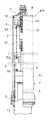
図1に示すように、本実施の形態に係る懸架装置は、アウターチューブT1とこのアウターチューブT1内に出没可能に挿入されるインナーチューブT2とからなり伸縮可能な懸架装置本体Fと、この懸架装置本体F内に収容されて上記懸架装置本体Fを常に伸張方向に附勢する懸架ばねSと、上記懸架装置本体Fの一方側開口部に取り付けられる環状のキャップ部材1と、このキャップ部材1に垂設されるホルダ2と、このホルダ2の軸方向に沿って移動可能で上記懸架ばねSの一方端Saを支持する移動シート3と、上記キャップ部材1内周に軸方向に移動可能に螺合して上記移動シート3を駆動するアジャスタ4とを備える。
As shown in FIG. 1, the suspension device according to the present embodiment includes a suspension device main body F that includes an outer tube T <b> 1 and an inner tube T <b> 2 that can be inserted and retracted into the outer tube T <b> 1. A suspension spring S that is accommodated in the apparatus main body F and constantly urges the suspension apparatus main body F in the extending direction, an
そして、上記アジャスタ4が、上記キャップ部材1内周に螺合する螺子部40と、この螺子部40に連設されるとともに上記螺子部40と逆螺子に設定される逆螺子部41とを備え、上記移動シート3が上記ホルダ2との相対回転を防止されて上記逆螺子部41に螺合する。
The
さらに、本実施の形態に係る懸架装置は、自動二輪車等の鞍乗型車両において前輪を懸架するフロントフォークであり、図2に示すように、前輪9の両側に起立する左右一対の懸架装置部材FL,FRを備える。これらの懸架装置部材FL,FRは、アウターチューブT1とインナーチューブT2とからなる懸架装置本体Fをそれぞれ備え、各懸架装置本体F,F内に懸架ばねSをそれぞれ収容している。
Furthermore, the suspension device according to the present embodiment is a front fork that suspends a front wheel in a straddle-type vehicle such as a motorcycle, and a pair of left and right suspension devices that stand on both sides of the
尚、本実施の形態において、一方の懸架装置部材FRにのみ本発明が具現化されており、この一方の懸架装置部材FRの懸架ばねSによる反力のみを調整することができる。 In the present embodiment, the present invention is embodied only in one suspension device member FR, and only the reaction force by the suspension spring S of this one suspension device member FR can be adjusted.
また、上記各懸架装置本体F,F内には、懸架ばねSと並列に緩衝器Dがそれぞれ収容されている。この緩衝器Dの構成は、周知であるため、詳細に図示しないが、図1に示すように、懸架装置本体F内に起立して作動流体を収容するシリンダ5と、このシリンダ5内に移動可能に挿入されるロッド6とを備えている。
Further, shock absorbers D are accommodated in parallel to the suspension springs S in the suspension device main bodies F and F, respectively. Since the configuration of the shock absorber D is well known, it is not shown in detail. However, as shown in FIG. 1, as shown in FIG. And a
さらに、上記緩衝器Dは、図示しないが、上記ロッド6に保持されて上記シリンダ5の内周面に摺接し上記シリンダ5内を二つの部屋に区画するピストンと、上記二つの部屋を連通する流路と、この流路を通過する作動流体に抵抗を与えるリーフバルブやオリフィス等からなる減衰力発生手段とを備えている。
Further, although not shown, the shock absorber D communicates the two chambers with a piston that is held by the
そして、上記ロッド6は、フロントフォークの伸縮に伴いシリンダ5内を移動するため、図示しないピストンで加圧される一方の部屋の作動流体が上記流路を通過して他方室に移動する。このとき、緩衝器Dは、作動流体が上記流路を通過する際の上記減衰力発生手段の抵抗に起因する減衰力を発生し、フロントフォークの伸縮運動を抑制する。
Since the
以下、一方の懸架装置部材FRにのみ具現化される本発明の各構成部品について詳細に説明する。本実施の形態において、懸架装置本体Fの図1中上側となる一方側開口部に取り付けられる環状のキャップ部材1は、上記懸架装置本体F内周に螺合しており、キャップ部材1と懸架装置本体Fとの間は環状のシール7aで塞がれている。
Hereinafter, each component of the present invention embodied only in one suspension device member FR will be described in detail. In the present embodiment, an
また、図3に示すように、キャップ部材1における懸架装置本体Fの内部側面(図3中下面)には、内周部10と外周部11との間に円環状の溝1aが形成されており、キャップ部材1における中央部12の肉厚が薄くなっている。これにより、キャップ部材1の中央部12から内周部10及び外周部11が懸架装置本体Fの内部側に突出した形状となる。
Further, as shown in FIG. 3, an
さらに、上記キャップ部材1の内周面には、大気側の平滑部1bと、螺子溝が形成される緩衝器側(懸架装置本体Fの内部側)の螺子溝部1cが軸方向に並んで形成されており、この螺子溝部1cにアジャスタ4が移動可能に螺合している。
Further, on the inner peripheral surface of the
上記アジャスタ4は、図3,4に示すように、使用者が操作するための操作部42と、キャップ部材1に螺合する螺子部40と、この螺子部40と逆螺子に設定されるとともに上記螺子部40よりも小径に形成される逆螺子部41とを備えており、これらは大気側から順に同軸に連設される。
As shown in FIGS. 3 and 4, the
また、上記操作部42の螺子部側(図3中下側)には、環状のシール7bが係合しており、アジャスタ4は、このシール7bを介してキャップ部材1の平滑部1bに摺接する。また、上記螺子部40の逆螺子部側(図3中下側)には、ストッパリング8が係合しており、アジャスタ4の大気側(図3中上側)への移動をこのストッパリング8で規制している。
Further, an
もどって、上記キャップ部材1における懸架装置本体Fの内部側に突出した内周部10の外周には、筒状に形成されるホルダ2が螺合しており、キャップ部材1に垂直に設けられている。
Returning, a
上記ホルダ2は、上記キャップ部材1に螺合するナット状の結合部20と、この結合部20の反キャップ部材側に同軸に連設される筒状のホルダ本体21と、このホルダ本体21の反キャップ部材側に同軸に連設されて内径が上記ホルダ本体21の内径よりも小径に形成されるロッド保持部22とからなる。
The
そして、上記ホルダ本体21の側部には、相対向して配置される一対のガイド孔21a,21bが結合部側からロッド保持部側にかけて形成されている。また、ロッド保持部22のホルダ本体側端部22aの内径は、先端側(反ホルダ本体側)と比較して小径に形成されており、この先端側内周にロッド6を螺合したとき、ロッド6が上記ホルダ本体側端部22aに突き当たるようになっている。
A pair of
さらに、本実施の形態において、このロッド保持部22の反キャップ部材側には、ロックナットNが直列に設けられてダブルナット構造とされており、ロッド6の緩み止めをしている。
Further, in the present embodiment, a lock nut N is provided in series on the side of the
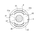
つづいて、上記懸架ばねSの一方端Saを支持する上記移動シート3は、図5に示すように、環板状に形成される円環部30と、この円環部30から直径方向に突出する一対の支持部31,32とからなる。
Subsequently, the
そして、上記移動シート3における円環部30が上記ホルダ本体21の内部に遊嵌されるとともにアジャスタ4の逆螺子部41外周に螺合し、上記両支持部31,32が上記ガイド孔21a,21bからホルダ本体21の外側に突出している。また、上記移動シート3における円環部30の直径が上記ガイド孔21a,21bの幅よりも大きく形成されることから、円環部30がホルダ本体21内に配置された状態に維持される。
The
つまり、上記構成を備えることにより、移動シート3は、円環部30がホルダ本体21内に維持された状態でガイド孔21a,21bに沿って軸方向に移動することができる。しかし、移動シート3がホルダ2に対して回転しようとしても、支持部31,32がホルダ本体21に当接するため、移動シート3とホルダ2との相対回転が阻止される。
That is, by providing the above configuration, the
また、上記移動シート3の図1中下側となる反キャップ部材側面には、筒状のばね受けS1に嵌合するリングS2が当接しており、移動シート3は、このばね受けS1及びリングS2を介して懸架ばねSの一方端Saを支持している。また、この懸架ばねSの他方端Sbは、図1に示すように、上記緩衝器Dのシリンダ側に担持されており、懸架ばねSは、シリンダ5と移動シート3との間に介装されている。
Further, a ring S2 fitted to the cylindrical spring receiver S1 is in contact with the side surface of the
つぎに、本実施の形態に係る懸架装置たるフロントフォークの作用効果について説明する。本実施の形態において、懸架ばねSの一方端Saを支持する移動シート3を駆動するアジャスタ4が、螺子部40と逆螺子部41とを備えるとともに、移動シート3がホルダ2に軸方向に移動可能で、且つ、相対回転できないように上記逆螺子部41に螺合している。
Next, the function and effect of the front fork as the suspension device according to the present embodiment will be described. In the present embodiment, the
したがって、図6に示すように、アジャスタ4が図6中下側となる懸架装置本体Fの内部側に移動するようアジャスタ4を回転すると、このアジャスタ4の回転分移動シート3が逆螺子部41上を図6中下側に移動する。つまり、移動シート3が移動する距離Xは、アジャスタ4の軸方向の移動により移動する距離X1と、アジャスタ4の逆螺子部41上を移動シート3が移動する距離(アジャスタ4の回転により移動シート3が移動する距離)X2の和となる。
Therefore, as shown in FIG. 6, when the
また、アジャスタ4を逆方向に回転した場合には、アジャスタ4及び移動シート3の移動する方向が逆(図6中上側)になるものの、移動シート3の移動する距離は上記と同様である。
Further, when the
つまり、本発明によれば、従来よりもアジャスタ4の移動量に対する移動シート3の移動量が増えるため、移動シート3の移動量を増やしたとしてもアジャスタ4の移動量が増えることを抑制し、アジャスタ4がキャップ部材1から突き出る量を抑え、外観の悪化を抑制することが可能となる。
That is, according to the present invention, since the movement amount of the
また、本実施の形態のように、一対の懸架装置部材FL,FRのうち、一方の懸架装置部材FRの懸架ばねSによる反力のみを調整する場合(以下、片側調整という)、各懸架装置部材FL,FRの各懸架ばねSによる反力をそれぞれ調整する場合(以下、両側調整という)と同様のフロントフォークにおける反力の調整範囲を確保しようとすると、移動シート3の移動量を両側調整の倍にしなければならない。このため、片側調整においては、アジャスタ4の移動量に対する移動シート3の移動量を増やすことが特に有効である。
Moreover, when only the reaction force by the suspension spring S of one suspension device member FR is adjusted (hereinafter referred to as one-side adjustment) among the pair of suspension device members FL and FR as in the present embodiment, each suspension device When the reaction force of each suspension spring S of the members FL and FR is adjusted individually (hereinafter referred to as “both side adjustment”), the same adjustment range of the reaction force in the front fork is secured. Must be doubled. For this reason, in the one-side adjustment, it is particularly effective to increase the movement amount of the
また、本実施の形態のように、片側調整とすることで、他方の懸架装置部材FLにおけるキャップ部材部分の構成を簡易にすることができ、フロントフォークのコストを低減することが可能となる。 In addition, as in the present embodiment, the one-side adjustment can simplify the configuration of the cap member portion of the other suspension device member FL, thereby reducing the cost of the front fork.
また、本実施の形態においては、ホルダ2が筒状に形成されるホルダ本体21と、このホルダ本体21の側部に相対向して形成される一対のガイド孔21a,21bとを備え、移動シート3が環板状に形成される円環部30と、この円環部30から直径方向に突出する一対の支持部31,32とからなり、円環部30がホルダ本体21の内部に遊嵌されるとともに、両支持部31,32がガイド孔21a,21bからホルダ本体21の外側に突出する。
Further, in the present embodiment, the
したがって、移動シート3をホルダ2の軸方向に沿って移動可能にすること、及び、移動シート3とホルダ2との相対回転を阻止することが容易に可能となる。
Therefore, the
また、本実施の形態において、上記キャップ部材1の内周面に、大気側の平滑部1bと、螺子溝が形成される内部側(緩衝器側)の螺子溝部1cが軸方向に並んで形成されており、上記アジャスタ4の螺子部40が上記螺子溝部1cに螺合するとともに、上記アジャスタ4が上記螺子部40の大気側に同軸に配置される操作部42を備え、この操作部42に係合する環状のシール7bを介して上記平滑部1bに摺接する。
Further, in the present embodiment, the air side
したがって、上記シール7bで懸架装置本体F内に収容される作動流体や気体が大気側に漏れることを防ぐことが可能となる。
Therefore, it becomes possible to prevent the working fluid or gas accommodated in the suspension apparatus main body F from leaking to the atmosphere side by the
また、本実施の形態のアジャスタ4において、移動シート3が螺合する逆螺子部41が螺子部40よりも小径に形成されることから、移動シート3が螺子部40に移動することを容易に阻止することが可能となる。
Further, in the
以上、本発明の好ましい実施の形態を詳細に説明したが、特許請求の範囲から逸脱することなく改造、変形及び変更を行うことができることは理解すべきである。 Although preferred embodiments of the present invention have been described in detail above, it should be understood that modifications, variations and changes may be made without departing from the scope of the claims.
例えば、上記実施の形態に係る懸架装置は、自動二輪車等の鞍乗型車両において前輪を懸架するフロントフォークであるが、後輪を懸架するリアクッションユニットであるとしても良く、他の車両用の懸架装置であるとしても良い。 For example, the suspension device according to the above embodiment is a front fork that suspends a front wheel in a straddle-type vehicle such as a motorcycle, but may be a rear cushion unit that suspends a rear wheel. It may be a suspension device.
また、上記実施の形態においては、一方の懸架装置部材FRにのみ本発明を具現化するとしたが、両方の懸架装置部材FL,FRに本発明を具現化するとしても良い。 In the above embodiment, the present invention is embodied only in one suspension device member FR. However, the present invention may be embodied in both suspension device members FL and FR.
また、上記実施の形態のフロントフォークは、アウターチューブT1が車体側に配置され、インナーチューブT2が車輪側に配置される倒立型のフロントフォークであるが、アウターチューブT1が車輪側に配置され、インナーチューブT2が車体側に配置される正立型のフロントフォークであるとしても良い。 Further, the front fork of the above embodiment is an inverted front fork in which the outer tube T1 is disposed on the vehicle body side and the inner tube T2 is disposed on the wheel side, but the outer tube T1 is disposed on the wheel side, The inner tube T2 may be an upright front fork disposed on the vehicle body side.
また、上記実施の形態において、キャップ部材1がアウターチューブT1に取り付けられているが、インナーチューブT2に取り付けられるとしても良い。
Moreover, in the said embodiment, although the
また、懸架装置本体内F内に、如何なる形態の緩衝器Dを収容するとしても良く、一方の懸架装置本体F内にのみ懸架ばねSや緩衝器Dが収容されていても良い。 Further, any type of shock absorber D may be accommodated in the suspension device main body F, and the suspension spring S and the shock absorber D may be accommodated only in one of the suspension device main bodies F.
また、上記実施の形態においては、移動シート3が、リングS2及びばね受けS1を介して懸架ばねSを支持しているが、移動シート3の反キャップ部材側面に懸架ばねSを直接当接させても良い。
In the above embodiment, the
また、ホルダ2,移動シート3,アジャスタ4の形状は上記の限りではなく、移動シート3がアジャスタ4の逆螺子部41に軸方向に移動可能に螺合されるとともに、ホルダ2との相対回転が阻止されていれば良く、適宜形状を選択することが可能である。
The shape of the
また、上記実施の形態においては、ホルダ2がキャップ部材1に螺合されているが、溶接や嵌合等によりホルダ2とキャップ部材1とを結合するとしても良く、また、ホルダ2とキャップ部材1を一体的に形成するとしても良い。
Moreover, in the said embodiment, although the
D 緩衝器
F 懸架装置本体
FL,FR 懸架装置部材
S 懸架ばね
S1 ばね受け
S2 リング
T1 アウターチューブ
T2 インナーチューブ
1,100 キャップ部材
2 ホルダ
3,300 移動シート
4,400 アジャスタ
5 シリンダ
6 ロッド
7a,7b シール
8 ストッパリング
9 前輪
20 結合部
21 ホルダ本体
22 ロッド保持部
21a,21b ガイド孔
30 円環部
31,32 支持部
40 螺子部
41 逆螺子部
42 操作部
D Shock absorber F Suspension device body FL, FR Suspension device member S Suspension spring S1 Spring receiver S2 Ring T1 Outer tube T2 Inner tube 1,100
Claims (4)
上記アジャスタが、上記キャップ部材内周に螺合する螺子部と、この螺子部に連設されるとともに上記螺子部と逆螺子に設定される逆螺子部とを備え、上記移動シートが上記ホルダとの相対回転を防止されて上記逆螺子部に螺合することを特徴とする懸架装置。 A suspension device main body that includes an outer tube and an inner tube that can be inserted into and retracted from the outer tube, and a suspension spring that is housed in the suspension device body and constantly urges the suspension device body in the extension direction. An annular cap member attached to one opening of the suspension device body, a holder suspended from the cap member, and movable along the axial direction of the holder to support one end of the suspension spring A suspension device comprising: a movable seat that is configured to be moved; and an adjuster that is screwed to the inner periphery of the cap member so as to be movable in the axial direction, and that drives the movable seat.
The adjuster includes: a screw portion that is screwed to the inner periphery of the cap member; and a reverse screw portion that is connected to the screw portion and is set to the screw portion and a reverse screw. The suspension device is characterized in that relative rotation is prevented and screwed into the reverse screw portion.
上記移動シートが環板状に形成される円環部と、この円環部から直径方向に突出する一対の支持部とからなり、
上記円環部が上記ホルダ本体の内部に遊嵌されるとともに、上記両支持部が上記ガイド孔から上記ホルダ本体の外側に突出することを特徴とする請求項1に記載の懸架装置。 A holder body in which the holder is formed in a cylindrical shape, and a pair of guide holes formed opposite to the sides of the holder body,
The moving sheet comprises an annular part formed in an annular plate shape, and a pair of support parts projecting in a diameter direction from the annular part,
2. The suspension device according to claim 1, wherein the annular portion is loosely fitted inside the holder main body, and the two support portions protrude from the guide hole to the outside of the holder main body.
上記アジャスタの上記螺子部が上記螺子溝部に螺合するとともに、上記アジャスタが上記螺子部の大気側に同軸に配置される操作部を備え、この操作部に係合する環状のシールを介して上記平滑部に摺接することを特徴とする請求項1または請求項2に記載の緩衝器。 On the inner peripheral surface of the cap member, an air-side smooth portion and an inner-side screw groove portion in which a screw groove is formed are formed side by side in the axial direction.
The screw portion of the adjuster is screwed into the screw groove portion, and the adjuster includes an operation portion that is coaxially disposed on the atmosphere side of the screw portion, and the annular portion is engaged with the operation portion via an annular seal. The shock absorber according to claim 1 or 2, wherein the shock absorber is in sliding contact with the smooth portion.
Priority Applications (1)
| Application Number | Priority Date | Filing Date | Title |
|---|---|---|---|
| JP2011269911A JP2013122256A (en) | 2011-12-09 | 2011-12-09 | Suspension |
Applications Claiming Priority (1)
| Application Number | Priority Date | Filing Date | Title |
|---|---|---|---|
| JP2011269911A JP2013122256A (en) | 2011-12-09 | 2011-12-09 | Suspension |
Publications (1)
| Publication Number | Publication Date |
|---|---|
| JP2013122256A true JP2013122256A (en) | 2013-06-20 |
Family
ID=48774333
Family Applications (1)
| Application Number | Title | Priority Date | Filing Date |
|---|---|---|---|
| JP2011269911A Pending JP2013122256A (en) | 2011-12-09 | 2011-12-09 | Suspension |
Country Status (1)
| Country | Link |
|---|---|
| JP (1) | JP2013122256A (en) |
Cited By (2)
| Publication number | Priority date | Publication date | Assignee | Title |
|---|---|---|---|---|
| JP2016164444A (en) * | 2015-03-06 | 2016-09-08 | 株式会社ショーワ | Suspension device |
| WO2023119372A1 (en) * | 2021-12-20 | 2023-06-29 | Kybモーターサイクルサスペンション株式会社 | Front fork |
-
2011
- 2011-12-09 JP JP2011269911A patent/JP2013122256A/en active Pending
Cited By (2)
| Publication number | Priority date | Publication date | Assignee | Title |
|---|---|---|---|---|
| JP2016164444A (en) * | 2015-03-06 | 2016-09-08 | 株式会社ショーワ | Suspension device |
| WO2023119372A1 (en) * | 2021-12-20 | 2023-06-29 | Kybモーターサイクルサスペンション株式会社 | Front fork |
Similar Documents
| Publication | Publication Date | Title |
|---|---|---|
| JP6731537B2 (en) | Shock absorber | |
| WO2014057897A1 (en) | Suspension device | |
| JP6013958B2 (en) | Suspension device | |
| JP6450135B2 (en) | Diaphragm unit and suspension | |
| WO2013018479A1 (en) | Damper | |
| JP2013122256A (en) | Suspension | |
| JP2020067105A (en) | Buffer | |
| JP6646502B2 (en) | Suspension system | |
| JP2014190404A (en) | Suspension | |
| WO2008087660A1 (en) | Shock absorber for an automobile | |
| JP5481361B2 (en) | Fluid pressure buffer | |
| JP5764021B2 (en) | Shock absorber | |
| JP5486471B2 (en) | Fluid pressure buffer | |
| JP5112985B2 (en) | Rebound spring | |
| JP5806598B2 (en) | Front fork | |
| KR20130043730A (en) | Shock absorber for cars | |
| JP2020084998A (en) | Buffer | |
| JPS6242871Y2 (en) | ||
| JP2005145388A (en) | Vehicle height adjusting mechanism | |
| JP5952695B2 (en) | Suspension device | |
| KR20160046434A (en) | Motor vehicle shock absorber | |
| WO2020100793A1 (en) | Shock absorber | |
| JP2020084999A (en) | Buffer | |
| JP2020085000A (en) | Buffer | |
| JP6039448B2 (en) | Suspension device |