JP2013122144A - Fixture - Google Patents
Fixture Download PDFInfo
- Publication number
- JP2013122144A JP2013122144A JP2011271134A JP2011271134A JP2013122144A JP 2013122144 A JP2013122144 A JP 2013122144A JP 2011271134 A JP2011271134 A JP 2011271134A JP 2011271134 A JP2011271134 A JP 2011271134A JP 2013122144 A JP2013122144 A JP 2013122144A
- Authority
- JP
- Japan
- Prior art keywords
- fixed base
- fixing
- groove
- fixing base
- bolt
- Prior art date
- Legal status (The legal status is an assumption and is not a legal conclusion. Google has not performed a legal analysis and makes no representation as to the accuracy of the status listed.)
- Granted
Links
- 238000009434 installation Methods 0.000 claims description 10
- 238000004519 manufacturing process Methods 0.000 abstract description 6
- 230000002265 prevention Effects 0.000 abstract 1
- 239000000463 material Substances 0.000 description 8
- 229910052751 metal Inorganic materials 0.000 description 6
- 239000002184 metal Substances 0.000 description 6
- 230000004048 modification Effects 0.000 description 4
- 238000012986 modification Methods 0.000 description 4
- 238000001125 extrusion Methods 0.000 description 3
- 238000000034 method Methods 0.000 description 3
- XLYOFNOQVPJJNP-UHFFFAOYSA-N water Substances O XLYOFNOQVPJJNP-UHFFFAOYSA-N 0.000 description 3
- 229910000838 Al alloy Inorganic materials 0.000 description 2
- 238000005452 bending Methods 0.000 description 2
- 230000035515 penetration Effects 0.000 description 2
- 239000011120 plywood Substances 0.000 description 2
- 238000010248 power generation Methods 0.000 description 2
- 239000002023 wood Substances 0.000 description 2
- 230000006835 compression Effects 0.000 description 1
- 238000007906 compression Methods 0.000 description 1
- 239000002245 particle Substances 0.000 description 1
- 239000007787 solid Substances 0.000 description 1
- 229920003002 synthetic resin Polymers 0.000 description 1
- 239000000057 synthetic resin Substances 0.000 description 1
Images


Classifications
-
- Y—GENERAL TAGGING OF NEW TECHNOLOGICAL DEVELOPMENTS; GENERAL TAGGING OF CROSS-SECTIONAL TECHNOLOGIES SPANNING OVER SEVERAL SECTIONS OF THE IPC; TECHNICAL SUBJECTS COVERED BY FORMER USPC CROSS-REFERENCE ART COLLECTIONS [XRACs] AND DIGESTS
- Y02—TECHNOLOGIES OR APPLICATIONS FOR MITIGATION OR ADAPTATION AGAINST CLIMATE CHANGE
- Y02B—CLIMATE CHANGE MITIGATION TECHNOLOGIES RELATED TO BUILDINGS, e.g. HOUSING, HOUSE APPLIANCES OR RELATED END-USER APPLICATIONS
- Y02B10/00—Integration of renewable energy sources in buildings
- Y02B10/10—Photovoltaic [PV]
-
- Y—GENERAL TAGGING OF NEW TECHNOLOGICAL DEVELOPMENTS; GENERAL TAGGING OF CROSS-SECTIONAL TECHNOLOGIES SPANNING OVER SEVERAL SECTIONS OF THE IPC; TECHNICAL SUBJECTS COVERED BY FORMER USPC CROSS-REFERENCE ART COLLECTIONS [XRACs] AND DIGESTS
- Y02—TECHNOLOGIES OR APPLICATIONS FOR MITIGATION OR ADAPTATION AGAINST CLIMATE CHANGE
- Y02E—REDUCTION OF GREENHOUSE GAS [GHG] EMISSIONS, RELATED TO ENERGY GENERATION, TRANSMISSION OR DISTRIBUTION
- Y02E10/00—Energy generation through renewable energy sources
- Y02E10/50—Photovoltaic [PV] energy
Abstract
Description
本発明は、屋根に設備を固定する固定具に関する。 The present invention relates to a fixture for fixing equipment to a roof.
太陽光発電、太陽熱利用温水器、空気調和設備の室外機などの設備を建造物の屋根上に設置する場合、これら設備を固定する固定具は、屋根上に設置する設備の質量や設置する地域の風圧、地震などに耐えうる強度の確保が必要である。これらの設備の固定は、設備を固定するための固定具を予め屋根上に固定し、その固定具上に設備を固定する方法が一般的である。固定具は十分な固定強度を確保するために、建造物の野地板を介して垂木など建造物の構造体にネジ、釘、またはボルト・ナットで固定される。 When installing facilities such as solar power generation, solar water heaters, and air conditioner outdoor units on the roof of the building, the fixtures to fix these facilities are the mass of the facility installed on the roof and the area where it is installed. It is necessary to secure sufficient strength to withstand wind pressure and earthquakes. In general, these facilities are fixed by fixing a fixture for fixing the facility on the roof in advance and fixing the facility on the fixture. In order to secure a sufficient fixing strength, the fixing tool is fixed to a structure of the building such as a rafter through a building base plate with screws, nails, or bolts and nuts.
例えば特許文献1には、構造体を屋根上に取り付けるための支持装置として、スライド孔が形成された主板、主板の両側で同じ側に折り曲げられた各側板、および各側板の一辺で外側に折り曲げられた固定台と、固体台のスライド孔に沿って移動自在な移動部と、移動部に接続される連結部本体からなる構造が示されている。固定台には、複数の穿孔および、長孔が形成されており、野地板を介して固定台を垂木に強固に固定できるとともに、スライド孔に沿って連結部位置の調節を可能としている。 For example, in Patent Document 1, as a support device for mounting a structure on a roof, a main plate in which a slide hole is formed, each side plate bent to the same side on both sides of the main plate, and one side of each side plate is bent outward. A structure comprising a fixed base, a moving part movable along a slide hole of a solid base, and a connecting part main body connected to the moving part is shown. A plurality of perforations and long holes are formed in the fixing base, and the fixing base can be firmly fixed to the rafters via the base plate, and the position of the connecting portion can be adjusted along the slide hole.
しかしながら、上記の支持装置では、固定台に形成されたスライド孔にて、主板の端面が部分的に薄板となるため、風荷重や積雪荷重に対する耐荷重性能が、低下してしまう場合がある。それを回避するためには、例えば、スライド孔の開口長を小さくする方法があるが、この場合には連結部の位置調整可能な範囲を狭めてしまう。 However, in the above support device, the end face of the main plate is partially thin at the slide hole formed in the fixed base, and thus the load bearing performance against wind load and snow load may be reduced. In order to avoid this, for example, there is a method of reducing the opening length of the slide hole.
また固定台を2本の垂木に強固に固定するために、垂木に跨るように固定台を配置する場合には、少なくとも垂木間隔以上に固定台を延長する必要があるが、それに伴い、特に板材の曲げ加工にかかる製造コストが増大する。 Further, in order to firmly fix the fixing base to the two rafters, when the fixing base is arranged so as to straddle the rafters, it is necessary to extend the fixing base at least more than the rafter interval. The manufacturing cost for the bending process increases.
本発明は、上記に鑑みてなされたものであって、建造物の屋根上に設置される設備の位置調整の範囲を確保しつつ、固定強度および耐荷重性能の確保が図れ、製造コストの抑制も図ることができる固定具を得ることを目的とする。 The present invention has been made in view of the above, and while securing the range of position adjustment of equipment installed on the roof of a building, securing of fixing strength and load bearing performance can be ensured, and manufacturing cost can be suppressed. Another object is to obtain a fixture that can also be used.
上述した課題を解決し、目的を達成するために、本発明は、屋根に対して設備を固定させる固定具であって、平面視において略長方形形状を呈し、屋根に固定される固定基部と、固定基部の長手方向と略平行に延びるように固定基部上に立設されて、ボルトの頭部が嵌まるとともに固定基部の長手方向略全域にわたって形成された溝を構成する壁部と、壁部のうち固定基部の反対側の略全域に設けられて、溝から軸部が突出するように溝に嵌められたボルトが、軸部方向に抜け落ちるのを防止する抜け止め部と、溝に嵌められたボルトの軸部を貫通させる貫通孔が形成されるとともに、設備と固定基部とを連結させる連結部と、を備えることを特徴とする。 In order to solve the above-described problems and achieve the object, the present invention is a fixture for fixing equipment to a roof, has a substantially rectangular shape in plan view, and a fixed base fixed to the roof; A wall portion that is erected on the fixed base portion so as to extend substantially parallel to the longitudinal direction of the fixed base portion, and that forms a groove that fits the head portion of the bolt and is formed over substantially the entire longitudinal direction of the fixed base portion; A bolt that is provided in substantially the entire area on the opposite side of the fixed base and is fitted in the groove so as to prevent the bolt fitted in the groove so that the shaft protrudes from the groove, and is fitted in the groove. A through hole that penetrates the shaft portion of the bolt and a connecting portion that connects the facility and the fixed base.
本発明によれば、建造物の屋根上に設置される設備の位置調整の範囲を確保しつつ、固定強度および耐荷重性能の確保が図れるとともに、固定基部および壁部の長手方向への断面形状を略同一とすることで、押出し方式を用いて製造コストの抑制を図ることができるという効果を奏する。 ADVANTAGE OF THE INVENTION According to this invention, while ensuring the range of the position adjustment of the installation installed on the roof of a building, securing of fixed strength and load-bearing performance can be aimed at, and the cross-sectional shape to the longitudinal direction of a fixed base and a wall part By making these substantially the same, the production cost can be suppressed by using the extrusion method.
以下に、本発明の実施の形態にかかる固定具を図面に基づいて詳細に説明する。なお、この実施の形態によりこの発明が限定されるものではない。 Below, the fixture concerning embodiment of this invention is demonstrated in detail based on drawing. Note that the present invention is not limited to the embodiments.
実施の形態1.
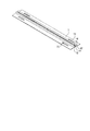
図1は、本発明の実施の形態1にかかる固定具の概略構成を示す外観斜視図である。図2は、図1に示す固定具の側面図である。図3は、固定具が取り付けられる屋根構造を示す斜視図である。図4は、図3に示す屋根構造に取り付けられた固定具を示す斜視図である。
Embodiment 1 FIG.
FIG. 1 is an external perspective view showing a schematic configuration of the fixture according to the first embodiment of the present invention. FIG. 2 is a side view of the fixture shown in FIG. FIG. 3 is a perspective view showing a roof structure to which a fixture is attached. FIG. 4 is a perspective view showing a fixture attached to the roof structure shown in FIG.
実施の形態1にかかる固定具50は、屋根構造に固定され、この固定具50を介して太陽光発電、太陽熱利用温水器、空気調和設備の室外機などの設備(図示を省略)が屋根上に設置される。なお、設備が設置される屋根構造は、例えば、図3に示すように、垂木2、桟木3、野地板4、ルーフィング5、屋根材6を有して構成される。
The
固定具50は、図1等に示すように、固定台(固定基部)7、固定用ボルト(固定台固定手段)8、連結部9、連結用ボルト(連結部固定手段)10を備える。図5は、固定具50が備える固定台7の外観斜視図である。図6−1は、固定具50が備える固定台7の平面図である。図6−2は、固定具50が備える固定台7の正面図である。図6−3は、固定具50が備える固定台7の側面図である。固定台7は、平面視において略直方体形状を呈している。固定台7は、アルミニウム合金などの金属で構成された板部材である。
As shown in FIG. 1 and the like, the
固定台7には、少なくとも1か所以上に長孔73が形成されている。固定台7は、長孔73を介して固定台固定手段としての固定用ボルト8によって屋根構造に固定される。例えば、野地板4や垂木2に形成された下穴に対して、長孔73を貫通させた固定用ボルト8がねじ込まれることで、固定台7が屋根構造に固定される。なお、固定台固定手段は、ネジ、釘等の他の固定手段であっても構わない。
A
固定台7には、その上面に対して長手方向の略全域にわたって壁部12が立設されている。壁部12は、互いに対向するように1組設けられ、壁部12同士の間が、連結部固定手段としての連結用ボルト10の頭部10aが嵌まる溝13を構成する。固定台7の一部が溝13の底面を構成する。すなわち、壁部12同士は、固定台7の一部で連結された構成となる。
A
溝13は、頭部10aの外径よりも若干大きい溝幅で形成されている。例えば、連結用ボルト10の頭部10aと溝13との間には、0.1〜1mm程度のわずかなクリアランスが設けられている。そのため、連結用ボルト10は、溝13に嵌められた状態で、固定台7の長手方向に沿って自在に移動可能となっている。
The
なお、溝13(壁部12)は、連結用ボルト10の頭部10aが嵌まった状態で、連結用ボルトの軸部10bが突出する高さに形成されている。また、壁部12は、固定台7の短手方向に対して略中央部分に形成されているが、短手方向の一方側に片寄せられて形成されていても構わない。
The groove 13 (wall portion 12) is formed at a height at which the
壁部12のうち固定台7の反対側の略全域には、溝13に嵌まったが軸部10b方向に抜け落ちるのを防ぐ抜け止め部14が設けられている。具体的には、抜け止め部14は、溝13の溝幅を、連結用ボルト10の軸部10bの外径よりも若干大きくなる程度の溝幅まで狭めるように形成される。これにより、連結用ボルト10の頭部10aが抜け止め部14に引っ掛かって、軸部10b方向に抜け落ちるのを防ぐことができる。固定台7は、上述したような構成により、長手方向に略同一断面を有することとなる。
A retaining
連結部9は、板厚1〜6mm程度の金属板を折り曲げた構造、または、同一断面を有する押出し方式にて得られた構造であり、アルミニウム合金等の金属で構成される。連結部9は、図1や図2に示すように、貫通板部93、つなぎ部95、設備取付部91を有して構成される。
The connecting
貫通板部93は、板状形状を呈しており、溝13に嵌められた連結用ボルト10の軸部10bを貫通させるための貫通孔94が形成されている。貫通孔94は、少なくとも1箇所以上形成されている。貫通板部93の貫通孔94に貫通された軸部10bにナット11がねじ込まれることで、連結部9は、固定台7に固定される。貫通板部93は、連結用ボルト10とナット11とで固定されることで、固定台7と略平行な状態となる。
The through
つなぎ部95は、貫通板部93の端部に対して、固定台7から離れる方向に立設されている。設備取付部91は、つなぎ部95の上端から延びるように設けられている。すなわち、貫通板部93と設備取付部91とは、つなぎ部95を介して連結されている。また、つなぎ部95が貫通板部93に対して立設されているので、貫通板部93と設備取付部91との間には段差が設けられることとなる。
The connecting
設備取付部91は、図2に示すように、断面コ字形状を呈している。設備取付部91には、屋根上に設置される設備を取り付けるための取付孔92が形成されている。屋根上に設置される設備は、取付孔92を利用して、ボルト・ナット等によって、固定具50に取り付けられる。
The
次に、固定具50の屋根構造への取付方法を説明する。まず、屋根構造から屋根材6の一部を取り外し、ルーフィング5または野地板4を露出させる。屋根材6は木ネジや釘で桟木3に固定されている場合もある。
Next, a method for attaching the
長孔73が垂木2の位置に合うように固定台7を仮置きする。そして、少なくとも壁部12を挟んだ両側の各1か所ずつの長孔73で、固定用ボルト8によって、野地板4を介した状態で固定台7と垂木2とを固定させる。野地板4は、例えば厚さ9mm以上の木製の構造用合板やパーチクルボードなどの圧縮合板である。垂木2は、例えば高さ20mm以上の木材、もしくは金属である。
The fixing
ここで、固定台7の上面からの壁部12の上面まで高さは、固定用ボルト8の頭部8aの高さよりも高くなっている。これにより、壁部12の上面に取り付けられる連結部9などの部品と固定用ボルト8の頭部8aとの干渉を回避することができる。
Here, the height from the upper surface of the fixing
固定台7の底面から壁部12の上面までの高さは、15mm以下であることが望ましい。例えば、瓦屋根材の下に固定台7を設置する場合、高さが高いと固定台7と瓦とが干渉し、軒側の瓦と棟側の瓦の隙間が広がり、防水機能を低下させるおそれがある。よって、防水性を確保するためには、固定台7の底面から壁部12の上面までの高さを15mm以下とすることが、望ましい。
The height from the bottom surface of the fixed
図7−1は、固定台7の溝13に連結用ボルト10を嵌め込んだ状態を示す斜視図である。図7−2は、固定台7の溝13に連結用ボルト10を嵌め込んだ状態を示す断面図である。次に、図7−1や図7−2に示すように、連結用ボルト10を、固定台7の溝13に端面から挿入する。連結用ボルト10は、金属製のボルトである。そして、溝13に沿って連結用ボルト10を所望の位置まで移動させる。なお、固定台7を固定用ボルト8によって屋根構造に固定する前に、連結用ボルト10を溝13に仮挿入しておいてもよい。
FIG. 7A is a perspective view illustrating a state in which the connecting
次に、連結用ボルト10を連結部9の貫通孔94に挿入し、連結部9の貫通板部93と固定台7の壁部12とを合わせて、ナット11によって仮固定する。ナット11によって仮固定された状態では、固定台7の長手方向に連結部9を容易に移動可能である。
Next, the connecting
なお、連結部9の貫通板部93に複数の貫通孔94が形成されていれば、複数の連結用ボルト10を用いて連結部9を固定することができる。この場合、連結部9は複数点にて固定されることで、回転が防止されて、位置精度の向上を図ることができる。
In addition, if the some through-
次に、連結部9の位置を屋根材6に合うように調整し、連結用ボルト10およびナット11を本締めする。そして、屋根上に設置される設備の設備取付部91への取り付けや、屋根構造の復旧等が行われる。
Next, the position of the connecting
以上説明した固定具50によれば、設備取付部91に取り付けられた設備を通じて、固定台7に風荷重や積雪荷重が加わっても、固定台7が垂木2に固定されているため、十分な耐荷重性能を確保しやすく、構造物の破損や、繰り返し応力による固定台7の野地板4からの剥離に起因する雨漏りの発生を抑えることができる。
According to the
また、固定台7が長手方向に略同一断面を有するので、押出し方式によって固定台7を製造することができるため、曲げ加工によって製造する場合に比べて、製造コストの抑制を図ることができる。
Moreover, since the fixing
また、板状形状を呈する固定台7上に壁部12が形成されて、連結用ボルト10の頭部10aが嵌まる溝13が形成されるので、壁部12を含めて固定台7において曲げ部分を少なくすることができ、全体的な強度の向上を図ることができる。また、溝13が固定台7の長手方向略全域にわたって形成されるので、連結部9の位置調整の幅を十分に確保しやすくなる。
Further, the
また、連結部9において、貫通板部93と設備取付部91との間に段差が設けられているので、図4に示すように、固定台7を野地板4に固定しつつ、設備取付部91は屋根材61の上に配置させることができる。
Moreover, in the
なお、固定台7や連結部9が金属で構成されていると説明したが、これに限られず、十分な強度を得られれば、合成樹脂等の他の材料で構成されていても構わない。
In addition, although it demonstrated that the fixing
図8−1は、固定台7の変形例を示す外観斜視図である。図8−2は、図8−1に示す固定台7の平面図である。図8−3は、図8−1に示す固定台7の正面図である。図8−4は、図8−1に示す固定台7の側面図である。本変形例にかかる固定台7では、平面視における長辺に、高さ方向(壁部12の立設方向)に立設された薄板部75が設けられている。固定台7と薄板部75とがなす角度は、略90度となっている。
FIG. 8A is an external perspective view showing a modified example of the fixing
薄板部75を設けることで、固定台7の高さ方向に対する断面係数が大きくなるため、耐荷重性能がさらに向上し、より強風地域への設置などが可能となる。なお、薄板部75の高さは、壁部12の立設高さよりも低くなっており、連結部9との干渉が回避される。
By providing the
図9は、固定台7の他の変形例を示す側面図である。本変形例では、薄板部75と固定台7とがなす角度が90度より大きくなっている。薄板部75と固定台7とがなす角度を90度より大きくすることで、棟側からルーフィング5または野地板4(図3も参照)上を流れてくる雨水が、壁部12と薄板部75との隙間への浸水を抑えることができ、より一層の防水性の向上を図ることができる。
FIG. 9 is a side view showing another modification of the fixing
以上のように、本発明にかかる固定具は、設備の取り付けに有用であり、特に、屋根上に設置される設備の取り付けに適している。 As described above, the fixture according to the present invention is useful for installation of equipment, and is particularly suitable for installation of equipment installed on a roof.
2 垂木
3 桟木
4 野地板
5 ルーフィング
6 屋根材
7 固定台(固定基部)
8 固定用ボルト(固定台固定手段)
8a 頭部
9 連結部
10 連結用ボルト(連結部固定手段)
10a 頭部
10b 軸部
11 ナット
12 壁部
13 溝
14 抜け止め部
50 固定具
73 長孔
75 薄板部
91 設備取付部
92 取付孔
93 貫通板部
94 貫通孔
95 つなぎ部
2 rafters 3 piers 4 field boards 5
8 Fixing bolt (fixing base fixing means)
DESCRIPTION OF
Claims (6)
平面視において略長方形形状を呈し、前記屋根に固定される固定基部と、
前記固定基部の長手方向と略平行に延びるように前記固定基部上に立設されて、ボルトの頭部が嵌まるとともに前記固定基部の長手方向略全域にわたって形成された溝を構成する壁部と、
前記壁部のうち前記固定基部の反対側の略全域に設けられて、前記溝から軸部が突出するように前記溝に嵌められた前記ボルトが、前記軸部方向に抜け落ちるのを防止する抜け止め部と、
前記溝に嵌められた前記ボルトの軸部を貫通させる貫通孔が形成されるとともに、前記設備と前記固定基部とを連結させる連結部と、を備えることを特徴とする固定具。 A fixture for fixing equipment to the roof,
A substantially rectangular shape in plan view, and a fixed base fixed to the roof;
A wall portion that is erected on the fixed base portion so as to extend substantially parallel to the longitudinal direction of the fixed base portion, and that forms a groove that fits a bolt head and is formed over substantially the entire longitudinal direction of the fixed base portion; ,
The wall portion is provided in substantially the entire region on the opposite side of the fixed base portion, and the bolt fitted in the groove so that the shaft portion protrudes from the groove prevents the bolt from falling off in the shaft portion direction. A stop,
A fixing tool comprising: a through hole that passes through the shaft portion of the bolt fitted in the groove; and a connecting portion that connects the facility and the fixed base.
Priority Applications (1)
| Application Number | Priority Date | Filing Date | Title |
|---|---|---|---|
| JP2011271134A JP5734171B2 (en) | 2011-12-12 | 2011-12-12 | Fixture |
Applications Claiming Priority (1)
| Application Number | Priority Date | Filing Date | Title |
|---|---|---|---|
| JP2011271134A JP5734171B2 (en) | 2011-12-12 | 2011-12-12 | Fixture |
Publications (2)
| Publication Number | Publication Date |
|---|---|
| JP2013122144A true JP2013122144A (en) | 2013-06-20 |
| JP5734171B2 JP5734171B2 (en) | 2015-06-10 |
Family
ID=48774264
Family Applications (1)
| Application Number | Title | Priority Date | Filing Date |
|---|---|---|---|
| JP2011271134A Active JP5734171B2 (en) | 2011-12-12 | 2011-12-12 | Fixture |
Country Status (1)
| Country | Link |
|---|---|
| JP (1) | JP5734171B2 (en) |
Cited By (1)
| Publication number | Priority date | Publication date | Assignee | Title |
|---|---|---|---|---|
| US10525406B2 (en) | 2017-05-30 | 2020-01-07 | Saudi Arabian Oil Company | Polymer blended membranes for sour gas separation |
Citations (4)
| Publication number | Priority date | Publication date | Assignee | Title |
|---|---|---|---|---|
| JPH0667659U (en) * | 1993-03-08 | 1994-09-22 | 東日本ハウス株式会社 | Solar cell plate mounting support bracket |
| JP2001303724A (en) * | 2000-04-20 | 2001-10-31 | Matsushita Electric Works Ltd | Solar cell module fitting structure |
| JP2004324181A (en) * | 2003-04-23 | 2004-11-18 | Sanyo Electric Co Ltd | Solar battery device fixed to roof |
| JP2010203165A (en) * | 2009-03-04 | 2010-09-16 | Sharp Corp | Structure support tool and solar battery module system using the same |
-
2011
- 2011-12-12 JP JP2011271134A patent/JP5734171B2/en active Active
Patent Citations (4)
| Publication number | Priority date | Publication date | Assignee | Title |
|---|---|---|---|---|
| JPH0667659U (en) * | 1993-03-08 | 1994-09-22 | 東日本ハウス株式会社 | Solar cell plate mounting support bracket |
| JP2001303724A (en) * | 2000-04-20 | 2001-10-31 | Matsushita Electric Works Ltd | Solar cell module fitting structure |
| JP2004324181A (en) * | 2003-04-23 | 2004-11-18 | Sanyo Electric Co Ltd | Solar battery device fixed to roof |
| JP2010203165A (en) * | 2009-03-04 | 2010-09-16 | Sharp Corp | Structure support tool and solar battery module system using the same |
Cited By (2)
| Publication number | Priority date | Publication date | Assignee | Title |
|---|---|---|---|---|
| US10525406B2 (en) | 2017-05-30 | 2020-01-07 | Saudi Arabian Oil Company | Polymer blended membranes for sour gas separation |
| US11311837B2 (en) | 2017-05-30 | 2022-04-26 | Saudi Arabian Oil Company | Polymer blended membranes for sour gas separation |
Also Published As
| Publication number | Publication date |
|---|---|
| JP5734171B2 (en) | 2015-06-10 |
Similar Documents
| Publication | Publication Date | Title |
|---|---|---|
| US10211775B1 (en) | Rail-less roof mounting system | |
| JP5705380B2 (en) | Solar cell module fixing structure | |
| KR101390571B1 (en) | PV module mounting and support assembly and mounting method | |
| JP2010261257A (en) | Structure for fixing solar cell module | |
| JP2010242367A (en) | Mounting structure of solar battery panel | |
| JPWO2011132735A1 (en) | Mounting method for mounting | |
| US20120211252A1 (en) | Solar Panel Racking System with Integrated Grounding Bar Rail | |
| JP4653578B2 (en) | Building member mounting hardware, building member mounting structure, and building member mounting method | |
| JP5734171B2 (en) | Fixture | |
| JP2017172222A (en) | Fitting structure of fixture | |
| JP5666325B2 (en) | Roof fixing device | |
| JP3162248U (en) | Roof mount support bracket | |
| US20130003274A1 (en) | Solar Panel Racking System With Integrated Grounding Bar Rail | |
| JP2010144440A (en) | Fixing structure of attachment | |
| JP5430544B2 (en) | Auxiliary rafter fixing bracket and equipment fixing device | |
| JP5686771B2 (en) | Solar cell module fixing structure and solar cell module fixing method | |
| JP5714873B2 (en) | Mounting member | |
| JP5648995B2 (en) | Mounting structure of support frame and exterior structure | |
| JP5736157B2 (en) | Fixed base | |
| JP2011122402A (en) | Planar supporting tile for solar panel, and method for installing solar panel using the same | |
| JP5968115B2 (en) | Equipment fixing device | |
| JP3202583U (en) | Support structure for photovoltaic panels | |
| JP5836199B2 (en) | Support bracket | |
| JP2017145607A (en) | Strut mounting structure of wooden flat roof | |
| JP3179995U (en) | Solar panel mounting anchor |
Legal Events
| Date | Code | Title | Description |
|---|---|---|---|
| A977 | Report on retrieval |
Free format text: JAPANESE INTERMEDIATE CODE: A971007 Effective date: 20131031 |
|
| A131 | Notification of reasons for refusal |
Free format text: JAPANESE INTERMEDIATE CODE: A131 Effective date: 20131112 |
|
| A521 | Request for written amendment filed |
Free format text: JAPANESE INTERMEDIATE CODE: A523 Effective date: 20140108 |
|
| A131 | Notification of reasons for refusal |
Free format text: JAPANESE INTERMEDIATE CODE: A131 Effective date: 20140902 |
|
| TRDD | Decision of grant or rejection written | ||
| A01 | Written decision to grant a patent or to grant a registration (utility model) |
Free format text: JAPANESE INTERMEDIATE CODE: A01 Effective date: 20150317 |
|
| A61 | First payment of annual fees (during grant procedure) |
Free format text: JAPANESE INTERMEDIATE CODE: A61 Effective date: 20150414 |
|
| R150 | Certificate of patent or registration of utility model |
Ref document number: 5734171 Country of ref document: JP Free format text: JAPANESE INTERMEDIATE CODE: R150 |
|
| R250 | Receipt of annual fees |
Free format text: JAPANESE INTERMEDIATE CODE: R250 |
|
| R250 | Receipt of annual fees |
Free format text: JAPANESE INTERMEDIATE CODE: R250 |
|
| R250 | Receipt of annual fees |
Free format text: JAPANESE INTERMEDIATE CODE: R250 |
|
| S111 | Request for change of ownership or part of ownership |
Free format text: JAPANESE INTERMEDIATE CODE: R313113 |
|
| R350 | Written notification of registration of transfer |
Free format text: JAPANESE INTERMEDIATE CODE: R350 |
|
| RD02 | Notification of acceptance of power of attorney |
Free format text: JAPANESE INTERMEDIATE CODE: R3D02 |
|
| R250 | Receipt of annual fees |
Free format text: JAPANESE INTERMEDIATE CODE: R250 |
|
| R250 | Receipt of annual fees |
Free format text: JAPANESE INTERMEDIATE CODE: R250 |