JP2013121032A - Image processing apparatus and method - Google Patents
Image processing apparatus and method Download PDFInfo
- Publication number
- JP2013121032A JP2013121032A JP2011267561A JP2011267561A JP2013121032A JP 2013121032 A JP2013121032 A JP 2013121032A JP 2011267561 A JP2011267561 A JP 2011267561A JP 2011267561 A JP2011267561 A JP 2011267561A JP 2013121032 A JP2013121032 A JP 2013121032A
- Authority
- JP
- Japan
- Prior art keywords
- partition
- unit
- data
- body partition
- footer
- Prior art date
- Legal status (The legal status is an assumption and is not a legal conclusion. Google has not performed a legal analysis and makes no representation as to the accuracy of the status listed.)
- Abandoned
Links
- 238000012545 processing Methods 0.000 title claims abstract description 171
- 238000000034 method Methods 0.000 title description 264
- 238000005192 partition Methods 0.000 claims abstract description 707
- 230000010354 integration Effects 0.000 claims abstract description 25
- 238000000926 separation method Methods 0.000 claims description 19
- 239000000284 extract Substances 0.000 claims description 16
- 238000003672 processing method Methods 0.000 claims description 11
- 238000000638 solvent extraction Methods 0.000 claims description 2
- 230000005540 biological transmission Effects 0.000 abstract description 34
- 230000008569 process Effects 0.000 description 232
- 238000004458 analytical method Methods 0.000 description 52
- 230000015572 biosynthetic process Effects 0.000 description 34
- 238000003786 synthesis reaction Methods 0.000 description 33
- 238000001914 filtration Methods 0.000 description 31
- 238000013139 quantization Methods 0.000 description 18
- 238000010586 diagram Methods 0.000 description 16
- 230000009466 transformation Effects 0.000 description 16
- 238000004364 calculation method Methods 0.000 description 15
- 238000004519 manufacturing process Methods 0.000 description 7
- 238000001514 detection method Methods 0.000 description 6
- 238000000354 decomposition reaction Methods 0.000 description 5
- 230000008707 rearrangement Effects 0.000 description 4
- 230000009467 reduction Effects 0.000 description 4
- 238000004891 communication Methods 0.000 description 3
- 230000006835 compression Effects 0.000 description 3
- 238000007906 compression Methods 0.000 description 3
- 230000001934 delay Effects 0.000 description 3
- 238000005516 engineering process Methods 0.000 description 3
- 239000000463 material Substances 0.000 description 3
- 239000004065 semiconductor Substances 0.000 description 3
- 101100162203 Aspergillus parasiticus (strain ATCC 56775 / NRRL 5862 / SRRC 143 / SU-1) aflG gene Proteins 0.000 description 2
- 238000006243 chemical reaction Methods 0.000 description 2
- 239000000470 constituent Substances 0.000 description 2
- 239000013256 coordination polymer Substances 0.000 description 2
- 230000003287 optical effect Effects 0.000 description 2
- 238000004590 computer program Methods 0.000 description 1
- 230000006872 improvement Effects 0.000 description 1
- 230000010365 information processing Effects 0.000 description 1
- 239000004973 liquid crystal related substance Substances 0.000 description 1
- 238000013507 mapping Methods 0.000 description 1
- 238000012986 modification Methods 0.000 description 1
- 230000004048 modification Effects 0.000 description 1
- 238000012856 packing Methods 0.000 description 1
- 230000004044 response Effects 0.000 description 1
- 239000007787 solid Substances 0.000 description 1
- 230000002194 synthesizing effect Effects 0.000 description 1
- 230000001131 transforming effect Effects 0.000 description 1
Images


Classifications
-
- G—PHYSICS
- G06—COMPUTING; CALCULATING OR COUNTING
- G06T—IMAGE DATA PROCESSING OR GENERATION, IN GENERAL
- G06T9/00—Image coding
-
- H—ELECTRICITY
- H04—ELECTRIC COMMUNICATION TECHNIQUE
- H04N—PICTORIAL COMMUNICATION, e.g. TELEVISION
- H04N19/00—Methods or arrangements for coding, decoding, compressing or decompressing digital video signals
- H04N19/60—Methods or arrangements for coding, decoding, compressing or decompressing digital video signals using transform coding
- H04N19/63—Methods or arrangements for coding, decoding, compressing or decompressing digital video signals using transform coding using sub-band based transform, e.g. wavelets
-
- H—ELECTRICITY
- H04—ELECTRIC COMMUNICATION TECHNIQUE
- H04N—PICTORIAL COMMUNICATION, e.g. TELEVISION
- H04N19/00—Methods or arrangements for coding, decoding, compressing or decompressing digital video signals
- H04N19/85—Methods or arrangements for coding, decoding, compressing or decompressing digital video signals using pre-processing or post-processing specially adapted for video compression
- H04N19/88—Methods or arrangements for coding, decoding, compressing or decompressing digital video signals using pre-processing or post-processing specially adapted for video compression involving rearrangement of data among different coding units, e.g. shuffling, interleaving, scrambling or permutation of pixel data or permutation of transform coefficient data among different blocks
-
- G—PHYSICS
- G06—COMPUTING; CALCULATING OR COUNTING
- G06T—IMAGE DATA PROCESSING OR GENERATION, IN GENERAL
- G06T2207/00—Indexing scheme for image analysis or image enhancement
- G06T2207/20—Special algorithmic details
- G06T2207/20048—Transform domain processing
- G06T2207/20064—Wavelet transform [DWT]
Landscapes
- Engineering & Computer Science (AREA)
- Multimedia (AREA)
- Signal Processing (AREA)
- Physics & Mathematics (AREA)
- General Physics & Mathematics (AREA)
- Theoretical Computer Science (AREA)
- Compression Or Coding Systems Of Tv Signals (AREA)
- Compression Of Band Width Or Redundancy In Fax (AREA)
Abstract
Description
本開示は、画像処理装置および方法に関し、特に、画像や音声等のコンテンツファイル伝送の低遅延化を実現させることができるようにした画像処理装置および方法に関する。 The present disclosure relates to an image processing apparatus and method, and more particularly, to an image processing apparatus and method capable of realizing a low delay in transmission of content files such as images and sounds.
従来、画像や音声等の素材をファイル化して伝送するためのファイルフォーマットの標準規格にMXF(Material Exchange Format)があった(例えば、非特許文献1乃至4参照)。非圧縮の映像データや音声データ、または、JPEGやMPEG等の任意の符号化方式で符号化された映像データや音声データは、メタデータとともに、MXFによってファイル化され(梱包され)、伝送される。このようにすることにより、MXF規格に準拠したファイルを授受可能な機器間でのデータ伝送が可能になる。したがって、符号化技術に依存しない、自由度の高い、データ伝送を実現することができ、より多様な機器間で容易にコンテンツデータを伝送することができるようになる。
Conventionally, there has been MXF (Material Exchange Format) as a file format standard for transmitting a material such as an image or sound as a file (for example, see Non-Patent
ところで、画像の符号化方式として、画像をより高速に符号化および復号することができる方法が提案された(例えば、非特許文献5参照)。画像データを伝送するにあたって、画像データを符号化することにより情報量を低減させることができるが、その際、この符号化方式を用いることにより、データ伝送の低遅延化を実現することができる。つまり、画像データを取得してから、符号化し、伝送し、復号し、得られた復号画像を再生したり、復号画像データを記録したりするまでの遅延時間がより低減される。 By the way, as an image encoding method, a method capable of encoding and decoding an image at higher speed has been proposed (for example, see Non-Patent Document 5). In transmitting image data, the amount of information can be reduced by encoding the image data. At this time, by using this encoding method, it is possible to realize a low delay in data transmission. That is, the delay time from obtaining the image data to encoding, transmitting, decoding, reproducing the obtained decoded image or recording the decoded image data is further reduced.
しかしながら、従来のMXF規格の場合、非特許文献5に記載のような低遅延な符号化方式については考慮されておらず、より低遅延なデータ伝送を実現することが困難であった。 However, in the case of the conventional MXF standard, the low-delay encoding method as described in Non-Patent Document 5 is not considered, and it has been difficult to realize data transmission with a lower delay.
本開示は、このような状況に鑑みてなされたものであり、画像や音声等のデータ伝送の、高自由度化および低遅延化を実現することを目的とする。 The present disclosure has been made in view of such a situation, and an object thereof is to realize a high degree of freedom and a low delay in data transmission of images and sounds.
本開示の一側面は、画像データが、画像を複数に分割するラインブロック毎に符号化された符号化データを格納する、所定のフォーマットのファイルのボディパーティションを、1ラインブロック分の符号化データ毎に生成するボディパーティション生成部と、前記ボディパーティション生成部により生成された前記ボディパーティション、ヘッダ情報を含むヘッダパーティション、およびフッタ情報を含むフッタパーティションを統合することにより、前記ファイルを生成するパーティション統合部とを備える画像処理装置である。 One aspect of the present disclosure is that image data stores encoded data that is encoded for each line block that divides an image into a plurality of lines. A body partition of a file in a predetermined format is encoded data for one line block. Partition integration for generating the file by integrating the body partition generation unit generated every time, the body partition generated by the body partition generation unit, the header partition including header information, and the footer partition including footer information An image processing apparatus.
前記ボディパーティション生成部は、1つの前記ファイルに1ラインブロック分の前記符号化データを格納させるように、1つの前記ファイルに対して、前記符号化データを含むボディパーティションを1つ生成することができる。 The body partition generation unit may generate one body partition including the encoded data for one file so that the encoded data for one line block is stored in one file. it can.
前記ボディパーティション生成部は、前記符号化データを含むボディパーティション、インデックステーブルセグメントを含むボディパーティション、および、ヘッダメタデータを含むボディパーティションを、この順に生成し、この順に並べることができる。 The body partition generation unit can generate a body partition including the encoded data, a body partition including an index table segment, and a body partition including header metadata in this order, and arrange them in this order.
前記フッタパーティションを生成するフッタパーティション生成部をさらに備え、前記ボディパーティション生成部は、前記符号化データを含むボディパーティションおよび、インデックステーブルセグメントを含むボディパーティションをこの順に生成し、この順に並べ、前記フッタパーティション生成部は、ヘッダメタデータを含むフッタパーティションを生成することができる。 A footer partition generating unit configured to generate the footer partition, wherein the body partition generating unit generates a body partition including the encoded data and a body partition including an index table segment in this order; The partition generation unit can generate a footer partition including header metadata.
前記フッタパーティションを生成するフッタパーティション生成部をさらに備え、前記ボディパーティション生成部は、前記符号化データを含むボディパーティションを生成し、前記フッタパーティション生成部は、ヘッダメタデータおよびインデックステーブルセグメントを含むフッタパーティションを生成することができる。 A footer partition generating unit configured to generate the footer partition; wherein the body partition generating unit generates a body partition including the encoded data; and the footer partition generating unit includes a footer partition including header metadata and an index table segment. Partitions can be created.
前記ボディパーティション生成部は、1つの前記ファイルに複数ラインブロック分の前記符号化データを格納させるように、1つの前記ファイルに対して、前記符号化データを含むボディパーティションを複数生成し、並べることができる。 The body partition generation unit generates and arranges a plurality of body partitions including the encoded data for one file so that the encoded data for a plurality of line blocks is stored in one file. Can do.
前記ボディパーティション生成部は、前記符号化データを含むボディパーティション、インデックステーブルセグメントを含むボディパーティション、および、ヘッダメタデータを含むボディパーティションを、前記ラインブロック毎に、この順に生成し、この順に並べることができる。 The body partition generation unit generates a body partition including the encoded data, a body partition including an index table segment, and a body partition including header metadata in this order for each line block, and arranges them in this order. Can do.
前記フッタパーティションを生成するフッタパーティション生成部をさらに備え、前記ボディパーティション生成部は、最後以外の各ラインブロックについて、前記符号化データを含むボディパーティション、インデックステーブルセグメントを含むボディパーティション、および、ヘッダメタデータを含むボディパーティションを、この順に生成し、この順に並べ、最後のラインブロックについて、前記符号化データを含むボディパーティション、および、前記インデックステーブルセグメントを含むボディパーティションを、この順に生成し、この順に並べ、前記フッタパーティション生成部は、前記最後のラインブロックのヘッダメタデータを含むフッタパーティションを生成することができる。 A footer partition generating unit configured to generate the footer partition, wherein the body partition generating unit includes a body partition including the encoded data, a body partition including an index table segment, and a header meta for each line block other than the last one; Body partitions including data are generated in this order, arranged in this order, and for the last line block, a body partition including the encoded data and a body partition including the index table segment are generated in this order. The footer partition generation unit can generate a footer partition including header metadata of the last line block.
前記フッタパーティションを生成するフッタパーティション生成部をさらに備え、前記ボディパーティション生成部は、最後以外の各ラインブロックについて、前記符号化データを含むボディパーティション、インデックステーブルセグメントを含むボディパーティション、および、ヘッダメタデータを含むボディパーティションを、この順に生成し、この順に並べ、最後のラインブロックについて、前記符号化データを含むボディパーティションを生成し、前記フッタパーティション生成部は、前記最後のラインブロックのヘッダメタデータおよびインデックステーブルセグメントを含むフッタパーティションを生成することができる。 A footer partition generating unit configured to generate the footer partition, wherein the body partition generating unit includes a body partition including the encoded data, a body partition including an index table segment, and a header meta for each line block other than the last one; Body partitions including data are generated in this order, arranged in this order, a body partition including the encoded data is generated for the last line block, and the footer partition generation unit generates header metadata of the last line block. And a footer partition that includes an index table segment.
前記画像データを、前記ラインブロック毎に符号化する符号化部をさらに備え、前記ボディパーティション生成部は、前記符号化部により、前記画像データがラインブロック毎に符号化された符号化データを格納する前記ボディパーティションを生成することができる。 The image processing apparatus further includes an encoding unit that encodes the image data for each line block, and the body partition generation unit stores encoded data obtained by encoding the image data for each line block by the encoding unit. The body partition can be generated.
前記符号化部は、前記画像データを、前記ラインブロック毎にウェーブレット変換するウェーブレット変換部と、前記ウェーブレット符号化部によりウェーブレット変換されて得られた係数データをエントロピ符号化するエントロピ符号化部とを備えることができる。 The encoding unit includes: a wavelet transform unit that performs wavelet transform on the image data for each line block; and an entropy encoding unit that entropy encodes coefficient data obtained by wavelet transform by the wavelet encoding unit. Can be provided.
前記ラインブロックは、前記ウェーブレット変換部が、ウェーブレット変換後の最低域成分のサブバンド1ライン分の係数データを生成するために必要なライン数分の画素データ群であることができる。 The line block may be a pixel data group corresponding to the number of lines necessary for the wavelet transform unit to generate coefficient data for one subband of the lowest band component after wavelet transform.
前記所定のフォーマットは、SMPTE規格のMXFであることができる。 The predetermined format may be SMPTE MXF.
本開示の一側面は、また、画像処理装置の画像処理方法であって、ボディパーティション生成部が、画像データが、画像を複数に分割するラインブロック毎に符号化された符号化データを格納する、所定のフォーマットのファイルのボディパーティションを、1ラインブロック分の符号化データ毎に生成し、パーティション統合部が、生成された前記ボディパーティション、ヘッダ情報を含むヘッダパーティション、およびフッタ情報を含むフッタパーティションを統合することにより、前記ファイルを生成する画像処理方法である。 One aspect of the present disclosure is also an image processing method of an image processing device, in which a body partition generation unit stores encoded data in which image data is encoded for each line block that divides an image into a plurality of lines. A body partition of a file in a predetermined format is generated for each encoded data for one line block, and the partition integration unit generates the body partition, a header partition including header information, and a footer partition including footer information. Is an image processing method for generating the file by integrating.
本開示の他の側面は、画像データが符号化された符号化データをパーティション毎に分離するパーティション分離部と、前記パーティション分離部により分離された、画像を複数に分割するラインブロック1つ分の前記符号化データが格納された、所定のフォーマットのファイルのボディパーティションを解読し、1ラインブロック分の前記符号化データを抽出するボディパーティション解読部とを備えるを備える画像処理装置である。 Another aspect of the present disclosure includes a partition separation unit that separates encoded data obtained by encoding image data for each partition, and one line block that is separated by the partition separation unit and divides an image into a plurality of lines. An image processing apparatus comprising: a body partition decoding unit that decodes a body partition of a file in a predetermined format in which the encoded data is stored and extracts the encoded data for one line block.
前記ボディパーティション解読部は、さらに、前記パーティション分離部により分離された、インデックステーブルセグメントを含むボディパーティション、および、ヘッダメタデータを含むボディパーティションを解読することができる。 The body partition decrypting unit can further decrypt the body partition including the index table segment and the body partition including the header metadata separated by the partition separating unit.
前記ボディパーティション解読部により解読された抽出された1ラインブロック分の前記符号化データを復号する復号部をさらに備えることができる。 The image processing apparatus may further include a decoding unit that decodes the encoded data for one extracted line block decoded by the body partition decoding unit.
前記復号部は、前記符号化データをエントロピ復号して係数データを生成するエントロピ復号部と、前記エントロピ復号部により復号されて得られる前記係数データを、ウェーブレット逆変換するウェーブレット逆変換部とを備えることができる。 The decoding unit includes an entropy decoding unit that entropy decodes the encoded data to generate coefficient data, and a wavelet inverse conversion unit that inversely transforms the coefficient data obtained by decoding by the entropy decoding unit. be able to.
前記所定のフォーマットは、SMPTE規格のMXFであることができる。 The predetermined format may be SMPTE MXF.
本開示の他の側面は、また、画像処理装置の画像処理方法であって、パーティション分割部が、画像データが符号化された符号化データをパーティション毎に分離し、ボディパーティション解読部が、分離された、画像を複数に分割するラインブロック1つ分の前記符号化データが格納された、所定のフォーマットのファイルのボディパーティションを解読し、1ラインブロック分の前記符号化データを抽出する画像処理方法である。 Another aspect of the present disclosure is also an image processing method of an image processing device, in which a partition division unit separates encoded data obtained by encoding image data for each partition, and a body partition decryption unit separates Image processing for decoding the body partition of a file in a predetermined format in which the encoded data for one line block for dividing the image into a plurality of lines is stored and extracting the encoded data for one line block Is the method.
本開示の一側面においては、画像データが、画像を複数に分割するラインブロック毎に符号化された符号化データが格納される、所定のフォーマットのファイルのボディパーティションが、1ラインブロック分の符号化データ毎に生成され、生成されたボディパーティション、ヘッダ情報を含むヘッダパーティション、およびフッタ情報を含むフッタパーティションが統合されることにより、ファイルが生成される。 In one aspect of the present disclosure, image data is encoded for each line block that divides an image into a plurality of line blocks. A body partition of a file in a predetermined format is encoded for one line block. A file is generated by integrating the generated body partition, header partition including header information, and footer partition including footer information.
本開示の他の側面においては、画像データが符号化された符号化データがパーティション毎に分離され、その分離された、画像が複数に分割されラインブロック1つ分の符号化データが格納された、所定のフォーマットのファイルのボディパーティションが解読され、1ラインブロック分の符号化データが抽出される。 In another aspect of the present disclosure, encoded data obtained by encoding image data is separated for each partition, the separated image is divided into a plurality of pieces, and encoded data for one line block is stored. The body partition of the file in a predetermined format is decoded, and encoded data for one line block is extracted.
本開示によれば、画像を処理することが出来る。特に、画像や音声等のデータ伝送の、高自由度化および低遅延化を実現することができる。 According to the present disclosure, an image can be processed. In particular, it is possible to achieve a high degree of freedom and a low delay in data transmission such as images and sounds.
以下、本開示を実施するための形態(以下実施の形態とする)について説明する。なお、説明は以下の順序で行う。
1.第1の実施の形態(画像符号化装置)
2.第2の実施の形態(画像復号装置)
3.第3の実施の形態(パーソナルコンピュータ)
Hereinafter, modes for carrying out the present disclosure (hereinafter referred to as embodiments) will be described. The description will be given in the following order.
1. First Embodiment (Image Encoding Device)
2. Second embodiment (image decoding apparatus)
3. Third embodiment (personal computer)
<1.第1の実施の形態>
[画像符号化装置]
図1は、画像符号化装置の主な構成例を示すブロック図である。図1に示される画像符号化装置100は、画像データを符号化し、得られた符号化データをMXF(Material eXchange Format)ファイル化して出力する画像処理装置である。
<1. First Embodiment>
[Image encoding device]
FIG. 1 is a block diagram illustrating a main configuration example of an image encoding device. An image encoding device 100 shown in FIG. 1 is an image processing device that encodes image data, and outputs the obtained encoded data as an MXF (Material eXchange Format) file.
図1に示されるように、画像符号化装置100は、ラインブロック符号化部101およびMXFファイル生成部102を有する。
As illustrated in FIG. 1, the image encoding device 100 includes a line block encoding unit 101 and an MXF
ラインブロック符号化部101は、入力された画像データを低遅延に符号化する。より具体的には、ラインブロック符号化部101は、動画像の画像データの各ピクチャを複数に分割する、後述するラインブロック毎に符号化する。 The line block encoding unit 101 encodes input image data with low delay. More specifically, the line block coding unit 101 divides each picture of moving image data into a plurality of lines, which will be described later, for each line block.
MXFファイル生成部102は、ラインブロック符号化部101から出力される、ラインブロック毎の符号化データ(コードストリーム)を、遅延の増大を抑制するように、逐次MXFファイル化し、出力する。
The MXF
MXFは、画像や音声等のコンテンツのデータを伝送するための伝送用ファイルフォーマットである。例えば、MXFは、放送局などで利用されるカムコーダや編集装置等の機器間で行われるデジタル映像や音声のデータ伝送に利用される。 MXF is a transmission file format for transmitting content data such as images and sounds. For example, MXF is used for digital video and audio data transmission performed between devices such as camcorders and editing devices used in broadcasting stations and the like.
以前は、画像や音声等のコンテンツのデータは、テープデバイス等を介して装置間で授受されていたが、情報処理技術の向上に伴い、これらの装置が汎用のネットワークに接続され、そのネットワークを介してデータの授受が行われるようになった。これにより、より多様な装置間でデータの授受が行われるようになった。 In the past, content data such as images and audio was exchanged between devices via tape devices, etc. With the improvement of information processing technology, these devices were connected to general-purpose networks. Exchange of data has been started. As a result, data is exchanged between a wider variety of devices.
MXFは、映像データや音声データをメタデータとともに梱包するための「容器」あるいは「包装紙」に近い性質を有するファイルフォーマットである。プロ用途以外での様々な問題にも対応するべく規格化されており、タイムコードとメタデータを完全に対応することで将来的にはプロ用途の標準規格となることを想定した規格となっている。 MXF is a file format having properties similar to “containers” or “wrapping paper” for packing video data and audio data together with metadata. It is standardized to deal with various problems other than professional use, and it is a standard that assumes that it will become a standard for professional use in the future by fully supporting time code and metadata. Yes.
また、MXFは、特定の映像や音声の圧縮技術(コーデック)に依存しない、自由度の高い、幅の広い規格として設計されている。すなわち、MXFは、任意の符号化方式で符号化されたコードストリームをファイル化することができる。つまり、MXFファイルを処理する事ができる装置間であれば、どのような符号化方式のコードストリームであっても、容易にデータ伝送を実現することができる。したがって、MXFファイルフォーマットを適用することにより、符号化方式に応じたインタフェースを用意する必要がなくなり、より多様な装置間でのより多様なデータの伝送を容易に実現することができる。すなわち、MXFは、データ伝送の高自由度化を実現する。 MXF is designed as a wide-ranging standard with a high degree of freedom that does not depend on a specific video or audio compression technology (codec). In other words, the MXF can file a code stream encoded by an arbitrary encoding method. In other words, data transmission can be easily realized with any code stream of any encoding method as long as it is between devices capable of processing MXF files. Therefore, by applying the MXF file format, it is not necessary to prepare an interface according to the encoding method, and it is possible to easily realize more diverse data transmission between more various devices. That is, MXF realizes a high degree of freedom in data transmission.
従来、このMXFを用いて映像データをファイル化する場合、シーケンスやピクチャといった、大きなデータ単位でファイル化が行われていた。しかしながら、その場合、符号化データのファイル化のために大きな遅延が生じてしまう。そのため、ラインブロック符号化部101のように低遅延に符号化を行っても、ファイル化のために遅延時間が増大し、低遅延なデータ伝送の実現が困難になる恐れがあった。 Conventionally, when video data is filed using this MXF, the data has been filed in large data units such as sequences and pictures. However, in that case, a large delay occurs due to filed encoded data. Therefore, even if encoding is performed with a low delay as in the line block encoding unit 101, the delay time increases due to file formation, and there is a possibility that it is difficult to realize data transmission with a low delay.
そこで、MXFファイル生成部102は、ラインブロック符号化部101により生成された符号化データを、遅延時間の増大をできるだけ抑制するようにファイル化し、伝送させる。
Therefore, the MXF
以下に、各部の詳細について説明する。 Details of each part will be described below.
[ラインブロック符号化部]
まず、ラインブロック符号化部101について説明する。図1に示されるように、ラインブロック符号化部101は、画像ライン入力部121、途中計算用バッファ122、ラインベースウェーブレット変換部123、係数並び替え用バッファ124、係数並び替え部125、量子化部126、およびエントロピ符号化部127を有する。
[Line block coding unit]
First, the line block encoding unit 101 will be described. As shown in FIG. 1, the line block encoding unit 101 includes an image
画像ライン入力部121は、動画像データの入力を、ライン毎に受け付ける。画像ライン入力部121は、入力されたライン毎の画像データを途中計算用バッファ122に供給し、保持させる。
The image
ラインベースウェーブレット変換部123は、途中計算用バッファ122に溜め込まれた画像データに対してウェーブレット変換を施す。すなわち、ラインベースウェーブレット変換部123は、途中計算用バッファ122から画像データを読み出して分析フィルタによりフィルタ処理を施して低域成分および高域成分の係数のデータを生成し、生成された係数データを途中計算用バッファ122に格納する。ラインベースウェーブレット変換部123は、水平分析フィルタと垂直分析フィルタとを有し、画像データ群に対して、画面水平方向と画面垂直方向の両方について分析フィルタ処理を行う。ラインベースウェーブレット変換部123は、途中計算用バッファ122に格納された低域成分の係数データを再度読み出し、読み出した係数データに対して分析フィルタによるフィルタ処理を施して、高域成分および低域成分の係数のデータをさらに生成する。生成された係数データは、途中計算用バッファ122に格納される。
The line-based
ラインベースウェーブレット変換部123は、この処理を低域成分に対して再帰的に繰り返し、分解レベルが所定レベルに達したら、途中計算用バッファ122から係数データを読み出し、読み出された係数データを係数並び替え用バッファ124に書き込む。
The line-based
係数並び替え部125は、係数並び替え用バッファ124に書き込まれた係数データを所定の順序で読み出し、量子化部126に供給する。量子化部126は、供給された係数データを量子化し、エントロピ符号化部127に供給する。
The
エントロピ符号化部127は、供給された係数データを、例えばハフマン符号化や算術符号化といった所定のエントロピ符号化方式で符号化する。エントロピ符号化部127は、生成した符号化データ(コードストリーム)をMXFファイル生成部102に出力する。
The
[ウェーブレット変換]
ラインベースウェーブレット変換部123で行われる処理について、より詳細に説明する。先ず、ウェーブレット変換について、概略的に説明する。
[Wavelet transform]
Processing performed by the line-based
画像データに対するウェーブレット変換では、図2に概略的に示されるように、画像データを空間周波数の高い帯域と低い帯域とに分割する処理を、分割の結果得られる空間周波数の低い帯域のデータに対して再帰的に繰り返す。こうして、空間周波数の低い帯域のデータをより小さな領域に追い込んでいくことで、効率的な圧縮符号化を可能とする。 In the wavelet transform for image data, as schematically shown in FIG. 2, the process of dividing the image data into a high spatial frequency band and a low spatial frequency band is performed on the low spatial frequency band data obtained as a result of the division. And repeat recursively. In this way, efficient compression coding can be performed by driving data of a low spatial frequency band into a smaller area.
図2は横幅1920画素の画像を4回ウェーブレット分解した時に生成されるサブバンド(分割レベル=4)を図示したものである。図2において"H"は高域成分で"L"は低域成分を意味し、"L"および"H"の順序は、前側が横方向に分割した結果の帯域を示し、後側が縦方向に分割した結果の帯域を示す。また、"L"および"H"の前の数字は、その領域の分割レベルを示す。最低域は4LLになる。 FIG. 2 illustrates subbands (division level = 4) generated when an image having a width of 1920 pixels is subjected to wavelet decomposition four times. In FIG. 2, “H” means a high frequency component and “L” means a low frequency component, and the order of “L” and “H” indicates a band obtained by dividing the front side in the horizontal direction, and the rear side in the vertical direction. Shows the resulting band. The numbers before "L" and "H" indicate the division level of the area. The lowest range is 4LL.
図3に示されるように、ラインベースウェーブレット変換部123は、入力画像がNライン溜まった時点で、垂直方向に並ぶ係数群を高域成分と低域成分に分離する垂直フィルタリングを実行する。この垂直フィルタリングが画面左端から右端の方向に移動しながら実行されることで、高域成分と低域成分の水平方向に並ぶ係数群が生成される。
As illustrated in FIG. 3, the line-based
ラインベースウェーブレット変換部123は、次に、その水平方向に並ぶ各成分に対して水平フィルタリングを実行する。これによって、2次元のサブバンド(LL、HL、LH、HHの成分)が生成される。ラインベースウェーブレット変換部123は、上記の操作を、画面最下部まで継続することで、1分解のウェーブレット変換係数(1LL、1HL、1LH、1HH)を生成する。
Next, the line-based
次に、このウェーブレット変換の具体的な例として、5×3フィルタを用いた方法について説明する。この5×3フィルタを用いた方法は、従来技術で既に説明したJPEG2000規格でも採用されており、少ないフィルタタップ数でウェーブレット変換を行うことができる点で、優れた方法である。 Next, a method using a 5 × 3 filter will be described as a specific example of the wavelet transform. This method using a 5 × 3 filter is also adopted in the JPEG2000 standard already described in the prior art, and is an excellent method in that wavelet transform can be performed with a small number of filter taps.
5×3フィルタのインパルス応答(Z変換表現)は、次の式(1)および式(2)に示すように、低域フィルタH0(z)と、高域フィルタH1(z)とから構成される。式(3)および式(4)から、低域フィルタH0(z)は、5タップで、高域フィルタH1(z)は、3タップであることが分かる。 The impulse response (Z conversion expression) of the 5 × 3 filter is composed of a low-pass filter H0 (z) and a high-pass filter H1 (z) as shown in the following equations (1) and (2). The From Equation (3) and Equation (4), it can be seen that the low-pass filter H0 (z) has 5 taps and the high-pass filter H1 (z) has 3 taps.
H0(z)=(-1+2z-1+6z-2+2z-3-z-4)/8 ・・・(1)
H1(z)=(-1+2z-1-z-2)/2 ・・・(2)
H 0 (z) = ( -1 + 2z -1 + 6z -2 + 2z -3 -z -4 ) / 8 (1)
H 1 (z) = ( -1 + 2z -1 -z -2 ) / 2 (2)
これら式(1)および式(2)によれば、低域成分および高域成分の係数を、直接的に算出することができる。ここで、リフティング(Lifting)技術を用いることで、フィルタ処理の計算を減らすことができる。図4を用いて、5×3フィルタに対してリフティング技術を適用した場合の、ウェーブレット変換を行う分析フィルタ側の処理について、概略的に説明する。 According to these equations (1) and (2), the coefficients of the low frequency component and the high frequency component can be directly calculated. Here, the calculation of filter processing can be reduced by using a lifting technique. The processing on the analysis filter side that performs wavelet transformation when the lifting technique is applied to the 5 × 3 filter will be schematically described with reference to FIG.
図4において、最上段部、中段部および最下段部は、それぞれ入力画像の画素列、高域成分出力および低域成分出力を示す。最上段は、入力画像の画素列に限らず、先のフィルタ処理で得られた係数でもよい。ここでは、最上段部が入力画像で画素列であるものとし、四角印(■)が偶数番目(最初を0番目とする)の画素またはライン、丸印(●)が奇数番目の画素またはラインとする。 In FIG. 4, the uppermost part, the middle part, and the lowermost part respectively indicate a pixel column, a high frequency component output, and a low frequency component output of the input image. The uppermost row is not limited to the pixel column of the input image, but may be a coefficient obtained by the previous filter processing. Here, it is assumed that the uppermost part is an input image and a pixel row, the square mark (■) is an even-numbered pixel or line (the first is 0th), and the circle mark (●) is an odd-numbered pixel or line And
先ず第1段階として、次式(3)により入力画素列から高域成分の係数di 1を生成する。 First, as a first stage, a high-frequency component coefficient d i 1 is generated from the input pixel string by the following equation (3).
di 1=di 0-1/2(si 0+si+1 0) ・・・(3) d i 1 = d i 0 -1/2 (s i 0 + s i + 1 0 ) (3)
次に第2段階として、この生成された高域成分の係数と、入力画像の奇数番目の画素とを用いて、次式(4)により低域成分の係数si 1を生成する。 Next, as a second stage, a low-frequency component coefficient s i 1 is generated by the following equation (4) using the generated high-frequency component coefficient and odd-numbered pixels of the input image.
si 1=si 0+1/4(di-1 1+di 1) ・・・(4) s i 1 = s i 0 +1/4 (d i-1 1 + d i 1 ) (4)
分析フィルタ側では、このようにして、フィルタリング処理により入力画像の画素データを低域成分と高域成分とに分解する。 On the analysis filter side, the pixel data of the input image is thus decomposed into a low-frequency component and a high-frequency component by filtering processing.
図5を用いて、ウェーブレット変換により生成された係数を復元するウェーブレット逆変換を行う合成フィルタ側の処理について、概略的に説明する。この図5は、上述の図4と対応し、5×3フィルタを用い、リフティング技術を適用した例を示す。図5において、最上段部は、ウェーブレット変換により生成された入力係数を示し、丸印(●)が高域成分の係数、四角印(■)が低域成分の係数をそれぞれ示す。 The process on the synthesis filter side that performs the wavelet inverse transform for restoring the coefficients generated by the wavelet transform will be schematically described with reference to FIG. FIG. 5 corresponds to FIG. 4 described above and shows an example in which a lifting technique is applied using a 5 × 3 filter. In FIG. 5, the uppermost part shows input coefficients generated by wavelet transformation, a circle (●) indicates a high-frequency component coefficient, and a square mark (■) indicates a low-frequency component coefficient.
先ず第1段階として、次式(5)に従い、入力された低域成分および高域成分の係数から、偶数番目(最初を0番目とする)の係数si 0が生成される。 First, as a first step, according to the following equation (5), the coefficients of lowband components and highband components inputted, coefficient s i 0 even-numbered (first to the 0-th) is generated.
si 0=si 1-1/4(di-1 1+di 1) ・・・(5) s i 0 = s i 1 −1/4 (d i−1 1 + d i 1 ) (5)
次に第2段階として、次式(6)に従い、上述の第1段階で生成された偶数番目の係数si 0と、入力された高域成分の係数di 1とから、奇数番目の係数di 0が生成される。 Next, as a second stage, according to the following equation (6), the odd-numbered coefficient s i 0 generated in the first stage and the input high-frequency component coefficient d i 1 are used. d i 0 is generated.
di 0=di 1+1/2(si 0+si+1 0) ・・・(7) d i 0 = d i 1 +1/2 (s i 0 + s i + 1 0 ) (7)
合成フィルタ側では、このようにして、フィルタリング処理により低域成分および高域成分の係数を合成し、ウェーブレット逆変換を行う。 On the synthesizing filter side, the coefficients of the low frequency component and the high frequency component are synthesized by the filtering process in this way, and the wavelet inverse transformation is performed.
さらに、このウェーブレット変換方法について説明する。図6は、図4を用いて説明した5×3フィルタのリフティングによるフィルタ処理を、分解レベル=2まで実行した例を示す。なお、図6において、図の左側に分析フィルタとして示される部分は、ラインベースウェーブレット変換部123のフィルタである。また、図6の右側に合成フィルタとして示される部分は、後述する、ラインベースウェーブレット変換部123に対応するウェーブレット逆変換部のフィルタである。図6においては、垂直フィルタ処理のみについて示している。
Furthermore, this wavelet transform method will be described. FIG. 6 shows an example in which the filtering process by the lifting of the 5 × 3 filter described with reference to FIG. 4 is performed up to the decomposition level = 2. In FIG. 6, the part shown as the analysis filter on the left side of the figure is the filter of the line-based
図6の左端列は、ウェーブレット変換される画素データを示している。左端から1列目乃至3列目が分割レベル=1の分析フィルタ処理(垂直フィルタ処理)を示す。左端から2列目は、その分析フィルタ処理の高域成分出力、左端から3列目は、その分析フィルタ処理の低域成分出力を示す。 The leftmost column in FIG. 6 shows pixel data to be wavelet transformed. The first to third columns from the left end indicate analysis filter processing (vertical filter processing) with division level = 1. The second column from the left end shows the high frequency component output of the analysis filter processing, and the third column from the left end shows the low frequency component output of the analysis filter processing.
また、左端から4列目乃至6列目が分割レベル=2の分析フィルタ処理(垂直フィルタ処理)を示す。左端4列目は、分割レベル=1の低域成分出力(左端から3列目)である。つまり、分析フィルタ処理は、生成された低域成分に対して再帰的に繰り返し実行される。左端から5列目は、その分析フィルタ処理の高域成分出力、左端から6列目は、その分析フィルタ処理の低域成分出力を示す。 Further, the fourth to sixth columns from the left end indicate the analysis filter processing (vertical filter processing) with the division level = 2. The fourth column at the left end is a low-frequency component output (third column from the left end) with division level = 1. That is, the analysis filter process is recursively performed on the generated low frequency component. The fifth column from the left end shows the high frequency component output of the analysis filter processing, and the sixth column from the left end shows the low frequency component output of the analysis filter processing.
次のレベルの分析フィルタ処理に利用される係数データは、途中計算用バッファ122に格納される。図6の例の場合、点線で囲まれる左端から3列目および4列目の係数データが、途中計算用バッファ122に格納される。
Coefficient data used for the next level analysis filter processing is stored in the
次のレベルの分析フィルタ処理に利用されない係数データは、係数並び替え用バッファ124に格納される。図6の例の場合、1点鎖線で囲まれる左端から2列目、5列目、および6列目の係数データが係数並び替え用バッファ124に格納される。
Coefficient data that is not used for the analysis filter processing of the next level is stored in the
このように係数並び替え用バッファ124に格納された係数データは、量子化部126により量子化され、エントロピ符号化部127により符号化され、符号化データ(コードストリーム)として伝送される。伝送先においては、その符号化データが復号され、逆量子化され、ウェーブレット逆変換(合成フィルタ処理)される。
The coefficient data stored in the
図6の中央の縦方向の点線より右側、すなわち、右端から6列目乃至右端列は、合成フィルタ処理の様子を示している。その右端から6列目乃至4列目が分割レベル=2の合成フィルタ処理(垂直フィルタ処理)を示す。右端から6列目は、ウェーブレット逆変換される係数データを示す。この係数データは、分析フィルタ処理の最大分割レベル(図6の例の場合、分割レベル=2)の高域成分出力(図6の左端から5列目)と低域成分出力(図6の左端から6列目)に対応する。また、右端から5列目は、その合成フィルタ処理の低域成分出力を示し、右端から4列目は、その合成フィルタ処理の高域成分出力を示す。 The right side of the center vertical dotted line in FIG. 6, that is, the sixth column to the right end column from the right end, shows the state of the synthesis filter processing. The sixth to fourth columns from the right end indicate the synthesis filter processing (vertical filter processing) with the division level = 2. The sixth column from the right end shows coefficient data subjected to inverse wavelet transform. This coefficient data includes the high frequency component output (5th column from the left end of FIG. 6) and the low frequency component output (left end of FIG. 6) of the maximum division level of analysis filter processing (division level = 2 in the example of FIG. 6). To the sixth column). The fifth column from the right end shows the low-frequency component output of the synthesis filter processing, and the fourth column from the right end shows the high-frequency component output of the synthesis filter processing.
また、右端から3列目乃至右端列が分割レベル=1の合成フィルタ処理(垂直フィルタ処理)結果を示す。右端から3列目の四角は、分割レベル=2の合成フィルタ処理の出力(高域成分出力および低域成分出力)を示す。つまり、ある分割レベルの合成フィルタ処理結果は、次の分割レベルの合成フィルタ処理の低域成分入力として使用される。右端から3列目の三角は、ウェーブレット逆変換される係数データを示す。この係数データは、分析フィルタ処理の1つ上位の分割レベル(図6の例の場合、分割レベル=1)の高域成分出力(図6の左端から2列目)に対応する。また、また、右端から2列目は、その合成フィルタ処理の低域成分出力を示し、右端列は、その合成フィルタ処理の高域成分出力を示す。 Further, the third column to the right end column from the right end indicate the synthesis filter processing (vertical filter processing) result of division level = 1. The squares in the third column from the right end indicate the output (high-frequency component output and low-frequency component output) of the synthesis filter processing with division level = 2. That is, the synthesis filter processing result of a certain division level is used as a low-frequency component input for the synthesis filter processing of the next division level. Triangles in the third column from the right end indicate coefficient data to be subjected to wavelet inverse transformation. This coefficient data corresponds to the high-frequency component output (second column from the left end of FIG. 6) of the division level one level higher than the analysis filter processing (in the example of FIG. 6, division level = 1). Further, the second column from the right end shows the low-frequency component output of the synthesis filter processing, and the right-end column shows the high-frequency component output of the synthesis filter processing.
つまり、分析フィルタ処理は、生成された低域成分出力および高域成分出力を低域成分として再帰的に繰り返し実行される。 That is, the analysis filter process is repeatedly executed recursively using the generated low frequency component output and high frequency component output as low frequency components.
ここで、図6に示されるように、分析フィルタ処理の係数データ出力順と、合成フィルタ処理の係数データ使用順が、互いに異なる。分析フィルタは、係数データを、より高粋な成分ほど先に(高域成分から低域成分に向かう順に)生成するが、合成フィルタは、より低域な成分ほど先に(低域成分から高域成分に向かう順に)使用する。 Here, as shown in FIG. 6, the coefficient data output order of the analysis filter process and the coefficient data use order of the synthesis filter process are different from each other. The analysis filter generates coefficient data earlier (in order from the higher frequency component to the lower frequency component) in the higher-priced component, while the synthesis filter generates higher coefficient components in the first order (from the lower frequency component to the higher frequency component). (In order toward the band component).
図6の左端列乃至左端から6列目において、C1乃至C9は、各係数データの出力される順を示す。また、図6の右端から6列目乃至右端列において、C1乃至C9は、各係数データの合成フィルタ処理に使用される順を示す、なお、括弧()内の数字は、各係数データに対応する分析フィルタ処理出力を示す。 In the sixth column from the left end column to the left end in FIG. 6, C1 to C9 indicate the order in which each coefficient data is output. Further, in the sixth to right end columns from the right end of FIG. 6, C1 to C9 indicate the order used for the synthesis filter processing of each coefficient data. The numbers in parentheses () correspond to each coefficient data. The analysis filter processing output is shown.
例えば、右端から6列目の係数データC1(5)およびC2(4)が、合成フィルタ処理(分割レベル=2の垂直フィルタ処理)され、右端から5列目の係数データCfが生成される。この係数データC1(5)は、左端から6列目の係数データC5に対応し、係数データC2(4)は、左端から6列目の係数データC4に対応する。 For example, coefficient data C1 (5) and C2 (4) in the sixth column from the right end are subjected to synthesis filter processing (vertical filter processing at division level = 2) to generate coefficient data Cf in the fifth column from the right end. The coefficient data C1 (5) corresponds to the coefficient data C5 in the sixth column from the left end, and the coefficient data C2 (4) corresponds to the coefficient data C4 in the sixth column from the left end.
次に、その係数データCfと、右端から3列目の係数データC3(1)とが合成フィルタ処理(分割レベル=1の垂直フィルタ処理)され、奇数ラインの復号画像データが生成される。この係数データC3(1)は、左端から2列目の係数データC1に対応する。 Next, the coefficient data Cf and the coefficient data C3 (1) in the third column from the right end are subjected to synthesis filter processing (vertical filter processing with division level = 1), and decoded image data of odd lines is generated. The coefficient data C3 (1) corresponds to the coefficient data C1 in the second column from the left end.
つまり、分析フィルタは、1回目の処理により、係数データを以下の順で出力する。
・分析フィルタ出力順:C1→C2→C3→C4→C5
これに対して、合成フィルタは、1回目の処理により、係数データを以下の順に使用する。
・合成フィルタ使用順:C5→C4→C1
また、分析フィルタは、2回目の処理により、係数データを以下の順で出力する。
・分析フィルタ出力順:C6→C7→C8→C9
これに対して、合成フィルタは、2回目の処理により、係数データを以下の順に使用する。
・並び替え後の順番:C9→C8→C2→C3
That is, the analysis filter outputs coefficient data in the following order by the first processing.
・ Analysis filter output order: C1->C2->C3->C4-> C5
On the other hand, the synthesis filter uses coefficient data in the following order by the first processing.
・ Use order of synthesis filter: C5 → C4 → C1
Further, the analysis filter outputs coefficient data in the following order by the second processing.
・ Analysis filter output order: C6 → C7 → C8 → C9
On the other hand, the synthesis filter uses coefficient data in the following order by the second processing.
・ Order after rearrangement: C9 → C8 → C2 → C3
このように、各成分の係数データの生成順と使用順とが互いに異なるので、係数並び替え部125は、以上のような分析フィルタ処理および合成フィルタ処理による遅延時間の増大を抑制するために、高域成分から低域成分に向かう順に係数並び替え用バッファ124に格納される係数データを、合成フィルタ処理の使用順、すなわち、低域成分から高域成分に向かう順に読み出すことにより、係数データの並び替えを行う。
As described above, since the generation order and use order of coefficient data of each component are different from each other, the
このようにすることにより、係数データは、低域成分から高域成分に向かう順に符号化されて伝送される。すなわち、伝送先には、係数データが、低域成分から高域成分に向かう順に供給される。したがって、伝送先(復号側)においては、係数データの並び替えを行わずに合成フィルタ処理を行うことができ、より低遅延に合成フィルタ処理を行うことができる。 In this way, the coefficient data is encoded and transmitted in the order from the low frequency component to the high frequency component. That is, coefficient data is supplied to the transmission destination in order from the low frequency component to the high frequency component. Therefore, at the transmission destination (decoding side), the synthesis filter process can be performed without rearranging the coefficient data, and the synthesis filter process can be performed with lower delay.
なお、ラインベースウェーブレット変換部123は、より低遅延に分析フィルタ処理を行うために、画像データをピクチャ単位で分析フィルタ処理するのではなく、ピクチャよりも小さなデータ単位毎に分析フィルタ処理する。つまり、ラインベースウェーブレット変換部123は、ピクチャが画素ラインに沿って複数に分割されたラインブロック毎に分析フィルタ処理を行う。
Note that the line-based
このラインブロックは、1画素ライン若しくは複数画素ラインよりなるピクチャの部分領域である。より具体的には、このラインブロックは、ウェーブレット変換によって、最低域成分の1ライン分(最低域成分のサブバンドの1ライン分の係数データ)を生成するのに必要なライン数分の画像データである。 This line block is a partial area of a picture made up of one pixel line or a plurality of pixel lines. More specifically, this line block is image data for the number of lines necessary to generate one line of the lowest frequency component (coefficient data for one line of the subband of the lowest frequency component) by wavelet transform. It is.
つまり、ラインベースウェーブレット変換部123は、最低域成分の1ライン分(最低域成分のサブバンドの1ライン分の係数データ)を生成するために必要なライン数分の画像データをラインブロック(またはプレシンクト)とし、このラインブロック毎に分析フィルタ処理を行う。
That is, the line-based
なお、ラインブロック(またはプレシンクト)は、フィルタ処理結果にも適用することができる。つまり、ラインブロック(またはプレシンクト)は、ウェーブレット変換前の元の画像データにおける、ウェーブレット変換後の最低域成分のサブバンド1ライン分の係数データを生成するために必要なライン数分の画素データ群、または、その画素データ群をウェーブレット変換して得られる各サブバンドの係数データ群のことを示す。 The line block (or precinct) can also be applied to the filter processing result. That is, the line block (or precinct) is a pixel data group corresponding to the number of lines necessary for generating coefficient data for one subband of the lowest band component after wavelet transformation in the original image data before wavelet transformation. Or the coefficient data group of each subband obtained by wavelet transforming the pixel data group.
図6の例の場合、1回目のウェーブレット変換処理は、7ラインの画素データを用いて行われる。つまり、ラインベースウェーブレット変換部123は、途中計算用バッファ122に、係数データが7ライン分格納された時点でウェーブレット変換処理を開始することができる。図6の例では、リフティング演算を用いているので、実際には、3ライン分の係数データが格納された時点で分析フィルタ処理を開始することができる。
In the case of the example of FIG. 6, the first wavelet transform process is performed using pixel data of 7 lines. That is, the line-based
また、2回目以降のウェーブレット変換処理には、前回のウェーブレット変換処理結果(途中結果も含む)を用いることができるので、4ラインの画素データが入力された時点で開始することができる。 In the second and subsequent wavelet transform processes, the previous wavelet transform process results (including intermediate results) can be used, so that the process can be started when four lines of pixel data are input.
このように、ラインベースウェーブレット変換部123は、ラインブロック毎にウェーブレット変換を行うことにより、全ラインの係数データが途中計算用バッファ122に格納されるまで待たずに、ウェーブレット変換処理を開始することができる。したがって、係数並び替え部125乃至エントロピ符号化部127の各部も、それぞれの処理をより早く開始することができる。つまり、ラインベースウェーブレット変換部123は、より低遅延にウェーブレット変換処理を行うことができる。
In this way, the line-based
したがって、ラインブロック符号化部101は、より早く符号化データを出力することができる。つまり、ラインブロック符号化部101は、より低遅延に画像データを符号化することができる。 Therefore, the line block encoding unit 101 can output encoded data earlier. That is, the line block encoding unit 101 can encode image data with lower delay.
図6に示されるように、ウェーブレット逆変換処理も、このようなウェーブレット変換処理に対応するように、ラインブロック毎に行われる。したがって、ウェーブレット逆変換処理(復号処理)も、より低遅延に行うことができる。 As shown in FIG. 6, the wavelet inverse transformation process is also performed for each line block so as to correspond to such a wavelet transformation process. Therefore, the wavelet inverse transform process (decoding process) can also be performed with lower delay.
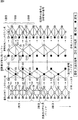
図7は図6の動作を画像全体について、画面上から下方向にウェーブレット変換を行いながら実行する様子を図示したものである。左端の画像入力では、最初のIn-1が7ライン入力で、In-2以降が4ライン入力になっている。中央のウェーブレット変換結果(分析)は、最初のWT-1がレベル1では1ライン、レベル2では3ラインが生成され、WT-2ではレベル1が1ラインでレベル2は2ラインが生成されることを示している。
FIG. 7 illustrates a state in which the operation of FIG. 6 is performed on the entire image while performing wavelet transform from the top to the bottom of the screen. In the leftmost image input, the first In-1 is 7-line input, and In-2 and later are 4-line input. In the center wavelet transform result (analysis), the first WT-1 generates 1 line at
一方、復号側の合成フィルタではWT-1をウェーブレット逆変換することでOut-1の1ラインが得られ、WT-2からは4ラインが生成され、最終ラインは8ラインが生成されることを示している。 On the other hand, the decoding filter on the decoding side obtains one line of Out-1 by inverse wavelet transform of WT-1, 4 lines are generated from WT-2, and 8 lines are generated as the final line. Show.
図8に示されるように、以上のような画像符号化および復号処理の各要素は、並列に実行することができ、より低遅延な処理を実現することができる。 As shown in FIG. 8, each element of the image encoding and decoding processes as described above can be executed in parallel, and a process with lower delay can be realized.
図7を参照して、5×3フィルタを用いて分解レベル=2までウェーブレット変換を行った場合の、画像入力から画像出力までの遅延時間を計算してみる。第1ライン目の画像データが入力されてから、この第1ライン目の画像データが、符号化処理され、伝送され、および復号処理されて出力されるまでの遅延時間は、下記の各要素の総和となる。なお、ここでは、伝送路における遅延や、装置各部の実際の処理タイミングに伴う遅延などの、システムの構成により異なる遅延は、除外している。 Referring to FIG. 7, let us calculate the delay time from image input to image output when wavelet transform is performed up to decomposition level = 2 using a 5 × 3 filter. The delay time from when the image data of the first line is input to when the image data of the first line is encoded, transmitted, decoded and output is as follows. Summed up. Here, delays that differ depending on the system configuration, such as delays in the transmission path and delays associated with actual processing timing of each unit of the apparatus, are excluded.
(1)最初のライン入力から7ライン分のウェーブレット変換WT-1が終了するまでの遅延D_WT
(2)3ライン分の係数並び替えOrd-1に伴う時間D_Ord
(3)3ライン分のエントロピ符号化EC-1に伴う時間D_EC
(4)3ライン分のエントロピ復号iEC-1に伴う時間D_iEC
(5)3ライン分のウェーブレット逆変換iWT-1に伴う時間D_iWT
(1) Delay D_WT from the first line input to the end of wavelet transform WT-1 for 7 lines
(2) Time D_Ord associated with coefficient rearrangement Ord-1 for 3 lines
(3) Time D_EC associated with 3 lines of entropy coding EC-1
(4) Time D_iEC associated with entropy decoding iEC-1 for 3 lines
(5) Time D_iWT associated with wavelet inverse transform iWT-1 for 3 lines
図7を参照して、上述の各要素による遅延の計算を試みる。(1)の遅延D_WTは、10ライン分の時間である。また、並び替えOrd-1が開始されてから1ライン後には、エントロピ符号化EC-1を開始することができる。さらに、エントロピ復号iEC-1が開始されてから2ライン後には、ウェーブレット逆変換iWT-1を開始することができる。また、エントロピ復号iEC-1は、エントロピ符号化EC-1で1ライン分の符号化が終了した時点で処理を開始することができる。 Referring to FIG. 7, an attempt is made to calculate a delay by each of the above-described elements. The delay D_WT in (1) is a time for 10 lines. Further, entropy coding EC-1 can be started one line after the rearrangement Ord-1 is started. Furthermore, wavelet inverse transform iWT-1 can be started two lines after entropy decoding iEC-1 is started. In addition, the entropy decoding iEC-1 can start processing when encoding for one line is completed in the entropy encoding EC-1.
したがって、この図7の例では、第1ライン目の画像データが入力されてから、符号化、伝送、および復号等の各処理が行われ、当該第1ライン目の画像データが出力されるまでの遅延時間は、10+1+1+2+3=17ライン分となる。 Therefore, in the example of FIG. 7, each process such as encoding, transmission, and decoding is performed after the image data of the first line is input until the image data of the first line is output. The delay time is 10 + 1 + 1 + 2 + 3 = 17 lines.
遅延時間について、より具体的な例を挙げて考察する。入力される画像データがHDTV(High Definition Television)のインタレースビデオ信号の場合、例えば1920画素×1080ラインの解像度で1フレームが構成され、1フィールドは、1920画素×540ラインとなる。したがって、フレーム周波数を30Hzとした場合、1フィールドの540ラインが16.67msec(=1sec/60フィールド)の時間に入力されることになる。 Consider the delay time with a more specific example. When the input image data is an HDTV (High Definition Television) interlaced video signal, for example, one frame is formed with a resolution of 1920 pixels × 1080 lines, and one field is 1920 pixels × 540 lines. Therefore, if the frame frequency is 30 Hz, 540 lines in one field are input at a time of 16.67 msec (= 1 sec / 60 fields).
したがって、7ライン分の画像データの入力に伴う遅延時間は、0.216msec(=16.67msec×7/540ライン)であり、例えば1フィールドの更新時間に対して非常に短い時間となる。また、上述した(1)乃至(5)の遅延時間の総和についても、処理対象のライン数が少ないため、遅延時間が非常に短縮される。各処理を行う要素をハードウェア化すれば、処理時間をさらに短縮することも可能である。 Therefore, the delay time associated with the input of the image data for 7 lines is 0.216 msec (= 16.77 msec × 7/540 lines), which is a very short time with respect to the update time of one field, for example. Also, with respect to the sum of the delay times (1) to (5) described above, the delay time is greatly reduced because the number of lines to be processed is small. If the elements for performing each process are implemented as hardware, the processing time can be further shortened.
以上が、図1の構成の前段部のラインブロック符号化部101の説明である。ラインブロック符号化部101のエントロピ符号化部127から出力されたコードストリームは、既に上記で述べた通り、ラインブロック単位でMXFファイル生成部102に送出される。
The above is the description of the line block encoding unit 101 at the front stage of the configuration of FIG. The code stream output from the
[MXFファイル生成部]
MXFファイル生成部102は、ラインブロック符号化部101から供給される符号化データ(コードストリーム)を、ラインブロック毎にMXFファイル化する。このように、符号化データ(コードストリーム)を、従来のようにピクチャ単位やシーケンス単位といった大きな単位でMXFファイル化せずに、そのラインブロック毎にMXFファイル化することにより、MXFファイル生成部102は、より低遅延にMXFファイル化することができる。また、このようにすることにより、MXFファイル生成部102は、供給された符号化データ(コードストリーム)を蓄積するためのメモリ量を低減させることができ、コストの増大を抑制することができる。
[MXF file generator]
The MXF
図1に示されるように、MXFファイル生成部102は、ヘッダパーティション(Header Partition)生成部131、ボディパーティション(Body Partition)生成部132、フッタパーティション(Footer Partition)生成部133、およびパーティション(Partition)統合部134を有する。
As shown in FIG. 1, the MXF
ヘッダパーティション生成部131は、MXFファイルのヘッダパーティションの生成を行う。ヘッダパーティション生成部131は、生成したヘッダパーティションをパーティション統合部134に供給する。
The header
ボディパーティション生成部132は、MXFファイルのボディパーティションの生成を行う。ボディパーティション生成部132は、生成したボディパーティションをパーティション統合部134に供給する。
The body
フッタパーティション生成部133は、MXFファイルのフッタパーティションの生成を行う。フッタパーティション生成部133は、生成したフッタパーティションをパーティション統合部134に供給する。
The footer
パーティション統合部134は、ヘッダパーティション生成部131から供給されるヘッダパーティション、ボディパーティション生成部132から供給されるボディパーティション、および、フッタパーティション生成部133から供給されるフッタパーティションを統合し、MXFファイルを生成する。パーティション統合部134は、生成したMXFファイルを画像符号化装置100の外部に出力し、伝送先に伝送させる。
The
[MXF]
ここで、MXFについて説明する。図9は、非特許文献1に示されているMXFフォーマットの論理的な基本構造図である。MXFファイルは、先頭部にファイルヘッダ(File Header)、中央にファイルボディ(File Body)、後尾にファイルフッタ(File Footer)という論理的な構造を有する。ファイルヘッダには、MXFの特徴であるメタデータを格納することができる。ファイルボディには、映像や音声等のコンテンツを格納することができる。
[MXF]
Here, MXF will be described. FIG. 9 is a logical basic structure diagram of the MXF format shown in
MXFファイルは、上述したような論理的な構造を有するとともに、図10に示されるようなパーティション(Partition)という物理的な構成により区切られる。パーティションで区切られたものをパーティションパック(Partition Pack)と称する。 The MXF file has a logical structure as described above and is divided by a physical configuration called a partition as shown in FIG. What is divided by partitions is called a partition pack.
図10のAに示されるヘッダパーティション(Header Partition)は、ファイルヘッダ等が格納されるパーティションである。より具体的には、ヘッダパーティションは、ヘッダパーティションパック(Header Partition Pack)とヘッダメタデータ(Header Metadata)を有する。また、ヘッダパーティションパックは、オプションとして、インデックステーブルセグメント(Index Table)とエッセンスコンテナデータ(Essence Container)を含むことができる。 A header partition shown in A of FIG. 10 is a partition in which a file header or the like is stored. More specifically, the header partition has a header partition pack and header metadata. The header partition pack may optionally include an index table segment (Index Table) and essence container data (Essence Container).
図10のBに示されるボディパーティション(Body Partition)は、ファイルボディ等が格納されるパーティションである。より具体的には、ボディパーティションは、ボディパーティションパック(Body Partition Pack)を有する。また、ボディパーティションは、オプションとして、ヘッダメタデータ(Header Metadata)、インデックステーブルセグメント(Index Table)、およびエッセンスコンテナデータ(Essence Container)を含むことができる。 A body partition (Body Partition) shown in FIG. 10B is a partition in which a file body or the like is stored. More specifically, the body partition has a body partition pack. The body partition may optionally include header metadata, index table segment (Index Table), and essence container data (Essence Container).
図10のCに示されるフッタパーティション(Footer Partition)は、ファイルフッタ等が格納されるパーティションである。より具体的には、フッタパーティションは、フッタパーティションパック(Footer Partition Pack)を有する。また、フッタパーティションは、オプションとして、ヘッダメタデータ(Header Metadata)およびインデックステーブルセグメント(Index Table)を含むことができる。 A footer partition (Footer Partition) shown in FIG. 10C is a partition in which file footers and the like are stored. More specifically, the footer partition has a footer partition pack. Also, the footer partition can optionally include header metadata and an index table segment.
上述したエッセンスコンテナデータ(Essence Container)については、非特許文献3に定義されている。図11の上段にその基本構造を示す。図11に示されるように、エッセンスコンテナデータは、複数個のCP(Content Packages)を有することができる。ただし、MXFファイル生成部102は、符号化データをラインブロック毎にMXFファイル化し、ラインブロック1個に対してピクチャアイテム(Picture Item)1つを割り当てるため、CP0のみが存在する。
The above-described essence container data (Essence Container) is defined in
図11の中断には、このCPの構成要素が示されている。このCPに含まれるピクチャアイテム(Picture Item)は、図11の下段に示されるように、KLV構造を有する。V(Value)の領域に実際の画像データが記録される。なお、L(Length)には、Vのデータ長が記録される。K(Key)は、このデータを識別するための識別情報(タグ)である。 The interruption of FIG. 11 shows the components of this CP. A picture item included in this CP has a KLV structure as shown in the lower part of FIG. Actual image data is recorded in the area of V (Value). Note that the data length of V is recorded in L (Length). K (Key) is identification information (tag) for identifying this data.
図1のヘッダパーティション生成部131は、図10のAに示されるようなヘッダパーティションを生成する。ボディパーティション生成部132は、図10のBに示されるようなボディパーティションを生成する。フッタパーティション生成部133は、図10のCに示されるようなフッタパーティションを生成する。
The header
[ボディパーティション生成部]
図1に示されるように、ボディパーティション生成部132は、コードストリームデータ長検出部141、エッセンスコンテナデータ(Essence Container Data)生成部142、インデックステーブルセグメント(Index Table Segment)生成部143、およびヘッダメタデータ(Header Metadeta)生成部144を有する。
[Body partition generator]
As shown in FIG. 1, the body
コードストリームデータ長検出部141は、ラインブロック単位のコードストリームのデータ長(例えば100バイトまたは800ビットといったような、実際のデータの長さ)を測定し、そのラインブロック単位のコードストリームとそのデータ長を合わせてエッセンスコンテナデータ生成部142に供給する。
The code stream data
エッセンスコンテナデータ生成部142は、供給されたラインブロック単位のコードストリームとデータ長とを用いて、エッセンスコンテナデータを生成する。より具体的には、エッセンスコンテナデータ生成部142は、供給されたラインブロック単位のコードストリームを、ピクチャアイテム(Picture Item)のVの領域に記録し、そのコードストリームのデータ長をLに記録する。また、エッセンスコンテナデータ生成部142は、Kに、SMPTE(Society of Motion Picture and Television Engineers)規格で定義された情報を記録する。エッセンスコンテナデータ生成部142は、生成したエッセンスコンテナデータをインデックステーブルセグメント生成部143に供給する。
The essence container
インデックステーブルセグメント生成部143は、エッセンスコンテナデータ生成部142から供給されるエッセンスコンテナデータの情報を用いて、インデックステーブルセグメント(Index Table Segment)を生成する。インデックステーブルセグメントは、MXFファイル中にエッセンスコンテナデータが複数存在する場合に、それぞれの位置情報(Indexing)を記述するのに必要なデータ群である。インデックステーブルセグメント生成部143は、生成したインデックステーブルセグメントを、エッセンスコンテナデータとともに、ヘッダメタデータ生成部144に供給する。
The index table
ヘッダメタデータ生成部144は、エッセンスコンテナデータの情報を用いてヘッダメタデータを生成する。図12にヘッダメタデータとエッセンスコンテナデータとの関係の例を示す。この関係は、非特許文献1において定義されている。図12に示されるように、ヘッダメタデータにおいては、画像の連続シーケンスであるエッセンスコンテナデータが、MXFファイル中のピクチャトラック(Picture Track)のどの時刻(Timecode)に存在しているかの関連付けがなされている。この様な画像や音声のメタデータの時系列での関連付けに関する情報等がヘッダメタデータに記述される。
The header
ヘッダメタデータ生成部144は、生成したヘッダメタデータを、インデックステーブルセグメントやエッセンスコンテナデータとともに、パーティション統合部134に供給する。
The header
なお、ヘッダメタデータおよびインデックステーブルセグメントは、オプションであるので、その生成を省略することも出来る。また、インデックステーブルセグメント生成部143が出力するインデックステーブルセグメントおよびエッセンスコンテナデータは、フッタパーティション生成部133に供給され、フッタパーティションの生成に利用されるようにしてもよい。
Note that the header metadata and the index table segment are optional and can be omitted. Further, the index table segment and the essence container data output from the index table
[パーティションの低遅延用データ構造]
以上のようなMXFファイル化の際に、ヘッダパーティション生成部131乃至フッタパーティション生成部133は、より低遅延にMXFファイルを伝送することができるように、それぞれのパーティションのデータ構造を、低遅延用のデータ構造にする。
[Data structure for partition low latency]
When the MXF file is created as described above, the header
図13は、各パーティションの低遅延用データ構造の例を示す図である。ヘッダパーティション生成部131は、図13Aに示されるようなデータ構造のヘッダパーティションを生成する。つまり、ヘッダパーティション生成部131は、必須以外のものは不要であるので、ヘッダパーティションパックとヘッダメタデータを構成要素とするヘッダパーティションを生成する(オプションは含めない)。
FIG. 13 is a diagram illustrating an example of a low-latency data structure of each partition. The header
ボディパーティション生成部132は、図13Bに示されるようなデータ構造のボディパーティションを生成する。つまり、ボディパーティション生成部132は、ボディパーティションの先頭に位置するフラグ情報であるボディパーティションパックとヘッダメタデータとを構成要素とするボディパーティション、ボディパーティションパックとインデックステーブルセグメントとを構成要素とするボディパーティション、並びに、ボディパーティションパックとエッセンスコンテナデータとを構成要素とするボディパーティションを生成する。
The body
なお、上述したように、ラインブロックのコードストリームはエッセンスコンテナデータに書き込まれた後、その情報を元にしてインデックステーブルセグメントが生成され、ヘッダメタデータが生成される。したがって、ボディパーティション生成部132は、これらのボディパーティションの生成による遅延時間の増大を抑制するために、この順序にしたがって各ボディパーティションを生成する。
As described above, after the code stream of the line block is written in the essence container data, an index table segment is generated based on the information, and header metadata is generated. Therefore, the body
つまり、ボディパーティション生成部132は、最初に、ボディパーティションパックとエッセンスコンテナデータとを構成要素とする先頭のボディパーティションを生成し、次に、ボディパーティションパックとインデックステーブルセグメントとを構成要素とする2番目のボディパーティションを生成し、その次に、ボディパーティションパックとヘッダメタデータとを構成要素とする3番目のボディパーティションを生成する。つまり、この順に並ぶボディパーティション群が生成される。
In other words, the body
フッタパーティション生成部133は、図13Cに示されるようなデータ構造のフッタパーティションを生成する。つまり、フッタパーティション生成部133は、フッタパーティションパック、ヘッダメタデータ、および、1個若しくは複数個のインデックステーブルセグメントを構成要素とするフッタパーティションを生成する。
The footer
このように、各パーティションに不要な構成が含まれないようにし、各パーティションの構成をできるだけ少なくするようにMXFファイルを生成する(低遅延用のデータ構造のMXFファイルを生成する)ことにより、MXFファイル生成部102は、MXFファイルの授受をより容易にし、より低遅延にMXFファイルのデータ伝送を行うことができるようにすることができる。
In this way, MXF files are generated so that each partition does not contain unnecessary configurations and the configuration of each partition is reduced as much as possible (generates an MXF file with a data structure for low latency). The
以上のように、MXFファイル生成部102は、低遅延に生成された符号化データに対応した方法でMXFファイルを生成することができる。これにより、画像符号化装置100は、画像や音声等のデータ伝送の、高自由度化および低遅延化を実現することができる。
As described above, the MXF
[符号化処理の流れ]
次に、以上のような画像符号化装置100により実行される各処理の流れについて説明する。最初に、図14のフローチャートを参照して、画像符号化装置100により実行される符号化処理の流れの例を説明する。
[Flow of encoding process]
Next, the flow of each process executed by the image encoding device 100 as described above will be described. Initially, with reference to the flowchart of FIG. 14, the example of the flow of the encoding process performed by the image coding apparatus 100 is demonstrated.
画像符号化装置100は、図14に示される符号化処理を、入力される画像データのピクチャ毎に実行する。 The image encoding device 100 executes the encoding process shown in FIG. 14 for each picture of input image data.
符号化処理が開始されると、ラインブロック符号化部101は、ステップS101において、1ラインブロック分の入力画像データの符号化を行う。 When the encoding process is started, the line block encoding unit 101 encodes input image data for one line block in step S101.
ステップS102において、コードストリームデータ長検出部141は、ステップS101の処理により生成された1ラインブロック分のコードストリーム(V)のデータ長(L)を検出する。
In step S102, the code stream data
ステップS103において、ボディパーティション生成部132は、例えば図13のBに示されるような低遅延用データ構造のボディパーティションを生成する。
In step S103, the body
ステップS104において、ヘッダパーティション生成部131は、例えば図13のAに示されるような、低遅延用データ構造のヘッダパーティションを生成する。
In step S104, the header
ステップS105において、フッタパーティション生成部133は、例えば図13のCに示されるような、低遅延用データ構造のフッタパーティションを生成する。
In step S105, the footer
ステップS106において、パーティション統合部134は、ステップS104の処理により生成されたヘッダパーティション、ステップS103の処理により生成されたボディパーティション、並びに、ステップS105の処理により生成されたフッタパーティションを、この順に統合して1ラインブロック分のコードストリームを格納するMXFファイルを生成する。パーティション統合部134は、生成したMXFファイルを画像符号化装置100の外部に出力する。
In step S106, the
このMXFファイルは、例えば有線や無線のネットワーク等の任意の伝送媒体や、ハードディスク等任意の記録媒体を介して他の装置(例えば画像符号化装置100に対応する画像復号装置)に伝送される。 The MXF file is transmitted to another device (for example, an image decoding device corresponding to the image encoding device 100) via an arbitrary transmission medium such as a wired or wireless network or an arbitrary recording medium such as a hard disk.
ステップS107において、パーティション統合部134は、処理対象のピクチャ(注目ピクチャ)について、全てのラインブロックを処理したか否かを判定し、未処理のラインブロックが存在すると判定した場合、処理をステップS101に戻し、それ以降の処理を繰り返す。
In step S107, the
ステップS101乃至ステップS107の各処理が各ラインブロックに対して実行され、ステップS107において、注目ピクチャの全てのラインブロックが処理されたと判定した場合、パーティション統合部134は、符号化処理を終了する。
If each process of step S101 to step S107 is executed for each line block and it is determined in step S107 that all the line blocks of the target picture have been processed, the
[ラインブロック符号化処理の流れ]
次に、図15のフローチャートを参照して、図14のステップS101において実行されるラインブロック符号化処理の流れの例を説明する。
[Flow of line block encoding process]
Next, an example of the flow of the line block encoding process executed in step S101 of FIG. 14 will be described with reference to the flowchart of FIG.
ラインブロック符号化処理が開始されると、画像ライン入力部121は、ステップS121において、1ラインブロック分の画像データを取得し、途中計算用バッファ122に蓄積する。
When the line block encoding process is started, the image
1ラインブロック分の画像データが蓄積されると、ステップS122において、ラインベースウェーブレット変換部123は、その1ラインブロック分の画像データに対して、垂直方向の分析フィルタ処理である垂直分析フィルタリングを行う。なお、上述したように、この垂直分析フィルタリングをリフティング演算によって行う場合、ラインベースウェーブレット変換部123は、3ライン分の画像データが蓄積された時点で、この垂直分析フィルタリングを開始することができる。つまり、ラインベースウェーブレット変換部123は、1ラインブロック分の画像データが途中計算用バッファ122に蓄積される前に、垂直分析フィルタリングを開始することができる。
When image data for one line block is accumulated, in step S122, the line-based
垂直分析フィルタリングが終了すると、ラインベースウェーブレット変換部123は、次に、ステップS123において、その垂直分析フィルタリング結果に対して、水平方向の分析フィルタ処理である水平分析フィルタリングを行う。垂直分析フィルタリングにより画像データは、垂直方向に低域な成分と高域な成分とに分離される。水平分析フィルタリングは、これらの各成分に対して行われ、それぞれが水平方向に低域な成分と高域な成分とに分離される。したがって、ステップS122およびステップS123の処理により、画像データから4つのサブバンドが生成される。
When the vertical analysis filtering ends, the line-based
ステップS124において、ラインベースウェーブレット変換部123は、予め定められた最終分割レベルまで分析フィルタリングを行ったか否かを判定し、最終分割レベルまで行われていないと判定した場合、処理をステップS122に戻し、それ以降の処理を繰り返す。
In step S124, the line-based
処理をステップS122に戻すと、ラインベースウェーブレット変換部123は、分割レベルを1つ進め、前回の分析フィルタリングにより生成された4つのサブバンドの内、垂直方向および水平方向の両方に低域な成分のサブバンドの係数データに対して、ステップS122およびステップS123の処理(垂直分析フィルタリングおよび水平分析フィルタリング)を実行する。これにより、垂直方向および水平方向の両方に低域な成分のサブバンドが、さらに4つのサブバンドに分割される。
When the process returns to step S122, the line-based
以上のように、ラインベースウェーブレット変換部123は、分析フィルタリングにより得られた垂直方向および水平方向の両方に低域な成分のサブバンドに対して、ステップS122およびステップS123の処理を最終分割レベルまで再帰的に繰り返す。
As described above, the line-based
ステップS124において、以上のような分析フィルタリングが最終分割レベルに達したと判定した場合、ラインベースウェーブレット変換部123は、処理をステップS125に進める。
If it is determined in step S124 that the above analysis filtering has reached the final division level, the line-based
ラインベースウェーブレット変換部123は、ステップS122およびステップS123の各処理の処理結果として出力される各サブバンドの係数データを係数並び替え用バッファ124に記憶させる。つまり、ラインベースウェーブレット変換部123は、高域成分から低域成分に向かう順に係数データを係数並び替え用バッファ124に記憶させる。
The line-based
ステップS125において、係数並び替え部125は、係数並び替え用バッファ124に記憶されている各サブバンドの係数データを、合成フィルタリングに使用される順、すなわち、低域成分から高域成分に向かう順に読み出すことにより、係数データを並べ替える。
In step S125, the
ステップS126において、量子化部126は、ステップS125において並び替えられた順に各係数データを量子化する。
In step S126, the
ステップS127において、エントロピ符号化部127は、ステップS126において量子化された係数データをエントロピ符号化し、生成された符号化データ(コードストリーム)を出力する。
In step S127, the
ステップS127の処理が終了すると、エントロピ符号化部127は、ラインブロック符号化処理を終了し、処理を図14に戻す。
When the process of step S127 ends, the
[ボディパーティション生成処理の流れ]
次に、図16のフローチャートを参照して、図14のステップS103において実行されるボディパーティション生成処理の流れの例を説明する。
[Flow of body partition generation processing]
Next, an example of the flow of the body partition generation process executed in step S103 in FIG. 14 will be described with reference to the flowchart in FIG.
ボディパーティション生成処理が開始されると、エッセンスコンテナデータ生成部142は、ステップS141において、図14のステップS101の処理により生成された符号化データ(コードストリーム)を用いて、エッセンスコンテナデータのKLVを生成し、図13のBに示されるような、そのエッセンスコンテナデータを含む低遅延用データ構造のボディパーティションを、先頭のボディパーティション(1st Body Partition)として生成する。
When the body partition generation process is started, the essence container
ステップS142において、インデックステーブルセグメント生成部143は、ステップS141において生成されたエッセンスコンテナデータの情報を用いて、インデックステーブルセグメントを生成する。インデックステーブルセグメント生成部143は、図13のBに示されるような、そのインデックステーブルセグメントを含む低遅延用データ構造のボディパーティションを生成する。インデックステーブルセグメント生成部143は、そのインデックステーブルセグメントを含むボディパーティションを、ステップS141において生成された先頭のボディパーティションに続く2番目のボディパーティション(2nd Body Partition)として生成する。つまり、インデックステーブルセグメント生成部143は、インデックステーブルセグメントを含むボディパーティションを、エッセンスコンテナデータを含むボディパーティションの後に付加する。
In step S142, the index table
ステップS143において、ヘッダメタデータ生成部144は、ステップS141において生成されたエッセンスコンテナデータの情報や、ステップS142において生成されたインデックステーブルセグメントの情報を用いてヘッダメタデータを生成する。ヘッダメタデータ生成部144は、図13のBに示されるような、そのヘッダメタデータを含む低遅延用データ構造のボディパーティションを生成する。ヘッダメタデータ生成部144は、そのヘッダメタデータを含むボディパーティションを、ステップS142において生成された2番目のボディパーティションに続く3番目のボディパーティション(3rd Body Partition)として生成する。つまり、ヘッダメタデータ生成部144は、ヘッダメタデータを含むボディパーティションを、インデックステーブルセグメントを含むボディパーティションの後に付加する。
In step S143, the header
以上のように3種類のボディパーティションを生成すると、ヘッダメタデータ生成部144は、ボディパーティション生成処理を終了し、処理を図14に戻す。
When the three types of body partitions are generated as described above, the header
[フッタパーティション生成処理の流れ]
次に、図17のフローチャートを参照して、図14のステップS105において実行されるフッタパーティション生成処理の流れの例を説明する。
[Footer partition generation process flow]
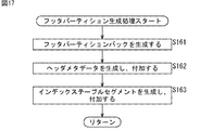
Next, an example of the flow of the footer partition generation process executed in step S105 of FIG. 14 will be described with reference to the flowchart of FIG.
フッタパーティション生成処理が開始されると、フッタパーティション生成部133は、ステップS161において、フッタパーティションパックを生成する。
When the footer partition generation process is started, the footer
ステップS162において、フッタパーティション生成部133は、ヘッタメタデータを生成し、図13のCに示されるように、ステップS161において生成されたフッタパーティションパックの後に付加する。
In step S162, the footer
ステップS163において、フッタパーティション生成部133は、インデックステーブルセグメントを生成し、図13のCに示されるように、ステップS162においてフッタパーティションパックに付加されたヘッダメタデータの後に付加する。
In step S163, the footer
以上のように、低遅延データ構造のフッタパーティションを生成すると、フッタパーティション生成部133は、フッタパーティション生成処理を終了し、処理を図14に戻す。
As described above, when the footer partition having the low-latency data structure is generated, the footer
以上のように各処理を行うことにより、ラインブロック符号化部101は、画像データを低遅延に符号化して符号化データ(コードストリーム)を生成することができる。また、MXFファイル生成部102は、遅延時間を不要に増大させずに、その符号化データ(コードストリーム)をMXFファイル化することができる。
By performing each process as described above, the line block encoding unit 101 can generate encoded data (code stream) by encoding image data with low delay. Further, the MXF
したがって、画像符号化装置100は、画像や音声等のデータ伝送の、高自由度化および低遅延化を実現することができる。 Therefore, the image coding apparatus 100 can realize a high degree of freedom and a low delay in data transmission of images and sounds.
[ボディパーティションの省略]
図18のAは、エッセンスコンテナデータ内に1個のラインブロックのコードストリームだけが存在するMXFファイルの構造例を示す図である。この例に示されるように、3番目のボディパーティションのヘッダメタデータと、後続のフッタパーティションの先頭のヘッダメタデータとが重複する。
[Omit body partition]
FIG. 18A is a diagram showing an example of the structure of an MXF file in which only one line block code stream exists in the essence container data. As shown in this example, the header metadata of the third body partition overlaps with the header metadata of the head of the subsequent footer partition.
従って図18のBに示されるように、3番目のボディパーティション(ヘッダメタデータを含むボディパーティション)を省略し(付加しないようにし)てもよい。つまり、最後尾のボディパーティションは、2番目のボディパーティション(インデックステーブルセグメントを含むボディパーティション)としてもよい。その代わり、省略した(付加しなかった)ヘッダメタデータの情報は、フッタパーティションに含まれるヘッダメタデータに含めるようにする。 Therefore, as shown in FIG. 18B, the third body partition (body partition including header metadata) may be omitted (not added). That is, the last body partition may be a second body partition (a body partition including an index table segment). Instead, the omitted (not added) header metadata information is included in the header metadata included in the footer partition.
このようにボディパーティションおよびフッタパーティションを生成することにより、MXFファイル生成部102は、MXFファイルの情報量を低減させることができる。
By generating the body partition and the footer partition in this way, the MXF
この場合、画像符号化装置100により実行される符号化処理は、図14のフローチャートを参照して説明した場合と同様に実行される。また、ラインブロック符号化部101により実行されるラインブロック符号化処理は、図15のフローチャートを参照して説明した場合と同様に実行される。ただし、ボディパーティション生成処理およびフッタパーティション生成処理は、以下のように実行される。 In this case, the encoding process executed by the image encoding device 100 is executed similarly to the case described with reference to the flowchart of FIG. Further, the line block encoding process executed by the line block encoding unit 101 is executed similarly to the case described with reference to the flowchart of FIG. However, the body partition generation process and the footer partition generation process are executed as follows.
[ボディパーティション生成処理の流れ]
図19のフローチャートを参照して、この場合のボディパーティション生成処理の流れの例を説明する。この処理は、図16のフローチャートを参照して説明したボディパーティション生成処理に対応する、図14のステップS103において実行される処理である。
[Flow of body partition generation processing]
An example of the flow of body partition generation processing in this case will be described with reference to the flowchart of FIG. This process is a process executed in step S103 of FIG. 14 corresponding to the body partition generation process described with reference to the flowchart of FIG.
ボディパーティション生成処理が開始されると、ステップS181およびステップS182の各処理が、図16のステップS141およびステップS142の各処理と同様に実行される。 When the body partition generation process is started, the processes in steps S181 and S182 are executed in the same manner as the processes in steps S141 and S142 in FIG.
すなわち、エッセンスコンテナデータを含む低遅延用データ構造のボディパーティション(先頭のボディパーティション)と、インデックステーブルセグメントを含む低遅延用データ構造のボディパーティション(2番目のボディパーティション)とが、図16の場合と同様に生成される。 That is, the body partition (first body partition) of the low-delay data structure including the essence container data and the body partition (second body partition) of the low-delay data structure including the index table segment are shown in FIG. Is generated in the same way.
ステップS183において、ヘッダメタデータ生成部144は、ステップS181において生成されたエッセンスコンテナデータの情報や、ステップS182において生成されたインデックステーブルセグメントの情報を用いてヘッダメタデータを生成する。ここで、ヘッダメタデータ生成部144は、ヘッダメタデータを含むボディパーティションを生成せずに、ボディパーティション生成処理を終了し、処理を図14に戻す。
In step S183, the header
つまり、この場合、図18のBに示される例のように、先頭のボディパーティション(1st Body Partition)と2番目のボディパーティション(2nd Body Partition)の2種類のボディパーティションが生成される。 That is, in this case, as in the example shown in FIG. 18B, two types of body partitions are generated: a first body partition (1st Body Partition) and a second body partition (2nd Body Partition).
[フッタパーティション生成処理の流れ]
次に、図20のフローチャートを参照して、この場合のフッタパーティション生成処理の流れの例を説明する。この処理は、図17のフローチャートを参照して説明したフッタパーティション生成処理に対応する、図14のステップS105において実行される処理である。
[Footer partition generation process flow]
Next, an example of the flow of the footer partition generation process in this case will be described with reference to the flowchart of FIG. This process is a process executed in step S105 of FIG. 14 corresponding to the footer partition generation process described with reference to the flowchart of FIG.
フッタパーティション生成処理が開始されると、ステップS201において、フッタパーティション生成部133は、ステップS161の場合と同様に、フッタパーティションパックを生成する。
When the footer partition generation process is started, in step S201, the footer
ステップS202において、フッタパーティション生成部133は、図19のステップS183において生成されたボディパーティションのヘッタメタデータを、ステップS201において生成されたフッタパーティションパックの後に付加する。
In step S202, the footer
ステップS203において、フッタパーティション生成部133は、インデックステーブルセグメントを生成し、ステップS202においてフッタパーティションパックに付加されたヘッダメタデータの後に付加する。
In step S203, the footer
つまり、この場合、フッタパーティション生成部133は、図18のBに示される例のように、図13のCの場合と同様の構成の(ヘッダメタデータとインデックステーブルセグメントを含む)フッタパーティションを生成する。ただし、このヘッダメタデータには、ボディパーティションのヘッダメタデータの内容が含まれる。
That is, in this case, the footer
以上のように、低遅延データ構造のフッタパーティションを生成すると、フッタパーティション生成部133は、フッタパーティション生成処理を終了し、処理を図14に戻す。
As described above, when the footer partition having the low-latency data structure is generated, the footer
以上のように各処理を行うことにより、MXFファイル生成部102は、図14乃至図17を参照して説明した場合よりもMXFファイルの情報量を低減させることができる。
By performing each processing as described above, the MXF
[ボディパーティションの省略2]
図21のAは、エッセンスコンテナデータ内に1個のラインブロックのコードストリームだけが存在するMXFファイルの構造例を示す図である。この例に示されるように、フッタパーティションには、ヘッダメタデータだけでなく、インデックステーブルセグメントも含まれる。
[Body partition abbreviation 2]
FIG. 21A shows an example of the structure of an MXF file in which only one line block code stream exists in the essence container data. As shown in this example, the footer partition includes not only header metadata but also an index table segment.
従って図21のBに示されるように、3番目のボディパーティション(ヘッダメタデータを含むボディパーティション)だけでなく、2番目のボディパーティション(インデックステーブルセグメントを含むボディパーティション)も省略し(付加しないようにし)てもよい。つまり、ボディパーティションは、先頭のボディパーティション(エッセンスコンテナデータを含むボディパーティション)のみとしてもよい。その代わり、省略した(付加しなかった)ヘッダメタデータとインデックステーブルセグメントの情報は、それぞれ、フッタパーティションに含まれるヘッダメタデータとインデックステーブルセグメントに含めるようにする。 Therefore, as shown in FIG. 21B, not only the third body partition (body partition including header metadata) but also the second body partition (body partition including index table segment) is omitted (not added). You may) That is, the body partition may be only the first body partition (body partition including essence container data). Instead, the omitted header metadata and index table segment information are included in the header metadata and index table segment included in the footer partition, respectively.
このようにボディパーティションおよびフッタパーティションを生成することにより、MXFファイル生成部102は、MXFファイルの情報量をさらに低減させることができる。
By generating the body partition and the footer partition in this way, the MXF
この場合、画像符号化装置100により実行される符号化処理は、図14のフローチャートを参照して説明した場合と同様に実行される。また、ラインブロック符号化部101により実行されるラインブロック符号化処理は、図15のフローチャートを参照して説明した場合と同様に実行される。ただし、ボディパーティション生成処理およびフッタパーティション生成処理は、以下のように実行される。 In this case, the encoding process executed by the image encoding device 100 is executed similarly to the case described with reference to the flowchart of FIG. Further, the line block encoding process executed by the line block encoding unit 101 is executed similarly to the case described with reference to the flowchart of FIG. However, the body partition generation process and the footer partition generation process are executed as follows.
[ボディパーティション生成処理の流れ]
図22のフローチャートを参照して、この場合のボディパーティション生成処理の流れの例を説明する。この処理は、図16や図19のフローチャートを参照して説明したボディパーティション生成処理に対応する、図14のステップS103において実行される処理である。
[Flow of body partition generation processing]
An example of the flow of body partition generation processing in this case will be described with reference to the flowchart of FIG. This process is a process executed in step S103 of FIG. 14 corresponding to the body partition generation process described with reference to the flowcharts of FIGS.
ボディパーティション生成処理が開始されると、ステップS221の処理が、図16のステップS141の処理と同様に実行される。 When the body partition generation process is started, the process of step S221 is executed in the same manner as the process of step S141 of FIG.
すなわち、エッセンスコンテナデータを含む低遅延用データ構造のボディパーティション(先頭のボディパーティション)が、図16の場合と同様に生成される。 That is, a body partition (first body partition) having a low-latency data structure including essence container data is generated in the same manner as in FIG.
ステップS222において、インデックステーブルセグメント生成部143は、ステップS221において生成されたエッセンスコンテナデータの情報を用いて、インデックステーブルセグメントを生成する。ここで、インデックステーブルセグメント生成部143は、インデックステーブルセグメントを含むボディパーティションを生成せずに、処理をステップS223に進める。
In step S222, the index table
ステップS223において、ヘッダメタデータ生成部144は、ステップS221において生成されたエッセンスコンテナデータの情報や、ステップS222において生成されたインデックステーブルセグメントの情報を用いてヘッダメタデータを生成する。ここで、ヘッダメタデータ生成部144は、ステップS183の場合と同様に、ヘッダメタデータを含むボディパーティションを生成せずに、ボディパーティション生成処理を終了し、処理を図14に戻す。
In step S223, the header
つまり、この場合、図21のBに示される例のように、ボディパーティションとしては先頭のボディパーティション(1st Body Partition)のみが生成される。 That is, in this case, only the first body partition (1st Body Partition) is generated as the body partition, as in the example shown in B of FIG.
[フッタパーティション生成処理の流れ]
次に、図23のフローチャートを参照して、この場合のフッタパーティション生成処理の流れの例を説明する。この処理は、図17や図20のフローチャートを参照して説明したフッタパーティション生成処理に対応する、図14のステップS105において実行される処理である。
[Footer partition generation process flow]
Next, an example of the flow of the footer partition generation process in this case will be described with reference to the flowchart of FIG. This process is a process executed in step S105 of FIG. 14 corresponding to the footer partition generation process described with reference to the flowcharts of FIGS.
フッタパーティション生成処理が開始されると、ステップS241において、フッタパーティション生成部133は、ステップS161の場合と同様に、フッタパーティションパックを生成する。
When the footer partition generation process is started, in step S241, the footer
ステップS242において、フッタパーティション生成部133は、図22のステップS223において生成されたボディパーティションのヘッタメタデータを、ステップS241において生成されたフッタパーティションパックの後に付加する。
In step S242, the footer
ステップS243において、フッタパーティション生成部133は、図22のステップS222において生成されたボディパーティションのインデックステーブルセグメントを、ステップS242においてフッタパーティションパックに付加されたヘッダメタデータの後に付加する。
In step S243, the footer
つまり、この場合、フッタパーティション生成部133は、図21のBに示される例のように、図13のCの場合と同様の構成の(ヘッダメタデータとインデックステーブルセグメントを含む)フッタパーティションを生成する。ただし、このヘッダメタデータには、ボディパーティションのヘッダメタデータの内容が含まれ、インデックステーブルセグメントには、ボディパーティションのインデックステーブルセグメントの内容が含まれる。
That is, in this case, the footer
以上のように、低遅延データ構造のフッタパーティションを生成すると、フッタパーティション生成部133は、フッタパーティション生成処理を終了し、処理を図14に戻す。
As described above, when the footer partition having the low-latency data structure is generated, the footer
以上のように各処理を行うことにより、MXFファイル生成部102は、図18乃至図20を参照して説明した場合よりもMXFファイルの情報量をさらに低減させることができる。
By performing each process as described above, the MXF
[複数ラインブロックを含むMXFファイル]
以上においては、符号化データのMXFファイル化を1ラインブロック毎に行うように説明したが、これに限らず、複数ラインブロックの符号化データを1つのMXFファイルに格納するようにしてもよい。
[MXF file containing multiple line blocks]
In the above description, the encoded data is converted into MXF files for each line block. However, the present invention is not limited to this, and encoded data of a plurality of line blocks may be stored in one MXF file.
ただし、遅延時間は、ラインブロックの数に比例する。すなわち、例えばNラインブロックの符号化データを1つのMXFファイルに格納する場合、その遅延時間は、1ラインブロックの符号化データを1つのMXFファイルに格納する場合のN倍となる。 However, the delay time is proportional to the number of line blocks. That is, for example, when storing encoded data of N line blocks in one MXF file, the delay time is N times that when storing encoded data of one line block in one MXF file.
システムに対する遅延時間の要求において許容範囲内であれば、このように遅延時間の増大を前提にして複数ラインブロックの符号化データを1つのMXFファイルに格納するようにしてもよい。例えば、遅延時間に対する要求が低い場合や、MXFファイルを伝送させる伝送路の帯域が広く、1度に多くのデータを伝送可能な場合、遅延時間に対する許容度(マージン)が大きく、複数ラインブロックの符号化データを1つのMXFファイルに格納することができる場合がある。 If the delay time requirement for the system is within an allowable range, encoded data of a plurality of line blocks may be stored in one MXF file on the premise of an increase in the delay time. For example, when the demand for delay time is low, or the bandwidth of the transmission path for transmitting MXF files is wide and a large amount of data can be transmitted at one time, the tolerance (margin) for delay time is large, and multiple line blocks In some cases, encoded data can be stored in one MXF file.
図24は、このように、複数ラインブロックの符号化データを1つのMXFファイルに格納する場合の例を示す図である。図24に示されるように、この場合も、ボディパーティションは、ラインブロック毎に生成される。つまり、ラインブロック毎に、先頭のボディパーティション乃至3番目のボディパーティションが生成され、その直前に生成されたボディパーティションの後に付加される。 FIG. 24 is a diagram illustrating an example of storing encoded data of a plurality of line blocks in one MXF file as described above. As shown in FIG. 24, in this case as well, a body partition is generated for each line block. That is, for each line block, the first body partition to the third body partition are generated and added after the body partition generated immediately before.
ただし、この場合、図24に示されるように、フッタパーティションには、各ラインブロックに対応するインデックステーブルセグメントが格納される。つまり、フッタパーティションのヘッダメタデータの後には、そのMXFファイルに格納された符号化データのラインブロック数分のインデックステーブルセグメントが付加される。 In this case, however, as shown in FIG. 24, an index table segment corresponding to each line block is stored in the footer partition. That is, after the header metadata of the footer partition, as many index table segments as the number of line blocks of encoded data stored in the MXF file are added.
[符号化処理の流れ]
図25のフローチャートを参照して、複数ラインブロック分の符号化データを1つのMXFファイルに格納する場合の符号化処理の流れの例を説明する。この処理は、図14のフローチャートを参照して説明した符号化処理に対応する処理である。したがって、画像符号化装置100は、図25に示される符号化処理を、入力される画像データのピクチャ毎に実行する。
[Flow of encoding process]
With reference to the flowchart of FIG. 25, an example of the flow of an encoding process when encoding data for a plurality of line blocks is stored in one MXF file will be described. This process is a process corresponding to the encoding process described with reference to the flowchart of FIG. Therefore, the image encoding device 100 executes the encoding process shown in FIG. 25 for each picture of input image data.
なお、ここでは、N(Nは2以上の整数)ラインブロック分の符号化データを1つのMXFファイルに格納するものとする。 Here, it is assumed that encoded data for N (N is an integer of 2 or more) line blocks are stored in one MXF file.
符号化処理が開始されると、ラインブロック符号化部101は、ステップS301において、ステップS101の場合と同様にラインブロック符号化処理を行い、1ラインブロック分の入力画像データの符号化を行う。つまり、図15のフローチャートを参照して説明した場合と同様のラインブロック符号化処理が実行される。 When the encoding process is started, the line block encoding unit 101 performs the line block encoding process in step S301 as in step S101, and encodes input image data for one line block. That is, the same line block encoding process as that described with reference to the flowchart of FIG. 15 is executed.
ステップS302において、コードストリームデータ長検出部141は、ステップS102の場合と同様に、ステップS301の処理により生成された1ラインブロック分のコードストリーム(V)のデータ長(L)を検出する。
In step S302, the code stream data
ステップS303において、ボディパーティション生成部132は、ステップS103の場合と同様にボディパーティション生成処理を実行し、例えば図13のBに示されるような低遅延用データ構造のボディパーティションを生成する。つまり、図16のフローチャートを参照して説明した場合と同様のボディパーティション生成処理が実行される。
In step S303, the body
ステップS304において、パーティション統合部134は、(N−1)ラインブロック分の画像データを処理したか否かを判定する。処理した画像データのラインブロック数が(N−2)以下である場合、パーティション統合部134は、処理をステップS301に戻し、それ以降の処理を繰り返す。
In step S304, the
ステップS301乃至ステップS304の各処理がラインブロック毎に繰り返され、ステップS304において、(N−1)ラインブロック分の画像データを処理したと判定された場合、パーティション統合部134は、処理をステップS305に進め、最後の(N番目の)ラインブロックの処理を開始する。
When the processes in steps S301 to S304 are repeated for each line block, and it is determined in step S304 that the image data for (N-1) line blocks has been processed, the
ステップS305において、ラインブロック符号化部101は、N番目のラインブロックを、ステップS301の場合と同様に符号化する。つまり、図15のフローチャートを参照して説明した場合と同様のラインブロック符号化処理が実行される。 In step S305, the line block encoding unit 101 encodes the Nth line block in the same manner as in step S301. That is, the same line block encoding process as that described with reference to the flowchart of FIG. 15 is executed.
ステップS306において、コードストリームデータ長検出部141は、N番目のラインブロックについて、ステップS302の場合と同様に、ステップS305の処理により生成されたN番目のラインブロック分のコードストリーム(V)のデータ長(L)を検出する。
In step S306, for the Nth line block, the code stream data
ステップS307において、ボディパーティション生成部132は、N番目のラインブロックについて、ステップS303の場合と同様にボディパーティション生成処理を実行し、例えば図13のBに示されるような低遅延用データ構造のボディパーティションを生成する。つまり、図16のフローチャートを参照して説明した場合と同様のボディパーティション生成処理が実行される。
In step S307, the body
以上のようにしてNラインブロック分のボディパーティションが生成されると、ステップS308において、ヘッダパーティション生成部131は、ステップS104の場合と同様に、例えば図13のAに示されるような、低遅延用データ構造のヘッダパーティションを生成する。
When the body partition for N line blocks is generated as described above, in step S308, the header
ステップS309において、フッタパーティション生成部133は、フッタパーティション生成処理を実行し、例えば図24に示されるような、低遅延用データ構造のフッタパーティションを生成する。
In step S309, the footer
ステップS310において、パーティション統合部134は、ステップS106の場合と同様に、ステップS308の処理により生成されたヘッダパーティション、ステップS303の処理により生成されたボディパーティション、ステップS307の処理により生成されたボディパーティション、並びに、ステップS309の処理により生成されたフッタパーティションを、この順に統合してNラインブロック分のコードストリームを格納するMXFファイルを生成する。パーティション統合部134は、生成したMXFファイルを画像符号化装置100の外部に出力する。
In step S310, the
このMXFファイルは、例えば有線や無線のネットワーク等の任意の伝送媒体や、ハードディスク等任意の記録媒体を介して他の装置(例えば画像符号化装置100に対応する画像復号装置)に伝送される。 The MXF file is transmitted to another device (for example, an image decoding device corresponding to the image encoding device 100) via an arbitrary transmission medium such as a wired or wireless network or an arbitrary recording medium such as a hard disk.
ステップS311において、パーティション統合部134は、処理対象のピクチャ(注目ピクチャ)について、全てのラインブロックを処理したか否かを判定し、未処理のラインブロックが存在すると判定した場合、処理をステップS301に戻し、それ以降の処理を繰り返す。
In step S311, the
ステップS301乃至ステップS311の各処理が適宜各ラインブロックに対して実行され、ステップS311において、注目ピクチャの全てのラインブロックが処理されたと判定した場合、パーティション統合部134は、符号化処理を終了する。
Each process of step S301 to step S311 is appropriately executed for each line block, and when it is determined in step S311 that all the line blocks of the target picture have been processed, the
[フッタパーティション生成処理の流れ]
次に、図26のフローチャートを参照して、図25のステップS309において実行されるフッタパーティション生成処理の流れの例を説明する。
[Footer partition generation process flow]
Next, an example of the flow of the footer partition generation process executed in step S309 in FIG. 25 will be described with reference to the flowchart in FIG.
フッタパーティション生成処理が開始されると、ステップS331において、フッタパーティション生成部133は、ステップS161の場合と同様に、フッタパーティションパックを生成する。
When the footer partition generation process is started, in step S331, the footer
ステップS332において、フッタパーティション生成部133は、ステップS162の場合と同様に、ヘッタメタデータを生成し、図24に示されるように、ステップS331において生成されたフッタパーティションパックの後に付加する。
In step S332, the footer
ステップS333において、フッタパーティション生成部133は、各ラインブロックについてインデックステーブルセグメントを生成し、そのNラインブロック分のインデックステーブルセグメントを、図24に示されるように、ステップS332においてフッタパーティションパックに付加されたヘッダメタデータの後に付加する。
In step S333, the footer
以上のように、低遅延データ構造のフッタパーティションを生成すると、フッタパーティション生成部133は、フッタパーティション生成処理を終了し、処理を図25に戻す。
As described above, when the footer partition having the low-latency data structure is generated, the footer
以上のように各処理を行うことにより、ラインブロック符号化部101は、画像データを低遅延に符号化して符号化データ(コードストリーム)を生成することができる。また、MXFファイル生成部102は、Nラインブロック分の符号化データ(コードストリーム)を1つのMXFファイルに格納することができる。
By performing each process as described above, the line block encoding unit 101 can generate encoded data (code stream) by encoding image data with low delay. Also, the MXF
したがって、画像符号化装置100は、画像や音声等のデータ伝送の、高自由度化および低遅延化を実現することができる。 Therefore, the image coding apparatus 100 can realize a high degree of freedom and a low delay in data transmission of images and sounds.
[ボディパーティションの省略3]
なお、このように、Nラインブロック分の符号化データ(コードストリーム)を1つのMXFファイルに格納する場合も、図18乃至図20を参照して説明したように、3番目のボディパーティション(ヘッダメタデータを含むボディパーティション)を省略するようにしてもよい。
[Body partition abbreviation 3]
As described above with reference to FIG. 18 to FIG. 20, the third body partition (header) is also used when encoding data (code stream) for N line blocks is stored in one MXF file. The body partition including the metadata) may be omitted.
その場合、ボディパーティション生成部132は、N番目の(最後尾の)ラインブロックの、3番目のボディパーティション(ヘッダメタデータを含むボディパーティション)を省略する。そして、フッタパーティション生成部133は、その省略されたヘッダメタデータ(N番目の(最後尾の)ラインブロックのヘッダメタデータ)を、フッタパーティションパックの後に付加する。
In this case, the body
つまり、この場合、フッタパーティション生成部133は、図13のCの場合と同様の構成の(ヘッダメタデータとインデックステーブルセグメントを含む)フッタパーティションを生成する。ただし、このヘッダメタデータには、ボディパーティションのヘッダメタデータの内容が含まれる。
That is, in this case, the footer
このようにすることにより、MXFファイル生成部102は、MXFファイルの情報量を低減させることができる。
By doing so, the MXF
[ボディパーティションの省略4]
また、Nラインブロック分の符号化データ(コードストリーム)を1つのMXFファイルに格納する場合も、図21乃至図23を参照して説明したように、3番目のボディパーティション(ヘッダメタデータを含むボディパーティション)だけでなく、2番目のボディパーティション(インデックステーブルセグメントを含むボディパーティション)も省略し(付加しないようにし)てもよい。
[Body partition omitted 4]
Also, when the encoded data (code stream) for N line blocks is stored in one MXF file, as described with reference to FIGS. 21 to 23, the third body partition (including header metadata) is included. In addition to the (body partition), the second body partition (body partition including the index table segment) may be omitted (not added).
その場合も、ボディパーティション生成部132は、N番目の(最後尾の)ラインブロックの、2番目のボディパーティション(インデックステーブルセグメントを含むボディパーティション)と3番目のボディパーティション(ヘッダメタデータを含むボディパーティション)とを省略する。そして、フッタパーティション生成部133は、その省略されたヘッダメタデータ(N番目の(最後尾の)ラインブロックのヘッダメタデータ)を、フッタパーティションパックの後に付加し、省略されたインデックステーブルセグメント(N番目の(最後尾の)ラインブロックのインデックステーブルセグメント)を、ヘッダメタデータの後に付加する。
In this case, the body
つまり、この場合、フッタパーティション生成部133は、図13のCの場合と同様の構成の(ヘッダメタデータとインデックステーブルセグメントを含む)フッタパーティションを生成する。ただし、このヘッダメタデータには、ボディパーティションのヘッダメタデータの内容が含まれ、インデックステーブルセグメントには、ボディパーティションのインデックステーブルセグメントの内容が含まれる。
That is, in this case, the footer
このようにすることにより、MXFファイル生成部102は、MXFファイルの情報量をさらに低減させることができる。
By doing so, the MXF
以上に説明した各例のように、MXFファイル生成部102は、ラインブロック毎に各種のボディパーティションを生成する。したがって、MXFファイル生成部102は、任意の数のラインブロック分の符号化データを1つのMXFファイルに格納することができる。したがって、MXFファイル生成部102は、ピクチャよりも小さい単位で符号化データを1つのMXFファイルに格納することができる。したがって、MXFファイル生成部102は、遅延時間を不要に増大させずに(より低遅延に)、MXFファイルを生成することができる。
As in the examples described above, the MXF
したがって、画像符号化装置100は、画像や音声等のデータ伝送の、高自由度化および低遅延化を実現することができる。 Therefore, the image coding apparatus 100 can realize a high degree of freedom and a low delay in data transmission of images and sounds.
<2.第2の実施の形態>
[画像符号化装置]
図27は、画像復号装置の主な構成例を示すブロック図である。図27に示される画像復号装置400は、図1の画像符号化装置100に対応する画像処理装置である。つまり、画像復号装置400は、画像符号化装置100により生成され、伝送されたMXFファイルを取得し、そのMXFファイルを正しく解読して、画像符号化装置100により生成された符号化データ(コードストリーム)を抽出する。画像復号装置400は、その抽出した符号化データ(コードストリーム)を、ラインブロック毎に、画像符号化装置100の符号化に対応する方法で正しく復号し、ラインブロック毎の復号画像データを生成し、出力する。
<2. Second Embodiment>
[Image encoding device]
FIG. 27 is a block diagram illustrating a main configuration example of an image decoding device. An image decoding device 400 shown in FIG. 27 is an image processing device corresponding to the image encoding device 100 of FIG. That is, the image decoding apparatus 400 acquires the MXF file generated and transmitted by the image encoding apparatus 100, correctly decodes the MXF file, and generates encoded data (code stream) generated by the image encoding apparatus 100. ). The image decoding apparatus 400 correctly decodes the extracted encoded data (code stream) for each line block by a method corresponding to the encoding of the image encoding apparatus 100, and generates decoded image data for each line block. ,Output.
図27に示されるように、画像復号装置400は、MXFファイル解読部401およびラインブロック復号部402を有する。
As illustrated in FIG. 27, the image decoding device 400 includes an MXF
MXFファイル解読部401は、画像符号化装置100から伝送されるMXFファイルを取得し、取得したMXFファイルを正しく解読して、そのMXFファイルに含まれる、1つ若しくは複数のラインブロック分の符号化データ(コードストリーム)を抽出する。MXFファイル解読部401は、抽出したラインブロック毎の符号化データを、ラインブロック復号部402に供給する。
The MXF
ラインブロック復号部402は、MXFファイル解読部401から供給されたラインブロック毎の符号化データを低遅延に復号する。より具体的には、ラインブロック復号部402は、ラインブロック符号化部101の符号化に対応する方法でラインブロック毎の符号化データを復号し、ラインブロック毎の復号画像データを生成し、出力する。
The line
以下に、各部の詳細について説明する。 Details of each part will be described below.
[MXFファイル解読部]
MXFファイル解読部401は、画像符号化装置100から伝送されるMXFファイルを取得し、解読する。上述したように、画像符号化装置100は、ラインブロック毎にボディパーティションを生成し、任意の数のラインブロックの符号化データを1つのMXFファイルに格納する。したがって、MXFファイル解読部401は、そのMXFファイルから、ラインブロック毎の符号化データ(コードストリーム)を抽出することができる。したがって、MXFファイル解読部401は、より低遅延に符号化データ(コードストリーム)を抽出することができる。
[MXF file decoding section]
The MXF
また、このようにすることにより、MXFファイルに、ピクチャよりも小さい単位の符号化データ(コードストリーム)を格納することができるので、MXFファイル解読部401が取得したMXFファイルを保持するバッファのメモリ量を低減させることができ、コストの増大を抑制することができる。
Also, by doing this, encoded data (code stream) in units smaller than pictures can be stored in the MXF file, so that the memory of the buffer that holds the MXF file acquired by the MXF
図27に示されるように、MXFファイル解読部401は、パーティション(Partition)分離部411、ヘッダパーティション(Header Partition)解読部412、ボディパーティション(Body Partition)解読部413、およびフッタパーティション(Footer Partition)解読部414を有する。
As shown in FIG. 27, the MXF
パーティション(Partition)分離部411は、画像符号化装置100から伝送されるMXFファイルを取得し、そのMXFファイルを解読して、パーティション毎に分離する。パーティション分離部411は、分離したヘッダパーティション(Header Partition)をヘッダパーティション解読部412に供給する。また、パーティション分離部411は、分離したボディパーティション(Body Partition)をボディパーティション解読部413に供給する。さらに、パーティション分離部411は、分離したフッタパーティション(Footer Partition)をフッタパーティション解読部414に供給する
The
ヘッダパーティション(Header Partition)解読部412は、供給されたヘッダパーティションを解読する。
A header
ボディパーティション(Body Partition)解読部413は、ヘッダパーティション解読部412やフッタパーティション解読部414によるヘッダパーティションやフッタパーティションの解読結果を用いて、供給されたボディパーティションを解読し、ラインブロック毎の符号化データ(コードストリーム)を抽出する。ボディパーティション解読部413は、抽出したラインブロック毎の符号化データをラインブロック復号部402に供給し、復号させる。
The body partition decoding unit 413 decodes the supplied body partition using the header partition and footer partition decoding results by the header
フッタパーティション(Footer Partition)解読部414は、供給されたフッタパーティションを解読する。
A footer
[ボディパーティション解読部]
図27に示されるように、ボディパーティション解読部413は、ヘッダメタデータ(Header Metadeta)解読部421、インデックステーブルセグメント(Index Table Segment)解読部422、コードストリームデータ長解読部423、およびエッセンスコンテナデータ(Essence Container Data)解読部424を有する。
[Body partition decoding part]
As shown in FIG. 27, the body partition decoding unit 413 includes a header metadata decoding unit 421, an index table
ヘッダメタデータ解読部421は、パーティション分離部411から供給されるボディパーティションの内、ボディパーティションパックとヘッダメタデータよりなる先頭のボディパーティションを解読し、そのボディパーティションからヘッダメタデータを抽出する。ヘッダメタデータ解読部421は、抽出したヘッダメタデータを、パーティション分離部411から供給されるボディパーティションとともに、インデックステーブルセグメント解読部422に供給する。
The header metadata decoding unit 421 decodes the head body partition composed of the body partition pack and the header metadata among the body partitions supplied from the
インデックステーブルセグメント解読部422は、パーティション分離部411から供給されるボディパーティションの内、ボディパーティションパックとインデックステーブルセグメントよりなる2番目のボディパーティションを解読し、そのボディパーティションからインデックステーブルセグメントを抽出する。インデックステーブルセグメント解読部422は、抽出したインデックステーブルセグメントを、ボディパーティションやヘッダメタデータとともに、コードストリームデータ長解読部423に供給する。
The index table
コードストリームデータ長解読部423は、インデックステーブルセグメント解読部422から供給されるボディパーティションやインデックステーブルセグメントに含まれる情報に基づいて、エッセンスコンテナデータのKLV構造のL、すなわち、ラインブロック単位のコードストリームのデータ長(例えば100バイトまたは800ビットといったような、実際のデータの長さ)を解読する。コードストリームデータ長解読部423は、解読したデータ長を、ボディパーティション、ヘッダメタデータ、およびインデックステーブルセグメントとともに、エッセンスコンテナデータ解読部424に供給する。
Based on the information included in the body partition and the index table segment supplied from the index table
エッセンスコンテナデータ解読部424は、ヘッダメタデータやインデックステーブルセグメント等の情報に基づいて、エッセンスコンテナデータのKLVを解読し、エッセンスコンテナデータから、ラインブロック毎の符号化データを抽出する。エッセンスコンテナデータ解読部424は、抽出したラインブロック毎の符号化データを、ラインブロック復号部402に供給する。
The essence container
[ラインブロック復号部]
次に、ラインブロック復号部402について説明する。図27に示されるように、ラインブロック復号部402は、エントロピ復号部431、逆量子化部432、係数バッファ433、ウェーブレット逆変換部434、およびラインブロック画像出力部435を有する。
[Line block decoding unit]
Next, the line
エントロピ復号部431は、MXFファイル解読部401から供給されるラインブロック毎の符号化データを、エントロピ符号化部127の符号化方式に対応する方法でエントロピ復号し、ラインブロック毎の係数データを生成する。エントロピ復号部431は、生成したラインブロック毎の係数データを逆量子化部432に供給する。
The
逆量子化部432は、エントロピ復号部431から供給された係数データに対して、量子化部126が行う量子化処理に対応する逆量子化処理を実行する。逆量子化部432は、逆量子化した係数データを係数バッファ433に供給し、記憶させる。
The
ウェーブレット逆変換部434は、適宜、係数バッファ433から、ウェーブレット逆変換する係数データを読み出し、ウェーブレット逆変換処理を行って復号画像データを生成する。ウェーブレット逆変換部434は、生成した復号画像データを、ラインブロック画像出力部435に供給する。
The wavelet
ラインブロック画像出力部435は、ウェーブレット逆変換部434から供給される復号画像データを保持し、ラインブロック毎に画像復号装置400の外部に出力する。この復号画像データは、例えば図示せぬ表示部に供給され、復号画像が表示されたり、例えばハードディスクや半導体メモリ等の図示せぬ記録媒体に記憶されたり、例えば図示せぬ画像処理装置に供給されて任意の画像処理が行われたりする。
The line block
以上のように、ラインブロック復号部402は、ラインブロック毎に符号化データを復号することができる。したがって、ラインブロック復号部402は、より低遅延に符号化データを復号し、復号画像データを生成することができる。
As described above, the line
MXFファイル解読部401によるMXFファイルの解読によって遅延時間が不要に増大すると、このラインブロック復号部402による低遅延な処理が無駄になる恐れがある。しかしながら、上述したように、MXFファイル解読部401は、不要に遅延時間を増大させずにMXFファイルを解読して符号化データを抽出することができる。つまり、MXFファイル解読部401は、ラインブロック復号部402による低遅延な処理を不要に妨げないように処理を行うことができる。
If the delay time increases unnecessarily due to the MXF file decoding by the MXF
したがって、画像復号装置400は、画像や音声等のデータ伝送の、高自由度化および低遅延化を実現することができる。 Therefore, the image decoding apparatus 400 can realize a high degree of freedom and a low delay in data transmission such as images and sounds.
[復号処理の流れ]
次に、以上のような画像復号装置400により実行される各処理の流れについて説明する。最初に、図28のフローチャートを参照して、画像復号装置400により実行される復号処理の流れの例を説明する。
[Decoding process flow]
Next, the flow of each process executed by the image decoding apparatus 400 as described above will be described. First, an example of the flow of decoding processing executed by the image decoding device 400 will be described with reference to the flowchart of FIG.
画像復号装置400は、図28に示される符号化処理を、1ピクチャ分の符号化データが入力される毎に実行する。 The image decoding apparatus 400 executes the encoding process shown in FIG. 28 every time encoded data for one picture is input.
復号処理が開始されると、パーティション分離部411は、ステップS401において、伝送されてきたMXFファイルを取得し、そのMXFファイルを解読して、ヘッダパーティション、ボディパーティション、およびフッタパーティションを分離する。
When the decoding process is started, the
ステップS402において、ヘッダパーティション解読部412は、ステップS401において分離されたヘッダパーティションを解読する。
In step S402, the header
ステップS403において、フッタパーティション解読部414は、ステップS401において分離されたフッタパーティションを解読する。
In step S403, the footer
ステップS404において、ボディパーティション解読部413は、ステップS401において分離されたボディパーティションを解読する。 In step S404, the body partition decrypting unit 413 decrypts the body partition separated in step S401.
以上のように各種パーティションが解読されると、ステップS405において、エッセンスコンテナデータ解読部424は、MXFファイル(エッセンスコンテナデータ)から1ラインブロックのコードストリームを抽出する。
When the various partitions are decoded as described above, in step S405, the essence container
ステップS406において、ラインブロック復号部402は、ステップS405において抽出された1ラインブロック分の符号化データを復号し、1ラインブロック分の復号画像データを生成する。
In step S406, the line
ステップS407において、ラインブロック画像出力部435は、ステップS406の処理により生成された1ラインブロック分の復号画像データを画像復号装置400の外部に出力する。
In step S407, the line block
ステップS408において、ラインブロック画像出力部435は、処理対象のピクチャ(注目ピクチャ)について、全てのラインブロックを処理したか否かを判定する。注目ピクチャに未処理のラインブロックが存在すると判定した場合、ラインブロック画像出力部435は、処理をステップS401に戻し、それ以降の処理を繰り返す。すなわち、パーティション分離部411は、新たなMXFファイルを取得し、各パーティションを分離する。
In step S408, the line block
このように、画像復号装置400は、各MXFファイル(各ラインブロック)に対して、それぞれ、ステップS401乃至ステップS408の各処理を実行する。そして、ステップS408において、注目ピクチャの全てのラインブロックを処理したと判定した場合、注目ピクチャの全てのラインブロックの復号画像データを出力したラインブロック画像出力部435は、復号処理を終了する。
As described above, the image decoding apparatus 400 executes each process of Step S401 to Step S408 for each MXF file (each line block). If it is determined in step S408 that all the line blocks of the target picture have been processed, the line block
[フッタパーティション解読処理の流れ]
次に、図29のフローチャートを参照して、図28のステップS403において実行されるフッタパーティション解読処理の流れの例を説明する。
[Flow of footer partition decoding process]
Next, an example of the flow of the footer partition decoding process executed in step S403 of FIG. 28 will be described with reference to the flowchart of FIG.
フッタパーティション解読処理が開始されると、フッタパーティション解読部414は、ステップS421において、フッタパーティションに含まれるヘッダメタデータを解読する。ステップS422において、フッタパーティション解読部414は、フッタパーティションに含まれるインデックステーブルセグメントを解読する。
When the footer partition decrypting process is started, the footer
ステップS422の処理を終了すると、フッタパーティション解読部414は、フッタパーティション解読処理を終了し、処理を図28に戻す。
When the process of step S422 ends, the footer
図13のCに示されるように、フッタパーティションは、不要なものが省略され、低遅延用のデータ構造となっており、構成要素が少ない。したがって、フッタパーティション解読部414は、以上のように容易にフッタパーティションを解読することができる。
As shown in FIG. 13C, unnecessary footer partitions are omitted, the data structure has a low delay, and there are few components. Therefore, the footer
[ボディパーティション解読処理の流れ]
次に、図30のフローチャートを参照して、図28のステップS404において実行されるボディパーティション解読処理の流れの例を説明する。
[Body partition decoding process flow]
Next, an example of the flow of the body partition decoding process executed in step S404 in FIG. 28 will be described with reference to the flowchart in FIG.
ボディパーティション解読処理が開始されると、ボディパーティション解読部413のヘッダメタデータ解読部421は、ステップS441において、3番目のボディパーティションに含まれるヘッダメタデータを解読する。 When the body partition decrypting process is started, the header metadata decrypting unit 421 of the body partition decrypting unit 413 decrypts the header metadata included in the third body partition in step S441.
ステップS442において、インデックステーブルセグメント解読部422は、2番目のボディパーティションに含まれるインデックステーブルセグメントを解読する。
In step S442, the index table
ステップS443において、コードストリームデータ長解読部423およびエッセンスコンテナデータ解読部424は、先頭のボディパーティションに含まれるエッセンスコンテナデータのKLVを解読する。
In step S443, the code stream data
ステップS443の処理が終了すると、エッセンスコンテナデータ解読部424は、ボディパーティション解読処理を終了し、処理を図28に戻す。図13のBに示されるように、ボディパーティションは、不要なものが省略され、低遅延用のデータ構造となっており、構成要素が少ない。したがって、ボディパーティション解読部413は、以上のように容易にボディパーティションを解読することができる。
When the process of step S443 ends, the essence container
[ラインブロック復号処理の流れ]
次に、図31のフローチャートを参照して、図28のステップS406において実行されるラインブロック復号処理の流れの例を説明する。
[Flow of line block decoding process]
Next, an example of the flow of the line block decoding process executed in step S406 of FIG. 28 will be described with reference to the flowchart of FIG.
ラインブロック復号処理が開始されると、エントロピ復号部431は、ステップS461において、MXFファイル解読部401によりMXFファイルから抽出された、1ラインブロック分の符号化データを、エントロピ符号化部127による符号化の符号化方式に対応する方法で、エントロピ復号する。
When the line block decoding process is started, the
ステップS462において、逆量子化部432は、ステップS461の処理により符号化データがエントロピ復号されて生成された係数データに対して、量子化部126による量子化に対応する方法で逆量子化を行う。
In step S462, the
ステップS463において、係数バッファ433は、ステップS462において逆量子化された係数データを保持する。
In step S463, the
ステップS464において、係数バッファ433は、1ラインブロック分の係数が蓄積されたか否かを判定する。1ラインブロック分の係数が蓄積されていない、すなわちエントロピ復号されていないと判定された場合、係数バッファ433は、処理をステップS461に戻す。
In step S464, the
ステップS461乃至ステップS464の各処理が繰り返し実行され、ステップS464において、1ラインブロック分の係数データが蓄積されたと判定された場合、係数バッファ433は、処理をステップS465に進める。
When each process of step S461 to step S464 is repeatedly executed and it is determined in step S464 that the coefficient data for one line block has been accumulated, the
ステップS465において、ウェーブレット逆変換部434は、係数バッファ433に蓄積された1ラインブロック分の係数データを読み出し、その係数データに対して、垂直方向に合成フィルタ処理を行う垂直合成フィルタリングを行う。これにより、垂直方向に分離された高域成分と低域成分とが合成される。
In step S465, the wavelet
ステップS466において、ウェーブレット逆変換部434は、ステップS465の処理結果に対して、水平方向に合成フィルタ処理を行う水平合成フィルタリングを行う。これにより、水平方向に分離された高域成分と低域成分とが合成される。
In step S466, the wavelet
ステップS467において、ウェーブレット逆変換部434は、レベル1まで合成フィルタリングを行ったか否かを判定し、行っていないと判定した場合、処理をステップS465に戻す。
In step S467, the wavelet
つまり、ウェーブレット逆変換部434は、全ての分割レベルについて、垂直合成フィルタリングおよび水平合成フィルタリングを行い、復号画像データを生成する。
That is, the wavelet
ステップS467において、ウェーブレット逆変換部434は、レベル1までフィルタリングを行ったと判定した場合、ラインブロック復号処理を終了し、処理を図28に戻す。
If the wavelet
以上のように各処理を実行することにより、MXFファイル解読部401は、不要に遅延時間を増大させずに、MXFファイルからラインブロック毎の符号化データを抽出することができる。また、ラインブロック復号部402は、そのラインブロック毎の符号化データを復号することができ、低遅延な復号処理を実現することができる。
By executing each process as described above, the MXF
したがって、画像復号装置400は、画像や音声等のデータ伝送の、高自由度化および低遅延化を実現することができる。 Therefore, the image decoding apparatus 400 can realize a high degree of freedom and a low delay in data transmission such as images and sounds.
[ボディパーティションの省略]
第1の実施の形態において説明したように、画像符号化装置100において、3番目のボディパーティション(ヘッダメタデータを含むボディパーティション)を省略し(付加しないようにし)て、最後尾のボディパーティションを2番目のボディパーティション(インデックステーブルセグメントを含むボディパーティション)とし、その代わり、省略した(付加しなかった)ヘッダメタデータの情報は、フッタパーティションに含まれるヘッダメタデータに含めるようにすることができる。
[Omit body partition]
As described in the first embodiment, in the image encoding device 100, the third body partition (body partition including header metadata) is omitted (not added), and the last body partition is determined. Instead of the second body partition (the body partition including the index table segment), the omitted (not added) header metadata information can be included in the header metadata included in the footer partition. .
その場合、復号処理、フッタパーティション処理、および、ラインブロック復号処理の各処理は、上述したのと同様に実行される。 In this case, the decoding process, the footer partition process, and the line block decoding process are executed in the same manner as described above.
ただし、ボディパーティション解読処理は、以下のように実行される。 However, the body partition decoding process is executed as follows.
[ボディパーティション解読処理の流れ]
図32のフローチャートを参照して、この場合のボディパーティション解読処理の流れの例を説明する。
[Body partition decoding process flow]
An example of the flow of the body partition decoding process in this case will be described with reference to the flowchart of FIG.
ボディパーティション解読処理が開始されると、ボディパーティション解読部413のヘッダメタデータ解読部421は、ステップS481において、ヘッダメタデータを含むボディパーティションが省略されているので、フッタパーティションのヘッダメタデータの解読結果(ステップS421の処理結果)を参照する。 When the body partition decryption process is started, the header metadata decrypting unit 421 of the body partition decrypting unit 413 decrypts the header metadata of the footer partition because the body partition including the header metadata is omitted in step S481. Refer to the result (processing result of step S421).
ステップS482において、インデックステーブルセグメント解読部422は、2番目のボディパーティションに含まれるインデックステーブルセグメントを解読する。
In step S482, the index table
ステップS483において、コードストリームデータ長解読部423およびエッセンスコンテナデータ解読部424は、先頭のボディパーティションに含まれるエッセンスコンテナデータのKLVを解読する。
In step S483, the code stream data
ステップS483の処理が終了すると、エッセンスコンテナデータ解読部424は、ボディパーティション解読処理を終了し、処理を図28に戻す。このように、画像復号装置400は、ヘッダメタデータを含むボディパーティションが省略される場合も、MXFファイルより符号化データを抽出し、復号することができる。つまり、画像復号装置400は、MXFファイルの情報量の低減を実現することができる。
When the process of step S483 ends, the essence container
[ボディパーティションの省略2]
第1の実施の形態において説明したように、画像符号化装置100において、3番目のボディパーティション(ヘッダメタデータを含むボディパーティション)だけでなく、2番目のボディパーティション(インデックステーブルセグメントを含むボディパーティション)も省略し(付加しないようにし)て、その代わり、省略した(付加しなかった)ヘッダメタデータとインデックステーブルセグメントの情報は、フッタパーティションに含まれるヘッダメタデータとインデックステーブルセグメントにそれぞれ含めるようにすることができる。
[Body partition abbreviation 2]
As described in the first embodiment, in the image encoding apparatus 100, not only the third body partition (body partition including header metadata) but also the second body partition (body partition including index table segment). ) Is also omitted (not added), and instead of the header metadata and index table segment information omitted (not added) included in the header metadata and index table segment included in the footer partition, respectively. Can be.
その場合、復号処理、フッタパーティション処理、および、ラインブロック復号処理の各処理は、上述したのと同様に実行される。 In this case, the decoding process, the footer partition process, and the line block decoding process are executed in the same manner as described above.
ただし、ボディパーティション解読処理は、以下のように実行される。 However, the body partition decoding process is executed as follows.
[ボディパーティション解読処理の流れ]
図33のフローチャートを参照して、この場合のボディパーティション解読処理の流れの例を説明する。
[Body partition decoding process flow]
An example of the flow of the body partition decoding process in this case will be described with reference to the flowchart of FIG.
ボディパーティション解読処理が開始されると、ボディパーティション解読部413のヘッダメタデータ解読部421は、ステップS501において、ヘッダメタデータを含むボディパーティションが省略されているので、フッタパーティションのヘッダメタデータの解読結果(ステップS421の処理結果)を参照する。 When the body partition decrypting process is started, the header metadata decrypting unit 421 of the body partition decrypting unit 413 decrypts the header metadata of the footer partition because the body partition including the header metadata is omitted in step S501. Refer to the result (processing result of step S421).
ステップS502において、インデックステーブルセグメント解読部422は、インデックステーブルセグメントを含むボディパーティションが省略されているので、フッタパーティションのインデックステーブルセグメントの解読結果(ステップS422の処理結果)を参照する。
In step S502, since the body partition including the index table segment is omitted, the index table
ステップS503において、コードストリームデータ長解読部423およびエッセンスコンテナデータ解読部424は、先頭のボディパーティションに含まれるエッセンスコンテナデータのKLVを解読する。
In step S503, the code stream data
ステップS503の処理が終了すると、エッセンスコンテナデータ解読部424は、ボディパーティション解読処理を終了し、処理を図28に戻す。このように、画像復号装置400は、ヘッダメタデータを含むボディパーティションだけでなく、インデックステーブルセグメントを含むボディパーティションも省略される場合も、MXFファイルより符号化データを抽出し、復号することができる。つまり、画像復号装置400は、MXFファイルの情報量のさらなる低減を実現することができる。
When the process of step S503 ends, the essence container
[複数ラインブロックを含むMXFファイル]
第1の実施の形態において説明したように、画像符号化装置100は、複数ラインブロックの符号化データを1つのMXFファイルに格納することもできる。
[MXF file containing multiple line blocks]
As described in the first embodiment, the image encoding device 100 can also store encoded data of a plurality of line blocks in one MXF file.
その場合、復号処理は、以下のように実行される。 In that case, the decoding process is executed as follows.
[復号処理の流れ]
図34のフローチャートを参照して、複数ラインブロック分の符号化データを1つのMXFファイルに格納する場合の復号処理の流れの例を説明する。
[Decoding process flow]
With reference to the flowchart of FIG. 34, an example of the flow of decoding processing when the encoded data for a plurality of line blocks is stored in one MXF file will be described.
なお、ここでは、N(Nは2以上の整数)ラインブロック分の符号化データが1つのMXFファイルに格納されるものとする。 Here, it is assumed that encoded data for N (N is an integer of 2 or more) line blocks are stored in one MXF file.
復号処理が開始されると、パーティション分離部411は、ステップS521において、伝送されてきたMXFファイルを取得し、そのMXFファイルを解読して、ヘッダパーティション、ボディパーティション、およびフッタパーティションを分離する。
When the decoding process is started, the
ステップS522において、ヘッダパーティション解読部412は、ステップS531において分離されたヘッダパーティションを解読する。
In step S522, the header
ステップS523において、フッタパーティション解読部414は、ステップS521において分離されたフッタパーティションを解読する。このフッタパーティション解読処理の詳細については後述する。
In step S523, the footer
ステップS524において、ボディパーティション解読部413は、ステップS521において分離されたボディパーティションを解読する。このボディパーティション解読処理は、図30のフローチャートを参照して説明した場合と同様に実行される。 In step S524, the body partition decrypting unit 413 decrypts the body partition separated in step S521. This body partition decoding process is executed in the same manner as described with reference to the flowchart of FIG.
ステップS525において、エッセンスコンテナデータ解読部424は、MXFファイル(解読したエッセンスコンテナデータ)から1ラインブロックのコードストリームを抽出する。
In step S525, the essence container
ステップS526において、ラインブロック復号部402は、ステップS525において抽出された1ラインブロック分の符号化データを復号し、1ラインブロック分の復号画像データを生成する。このラインブロック復号処理は、図31のフローチャートを参照して説明した場合と同様に実行される。
In step S526, the line
ステップS527において、ラインブロック画像出力部435は、ステップS526の処理により生成された1ラインブロック分の復号画像データを画像復号装置400の外部に出力する。
In step S527, the line block
ステップS528において、ラインブロック画像出力部435は、処理対象のピクチャ(注目ピクチャ)について、(N−1)ラインブロック分の符号化データを処理したか否かを判定する。処理した符号化データの量が、(N−1)ラインブロックに達していない場合、ラインブロック画像出力部435は、処理をステップS524に戻し、それ以降の処理を繰り返す。
In step S528, the line block
ステップS524乃至ステップS528の各処理が、各ラインブロックに対して実行され、ステップS528において、(N−1)ラインブロック分の符号化データが処理されたと判定した場合、ラインブロック画像出力部435は、処理をステップS529に進める。
When each process of step S524 to step S528 is executed for each line block, and it is determined in step S528 that the encoded data for (N-1) line blocks has been processed, the line block
画像復号装置400の各部は、N番目のラインブロックの符号化データに対応するボディパーティションについて、ステップS529乃至ステップS532の各処理を、ステップS524乃至ステップS527の各処理と同様に実行する。 Each unit of the image decoding device 400 executes the processes in steps S529 to S532 for the body partition corresponding to the encoded data of the Nth line block in the same manner as the processes in steps S524 to S527.
ステップS533において、ラインブロック画像出力部435は、処理対象のピクチャ(注目ピクチャ)について、全てのラインブロックを処理したか否かを判定する。注目ピクチャに未処理のラインブロックが存在すると判定した場合、ラインブロック画像出力部435は、処理をステップS521に戻し、それ以降の処理を繰り返す。すなわち、パーティション分離部411は、新たなMXFファイルを取得し、各パーティションを分離する。
In step S533, the line block
このように、画像復号装置400は、各MXFファイル(各ラインブロック)に対して、それぞれ、ステップS521乃至ステップS533の各処理を実行する。そして、ステップS533において、注目ピクチャの全てのラインブロックを処理したと判定した場合、注目ピクチャの全てのラインブロックの復号画像データを出力したラインブロック画像出力部435は、復号処理を終了する。
As described above, the image decoding apparatus 400 executes the processes of steps S521 to S533 for each MXF file (each line block). If it is determined in step S533 that all the line blocks of the target picture have been processed, the line block
[フッタパーティション解読処理の流れ]
次に、図35のフローチャートを参照して、図34のステップS523において実行されるフッタパーティション解読処理の流れの例を説明する。
[Flow of footer partition decoding process]
Next, an example of the flow of the footer partition decoding process executed in step S523 of FIG. 34 will be described with reference to the flowchart of FIG.
フッタパーティション解読処理が開始されると、フッタパーティション解読部414は、ステップS551において、フッタパーティションに含まれるヘッダメタデータを解読する。ステップS552において、フッタパーティション解読部414は、フッタパーティションに含まれるNラインブロック分のインデックステーブルセグメントを全て解読する。
When the footer partition decrypting process is started, the footer
ステップS552の処理を終了すると、フッタパーティション解読部414は、フッタパーティション解読処理を終了し、処理を図34に戻す。
When the process of step S552 is terminated, the footer
以上のように、画像復号装置400は、複数ラインブロック分の符号化データ(コードストリーム)を1つのMXFファイルに格納する場合も画像や音声等のデータ伝送の、高自由度化および低遅延化を実現することができる。 As described above, the image decoding apparatus 400 has a high degree of freedom and a low delay in data transmission such as images and sounds even when the encoded data (code stream) for a plurality of line blocks is stored in one MXF file. Can be realized.
なお、上述したように、複数ラインブロック分の符号化データ(コードストリーム)が1つのMXFファイルに格納される場合も、N番目のラインブロックの符号化データについてのみ、ヘッダメタデータを含むボディパーティションを省略することができる。その場合、ボディパーティション解読部413は、ステップS529において実行されるボディパーティション解読処理を、図32のフローチャートを参照して説明した場合と同様に実行すればよい As described above, even when encoded data (code stream) for a plurality of line blocks is stored in one MXF file, only the encoded data of the Nth line block includes a body partition including header metadata. Can be omitted. In that case, the body partition decrypting unit 413 may execute the body partition decrypting process executed in step S529 in the same manner as described with reference to the flowchart of FIG.
また、上述したように、複数ラインブロック分の符号化データ(コードストリーム)が1つのMXFファイルに格納される場合も、N番目のラインブロックの符号化データについてのみ、ヘッダメタデータを含むボディパーティションおよびインデックステーブルセグメントを含むボディパーティションを省略することができる。その場合、ボディパーティション解読部413は、ステップS529において実行されるボディパーティション解読処理を、図33のフローチャートを参照して説明した場合と同様に実行すればよい Further, as described above, even when encoded data (code stream) for a plurality of line blocks is stored in one MXF file, only the encoded data of the Nth line block includes a body partition including header metadata. And the body partition containing the index table segment can be omitted. In that case, the body partition decrypting unit 413 may execute the body partition decrypting process executed in step S529 in the same manner as described with reference to the flowchart of FIG.
これらのように、画像復号装置400は、MXFファイルの情報量の低減を実現させることができる。 As described above, the image decoding device 400 can realize a reduction in the information amount of the MXF file.
[MXFファイル伝送の概要]
図36は、以上に述べた送信側でのラインブロックエンコード+MXF化、受信側でのMXF解読+ラインブロックデコードの操作を描写した図である。HDTVの映像(1080@59.94i)の場合は、1フィールドの時間が16.7msecなので、本技術によれば、「先頭のラインブロックのエンコード+デコード+表示」までの時間がこれよりも短くすることができる(図では5msecと記載)。
[MXF file transmission overview]
FIG. 36 is a diagram depicting the above-described operations of line block encoding + MXF on the transmission side and MXF decoding + line block decoding on the reception side. In the case of HDTV video (1080@59.94i), the time for one field is 16.7msec, so according to this technology, the time to "encode + decode + display of the first line block" should be shorter than this. (Indicated in the figure as 5 msec).
なお、以上においては、コンポーネントが1つの場合について説明したが、これに限らず、例えばRGBやYCrCbのように、入力画像が複数のコンポーネントにより構成されるようにしてもよい。その場合、各コンポーネントに対して、上述したように、量子化テーブルおよび代表値テーブルの生成、並びに、量子化処理および逆量子化処理を行うようにすればよい。なお、各コンポーネントに対するこれらの処理は、互いに独立して行うことができる。したがって、各コンポーネントに対するこれらの処理は、互いに並行して行うこともできるし、互いに異なるタイミングにおいて行うこともできる。 In addition, although the case where there was one component was demonstrated above, it is not restricted to this, For example, input images may be comprised by several components like RGB and YCrCb. In that case, as described above, the generation of the quantization table and the representative value table, the quantization process, and the inverse quantization process may be performed on each component. Note that these processes for each component can be performed independently of each other. Therefore, these processes for each component can be performed in parallel with each other or at different timings.
また、以上に説明した各装置は、それぞれ、上述した以外の構成を含むようにしてももちろんよい。例えば、撮像素子(CMOS、CCDセンサ)からキャプチャした画像を用いた機器やデバイス、撮像素子画像をメモリに書き込むまでの圧縮回路、デジタルスチルカメラ、動画用カムコーダ、医療用画像カメラ、医療用内視鏡、監視カメラ、デジタルシネマ撮影用カメラ、両眼画像カメラ、多眼画像カメラ、LSIチップでのメモリ削減回路、PC上のオーサリング・ツールまたはそのソフトウェア・モジュール等として構成されるようにしてもよい。また、1つの装置としてだけでなく、複数の装置よりなるシステムとして構成されるようにしてもよい。 Of course, each device described above may include configurations other than those described above. For example, devices and devices that use images captured from image sensors (CMOS, CCD sensors), compression circuits for writing image sensors to memory, digital still cameras, video camcorders, medical image cameras, medical endoscopes It may be configured as a mirror, a surveillance camera, a digital cinema shooting camera, a binocular image camera, a multi-view image camera, a memory reduction circuit on an LSI chip, an authoring tool on a PC, or a software module thereof. . Moreover, you may make it comprise not only as one apparatus but as a system which consists of a some apparatus.
<3.第3の実施の形態>
[パーソナルコンピュータ]
上述した一連の処理は、ハードウェアにより実行させることもできるし、ソフトウェアにより実行させることもできる。この場合、例えば、図37に示されるようなパーソナルコンピュータとして構成されるようにしてもよい。
<3. Third Embodiment>
[Personal computer]
The series of processes described above can be executed by hardware or can be executed by software. In this case, for example, a personal computer as shown in FIG. 37 may be configured.
図37において、パーソナルコンピュータ700のCPU(Central Processing Unit)701は、ROM(Read Only Memory)702に記憶されているプログラム、または記憶部713からRAM(Random Access Memory)703にロードされたプログラムに従って各種の処理を実行する。RAM703にはまた、CPU701が各種の処理を実行する上において必要なデータなども適宜記憶される。
In FIG. 37, a CPU (Central Processing Unit) 701 of a personal computer 700 performs various processes according to a program stored in a ROM (Read Only Memory) 702 or a program loaded from a
CPU701、ROM702、およびRAM703は、バス704を介して相互に接続されている。このバス704にはまた、入出力インタフェース710も接続されている。
The
入出力インタフェース710には、キーボード、マウスなどよりなる入力部711、CRT(Cathode Ray Tube)ディスプレイやLCD(Liquid Crystal Display)等のディスプレイ、並びにスピーカなどよりなる出力部712、フラッシュメモリ等SSD(Solid State Drive)やハードディスクなどよりなる記憶部713、有線LAN(Local Area Network)や無線LANのインタフェースやモデムなどよりなる通信部714が接続されている。通信部714は、インターネットを含むネットワークを介しての通信処理を行う。
The input /
入出力インタフェース710にはまた、必要に応じてドライブ715が接続され、磁気ディスク、光ディスク、光磁気ディスク、或いは半導体メモリなどのリムーバブルメディア721が適宜装着され、それらから読み出されたコンピュータプログラムが、必要に応じて記憶部713にインストールされる。
A drive 715 is also connected to the input /
上述した一連の処理をソフトウェアにより実行させる場合には、そのソフトウェアを構成するプログラムが、ネットワークや記録媒体からインストールされる。 When the above-described series of processing is executed by software, a program constituting the software is installed from a network or a recording medium.
この記録媒体は、例えば、図37に示されるように、装置本体とは別に、ユーザにプログラムを配信するために配布される、プログラムが記録されている磁気ディスク(フレキシブルディスクを含む)、光ディスク(CD-ROM(Compact Disc - Read Only Memory),DVD(Digital Versatile Disc)を含む)、光磁気ディスク(MD(Mini Disc)を含む)、若しくは半導体メモリなどよりなるリムーバブルメディア721により構成されるだけでなく、装置本体に予め組み込まれた状態でユーザに配信される、プログラムが記録されているROM702や、記憶部713に含まれるハードディスクなどにより構成される。
For example, as shown in FIG. 37, the recording medium is distributed to distribute the program to the user separately from the apparatus main body, and includes a magnetic disk (including a flexible disk) on which the program is recorded, an optical disk ( It is only composed of
なお、コンピュータが実行するプログラムは、本明細書で説明する順序に沿って時系列に処理が行われるプログラムであっても良いし、並列に、あるいは呼び出しが行われたとき等の必要なタイミングで処理が行われるプログラムであっても良い。 The program executed by the computer may be a program that is processed in time series in the order described in this specification, or in parallel or at a necessary timing such as when a call is made. It may be a program for processing.
また、本明細書において、記録媒体に記録されるプログラムを記述するステップは、記載された順序に沿って時系列的に行われる処理はもちろん、必ずしも時系列的に処理されなくとも、並列的あるいは個別に実行される処理をも含むものである。 Further, in the present specification, the step of describing the program recorded on the recording medium is not limited to the processing performed in chronological order according to the described order, but may be performed in parallel or It also includes processes that are executed individually.
また、本明細書において、システムとは、複数のデバイス(装置)により構成される装置全体を表すものである。 Further, in this specification, the system represents the entire apparatus composed of a plurality of devices (apparatuses).
また、以上において、1つの装置(または処理部)として説明した構成が、複数の装置(または処理部)として構成されるようにしてもよい。逆に、以上において複数の装置(または処理部)として説明した構成が、まとめて1つの装置(または処理部)として構成されるようにしてもよい。また、各装置(または各処理部)の構成に上述した以外の構成が付加されるようにしてももちろんよい。さらに、システム全体としての構成や動作が実質的に同じであれば、ある装置(または処理部)の構成の一部が他の装置(または他の処理部)の構成に含まれるようにしてもよい。つまり、本開示の実施の形態は、上述した実施の形態に限定されるものではなく、本開示の要旨を逸脱しない範囲において種々の変更が可能である。 In addition, in the above description, the configuration described as one device (or processing unit) may be configured as a plurality of devices (or processing units). Conversely, the configuration described above as a plurality of devices (or processing units) may be configured as a single device (or processing unit). Of course, a configuration other than that described above may be added to the configuration of each device (or each processing unit). Further, if the configuration and operation of the entire system are substantially the same, a part of the configuration of a certain device (or processing unit) may be included in the configuration of another device (or other processing unit). Good. That is, the embodiment of the present disclosure is not limited to the above-described embodiment, and various modifications can be made without departing from the gist of the present disclosure.
なお、本技術は以下のような構成も取ることができる。
(1) 画像データが、画像を複数に分割するラインブロック毎に符号化された符号化データを格納する、所定のフォーマットのファイルのボディパーティションを、1ラインブロック分の符号化データ毎に生成するボディパーティション生成部と、
前記ボディパーティション生成部により生成された前記ボディパーティション、ヘッダ情報を含むヘッダパーティション、およびフッタ情報を含むフッタパーティションを統合することにより、前記ファイルを生成するパーティション統合部と
を備える画像処理装置。
(2) 前記ボディパーティション生成部は、1つの前記ファイルに1ラインブロック分の前記符号化データを格納させるように、1つの前記ファイルに対して、前記符号化データを含むボディパーティションを1つ生成する
前記(1)に記載の画像処理装置。
(3) 前記ボディパーティション生成部は、前記符号化データを含むボディパーティション、インデックステーブルセグメントを含むボディパーティション、および、ヘッダメタデータを含むボディパーティションを、この順に生成し、この順に並べる
前記(2)に記載の画像処理装置。
(4) 前記フッタパーティションを生成するフッタパーティション生成部をさらに備え、
前記ボディパーティション生成部は、前記符号化データを含むボディパーティションおよび、インデックステーブルセグメントを含むボディパーティションをこの順に生成し、この順に並べ、
前記フッタパーティション生成部は、ヘッダメタデータを含むフッタパーティションを生成する
前記(2)に記載の画像処理装置。
(5) 前記フッタパーティションを生成するフッタパーティション生成部をさらに備え、
前記ボディパーティション生成部は、前記符号化データを含むボディパーティションを生成し、
前記フッタパーティション生成部は、ヘッダメタデータおよびインデックステーブルセグメントを含むフッタパーティションを生成する
前記(2)に記載の画像処理装置。
(6) 前記ボディパーティション生成部は、1つの前記ファイルに複数ラインブロック分の前記符号化データを格納させるように、1つの前記ファイルに対して、前記符号化データを含むボディパーティションを複数生成し、並べる
前記(1)に記載の画像処理装置。
(7) 前記ボディパーティション生成部は、前記符号化データを含むボディパーティション、インデックステーブルセグメントを含むボディパーティション、および、ヘッダメタデータを含むボディパーティションを、前記ラインブロック毎に、この順に生成し、この順に並べる
前記(6)に記載の画像処理装置。
(8) 前記フッタパーティションを生成するフッタパーティション生成部をさらに備え、
前記ボディパーティション生成部は、
最後以外の各ラインブロックについて、前記符号化データを含むボディパーティション、インデックステーブルセグメントを含むボディパーティション、および、ヘッダメタデータを含むボディパーティションを、この順に生成し、この順に並べ、
最後のラインブロックについて、前記符号化データを含むボディパーティション、および、前記インデックステーブルセグメントを含むボディパーティションを、この順に生成し、この順に並べ、
前記フッタパーティション生成部は、前記最後のラインブロックのヘッダメタデータを含むフッタパーティションを生成する
前記(6)に記載の画像処理装置。
(9) 前記フッタパーティションを生成するフッタパーティション生成部をさらに備え、
前記ボディパーティション生成部は、
最後以外の各ラインブロックについて、前記符号化データを含むボディパーティション、インデックステーブルセグメントを含むボディパーティション、および、ヘッダメタデータを含むボディパーティションを、この順に生成し、この順に並べ、
最後のラインブロックについて、前記符号化データを含むボディパーティションを生成し、
前記フッタパーティション生成部は、前記最後のラインブロックのヘッダメタデータおよびインデックステーブルセグメントを含むフッタパーティションを生成する
前記(6)に記載の画像処理装置。
(10) 前記画像データを、前記ラインブロック毎に符号化する符号化部をさらに備え、
前記ボディパーティション生成部は、前記符号化部により、前記画像データがラインブロック毎に符号化された符号化データを格納する前記ボディパーティションを生成する
前記(1)乃至(9)のいずれかに記載の画像処理装置。
(11) 前記符号化部は、
前記画像データを、前記ラインブロック毎にウェーブレット変換するウェーブレット変換部と、
前記ウェーブレット符号化部によりウェーブレット変換されて得られた係数データをエントロピ符号化するエントロピ符号化部と
を備える前記(10)に記載の画像処理装置。
(12) 前記ラインブロックは、前記ウェーブレット変換部が、ウェーブレット変換後の最低域成分のサブバンド1ライン分の係数データを生成するために必要なライン数分の画素データ群である
前記(11)に記載の画像処理装置。
(13) 前記所定のフォーマットは、SMPTE規格のMXFである
前記(1)乃至(12)のいずれかに記載の画像処理装置。
(14) 画像処理装置の画像処理方法であって、
ボディパーティション生成部が、画像データが、画像を複数に分割するラインブロック毎に符号化された符号化データを格納する、所定のフォーマットのファイルのボディパーティションを、1ラインブロック分の符号化データ毎に生成し、
パーティション統合部が、生成された前記ボディパーティション、ヘッダ情報を含むヘッダパーティション、およびフッタ情報を含むフッタパーティションを統合することにより、前記ファイルを生成する
画像処理方法。
(15) 画像データが符号化された符号化データをパーティション毎に分離するパーティション分離部と、
前記パーティション分離部により分離された、画像を複数に分割するラインブロック1つ分の前記符号化データが格納された、所定のフォーマットのファイルのボディパーティションを解読し、1ラインブロック分の前記符号化データを抽出するボディパーティション解読部と
を備える画像処理装置。
(16) 前記ボディパーティション解読部は、さらに、前記パーティション分離部により分離された、インデックステーブルセグメントを含むボディパーティション、および、ヘッダメタデータを含むボディパーティションを解読する
前記(15)に記載の画像処理装置。
(17) 前記ボディパーティション解読部により解読された抽出された1ラインブロック分の前記符号化データを復号する復号部をさらに備える
前記(15)に記載の画像処理装置。
(18) 前記復号部は、
前記符号化データをエントロピ復号して係数データを生成するエントロピ復号部と、
前記エントロピ復号部により復号されて得られる前記係数データを、ウェーブレット逆変換するウェーブレット逆変換部と
を備える前記(17)に記載の画像処理装置。
(19) 前記所定のフォーマットは、SMPTE規格のMXFである
前記(15)乃至(18)のいずれかに記載の画像処理装置。
(20) 画像処理装置の画像処理方法であって、
パーティション分割部が、画像データが符号化された符号化データをパーティション毎に分離し、
ボディパーティション解読部が、分離された、画像を複数に分割するラインブロック1つ分の前記符号化データが格納された、所定のフォーマットのファイルのボディパーティションを解読し、1ラインブロック分の前記符号化データを抽出する
画像処理方法。
In addition, this technique can also take the following structures.
(1) A body partition of a file in a predetermined format that stores encoded data encoded for each line block that divides an image into a plurality of lines is generated for each encoded data for one line block. A body partition generator,
An image processing apparatus comprising: a partition integration unit that generates the file by integrating the body partition generated by the body partition generation unit, a header partition including header information, and a footer partition including footer information.
(2) The body partition generation unit generates one body partition including the encoded data for one file so that the encoded data for one line block is stored in one file. The image processing apparatus according to (1).
(3) The body partition generation unit generates a body partition including the encoded data, a body partition including an index table segment, and a body partition including header metadata in this order, and arranges them in this order. An image processing apparatus according to 1.
(4) further comprising a footer partition generation unit for generating the footer partition;
The body partition generation unit generates a body partition including the encoded data and a body partition including an index table segment in this order, and arranges in this order.
The image processing apparatus according to (2), wherein the footer partition generation unit generates a footer partition including header metadata.
(5) further comprising a footer partition generation unit for generating the footer partition;
The body partition generation unit generates a body partition including the encoded data,
The image processing apparatus according to (2), wherein the footer partition generation unit generates a footer partition including header metadata and an index table segment.
(6) The body partition generation unit generates a plurality of body partitions including the encoded data for one file so that the encoded data for a plurality of line blocks is stored in one file. The image processing apparatus according to (1).
(7) The body partition generation unit generates a body partition including the encoded data, a body partition including an index table segment, and a body partition including header metadata in this order for each line block. Arranged in order The image processing apparatus according to (6).
(8) further comprising a footer partition generation unit for generating the footer partition;
The body partition generation unit
For each line block other than the last, a body partition including the encoded data, a body partition including an index table segment, and a body partition including header metadata are generated in this order, and are arranged in this order.
For the last line block, a body partition including the encoded data and a body partition including the index table segment are generated in this order, and arranged in this order.
The image processing apparatus according to (6), wherein the footer partition generation unit generates a footer partition including header metadata of the last line block.
(9) further comprising a footer partition generation unit for generating the footer partition;
The body partition generation unit
For each line block other than the last, a body partition including the encoded data, a body partition including an index table segment, and a body partition including header metadata are generated in this order, and are arranged in this order.
For the last line block, generate a body partition containing the encoded data,
The image processing device according to (6), wherein the footer partition generation unit generates a footer partition including header metadata and an index table segment of the last line block.
(10) It further includes an encoding unit that encodes the image data for each line block,
The body partition generation unit generates the body partition that stores encoded data in which the image data is encoded for each line block by the encoding unit. The body partition generation unit according to any one of (1) to (9) Image processing apparatus.
(11) The encoding unit includes:
A wavelet transform unit that wavelet transforms the image data for each line block;
The image processing apparatus according to (10), further comprising: an entropy encoding unit that entropy encodes coefficient data obtained by wavelet transform by the wavelet encoding unit.
(12) The line block is a pixel data group corresponding to the number of lines necessary for the wavelet transform unit to generate coefficient data for one subband of the lowest band component after wavelet transform. An image processing apparatus according to 1.
(13) The image processing apparatus according to any one of (1) to (12), wherein the predetermined format is MXF of SMPTE standard.
(14) An image processing method for an image processing apparatus,
The body partition generation unit stores encoded data obtained by encoding image data for each line block that divides an image into a plurality of lines. To generate
An image processing method in which a partition integration unit generates the file by integrating the generated body partition, a header partition including header information, and a footer partition including footer information.
(15) a partition separation unit for separating encoded data obtained by encoding image data for each partition;
Decoding the body partition of a file in a predetermined format in which the encoded data for one line block that divides the image into a plurality of lines separated by the partition separation unit is stored, and encodes for one line block An image processing apparatus comprising: a body partition decoding unit that extracts data.
(16) The image processing according to (15), wherein the body partition decrypting unit further decrypts the body partition including the index table segment and the body partition including the header metadata separated by the partition separating unit. apparatus.
(17) The image processing device according to (15), further including a decoding unit that decodes the encoded data for one extracted line block decoded by the body partition decoding unit.
(18) The decoding unit includes:
An entropy decoding unit for entropy decoding the encoded data to generate coefficient data;
The image processing device according to (17), further comprising: a wavelet inverse transform unit that inversely transforms the coefficient data obtained by decoding by the entropy decoding unit.
(19) The image processing apparatus according to any one of (15) to (18), wherein the predetermined format is MXF of SMPTE standard.
(20) An image processing method for an image processing apparatus,
The partitioning unit separates the encoded data obtained by encoding the image data for each partition,
A body partition decoding unit decodes the body partition of a file of a predetermined format in which the encoded data for one line block that divides the image into a plurality of divided images is stored, and the code for one line block Image processing method for extracting digitized data.
100 画像処理装置, 101 ラインブロック符号化部, 102 MXFファイル生成部, 131 ヘッダパーティション生成部, 132 ボディパーティション生成部, 133 フッタパーティション生成部, 141 コードストリームデータ長検出部, 142 エッセンスコンテナデータ生成部, 143 インデックステーブルセグメント生成部, 144 ヘッダメタデータ生成部, 400 画像復号装置, 401 MXFファイル解読部, 402 ラインブロック復号部402, 411 パーティション分離部, 412 ヘッダパーティション解読部, 413 ボディパーティション解読部, 414 フッタパーティション解読部, 421 ヘッダメタデータ解読部, 422 インデックステーブルセグメント解読部, 423 コードストリームデータ長解読部, 424 エッセンスコンテナデータ解読部424
DESCRIPTION OF SYMBOLS 100 Image processing apparatus, 101 Line block encoding part, 102 MXF file generation part, 131 Header partition generation part, 132 Body partition generation part, 133 Footer partition generation part, 141 Code stream data length detection part, 142 Essence container data generation part , 143 Index table segment generation unit, 144 Header metadata generation unit, 400 Image decoding device, 401 MXF file decoding unit, 402 Line
Claims (20)
前記ボディパーティション生成部により生成された前記ボディパーティション、ヘッダ情報を含むヘッダパーティション、およびフッタ情報を含むフッタパーティションを統合することにより、前記ファイルを生成するパーティション統合部と
を備える画像処理装置。 Body partition generation that generates encoded data that is encoded for each line block that divides an image into a plurality of image data, and that generates a body partition of a file in a predetermined format for each encoded data for one line block And
An image processing apparatus comprising: a partition integration unit that generates the file by integrating the body partition generated by the body partition generation unit, a header partition including header information, and a footer partition including footer information.
請求項1に記載の画像処理装置。 The body partition generation unit generates one body partition including the encoded data for one file so that the encoded data for one line block is stored in one file. The image processing apparatus according to 1.
請求項2に記載の画像処理装置。 The image according to claim 2, wherein the body partition generation unit generates a body partition including the encoded data, a body partition including an index table segment, and a body partition including header metadata in this order, and arranges them in this order. Processing equipment.
前記ボディパーティション生成部は、前記符号化データを含むボディパーティションおよび、インデックステーブルセグメントを含むボディパーティションをこの順に生成し、この順に並べ、
前記フッタパーティション生成部は、ヘッダメタデータを含むフッタパーティションを生成する
請求項2に記載の画像処理装置。 A footer partition generator for generating the footer partition;
The body partition generation unit generates a body partition including the encoded data and a body partition including an index table segment in this order, and arranges in this order.
The image processing apparatus according to claim 2, wherein the footer partition generation unit generates a footer partition including header metadata.
前記ボディパーティション生成部は、前記符号化データを含むボディパーティションを生成し、
前記フッタパーティション生成部は、ヘッダメタデータおよびインデックステーブルセグメントを含むフッタパーティションを生成する
請求項2に記載の画像処理装置。 A footer partition generator for generating the footer partition;
The body partition generation unit generates a body partition including the encoded data,
The image processing apparatus according to claim 2, wherein the footer partition generation unit generates a footer partition including header metadata and an index table segment.
請求項1に記載の画像処理装置。 The body partition generation unit generates and arranges a plurality of body partitions including the encoded data for one file so that the encoded data for a plurality of line blocks is stored in one file. Item 8. The image processing apparatus according to Item 1.
請求項6に記載の画像処理装置。 The body partition generation unit generates a body partition including the encoded data, a body partition including an index table segment, and a body partition including header metadata in this order for each line block, and arranges them in this order. Item 7. The image processing apparatus according to Item 6.
前記ボディパーティション生成部は、
最後以外の各ラインブロックについて、前記符号化データを含むボディパーティション、インデックステーブルセグメントを含むボディパーティション、および、ヘッダメタデータを含むボディパーティションを、この順に生成し、この順に並べ、
最後のラインブロックについて、前記符号化データを含むボディパーティション、および、前記インデックステーブルセグメントを含むボディパーティションを、この順に生成し、この順に並べ、
前記フッタパーティション生成部は、前記最後のラインブロックのヘッダメタデータを含むフッタパーティションを生成する
請求項6に記載の画像処理装置。 A footer partition generator for generating the footer partition;
The body partition generation unit
For each line block other than the last, a body partition including the encoded data, a body partition including an index table segment, and a body partition including header metadata are generated in this order, and are arranged in this order.
For the last line block, a body partition including the encoded data and a body partition including the index table segment are generated in this order, and arranged in this order.
The image processing apparatus according to claim 6, wherein the footer partition generation unit generates a footer partition including header metadata of the last line block.
前記ボディパーティション生成部は、
最後以外の各ラインブロックについて、前記符号化データを含むボディパーティション、インデックステーブルセグメントを含むボディパーティション、および、ヘッダメタデータを含むボディパーティションを、この順に生成し、この順に並べ、
最後のラインブロックについて、前記符号化データを含むボディパーティションを生成し、
前記フッタパーティション生成部は、前記最後のラインブロックのヘッダメタデータおよびインデックステーブルセグメントを含むフッタパーティションを生成する
請求項6に記載の画像処理装置。 A footer partition generator for generating the footer partition;
The body partition generation unit
For each line block other than the last, a body partition including the encoded data, a body partition including an index table segment, and a body partition including header metadata are generated in this order, and are arranged in this order.
For the last line block, generate a body partition containing the encoded data,
The image processing device according to claim 6, wherein the footer partition generation unit generates a footer partition including header metadata and an index table segment of the last line block.
前記ボディパーティション生成部は、前記符号化部により、前記画像データがラインブロック毎に符号化された符号化データを格納する前記ボディパーティションを生成する
請求項1に記載の画像処理装置。 An encoding unit that encodes the image data for each line block;
The image processing apparatus according to claim 1, wherein the body partition generation unit generates the body partition that stores encoded data obtained by encoding the image data for each line block by the encoding unit.
前記画像データを、前記ラインブロック毎にウェーブレット変換するウェーブレット変換部と、
前記ウェーブレット符号化部によりウェーブレット変換されて得られた係数データをエントロピ符号化するエントロピ符号化部と
を備える請求項10に記載の画像処理装置。 The encoding unit includes:
A wavelet transform unit that wavelet transforms the image data for each line block;
The image processing apparatus according to claim 10, further comprising: an entropy encoding unit that entropy encodes coefficient data obtained by wavelet transform by the wavelet encoding unit.
請求項11に記載の画像処理装置。 The image according to claim 11, wherein the line block is a pixel data group corresponding to the number of lines necessary for the wavelet transform unit to generate coefficient data for one subband of the lowest frequency component after wavelet transform. Processing equipment.
請求項1に記載の画像処理装置。 The image processing apparatus according to claim 1, wherein the predetermined format is MXF of SMPTE standard.
ボディパーティション生成部が、画像データが、画像を複数に分割するラインブロック毎に符号化された符号化データを格納する、所定のフォーマットのファイルのボディパーティションを、1ラインブロック分の符号化データ毎に生成し、
パーティション統合部が、生成された前記ボディパーティション、ヘッダ情報を含むヘッダパーティション、およびフッタ情報を含むフッタパーティションを統合することにより、前記ファイルを生成する
画像処理方法。 An image processing method of an image processing apparatus,
The body partition generation unit stores encoded data obtained by encoding image data for each line block that divides an image into a plurality of lines. To generate
An image processing method in which a partition integration unit generates the file by integrating the generated body partition, a header partition including header information, and a footer partition including footer information.
前記パーティション分離部により分離された、画像を複数に分割するラインブロック1つ分の前記符号化データが格納された、所定のフォーマットのファイルのボディパーティションを解読し、1ラインブロック分の前記符号化データを抽出するボディパーティション解読部と
を備える画像処理装置。 A partition separation unit for separating encoded data obtained by encoding image data for each partition;
Decoding the body partition of a file in a predetermined format in which the encoded data for one line block that divides the image into a plurality of lines separated by the partition separation unit is stored, and encodes for one line block An image processing apparatus comprising: a body partition decoding unit that extracts data.
請求項15に記載の画像処理装置。 The image processing apparatus according to claim 15, wherein the body partition decoding unit further decodes a body partition including an index table segment and a body partition including header metadata separated by the partition separation unit.
請求項15に記載の画像処理装置。 The image processing apparatus according to claim 15, further comprising a decoding unit that decodes the encoded data for one extracted line block decoded by the body partition decoding unit.
前記符号化データをエントロピ復号して係数データを生成するエントロピ復号部と、
前記エントロピ復号部により復号されて得られる前記係数データを、ウェーブレット逆変換するウェーブレット逆変換部と
を備える請求項17に記載の画像処理装置。 The decoding unit
An entropy decoding unit for entropy decoding the encoded data to generate coefficient data;
The image processing apparatus according to claim 17, further comprising: a wavelet inverse transform unit that inversely transforms the coefficient data obtained by decoding by the entropy decoding unit.
請求項15に記載の画像処理装置。 The image processing apparatus according to claim 15, wherein the predetermined format is MXF of SMPTE standard.
パーティション分割部が、画像データが符号化された符号化データをパーティション毎に分離し、
ボディパーティション解読部が、分離された、画像を複数に分割するラインブロック1つ分の前記符号化データが格納された、所定のフォーマットのファイルのボディパーティションを解読し、1ラインブロック分の前記符号化データを抽出する
画像処理方法。 An image processing method of an image processing apparatus,
The partitioning unit separates the encoded data obtained by encoding the image data for each partition,
A body partition decoding unit decodes the body partition of a file of a predetermined format in which the encoded data for one line block that divides the image into a plurality of divided images is stored, and the code for one line block Image processing method for extracting digitized data.
Priority Applications (3)
| Application Number | Priority Date | Filing Date | Title |
|---|---|---|---|
| JP2011267561A JP2013121032A (en) | 2011-12-07 | 2011-12-07 | Image processing apparatus and method |
| CN2012105059178A CN103152564A (en) | 2011-12-07 | 2012-11-30 | Image processing apparatus and method |
| US13/693,571 US9064294B2 (en) | 2011-12-07 | 2012-12-04 | Image processing apparatus and method |
Applications Claiming Priority (1)
| Application Number | Priority Date | Filing Date | Title |
|---|---|---|---|
| JP2011267561A JP2013121032A (en) | 2011-12-07 | 2011-12-07 | Image processing apparatus and method |
Publications (2)
| Publication Number | Publication Date |
|---|---|
| JP2013121032A true JP2013121032A (en) | 2013-06-17 |
| JP2013121032A5 JP2013121032A5 (en) | 2015-01-15 |
Family
ID=48550407
Family Applications (1)
| Application Number | Title | Priority Date | Filing Date |
|---|---|---|---|
| JP2011267561A Abandoned JP2013121032A (en) | 2011-12-07 | 2011-12-07 | Image processing apparatus and method |
Country Status (3)
| Country | Link |
|---|---|
| US (1) | US9064294B2 (en) |
| JP (1) | JP2013121032A (en) |
| CN (1) | CN103152564A (en) |
Cited By (1)
| Publication number | Priority date | Publication date | Assignee | Title |
|---|---|---|---|---|
| JP2020145584A (en) * | 2019-03-06 | 2020-09-10 | 日本放送協会 | Transmitting apparatus, receiving apparatus and program |
Families Citing this family (2)
| Publication number | Priority date | Publication date | Assignee | Title |
|---|---|---|---|---|
| CN110710222A (en) * | 2017-06-09 | 2020-01-17 | 索尼半导体解决方案公司 | Video transmitting apparatus and video receiving apparatus |
| US11159327B2 (en) * | 2018-08-06 | 2021-10-26 | Tyson York Winarski | Blockchain augmentation of a material exchange format MXF file |
Family Cites Families (5)
| Publication number | Priority date | Publication date | Assignee | Title |
|---|---|---|---|---|
| JP4120934B2 (en) * | 2003-06-16 | 2008-07-16 | ソニー株式会社 | Image processing apparatus, image processing method, recording medium, and program |
| CN100581251C (en) * | 2004-08-25 | 2010-01-13 | 索尼株式会社 | Information processing device and information processing method |
| JP4251133B2 (en) * | 2004-11-29 | 2009-04-08 | ソニー株式会社 | Image compression apparatus and method |
| EP1713284A1 (en) * | 2005-04-15 | 2006-10-18 | Deutsche Thomson-Brandt Gmbh | Method and device for recording digital data |
| TW200746655A (en) | 2005-11-18 | 2007-12-16 | Sony Corp | Encoding device and method, decoding device and method, and transmission system |
-
2011
- 2011-12-07 JP JP2011267561A patent/JP2013121032A/en not_active Abandoned
-
2012
- 2012-11-30 CN CN2012105059178A patent/CN103152564A/en active Pending
- 2012-12-04 US US13/693,571 patent/US9064294B2/en active Active
Cited By (2)
| Publication number | Priority date | Publication date | Assignee | Title |
|---|---|---|---|---|
| JP2020145584A (en) * | 2019-03-06 | 2020-09-10 | 日本放送協会 | Transmitting apparatus, receiving apparatus and program |
| JP7338992B2 (en) | 2019-03-06 | 2023-09-05 | 日本放送協会 | Transmitting device, receiving device, and program |
Also Published As
| Publication number | Publication date |
|---|---|
| US9064294B2 (en) | 2015-06-23 |
| CN103152564A (en) | 2013-06-12 |
| US20130163889A1 (en) | 2013-06-27 |
Similar Documents
| Publication | Publication Date | Title |
|---|---|---|
| CN102263950B (en) | Encoding device, encoding method, decoding device, and decoding method | |
| US9838715B2 (en) | Image processing apparatus and method | |
| US8098947B2 (en) | Method and apparatus for processing image data by rearranging wavelet transform data | |
| US7907785B2 (en) | Image processing apparatus and image processing method | |
| KR100664928B1 (en) | Video coding method and apparatus thereof | |
| JP4360379B2 (en) | Image processing apparatus, image processing method, program, and recording medium | |
| CN101516031B (en) | Image processing apparatus, image processing method | |
| EP2120447A1 (en) | Information processing device and method | |
| JP2002519941A (en) | Image encoding device and image decoding device | |
| JP5950157B2 (en) | Image processing apparatus and method, and program | |
| JP4251133B2 (en) | Image compression apparatus and method | |
| JP2013121032A (en) | Image processing apparatus and method | |
| US8213731B2 (en) | Information processing device and method | |
| US8411984B2 (en) | Image processing device and method | |
| JP2011147050A (en) | Image processing apparatus and method | |
| JP2011071649A (en) | Image processing apparatus and method | |
| JP2013121032A5 (en) | ||
| US9241163B2 (en) | VC-2 decoding using parallel decoding paths | |
| JP4821835B2 (en) | Information processing apparatus and method | |
| JP2003115765A (en) | Encoding device and method therefor decoding device and method therefor and editing device and method therefor | |
| JP4697249B2 (en) | Information processing apparatus and method, and program | |
| JP7242246B2 (en) | Image encoding device, control method thereof, and program | |
| JP2006042371A (en) | Image recording and reproducing apparatus and image reproducing apparatus | |
| JP2004135107A (en) | Image processing apparatus and method | |
| WO2006106356A1 (en) | Encoding and decoding a signal |
Legal Events
| Date | Code | Title | Description |
|---|---|---|---|
| A521 | Request for written amendment filed |
Free format text: JAPANESE INTERMEDIATE CODE: A523 Effective date: 20141121 |
|
| A621 | Written request for application examination |
Free format text: JAPANESE INTERMEDIATE CODE: A621 Effective date: 20141121 |
|
| A762 | Written abandonment of application |
Free format text: JAPANESE INTERMEDIATE CODE: A762 Effective date: 20150402 |