JP2011071649A - Image processing apparatus and method - Google Patents
Image processing apparatus and method Download PDFInfo
- Publication number
- JP2011071649A JP2011071649A JP2009219628A JP2009219628A JP2011071649A JP 2011071649 A JP2011071649 A JP 2011071649A JP 2009219628 A JP2009219628 A JP 2009219628A JP 2009219628 A JP2009219628 A JP 2009219628A JP 2011071649 A JP2011071649 A JP 2011071649A
- Authority
- JP
- Japan
- Prior art keywords
- line
- coefficient
- unit
- image
- data
- Prior art date
- Legal status (The legal status is an assumption and is not a legal conclusion. Google has not performed a legal analysis and makes no representation as to the accuracy of the status listed.)
- Abandoned
Links
Images


Classifications
-
- H—ELECTRICITY
- H04—ELECTRIC COMMUNICATION TECHNIQUE
- H04N—PICTORIAL COMMUNICATION, e.g. TELEVISION
- H04N19/00—Methods or arrangements for coding, decoding, compressing or decompressing digital video signals
- H04N19/30—Methods or arrangements for coding, decoding, compressing or decompressing digital video signals using hierarchical techniques, e.g. scalability
- H04N19/36—Scalability techniques involving formatting the layers as a function of picture distortion after decoding, e.g. signal-to-noise [SNR] scalability
-
- H—ELECTRICITY
- H04—ELECTRIC COMMUNICATION TECHNIQUE
- H04N—PICTORIAL COMMUNICATION, e.g. TELEVISION
- H04N19/00—Methods or arrangements for coding, decoding, compressing or decompressing digital video signals
- H04N19/60—Methods or arrangements for coding, decoding, compressing or decompressing digital video signals using transform coding
- H04N19/61—Methods or arrangements for coding, decoding, compressing or decompressing digital video signals using transform coding in combination with predictive coding
-
- H—ELECTRICITY
- H04—ELECTRIC COMMUNICATION TECHNIQUE
- H04N—PICTORIAL COMMUNICATION, e.g. TELEVISION
- H04N19/00—Methods or arrangements for coding, decoding, compressing or decompressing digital video signals
- H04N19/60—Methods or arrangements for coding, decoding, compressing or decompressing digital video signals using transform coding
- H04N19/63—Methods or arrangements for coding, decoding, compressing or decompressing digital video signals using transform coding using sub-band based transform, e.g. wavelets
- H04N19/64—Methods or arrangements for coding, decoding, compressing or decompressing digital video signals using transform coding using sub-band based transform, e.g. wavelets characterised by ordering of coefficients or of bits for transmission
-
- H—ELECTRICITY
- H04—ELECTRIC COMMUNICATION TECHNIQUE
- H04N—PICTORIAL COMMUNICATION, e.g. TELEVISION
- H04N19/00—Methods or arrangements for coding, decoding, compressing or decompressing digital video signals
- H04N19/10—Methods or arrangements for coding, decoding, compressing or decompressing digital video signals using adaptive coding
- H04N19/102—Methods or arrangements for coding, decoding, compressing or decompressing digital video signals using adaptive coding characterised by the element, parameter or selection affected or controlled by the adaptive coding
- H04N19/115—Selection of the code volume for a coding unit prior to coding
-
- H—ELECTRICITY
- H04—ELECTRIC COMMUNICATION TECHNIQUE
- H04N—PICTORIAL COMMUNICATION, e.g. TELEVISION
- H04N19/00—Methods or arrangements for coding, decoding, compressing or decompressing digital video signals
- H04N19/10—Methods or arrangements for coding, decoding, compressing or decompressing digital video signals using adaptive coding
- H04N19/134—Methods or arrangements for coding, decoding, compressing or decompressing digital video signals using adaptive coding characterised by the element, parameter or criterion affecting or controlling the adaptive coding
- H04N19/146—Data rate or code amount at the encoder output
Landscapes
- Engineering & Computer Science (AREA)
- Multimedia (AREA)
- Signal Processing (AREA)
- Compression Or Coding Systems Of Tv Signals (AREA)
- Compression Of Band Width Or Redundancy In Fax (AREA)
- Compression, Expansion, Code Conversion, And Decoders (AREA)
Abstract
Description
本発明は、画像処理装置および方法に関し、特に、画像が符号化された符号化データを低遅延かつスケーラブルに復号することができるようにした画像処理装置および方法に関する。 The present invention relates to an image processing apparatus and method, and more particularly to an image processing apparatus and method capable of decoding encoded data obtained by encoding an image with low delay and in a scalable manner.
従来の代表的な画像圧縮方式として、ISO(International Standards Organization)によって標準化されたJPEG(Joint Photographic Experts Group)やJPEG2000がある。 Conventional typical image compression methods include JPEG (Joint Photographic Experts Group) and JPEG2000 standardized by ISO (International Standards Organization).
近年では画像をフィルタバンクと呼ばれるハイパス・フィルタとローパス・フィルタとを組み合わせたフィルタによって複数の帯域に分割し、帯域毎に符号化を行う方式の研究が盛んになっている。その中でも、ウェーブレット変換符号化は、DCT(Discrete Cosine Transform)変換で問題になる高圧縮でのブロック歪みが無いことから、DCTに代わる新たな技術として有力視されている。 In recent years, research on a method of dividing an image into a plurality of bands by a filter that combines a high-pass filter and a low-pass filter called a filter bank and performing coding for each band has been actively conducted. Among them, wavelet transform coding is regarded as a promising new technology to replace DCT because there is no block distortion at high compression, which is a problem in DCT (Discrete Cosine Transform) transform.
2001年1月に国際標準化が完了したJPEG2000は、このウェーブレット変換に高能率なエントロピ符号化(ビットプレーン単位のビット・モデリングと算術符号化)を組み合わせた方式を採用しており、JPEGに比べて符号化効率の大きな改善を実現している。 JPEG2000, whose international standardization was completed in January 2001, uses a method that combines this wavelet transform with highly efficient entropy coding (bit modeling and arithmetic coding in units of bit planes), compared to JPEG. Significant improvement in coding efficiency.
このJPEG2000はデジタルシネマ規格(DCI(Digital Cinema Initiative)規格)用の標準コーデックとしても選定されており、映画の様な動画像用の圧縮にも使われ始めている。また各メーカからJPEG2000を監視カメラや放送局用の取材カメラ、セキュリティ・レコーダなどに応用した製品も出始めている。 This JPEG2000 has also been selected as a standard codec for the digital cinema standard (DCI (Digital Cinema Initiative) standard), and is beginning to be used for compression for moving images such as movies. In addition, manufacturers have begun to produce products that apply JPEG2000 to surveillance cameras, coverage cameras for broadcast stations, security recorders, and so on.
しかしながら、JPEG2000は基本的にピクチャ単位の符号化・復号を行うため、リアルタイム送受信に使うために低遅延を実現しようとした場合、エンコード(符号化)で最低1ピクチャ分、デコード(復号)でも最低1ピクチャ分の遅延が生じる。 However, JPEG2000 basically encodes and decodes in units of pictures. Therefore, when low delay is to be realized for use in real-time transmission / reception, at least one picture in encoding (encoding) and at least in decoding (decoding) A delay of one picture occurs.
これはJPEG2000のみならず、AVC(Advanced Video Coding)イントラ、JPEG等どのコーデックについても同様である。但し、最近になって、画面を幾つかの矩形スライスまたはタイルに分けて、それらを独立にエンコード・デコードを行うことで遅延時間を短縮する手段が提案されている(例えば、特許文献1参照)。 This is the same for any codec such as AVC (Advanced Video Coding) Intra and JPEG as well as JPEG2000. However, recently, means for reducing the delay time by dividing the screen into several rectangular slices or tiles and independently encoding / decoding them has been proposed (for example, see Patent Document 1). .
しかしながら、この方法では、通常のJPEG2000のように、1つの符号化コードストリームから複数の解像度または複数の画質に対応する部分の符号化コードストリームだけを抽出してデコードすることで目的の解像度または画質を得る、スケーラブルなデコードを行うことができなかった。 However, in this method, the target resolution or image quality is extracted by extracting and decoding only a part of the encoded codestream corresponding to multiple resolutions or multiple image quality from one encoded codestream, as in normal JPEG2000. Could not do scalable decoding.
本発明は、このような状況に鑑みて提案されたものであり、画像が符号化された符号化データを低遅延かつスケーラブルに復号することを目的とする。 The present invention has been proposed in view of such a situation, and an object thereof is to decode encoded data obtained by encoding an image with low delay and in a scalable manner.
本発明の一側面は、階層的な分析フィルタ処理により所定ライン数の画像データが周波数帯域毎に分解された、少なくとも最低域成分のサブバンドの係数データを1ライン以上含む、各サブバンドの係数データ群からなるラインブロックが符号化されて生成された符号化データから、所定の解像度の復号画像を生成するのに必要なサブバンドの係数データに対応する符号化データを選択する選択手段と、前記選択手段により選択された符号化データを、復号する復号手段と、階層的に前記合成フィルタ処理を行い、前記復号手段により復号されて得られた前記係数データを合成し、前記所定の解像度の復号画像を生成する合成フィルタ手段とを備える画像処理装置である。 One aspect of the present invention is that each subband coefficient includes at least one line of subband coefficient data of at least the lowest frequency component, in which image data of a predetermined number of lines is decomposed for each frequency band by hierarchical analysis filtering. Selecting means for selecting encoded data corresponding to coefficient data of a subband necessary for generating a decoded image of a predetermined resolution from encoded data generated by encoding a line block consisting of a data group; The decoding unit that decodes the encoded data selected by the selection unit and the synthesis filter processing are performed hierarchically, the coefficient data obtained by decoding by the decoding unit is synthesized, and the predetermined resolution is obtained. An image processing apparatus includes synthesis filter means for generating a decoded image.
前記符号化データを解読する解読手段をさらに備え、前記選択手段は、前記解読手段による解読結果に基づいて、前記符号化データを、各階層の前記係数データの1ライン分に対応する符号化データ毎に分割し、その中から、所定の解像度の復号画像を生成するのに必要なサブバンドの係数データに対応する符号化データを選択することができる。 Decoding means for decoding the encoded data is further provided, and the selection means converts the encoded data into encoded data corresponding to one line of the coefficient data of each layer based on a decoding result by the decoding means. It is possible to select the encoded data corresponding to the subband coefficient data necessary for generating a decoded image having a predetermined resolution.
前記解読手段は、前記符号化データを解読することにより、前記符号化データに含まれる、各階層の前記係数データの1ライン分に対応する符号化データの符号量の情報を抽出し、前記選択手段は、前記符号量に基づいて、前記符号化データを、各階層の前記係数データの1ライン分に対応する符号化データ毎に分割し、その中から、所定の解像度の復号画像を生成するのに必要なサブバンドの係数データに対応する符号化データを選択することができる。 The decoding means extracts the information on the code amount of the encoded data corresponding to one line of the coefficient data of each layer included in the encoded data by decoding the encoded data, and the selection The means divides the encoded data into encoded data corresponding to one line of the coefficient data of each layer based on the code amount, and generates a decoded image having a predetermined resolution from the divided data. Therefore, it is possible to select encoded data corresponding to coefficient data of subbands necessary for the above.
前記解読手段は、前記符号化データを解読することにより、前記符号化データに含まれる、各階層の前記係数データの1ライン分に対応する符号化データの境界を示すマーカを検出し、前記選択手段は、前記マーカの検出結果に基づいて、前記符号化データを、各階層の前記係数データの1ライン分に対応する符号化データ毎に分割し、その中から、所定の解像度の復号画像を生成するのに必要なサブバンドの係数データに対応する符号化データを選択することができる。 The decoding means detects a marker indicating a boundary of encoded data corresponding to one line of the coefficient data of each layer included in the encoded data by decoding the encoded data, and the selection The means divides the encoded data into encoded data corresponding to one line of the coefficient data of each layer based on the detection result of the marker, and a decoded image having a predetermined resolution is obtained from the divided data. It is possible to select encoded data corresponding to coefficient data of a subband necessary for generation.
前記復号手段により復号されて得られた前記係数データの並び順を、前記復号手段により復号された順から、前記合成フィルタ処理される順に並び替える係数データ並び替え手段をさらに備え、前記合成フィルタ手段は、前記係数データ並び替え手段により並び替えられた各サブバンドの前記係数データを合成し、前記所定の解像度の復号画像を生成することができる。 Coefficient data rearranging means for rearranging the order of arrangement of the coefficient data obtained by decoding by the decoding means from the order of decoding by the decoding means in the order of the synthesis filter processing, further comprising the synthesis filter means Can synthesize the coefficient data of each subband rearranged by the coefficient data rearranging means, and generate a decoded image of the predetermined resolution.
前記合成フィルタ手段は、実行可能な中で、より下位の階層のサブバンドの係数データに対する前記合成フィルタ処理を優先的に実行することができる。 The synthesizing filter means can preferentially execute the synthesizing filter process on the subband coefficient data of a lower hierarchy, while being executable.
前記合成フィルタ手段は、前記合成フィルタ処理を、リフティング演算を用いて行うことができる。 The synthesis filter means can perform the synthesis filter processing using a lifting operation.
前記合成フィルタ手段は、初期状態のラインブロックに対しては、必要な係数データの対称拡張を行ってから前記リフティング演算を行い、定常状態のラインブロックに対しては、前回の前記リフティング演算結果を利用して、前記リフティング演算を行うことができる。 The synthesizing filter means performs the lifting calculation after symmetrically extending necessary coefficient data for the initial state line block, and the previous lifting calculation result for the steady state line block. Utilizing this, the lifting operation can be performed.
前記合成フィルタ手段は、前記係数データに対して、水平方向に前記リフティング演算を行ってから、垂直方向に前記リフティング演算を行うことができる。 The synthesis filter means can perform the lifting operation in the vertical direction after performing the lifting operation in the horizontal direction on the coefficient data.
本発明の一側面は、また、画像処理装置の選択手段が、階層的な分析フィルタ処理により所定ライン数の画像データが周波数帯域毎に分解された、少なくとも最低域成分のサブバンドの係数データを1ライン以上含む、各サブバンドの係数データ群からなるラインブロックが符号化されて生成された符号化データから、所定の解像度の復号画像を生成するのに必要なサブバンドの係数データに対応する符号化データを選択し、前記画像処理装置の復号手段が、選択された符号化データを復号し、前記画像処理装置の合成フィルタ手段が、階層的に前記合成フィルタ処理を行い、復号されて得られた前記係数データを合成し、前記所定の解像度の復号画像を生成する画像処理方法である。 According to another aspect of the present invention, the selection means of the image processing apparatus also obtains at least the subband coefficient data of the lowest frequency component obtained by decomposing a predetermined number of lines of image data for each frequency band by hierarchical analysis filtering. Corresponds to subband coefficient data necessary for generating a decoded image of a predetermined resolution from encoded data generated by encoding a line block including coefficient data groups of each subband including one line or more. The encoded data is selected, the decoding means of the image processing apparatus decodes the selected encoded data, and the synthesis filter means of the image processing apparatus performs the synthesis filter processing hierarchically and decodes it. An image processing method for combining the obtained coefficient data and generating a decoded image having the predetermined resolution.
本発明の一側面においては、階層的な分析フィルタ処理により所定ライン数の画像データが周波数帯域毎に分解された、少なくとも最低域成分のサブバンドの係数データを1ライン以上含む、各サブバンドの係数データ群からなるラインブロックが符号化されて生成された符号化データから、所定の解像度の復号画像を生成するのに必要なサブバンドの係数データに対応する符号化データが選択され、その選択された符号化データが復号され、階層的に合成フィルタ処理が行われ、復号されて得られた係数データが合成され、所定の解像度の復号画像が生成される。 In one aspect of the present invention, image data of a predetermined number of lines is decomposed for each frequency band by hierarchical analysis filtering, and includes at least one line of coefficient data of at least the lowest frequency component subband. Coding data corresponding to subband coefficient data necessary for generating a decoded image of a predetermined resolution is selected from the encoded data generated by encoding a line block consisting of coefficient data groups, and the selection is performed. The encoded data is decoded, the synthesis filter process is hierarchically performed, the coefficient data obtained by decoding is synthesized, and a decoded image with a predetermined resolution is generated.
本発明によれば、画像を復号することができる。特に、画像が符号化された符号化データを低遅延かつスケーラブルに復号することができる。 According to the present invention, an image can be decoded. In particular, encoded data obtained by encoding an image can be decoded with low delay and in a scalable manner.
以下、発明を実施するための形態(以下実施の形態とする)について説明する。なお、説明は以下の順序で行う。
1.第1の実施の形態(画像復号装置)
2.第2の実施の形態(画像復号装置の他の構成例)
3.第3の実施の形態(伝送システム)
4.第4の実施の形態(パーソナルコンピュータ)
Hereinafter, modes for carrying out the invention (hereinafter referred to as embodiments) will be described. The description will be given in the following order.
1. First embodiment (image decoding apparatus)
2. Second Embodiment (Another Configuration Example of Image Decoding Device)
3. Third embodiment (transmission system)
4). Fourth embodiment (personal computer)
<1.第1の実施の形態>
[画像符号化装置の説明]
最初に、本発明を適用した画像処理装置としての画像復号装置に対応する、画像符号化装置について説明する。後述する画像復号装置は、符号化データをスケーラブルにデコードし、所望の解像度の復号画像を得ることができる。図1に示される画像符号化装置100は、画像データを符号化し、そのような画像復号装置が復号可能な符号化データを生成する装置である。
<1. First Embodiment>
[Description of Image Encoding Device]
First, an image encoding apparatus corresponding to an image decoding apparatus as an image processing apparatus to which the present invention is applied will be described. An image decoding apparatus described later can decode encoded data in a scalable manner to obtain a decoded image having a desired resolution. An image encoding apparatus 100 shown in FIG. 1 is an apparatus that encodes image data and generates encoded data that can be decoded by such an image decoding apparatus.
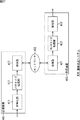
図1において、画像符号化装置100は、画像ライン入力部101、ラインバッファ部102、ウェーブレット変換部103、係数ライン並び替え部104、量子化部105、エントロピ符号化部106、付加部107、およびレート制御部108を有する。
In FIG. 1, an image encoding device 100 includes an image line input unit 101, a
画像ライン入力部101は、入力される画像データ(矢印D10)を、ライン毎にラインバッファ部102に供給し(矢印D11)、ラインバッファ部102に蓄積させる。ラインバッファ部102は、画像ライン入力部101から供給される画像データや、ウェーブレット変換部103から供給される係数データを保持し、所定のタイミングにおいてその画像データや係数データをウェーブレット変換部103に供給する(矢印D12)。
The image line input unit 101 supplies the input image data (arrow D10) to the
ウェーブレット変換部103は、ラインバッファ部102から供給される画像データや係数データに対してウェーブレット変換を行い、次の階層の低域成分と高域成分の係数データを生成する。ウェーブレット変換の詳細については後述する。
The
ウェーブレット変換部103は、生成した係数データの、垂直方向および水平方向に低域な成分をラインバッファ部102に供給して保持させ(矢印D13)、その他の成分を係数ライン並び替え部104に供給する(矢印D14)。なお、ウェーブレット変換部103は、生成した係数データが最上位層である場合、垂直方向および水平方向に低域な成分も係数ライン並び替え部104に供給する。
The
係数ライン並び替え部104には、ウェーブレット変換部103から係数データ(係数ライン)が供給される(矢印D14)。係数ライン並び替え部104は、その係数データ(係数ライン)の順序を、ウェーブレット逆変換処理の順序に並び替える。
Coefficient data (coefficient lines) is supplied from the
図1に示されるように、係数ライン並び替え部104は、係数ライン並び替えバッファ111および係数ライン読み出し部112を有する。係数ライン並び替えバッファ111は、ウェーブレット変換部103から供給される係数ラインを保持する。係数ライン読み出し部112は、係数ライン並び替えバッファ111に保持された係数ラインを、ウェーブレット逆変換処理の順序で読み出す(矢印D15)ことにより、並び替えを行う。この並び替えの詳細については後述する。
As illustrated in FIG. 1, the coefficient
係数ライン並び替え部104(係数ライン読み出し部112)は、順序を並び替えた係数データを量子化部105に供給する(矢印D16)。 The coefficient line rearrangement unit 104 (coefficient line reading unit 112) supplies the coefficient data whose order has been rearranged to the quantization unit 105 (arrow D16).
量子化部105は、係数ライン並び替え部104から供給された係数データに対して、量子化を行う。この量子化の方法としてはどのようなものを用いても良く、例えば、一般的な手段、つまり、以下の式(1)に示されるような、係数データWを量子化ステップサイズQで除算する手法を用いれば良い。
The quantization unit 105 performs quantization on the coefficient data supplied from the coefficient
量子化係数=W/Q ・・・(1) Quantization coefficient = W / Q (1)
なお、この量子化ステップサイズQは、レート制御部108により指定される。量子化部105は、量子化された係数データをエントロピ符号化部106に供給する(矢印D17)。
The quantization step size Q is specified by the
エントロピ符号化部106は、量子化部105から供給される係数データを、例えばハフマン符号化や算術符号化といった所定のエントロピ符号化方式で符号化する。エントロピ符号化部106は、1係数ラインを符号化すると、その1係数ラインから生成された符号化データである1符号ラインを付加部107に供給する(矢印D18)。エントロピ符号化部106は、さらに、その1符号ラインの符号量を付加部107に供給する(点線矢印D19)。
The
付加部107は、エントロピ符号化部106から供給された1符号ラインに対して、同じくエントロピ符号化部106から供給されたその1符号ラインの符号量を、ヘッダ情報として付加する。ヘッダ情報の付加の詳細については後述する。ヘッダ情報を付加すると、付加部107は、その符号化データ(符号ライン)を画像符号化装置100の外部に出力する(矢印D20)。画像符号化装置100の外部に出力された符号化データは、例えばネットワーク等を介して、後述する画像復号装置に供給される。
The adding
この符号化データは、係数ライン並び替え部104により、ウェーブレット逆変換の順に並び替えられている。これにより、例えば、画像復号装置による復号処理の遅延時間を低減させることができる。
The encoded data is rearranged by the coefficient
なお、エントロピ符号化部106は、各符号ラインの符号量を、レート制御部108にも供給する(点線矢印D21)。
The
レート制御部108は、エントロピ符号化部106から供給される符号ライン毎の符号量に基づいて、画像の符号化難易度を推定し、その符号化難易度に応じて量子化部105により用いられる量子化ステップサイズQを指定する(点線矢印D22)。つまり、レート制御部108は、量子化ステップサイズQを指定することにより、符号化データのレート制御を行う。
The
[サブバンドの説明]
次に、画像符号化装置100が行うウェーブレット変換について説明する。ウェーブレット変換は、画像データを空間周波数の高い成分(高域成分)と低い成分(低域成分)とに分割する分析フィルタリングを、再帰的に繰り返すことにより、画像データを、階層的に構成される周波数成分毎の係数データに変換する処理である。なお、以下において、分割レベルは、高域成分の階層ほど下位とし、低域成分の階層ほど上位とする。
[Description of sub-band]
Next, wavelet transform performed by the image encoding device 100 will be described. In wavelet transform, image data is hierarchically constructed by recursively repeating analysis filtering that divides image data into high spatial frequency components (high frequency components) and low frequency components (low frequency components). This is a process of converting into coefficient data for each frequency component. In the following description, the division level is lower in the higher-frequency component hierarchy and higher in the lower-frequency component hierarchy.
1つの階層(分割レベル)において、分析フィルタリングは、水平方向と垂直方向の両方について行われる。最初に水平方向の分析フィルタリングが行われ、次に垂直方向の分析フィルタリングが行われる。したがって、1つの階層の係数データ(画像データ)は、1階層分の分析フィルタリングにより4つのサブバンド(LL、LH、HL、およびHH)に分割される。そして、次の階層の分析フィルタリングは、生成された4つのサブバンドのうち、水平方向および垂直方向の両方について低域な成分(LL)に対して行われる。 In one hierarchy (division level), analysis filtering is performed in both the horizontal and vertical directions. First, horizontal analysis filtering is performed, and then vertical analysis filtering is performed. Therefore, coefficient data (image data) of one layer is divided into four subbands (LL, LH, HL, and HH) by analysis filtering for one layer. The analysis filtering of the next layer is performed on the low frequency component (LL) in both the horizontal direction and the vertical direction among the generated four subbands.
このように分析フィルタリングを再帰的に繰り返すことにより、空間周波数の低い帯域の係数データをより小さな領域に追い込むことができる。したがって、このようにウェーブレット変換された係数データを符号化するようにすることにより、効率的な符号化が可能となる。 As described above, the analysis filtering is recursively repeated, so that the coefficient data in the low spatial frequency band can be driven into a smaller area. Therefore, efficient encoding is possible by encoding the coefficient data subjected to wavelet transform in this way.
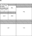
図2は、分析フィルタリングを4回繰り返して生成される係数データの構成について説明する図である。 FIG. 2 is a diagram illustrating the configuration of coefficient data generated by repeating analysis filtering four times.
ベースバンドの画像データに対して分割レベル1の分析フィルタリングが行われると、画像データは、分割レベル1の4つのサブバンド(1LL、1LH、1HL、および1HH)に変換される。この分割レベル1の、水平方向および垂直方向の両方に対して低域成分のサブバンド1LLに対して、分割レベル2の分析フィルタリングが行われ、分割レベル2の4つのサブバンド(2LL、2LH、2HL、および2HH)に変換される。この分割レベル2の、水平方向および垂直方向の両方に対して低域成分のサブバンド2LLに対して、分割レベル3の分析フィルタリングが行われ、分割レベル3の4つのサブバンド(3LL、3LH、3HL、および3HH)に変換される。この分割レベル3の、水平方向および垂直方向の両方に対して低域成分のサブバンド3LLに対して、分割レベル4の分析フィルタリングが行われ、分割レベル4の4つのサブバンド(4LL、4LH、4HL、および4HH)に変換される。
When analysis filtering at
図2は、このようにして、13個のサブバンドに分割された係数データの構成を示している。 FIG. 2 shows the configuration of coefficient data divided into 13 subbands in this way.
以上のような分析フィルタリングにより、処理対象となる2ラインの画像データまたは係数データから、1階層上の4つのサブバンドの係数データが1ラインずつ生成される。したがって、図2の斜線部分で示されるように、分割レベル4のサブバンドの係数データが1ラインずつ生成されるのに、サブバンド3LLは2ライン必要であり、サブバンド2LLは4ライン必要であり、サブバンド1LLは8ライン必要である。つまり、16ラインの画像データが必要になる。
By the analysis filtering as described above, coefficient data of four subbands on one layer is generated line by line from two lines of image data or coefficient data to be processed. Therefore, as indicated by the hatched portion in FIG. 2, subline 3LL requires 2 lines and subband 2LL requires 4 lines in order to generate the
このような最低域成分のサブバンドの1ライン分の係数データを生成するために必要なライン数の画像データをラインブロック(またはプレシンクト)と称する。また、ラインブロックは、その1ラインブロックの画像データをウェーブレット変換して得られる各サブバンドの係数データの集合のことも示す。 Such image data having the number of lines necessary to generate coefficient data for one line of the subband of the lowest band component is referred to as a line block (or precinct). The line block also indicates a set of coefficient data of each subband obtained by wavelet transforming the image data of the one line block.
例えば、図2の例の場合、図示せぬ16ラインの画像データが1ラインブロックとなる。また、ラインブロックは、その16ラインの画像データから生成される、分割レベル1の各サブバンドの8ラインの係数データ、分割レベル2の各サブバンドの4ラインの係数データ、分割レベル3の各サブバンドの2ラインの係数データ、および分割レベル4の各サブバンドの1ラインの係数データのことを示す場合もある。
For example, in the case of the example in FIG. 2, 16 lines of image data (not shown) form one line block. The line block is generated from the 16 lines of image data, the coefficient data of 8 lines of each subband of
ウェーブレット変換部103は、ウェーブレット変換をこのようなラインブロック毎に行うとも言える。
It can be said that the
ここでラインとは、ウェーブレット変換前の画像データに対応するピクチャ若しくはフィールド内、各分割レベル内、または各サブバンド内において形成される1行のことを示す。 Here, the line indicates one row formed in a picture or field corresponding to image data before wavelet transform, in each division level, or in each subband.
この1ライン分の係数データ(画像データ)を係数ラインとも称する。より詳細に区別して説明する必要がある場合、適宜表現を変える。例えば、あるサブバンドのある1ラインを「あるサブバンドの係数ライン」と称し、1つ下位の階層の同じ2係数ラインから生成された、ある階層(分割レベル)の全サブバンド(LH,HL、およびHH(最上位層の場合LLも含む))の1ラインを「ある分割レベル(または階層)の係数ライン」と称する。 The coefficient data (image data) for one line is also referred to as a coefficient line. When it is necessary to distinguish and explain in more detail, the expression is changed as appropriate. For example, a certain line of a certain subband is referred to as a “coefficient line of a certain subband”, and all subbands (LH, HL) of a certain hierarchy (division level) generated from the same two coefficient lines of the hierarchy one level lower. , And HH (including LL in the case of the highest layer)) are called “coefficient lines of a certain division level (or hierarchy)”.
図2の例の場合、「分割レベル4(最上位層)の係数ライン」は、サブバンド4LL,4LH,4HL、および4HHの、互いに対応する(1つ下位の分割レベルの同じ係数ラインから生成された)ある1ラインを示す。また、「分割レベル3の係数ライン」は、サブバンド3LH,3HL、および3HHの、互いに対応するある1ラインを示す。さらに、「サブバンド2HHの係数ライン」は、サブバンド2HHのある1ラインを示す。
In the case of the example in FIG. 2, “division level 4 (highest layer) coefficient line” is generated from subbands 4LL, 4LH, 4HL, and 4HH that correspond to each other (the same coefficient line at the lower division level). One line). The “
なお、1係数ライン(1ライン分の係数データ)が符号化された1ライン分の符号化データを符号ラインとも称する。 Note that encoded data for one line obtained by encoding one coefficient line (coefficient data for one line) is also referred to as a code line.
図2においては、分割レベル4のウェーブレット変換について説明した。以下においても、基本的に、ウェーブレット変換は分割レベル4まで行われるものとして説明するが、実際には、ウェーブレット変換の階層数(分割レベル)は任意である。
In FIG. 2, the
[リフティング演算]
ウェーブレット変換部103は、通常、低域フィルタと高域フィルタとから構成されるフィルタバンクを用いて、上述のような処理を行う。なお、デジタルフィルタは、通常、複数タップ長のインパルス応答すなわちフィルタ係数を持っているため、フィルタ処理を行えるだけの入力画像データまたは係数データを予めバッファリングしておく必要がある。また、ウェーブレット変換を多段にわたって行う場合も同様に、前段で生成したウェーブレット変換係数を、フィルタ処理が行える数だけバッファリングしておく必要がある。
[Lifting calculation]
The
このウェーブレット変換の具体的な例として、5×3フィルタを用いる方法について説明する。この5×3フィルタを用いる方法は、従来技術で既に説明したJPEG(Joint Photographic Experts Group)2000規格でも採用されており、少ないフィルタタップ数でウェーブレット変換を行うことができる点で、優れた方法である。 As a specific example of this wavelet transform, a method using a 5 × 3 filter will be described. This 5 × 3 filter method is also adopted in the JPEG (Joint Photographic Experts Group) 2000 standard already described in the prior art, and is an excellent method in that wavelet transform can be performed with a small number of filter taps. is there.
5×3フィルタのインパルス応答(Z変換表現)は、次の式(2)および式(3)に示すように、低域フィルタH 0 (z)と、高域フィルタH1(z)とから構成される。式(2)および式(3)から、低域フィルタH0(z)は、5タップで、高域フィルタH1(z)は、3タップであることが分かる。 The impulse response (Z conversion expression) of the 5 × 3 filter is obtained from the low-pass filter H 0 (z) and the high-pass filter H 1 (z) as shown in the following equations (2) and (3). Composed. From the equations (2) and (3), it can be seen that the low-pass filter H 0 (z) is 5 taps and the high-pass filter H 1 (z) is 3 taps.
H0(z)=(−1+2z-1+6z-2+2z-3−z-4)/8 ・・・(2)
H1(z)=(−1+2z-1−z-2)/2 ・・・(3)
H 0 (z) = (− 1 + 2z −1 + 6z −2 + 2z −3 −z −4 ) / 8 (2)
H 1 (z) = (− 1 + 2z −1 −z −2 ) / 2 (3)
これら式(2)および式(3)によれば、低域成分および高域成分の係数を、直接的に算出することができる。ここで、リフティング(Lifting)技術を用いることで、フィルタ処理の計算を減らすことができる。 According to these equations (2) and (3), the coefficients of the low frequency component and the high frequency component can be directly calculated. Here, the calculation of filter processing can be reduced by using a lifting technique.
図3は、5×3フィルタをリフティング表現した図である。図中、最上部の一列が入力信号列である。データ処理は画面上から下方向に流れ、以下の式(4)および式(5)により、高域成分の係数(高域係数)と、低域成分の係数(低域係数)とが出力される。 FIG. 3 is a diagram showing a lifting representation of a 5 × 3 filter. In the figure, the uppermost row is an input signal row. Data processing flows downward from the top of the screen, and the coefficient of the high frequency component (high frequency coefficient) and the coefficient of the low frequency component (low frequency coefficient) are output by the following equations (4) and (5). The
di 1=di 0−1/2(si 0+si+1 0) ・・・(4)
si 1=si 0+1/4(di-1 1+di 1) ・・・(5)
d i 1 = d i 0 −1/2 (s i 0 + s i + 1 0 ) (4)
s i 1 = s i 0 +1/4 (d i-1 1 + d i 1 ) (5)
図4は、5x3分析フィルタを用いて、縦方向のラインに対してフィルタリングを行った場合の図である。横方向は、演算過程とそれによって生成される低域・高域係数を図示したものである。図3の場合と照らし合わせて見れば水平が垂直に変わっただけであり、演算の方法は全く同様であることがわかる。 FIG. 4 is a diagram when filtering is performed on a vertical line using a 5 × 3 analysis filter. The horizontal direction shows the calculation process and the low-frequency and high-frequency coefficients generated thereby. In comparison with the case of FIG. 3, it can be seen that only the horizontal has changed to vertical, and the calculation method is exactly the same.
画像の上端においては、矢印151に示されるように、Line-1から最上位ラインが点線の様に対称拡張され、1ラインが補填される。枠152で示されるように、これとLine-0、Line-1の合計3ラインを用いてリフティング演算が行われ、Step-1の演算で係数aが生成される。これは高域係数(H0)である。
At the upper end of the image, as indicated by an
Line-1,Line-2,Line-3が入力されると、この3ラインを用いて次の高域係数aが算出される。これは高域係数(H1)である。そして、上記の1番目の高域係数a(H0)と2番目高域係数a(H1)、及びLine-1の係数の合計3つの係数を用いて、式2に従い計算すると係数bが生成される。これは低域係数(L1)である。つまり、枠153で示されるように、Line-1,Line-2,Line-3の3ラインと、高域係数(H0)とを用いて、低域係数(L1)および高域係数(H1)が生成される。
When Line-1, Line-2, and Line-3 are input, the next high frequency coefficient a is calculated using these three lines. This is a high frequency coefficient (H1). Then, using the first three high frequency coefficients a (H0), the second high frequency coefficient a (H1), and the line-1 coefficient in total, the coefficient b is generated by calculating according to
その後、2ラインが入力される毎に、上記のリフティング演算が後続のラインに対しても同様に繰り返され、低域係数と高域係数とが出力される。そして、枠154に示されるように、低域係数(L(N−1))および高域係数(H(N−1))が生成されると、高域係数(H(N−1))が矢印155のように対称拡張され、枠156のように演算が行われ、低域成分(L(N))が生成される。
Thereafter, each time two lines are input, the above-described lifting operation is repeated for the subsequent lines in the same manner, and a low frequency coefficient and a high frequency coefficient are output. Then, as shown in a
以上のリフティング演算は、各階層について再帰的に行われる。 The above lifting operation is performed recursively for each layer.
また図4は垂直方向のラインに対してフィルタリングを行った例であるが、水平方向のフィルタリングの場合でも全く同様に考えることができることは自明である。 Further, FIG. 4 shows an example in which filtering is performed on a vertical line, but it is obvious that the same can be considered in the case of horizontal filtering.
[分析フィルタリングの手順]
以上のような分析フィルタリングは、図5乃至図8のように進められる。
[Analysis filtering procedure]
The analysis filtering as described above proceeds as shown in FIGS.
すなわち、図5の左に示されるようにベースバンドの画像データが3ライン入力されると、図4を参照して説明したようにリフティング演算が行われ、図5の右に示されるように、分割レベル1の各サブバンド(1LL,1LH,1HL,1HH)が1ラインずつ生成される。
That is, when 3 lines of baseband image data are input as shown on the left of FIG. 5, a lifting operation is performed as described with reference to FIG. 4, and as shown on the right of FIG. Each subband (1LL, 1LH, 1HL, 1HH) of
その後、ベースバンドの画像データが2ライン入力される毎に、同様のリフティング演算が行われるので、図6の左に示されるように、ベースバンドの画像データ7ラインから、図6の右に示されるように、分割レベル1の各サブバンドの係数ラインが3ラインずつ生成される。
After that, every time two lines of baseband image data are input, the same lifting operation is performed. Therefore, as shown on the left side of FIG. 6, from the 7 lines of baseband image data, it is shown on the right side of FIG. As shown, three coefficient lines are generated for each subband at the
図7の左(図6の右)に示されるように、1LLの係数ラインが3ライン生成されると、図4を参照して説明したようにリフティング演算が行われ、図7の右に示されるように、分割レベル2の各サブバンド(2LL,2LH,2HL,2HH)が1ラインずつ生成される。分割レベル1においてもベースバンドのときと同様に、その後は1LLの係数ラインが2ラインずつ生成される毎にリフティング演算が行われ、分割レベル2の各サブバンドの係数ラインが1ラインずつ生成される。
As shown on the left of FIG. 7 (right of FIG. 6), when three 1LL coefficient lines are generated, a lifting operation is performed as described with reference to FIG. As shown, each subband (2LL, 2LH, 2HL, 2HH) at the
したがって、図8の左に示されるように、ベースバンドの画像データが11ラインから、図8の右に示されるように、分割レベル2の各サブバンドの係数ラインが2ラインと、分割レベル1の1LH,1HL、および1HHの各サブバンドの係数ラインが5ラインずつ生成される。 Therefore, as shown on the left of FIG. 8, the baseband image data is from 11 lines, and as shown on the right of FIG. Five coefficient lines are generated for each of the 1LH, 1HL, and 1HH subbands.
つまり、その時点で実行可能な、もっとも上位の階層のリフティング演算が実行される。換言すれば、より上位の階層のリフティング演算が優先的に実行される。また、分析フィルタリングは、画像上端の初期状態においては、3ラインの画像データ若しくは係数データが入力として必要である。ただし、それ以外の部分の定常状態においては、2ラインの画像データ若しくは係数データが入力される毎に分析フィルタリングが行われる。 That is, the lifting operation of the highest hierarchy that can be executed at that time is executed. In other words, the higher-level lifting operation is preferentially executed. The analysis filtering requires three lines of image data or coefficient data as input in the initial state at the upper end of the image. However, in the steady state of the other portions, analysis filtering is performed every time two lines of image data or coefficient data are input.
以上のような手順でリフティング演算は進行される。 The lifting operation proceeds in the above procedure.
[ウェーブレット変換部103の出力]
次に、以上のような手順で分析フィルタリングを行うウェーブレット変換部103から出力されるデータについて説明する。図9は、初期状態において、ウェーブレット変換部103から出力されるデータを時系列順に示す図である。図9においては、ウェーブレット変換部103から出力されるデータが、図中、上から下に向かう方向に時系列順に並べられている。
[Output of wavelet transform unit 103]
Next, data output from the
ウェーブレット変換部103が上述したような手順で分析フィルタリングを行うので、初期状態において、分割レベル1(サブバンド1HH,1HL、および1LH)の上から1番目の係数ライン(ライン1)が、ウェーブレット変換部103から出力され、係数ライン並び替え部104に供給される。サブバンド1LLのライン1は、ラインバッファ部102に供給され保持される。
Since the
続いて、分割レベル1のライン2(上から2番目の係数ライン)およびライン3(上から3番目の係数ライン)が、生成され次第、順次、係数ライン並び替え部104に供給される。サブバンド1LLのライン2とライン3は、ラインバッファ部102に供給され保持される。
Subsequently, the line 2 (second coefficient line from the top) and the line 3 (third coefficient line from the top) at the
上述したように、ウェーブレット変換部103は、ラインバッファ部102にサブバンド1LLの係数ラインが3ライン(2回目以降は2ライン)保持されると、それらに対して分割レベル1の分析フィルタリングを行う。
As described above, when the
したがって、分割レベル1のライン3が出力された後、分割レベル2(サブバンド2HH,2HL、および2LH)のライン1がウェーブレット変換部103から出力され、係数ライン並び替え部104に供給される。また、サブバンド2LLのライン1は、ラインバッファ部102に供給され保持される。
Therefore, after
続いて、分割レベル1のライン4(上から4番目の係数ライン)およびライン5(上から5番目の係数ライン)が、この順に生成され、順次、係数ライン並び替え部104に供給される。サブバンド1LLのライン4とライン5は、ラインバッファ部102に供給され保持される。
Subsequently, line 4 (fourth coefficient line from the top) and line 5 (fifth coefficient line from the top) at
ラインバッファ部102にサブバンド1LLの係数ラインが2ライン保持されたので、それらに対して分割レベル1の分析フィルタリングが行われ、分割レベル2のライン2がウェーブレット変換部103から出力され、係数ライン並び替え部104に供給される。また、サブバンド2LLのライン2は、ラインバッファ部102に供給され保持される。
Since the
続いて、分割レベル1のライン6(上から6番目の係数ライン)およびライン7(上から7番目の係数ライン)が、この順に生成され、順次、係数ライン並び替え部104に供給される。サブバンド1LLのライン6とライン7は、ラインバッファ部102に供給され保持される。
Subsequently, a
ラインバッファ部102にサブバンド1LLの係数ラインが2ライン保持されたので、それらに対して分割レベル1の分析フィルタリングが行われ、分割レベル2のライン3がウェーブレット変換部103から出力され、係数ライン並び替え部104に供給される。また、サブバンド2LLのライン3は、ラインバッファ部102に供給され保持される。
Since two lines of coefficient lines of subband 1LL are held in the
ラインバッファ部102にサブバンド2LLの係数ラインが3ライン(2回目以降は2ライン)保持されたので、それらに対して分割レベル2の分析フィルタリングが行われ、分割レベル3(サブバンド3HH,3HL、および3LH)のライン1がウェーブレット変換部103から出力され、係数ライン並び替え部104に供給される。また、サブバンド3LLのライン1は、ラインバッファ部102に供給され保持される。
Since the coefficient lines of the subband 2LL are held in the line buffer unit 102 (2 lines after the second time),
続いて、分割レベル1のライン8(上から8番目の係数ライン)およびライン9(上から9番目の係数ライン)が、この順に生成され、順次、係数ライン並び替え部104に供給される。サブバンド1LLのライン8とライン9は、ラインバッファ部102に供給され保持される。
Subsequently, the
ラインバッファ部102にサブバンド1LLの係数ラインが2ライン保持されると、それらに対して分割レベル1の分析フィルタリングが行われ、分割レベル2のライン4がウェーブレット変換部103から出力され、係数ライン並び替え部104に供給される。また、サブバンド2LLのライン4は、ラインバッファ部102に供給され保持される。
When two coefficient lines of the subband 1LL are held in the
続いて、分割レベル1のライン10(上から10番目の係数ライン)およびライン11(上から11番目の係数ライン)が、この順に生成され、順次、係数ライン並び替え部104に供給される。サブバンド1LLのライン10とライン11は、ラインバッファ部102に供給され保持される。
Subsequently, the
ラインバッファ部102にサブバンド1LLの係数ラインが2ライン保持されると、それらに対して分割レベル1の分析フィルタリングが行われ、分割レベル2のライン5がウェーブレット変換部103から出力され、係数ライン並び替え部104に供給される。また、サブバンド2LLのライン5は、ラインバッファ部102に供給され保持される。
When two coefficient lines of the subband 1LL are held in the
ラインバッファ部102にサブバンド2LLの係数ラインが2ライン保持されると、それらに対して分割レベル2の分析フィルタリングが行われ、分割レベル3のライン2がウェーブレット変換部103から出力され、係数ライン並び替え部104に供給される。また、サブバンド3LLのライン2は、ラインバッファ部102に供給され保持される。
When two coefficient lines of the subband 2LL are held in the
続いて、分割レベル1のライン12(上から12番目の係数ライン)およびライン13(上から13番目の係数ライン)が、この順に生成され、順次、係数ライン並び替え部104に供給される。サブバンド1LLのライン12とライン13は、ラインバッファ部102に供給され保持される。
Subsequently, the
ラインバッファ部102にサブバンド1LLの係数ラインが2ライン保持されると、それらに対して分割レベル1の分析フィルタリングが行われ、分割レベル2のライン6がウェーブレット変換部103から出力され、係数ライン並び替え部104に供給される。また、サブバンド2LLのライン6は、ラインバッファ部102に供給され保持される。
When two coefficient lines of the subband 1LL are held in the
続いて、分割レベル1のライン14(上から14番目の係数ライン)およびライン15(上から15番目の係数ライン)が、この順に生成され、順次、係数ライン並び替え部104に供給される。サブバンド1LLのライン14とライン15は、ラインバッファ部102に供給され保持される。
Subsequently, the
ラインバッファ部102にサブバンド1LLの係数ラインが2ライン保持されると、それらに対して分割レベル1の分析フィルタリングが行われ、分割レベル2のライン7がウェーブレット変換部103から出力され、係数ライン並び替え部104に供給される。また、サブバンド2LLのライン7は、ラインバッファ部102に供給され保持される。
When two coefficient lines of subband 1LL are held in the
ラインバッファ部102にサブバンド2LLの係数ラインが2ライン保持されると、それらに対して分割レベル2の分析フィルタリングが行われ、分割レベル3のライン3がウェーブレット変換部103から出力され、係数ライン並び替え部104に供給される。また、サブバンド3LLのライン3は、ラインバッファ部102に供給され保持される。
When two coefficient lines of subband 2LL are held in the
ラインバッファ部102にサブバンド3LLの係数ラインが3ライン(2回目以降は2ライン)保持されると、それらに対して分割レベル3の分析フィルタリングが行われ、分割レベル4(4HH,4HL,4LH、および4HH)のライン1がウェーブレット変換部103から出力され、係数ライン並び替え部104に供給される。
If the coefficient lines of the subband 3LL are held in the line buffer unit 102 (3 lines after the second time),
以上が、初期状態においてウェーブレット変換部103から出力される1ラインブロック分の係数ライン群である。初期状態が終了すると、2ラインずつ処理される定常状態に移行する。
The above is the coefficient line group for one line block output from the
図10は、定常状態において、ウェーブレット変換部103から出力されるデータを時系列順に示す図である。図10においては、図9と同様に、ウェーブレット変換部103から出力されるデータが、図中、上から下に向かう方向に時系列順に並べられている。
FIG. 10 is a diagram illustrating data output from the
ウェーブレット変換部103が上述したような手順で分析フィルタリングを行うので、定常状態のあるタイミングにおいて、分割レベル1のラインL(上からL番目の係数ライン)およびライン(L+1)(上から(L+1)番目の係数ライン)が、生成され次第、順次、ウェーブレット変換部103から出力され、係数ライン並び替え部104に供給される。サブバンド1LLのラインLおよびライン(L+1)は、ラインバッファ部102に供給され保持される。
Since the
ラインバッファ部102にサブバンド1LLの係数ラインが2ライン保持されると、それらに対して分割レベル1の分析フィルタリングが行われ、分割レベル2のラインM(上からM番目の係数ライン)がウェーブレット変換部103から出力され、係数ライン並び替え部104に供給される。また、サブバンド2LLのラインMは、ラインバッファ部102に供給され保持される。
When two coefficient lines of the subband 1LL are held in the
続いて、分割レベル1のライン(L+2)(上から(L+2)番目の係数ライン)およびライン(L+3)(上から(L+3)番目の係数ライン)が、この順に生成され、順次、係数ライン並び替え部104に供給される。サブバンド1LLのライン(L+2)とライン(L+3)は、ラインバッファ部102に供給され保持される。
Subsequently, a
ラインバッファ部102にサブバンド1LLの係数ラインが2ライン保持されると、それらに対して分割レベル1の分析フィルタリングが行われ、分割レベル2のライン(M+1)(上から(M+1)番目の係数ライン)がウェーブレット変換部103から出力され、係数ライン並び替え部104に供給される。また、サブバンド2LLのライン(M+1)は、ラインバッファ部102に供給され保持される。
If two coefficient lines of the subband 1LL are held in the
ラインバッファ部102にサブバンド2LLの係数ラインが2ライン保持されると、それらに対して分割レベル2の分析フィルタリングが行われ、分割レベル3のラインN(上からN番目の係数ライン)がウェーブレット変換部103から出力され、係数ライン並び替え部104に供給される。また、サブバンド3LLのラインNは、ラインバッファ部102に供給され保持される。
When two coefficient lines of the subband 2LL are held in the
続いて、分割レベル1のライン(L+4)(上から(L+4)番目の係数ライン)およびライン(L+5)(上から(L+5)番目の係数ライン)が、この順に生成され、順次、係数ライン並び替え部104に供給される。サブバンド1LLのライン(L+4)とライン(L+5)は、ラインバッファ部102に供給され保持される。
Subsequently, a
ラインバッファ部102にサブバンド1LLの係数ラインが2ライン保持されると、それらに対して分割レベル1の分析フィルタリングが行われ、分割レベル2のライン(M+2)(上から(M+2)番目の係数ライン)がウェーブレット変換部103から出力され、係数ライン並び替え部104に供給される。また、サブバンド2LLのライン(M+2)は、ラインバッファ部102に供給され保持される。
When two coefficient lines of the subband 1LL are held in the
続いて、分割レベル1のライン(L+6)(上から(L+6)番目の係数ライン)およびライン(L+7)(上から(L+7)番目の係数ライン)が、この順に生成され、順次、係数ライン並び替え部104に供給される。サブバンド1LLのライン(L+6)とライン(L+7)は、ラインバッファ部102に供給され保持される。
Subsequently, the
ラインバッファ部102にサブバンド1LLの係数ラインが2ライン保持されると、それらに対して分割レベル1の分析フィルタリングが行われ、分割レベル2のライン(M+3)(上から(M+3)番目の係数ライン)がウェーブレット変換部103から出力され、係数ライン並び替え部104に供給される。また、サブバンド2LLのライン(M+3)は、ラインバッファ部102に供給され保持される。
When two coefficient lines of the subband 1LL are held in the
ラインバッファ部102にサブバンド2LLの係数ラインが2ライン保持されると、それらに対して分割レベル2の分析フィルタリングが行われ、分割レベル3のライン(N+1)(上から(N+1)番目の係数ライン)がウェーブレット変換部103から出力され、係数ライン並び替え部104に供給される。また、サブバンド3LLのライン(N+1)は、ラインバッファ部102に供給され保持される。
When two coefficient lines of the subband 2LL are held in the
ラインバッファ部102にサブバンド3LLの係数ラインが2ライン保持されると、それらに対して分割レベル3の分析フィルタリングが行われ、分割レベル4のラインP(上からP番目の係数ライン)がウェーブレット変換部103から出力され、係数ライン並び替え部104に供給される。
If two line lines of subband 3LL are held in the
以上のような定常状態において、一番下のラインまで処理される。 In the steady state as described above, processing is performed up to the bottom line.
なお、ウェーブレット変換部103の各係数ラインの処理順、すなわち、ウェーブレット変換部103からの各係数ラインの出力順は、任意であり、上述した以外の順序であってもよい。ただし、上述したような手順で分析フィルタリングを行うことにより、ウェーブレット変換部103は、効率よく各係数ラインを生成することができ、低遅延に変換処理を行うことができる。
Note that the processing order of the coefficient lines of the
[係数ライン並び替え]
図9および図10を参照して説明したような順でウェーブレット変換部103から出力された各分割レベルの係数ラインは、係数ライン並び替え部104の係数ライン並び替えバッファ111に保持される。係数ラインが1ラインブロック分蓄積されると、係数ライン読み出し部112は、各係数ラインを、図11に示されるように、ウェーブレット逆変換処理の順序で読み出すことにより、係数ラインの並び替えを行う。
[Reorder coefficient lines]
The coefficient lines of each division level output from the
図11において、各係数ラインは、その処理順に並べられている。図中上から下に向かう向きに時系列が示されている。つまり、図11に示される各係数ラインは、図中上から順に処理される。 In FIG. 11, the coefficient lines are arranged in the processing order. A time series is shown from the top to the bottom in the figure. That is, each coefficient line shown in FIG. 11 is processed in order from the top in the figure.
つまり、図11の左側に示されるような順序(ウェーブレット変換出力順)でウェーブレット変換部103から出力された各係数ラインは、係数ライン並び替え部104により、図11の右側に示されるようなウェーブレット逆変換処理の順に並び替えられる。
That is, each coefficient line output from the
より具体的には、係数ライン読み出し部112は、分割レベル4のラインPの係数ラインを読み出し、分割レベル3のラインNの係数ラインを読み出し、分割レベル2のラインMの係数ラインを読み出し、分割レベル1のラインLおよびライン(L+1)の係数ラインを読み出し、読み出した各係数ラインを、その読み出し順に量子化部105に供給する。
More specifically, the coefficient
また、係数ライン読み出し部112は、次に、分割レベル2のライン(M+1)の係数ラインを読み出し、分割レベル1のライン(L+2)およびライン(L+3)の係数ラインを読み出し、読み出した各係数ラインを、その読み出し順に量子化部105に供給する。
Next, the coefficient
さらに、係数ライン読み出し部112は、分割レベル3のライン(N+1)の係数ラインを読み出し、分割レベル2のライン(M+2)の係数ラインを読み出し、分割レベル1のライン(L+4)およびライン(L+5)の係数ラインを読み出し、読み出した各係数ラインを、その読み出し順に量子化部105に供給する。
Further, the coefficient
また、係数ライン読み出し部112は、次に、分割レベル2のライン(M+3)の係数ラインを読み出し、分割レベル1のライン(L+6)およびライン(L+7)の係数ラインを読み出し、読み出した各係数ラインを、その読み出し順に量子化部105に供給する。
Next, the coefficient
量子化部105は、各係数ラインを、供給された順に処理し、エントロピ符号化部106に供給するので、エントロピ符号化部106も、この図11の左に示される順に、各係数ラインを処理することになる。
Since the quantization unit 105 processes each coefficient line in the supplied order and supplies it to the
レート制御部108は、係数値が小さければ量子化ステップサイズを小さくするように設定して符号量発生を促進し、係数値が大きければステップサイズを大きくするように設定して符号量の発生を抑制するなどの制御を行う。
The
なお、係数ラインの並び替えは、画像符号化装置100の中で行われればよく、例えば、量子化処理の後に行うようにしてもよい。 Note that the rearrangement of coefficient lines only needs to be performed in the image encoding apparatus 100, and may be performed after the quantization process, for example.
[符号量の付加]
上述したように、付加部107は、各符号ラインに対して、その符号ラインの符号量を、ヘッダ情報として付加する。図12にその様子の例を示す。
[Add code amount]
As described above, the adding
図12の例において、付加部107は、各分割レベルの符号ライン(符号語)に対して、その符号量をヘッダ情報(Code_info)として付加している。例えば、分割レベル1の符号ライン(ラインL)の符号量が100バイトの場合、その符号ライン(ラインL)の例えば先頭に、「100バイト」を示す情報が、ヘッダ情報(Code_info(L))として付加される。
In the example of FIG. 12, the adding
上述したように、画像符号化装置100の各部は、係数データを係数ライン毎に取り扱う。すなわち、各部は、係数ラインの境界を把握することができる。しかしながら、画像符号化装置100により生成された符号化データを復号する画像復号装置には、各符号ラインが連続して供給されるので、その符号ラインの境界を把握することができない。 As described above, each unit of the image encoding device 100 handles coefficient data for each coefficient line. That is, each unit can grasp the boundary of the coefficient line. However, since each code line is continuously supplied to the image decoding apparatus that decodes the encoded data generated by the image encoding apparatus 100, the boundary between the code lines cannot be grasped.
そこで、付加部107が各符号ラインの符号量を符号化データに付加することにより、画像復号装置は、その符号量に基づいて、符号化データ(ストリーム)を符号ライン毎に分割し、処理することができるようになる。
Therefore, the adding
[処理の流れ]
以上のような画像符号化装置100の各部により実行される符号化処理の流れの例を、図13のフローチャートを参照して説明する。なお、この符号化処理は、入力画像のピクチャ毎に実行される。
[Process flow]
An example of the flow of encoding processing executed by each unit of the image encoding device 100 as described above will be described with reference to the flowchart of FIG. This encoding process is executed for each picture of the input image.
符号化処理が開始されると、ステップS101において、画像ライン入力部101が、ライン毎に入力される画像データを受け付けながら(ラインバッファ部102に保持させながら)、ウェーブレット変換部103が、ラインバッファ部102に保持されている係数ラインを用いて、ウェーブレット変換を1ラインブロック分行う。
When the encoding process is started, in step S101, the image line input unit 101 receives the image data input for each line (while holding it in the line buffer unit 102), and the
ステップS102において、ウェーブレット変換部103は、1ラインブロック分の処理を行ったか否かを判定する。1ラインブロック分の処理を行っていないと判定された場合、ステップS101に戻り、ウェーブレット変換処理を継続する。
In step S102, the
1ラインブロック分ウェーブレット変換処理を行ったと判定された場合、ステップS103に進む。 If it is determined that the wavelet transform process has been performed for one line block, the process proceeds to step S103.
ステップS103において、係数ライン並び替え部104は、ウェーブレット変換された係数データを、ウェーブレット逆変換処理順に並び替える。ステップS104において、量子化部105は、その係数データを、レート制御部108に指定される量子化ステップサイズで量子化する。
In step S103, the coefficient
ステップS105において、エントロピ符号化部106は、係数データをエントロピ符号化する。ステップS106において、付加部107は、各符号ラインにその符号量をヘッダ情報として付加する。ステップS107において、付加部107は、ウェーブレット逆変換処理順に並び替えられた符号化データを出力する。
In step S105, the
ステップS108において、レート制御部108は、エントロピ符号化部106におけるエントロピ符号化の情報に基づいて、レート制御を行う。
In step S108, the
ステップS109において、ウェーブレット変換部103は、処理対象ピクチャの最終ラインブロック(例えば最下段のラインブロック)まで処理したか否かを判定する。処理していないと判定された場合、ステップS101に戻り、次のラインブロックに対して、それ以降の処理が繰り返される。また、ステップS110において、最終ラインブロックまで、処理が終了したと判定された場合、その処理対象ピクチャに対する符号化処理が終了される。
In step S109, the
[画像復号装置のデバイスの構成]
次に、上述した画像符号化装置100に対応する画像復号装置について説明する。図14は、本発明を適用した画像処理装置としての画像復号装置の一実施の形態の構成例を示すブロック図である。
[Device Configuration of Image Decoding Device]
Next, an image decoding apparatus corresponding to the above-described image encoding apparatus 100 will be described. FIG. 14 is a block diagram showing a configuration example of an embodiment of an image decoding apparatus as an image processing apparatus to which the present invention is applied.
画像復号装置200は、画像符号化装置100より出力される符号化データを復号し、復号画像を生成する。 The image decoding device 200 decodes the encoded data output from the image encoding device 100 and generates a decoded image.
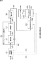
画像復号装置200は、符号語解読部201、サブバンド・ライン選択部202、エントロピ復号部203、逆量子化部204、ウェーブレット逆変換部205、およびバッファ部206を有する。
The image decoding apparatus 200 includes a
符号語解読部201は、入力された符号化データ(符号語)(矢印D51)を解読して、データや符号化処理に関する関連情報を抽出する。この関連情報にどのような情報が含まれていてもよいが、例えば、画像の解像度(水平・垂直サイズ)、量子化ステップサイズ、ウェーブレット変換の分解数、および係数ライン(符号ライン)の並び順に関する情報等が含まれる。
The
係数ライン(符号ライン)の並び順に関する情報としては、各分割レベルの符号ラインの並び順を示す情報、若しくは、その並び順を求めるのに必要な情報であればどのようなものであってもよい。例えば、図12に示されるような、各分割レベルの符号ラインの符号量を含むヘッダ情報や、後述するマーカの検出結果等であってもよい。 The information regarding the arrangement order of the coefficient lines (code lines) may be any information indicating the arrangement order of the code lines of each division level or information necessary for obtaining the arrangement order. Good. For example, as shown in FIG. 12, header information including the code amount of the code line at each division level, a marker detection result described later, and the like may be used.
符号語解読部201は、入力された符号化データ(コードストリーム)をサブバンド・ライン選択部202に供給する(矢印D52)。また、符号語解読部201は、コードストリームにおいて各分割レベルの符号ラインを区別するために必要な情報をサブバンド・ライン選択部202に供給する(点線矢印D62)。例えば、符号語解読部201は、各分割レベルの符号ラインの符号量や、マーカの検出結果等をサブバンド・ライン選択部202に供給する。
The
また、符号語解読部201は、量子化ステップサイズを示す情報を逆量子化部204に供給する(点線矢印D61)。
Also, the
符号語解読部201は、さらに、例えば画像の解像度やウェーブレット変換の分解数等の、ウェーブレット逆変換処理に必要な情報をウェーブレット逆変換部205に供給する(点線矢印D60)。
The
サブバンド・ライン選択部202は、符号語解読部201から供給される各分割レベルの符号ラインを区別するために必要な情報に基づいて、符号語解読部201から供給されるコードストリームから、復号する各分割レベルの符号ラインを選択する。
The subband
画像復号装置200は、画像符号化装置100から供給される符号化データを復号して復号画像を生成する。この画像符号化装置100より供給される符号化データは、ウェーブレット変換により複数の周波数帯域に分割された係数データをエントロピ符号化したものである。この係数データのサブバンドは、図2を参照して説明したように階層化されており、その時点で最低域成分となるサブバンド(図2の例の場合、4LL)には、画像のエネルギーのほとんどが集中しており、元の画像と略同等とみなすことができる(画像データとして成立する)。ただし、上位階層(低域成分)になる程、その解像度は小さくなる。 The image decoding device 200 decodes the encoded data supplied from the image encoding device 100 to generate a decoded image. The encoded data supplied from the image encoding apparatus 100 is obtained by entropy encoding coefficient data divided into a plurality of frequency bands by wavelet transform. The subbands of the coefficient data are hierarchized as described with reference to FIG. 2, and the energy of the image is included in the subband (4LL in the example of FIG. 2) that is the lowest band component at that time. Most of them are concentrated and can be regarded as substantially equivalent to the original image (established as image data). However, the higher the hierarchy (low frequency component), the smaller the resolution.
つまり、画像復号装置200は、このようなサブバンド毎に分割された係数データを、最上位の階層(最低域成分)から所望の階層までウェーブレット逆変換することにより、元の画像以下の解像度で復号画像を生成することができる。換言すれば、画像復号装置200は、ウェーブレット逆変換(合成フィルタリング)を行う階層を選択することにより、復元画像の解像度を選択することができる。すなわち、画像復号装置200は、符号化データをスケーラブルにデコードすることができる。 That is, the image decoding apparatus 200 performs inverse wavelet transform on the coefficient data divided for each subband from the highest layer (lowest band component) to a desired layer, thereby reducing the resolution of the original image or lower. A decoded image can be generated. In other words, the image decoding apparatus 200 can select the resolution of the restored image by selecting a layer for performing wavelet inverse transform (synthesis filtering). That is, the image decoding apparatus 200 can decode encoded data in a scalable manner.
このように、解像度の小さい復号画像を得るために、符号化データの一部のサブバンドのみを復号することを部分デコードと称する。なお、全てのサブバンドをデコード(フルデコード)した場合の復号画像の解像度は、元の画像の解像度と同一になる。 Thus, in order to obtain a decoded image with a small resolution, decoding only a part of the subbands of the encoded data is referred to as partial decoding. Note that the resolution of the decoded image when all subbands are decoded (full decoding) is the same as the resolution of the original image.
このような部分デコードを行う場合、合成フィルタリングされない高域成分のサブバンドは、不要であり、エントロピ復号する必要がない。したがって、サブバンド・ライン選択部202は、合成フィルタリングを行うサブバンドの係数データ(に対応する符号化データ)のみを選択し、不要なサブバンドの係数データ(に対応する符号化データ)を破棄する。サブバンド・ライン選択部202は、このような選択を、符号語解読部201から供給される情報に基づいて行う。
When such partial decoding is performed, subbands of high-frequency components that are not subjected to synthesis filtering are unnecessary, and there is no need to perform entropy decoding. Therefore, the subband /
サブバンド・ライン選択部202は、選択部211および保持部212を有する。符号語解読部201から出力された符号化データ(コードストリーム)は、選択部211に供給される。また、符号語解読部201から供給されるコードストリームにおいて各分割レベルの符号ラインを区別するために必要な情報も、選択部211に供給される。
The subband /
選択部211は、符号語解読部201から供給されるコードストリームにおいて各分割レベルの符号ラインを区別するために必要な情報に基づいて、符号語解読部201から供給されるコードストリームにおいて、各分割レベルの符号ラインを識別し、その分割レベルの符号ラインの取捨選択を行う。
The
復号画像の解像度は、予め設定されている。つまり、必要なデータと不要なデータは、予め定められている。したがって、選択部211は、その設定に従って、供給される符号ラインの一部または全部を選択することになる。
The resolution of the decoded image is set in advance. That is, necessary data and unnecessary data are determined in advance. Therefore, the
もちろん、例えばユーザ等が復号画像の解像度を適宜選択し、選択部211は、そのような解像度指定指示に従って、符号化する必要な符号ラインを特定し、供給される符号ラインの中からその特定した符号ラインを検索し、選択するようにしてもよい。
Of course, for example, the user or the like appropriately selects the resolution of the decoded image, and the
いずれにしても、この選択部211の選択により、必要な符号ラインが抽出されるのみであり、符号ラインの並びは変化しない。したがって、サブバンド・ライン選択部202は、ウェーブレット逆変換順に供給された各符号ラインを、そのウェーブレット逆変換順のまま、エントロピ復号部203に供給することができる。
In any case, only the necessary code lines are extracted by the selection of the
選択部211は、選択した符号ラインを保持部212に供給し、保持させる(矢印D53)。
The
保持部212は、選択部211から供給される符号ラインを保持し、所定のタイミングにおいて、その符号ラインをエントロピ復号部203に供給する(矢印D54)。なお、この保持部212を省略し、選択部211の出力がエントロピ復号部203に供給されるようにしてもよい。ただし、符号ラインの並び方によっては、選択部211により符号ラインが選択されるタイミングに偏りが生じる場合が考えられる。この保持部212を用いて選択された符号ラインをバッファリングすることにより、その偏りを低減させることができ、エントロピ復号部203の処理効率を向上させることができる。
The holding
エントロピ復号部203は、各分割レベルの符号ラインを、エントロピ符号化部106(図1)のエントロピ符号化に対応する方法で、エントロピ復号し、係数データ(量子化係数)を生成する。エントロピ復号部203は、その分割レベルの係数ライン(量子化係数)を逆量子化部204に供給する(矢印D55)。
The
逆量子化部204は、エントロピ復号部203から供給される、各分割レベルの係数ライン(量子化係数)を、符号語解読部201から供給される情報に基づいて決定される量子化ステップサイズにより逆量子化する。逆量子化部204は、逆量子化した各分割レベルの係数ライン(ウェーブレット変換係数)をウェーブレット逆変換部205に供給する(矢印D56)。
The
ウェーブレット逆変換部205は、符号語解読部201から供給される情報に基づいて、ウェーブレット変換部103(図1)において行われたウェーブレット変換の逆処理を行い、復号画像を生成する。ウェーブレット逆変換の詳細については後述する。
Based on the information supplied from the
ウェーブレット逆変換部205は、係数データの低域成分と高域成分を合成する合成フィルタリングを繰り返すことにより、ウェーブレット逆変換を行う。このとき、ウェーブレット逆変換部205は、合成フィルタリングを行って生成された1つ下位の階層の係数データを、バッファ部206に供給して保持させ(矢印D57)、次の合成フィルタリングに利用する。つまり、ウェーブレット逆変換部205は、逆量子化部204から供給される係数データ(矢印D56)の他に、必要に応じて、バッファ部206から読みだされた係数データ(矢印D58)も用いて合成フィルタリングを行う。
The wavelet
以上のように合成フィルタリングを繰り返し行い、復号画像を復元すると、ウェーブレット逆変換部205は、その画像データを画像復号装置200の外部に出力する(矢印D59)。
When the combined filtering is repeatedly performed as described above and the decoded image is restored, the wavelet
このように、画像復号装置200は、符号化データをスケーラブルにデコードすることができる。このとき、画像復号装置200は、ピクチャよりも小さい単位のラインブロックを単位としてデコードを行う。したがって、画像復号装置200は、符号化データを、低遅延に、かつ、スケーラブルにデコードすることができる。 As described above, the image decoding apparatus 200 can decode the encoded data in a scalable manner. At this time, the image decoding apparatus 200 performs decoding in units of line blocks that are smaller than a picture. Therefore, the image decoding apparatus 200 can decode the encoded data with low delay and in a scalable manner.
特に、このラインブロックは、最上位のサブバンドの係数ラインを少なくとも1ライン生成するのに必要なライン数の画像データであり、ウェーブレット変換可能な最小のデータ単位とすることもできる。したがって、画像復号装置200は、符号化データを、より低遅延に、かつ、スケーラブルにデコードすることができる。 In particular, this line block is image data of the number of lines necessary to generate at least one coefficient line of the highest subband, and can be a minimum data unit that can be wavelet transformed. Therefore, the image decoding apparatus 200 can decode encoded data with lower delay and in a scalable manner.
[部分デコード]
次に、部分デコードについて説明する。図15は、部分デコードの例を説明する図である。図15において、画像データは、ウェーブレット変換され、分割レベル4まで分割されている。
[Partial decoding]
Next, partial decoding will be described. FIG. 15 is a diagram for explaining an example of partial decoding. In FIG. 15, the image data is wavelet transformed and divided up to
例えば、復号画像の解像度を元の画像の解像度の4分の1とする場合、サブバンド1LLを復号画像とすればよい。したがって、点線枠で示されるように、分割レベル4乃至分割レベル2の係数データを合成フィルタリングすればよい。つまり、サブバンド1LH、1HL、および1HHの係数データは不要であるので、サブバンド・ライン選択部202は、これらの係数データに対応する符号ラインを選択しない。
For example, when the resolution of the decoded image is set to ¼ of the resolution of the original image, the subband 1LL may be used as the decoded image. Therefore, as shown by the dotted frame, the
このように、符号ラインが必要か否かは、生成する復号画像の解像度によって決まる。換言すれば、選択する符号ラインは、最下位階層からどの階層までをウェーブレット逆変換するかによって決まる。 Thus, whether or not a code line is necessary depends on the resolution of the decoded image to be generated. In other words, the code line to be selected is determined depending on which layer from the lowest layer to which wavelet is inversely transformed.
[スケーラブルデコードの例]
例えば、画像復号装置200が元の画像の1/16×1/16の解像度でデコードする場合、サブバンド・ライン選択部202は、図16Aに示されるケース1のように、分割レベル4(最下位階層)の最低域成分(サブバンド4LL)の係数ラインのみを選択する。
[Example of scalable decoding]
For example, when the image decoding apparatus 200 decodes at a resolution of 1/16 × 1/16 of the original image, the subband /
ウェーブレット変換やウェーブレット逆変換は、ラインブロック毎に行われるので、サブバンド・ライン選択部202の選択もラインブロック毎となる。したがって、ケース1の場合、図16Aに示されるように、サブバンド4LLの係数ライン(符号ライン)が1ライン(ラインP)選択される。
Since the wavelet transform and the inverse wavelet transform are performed for each line block, the selection of the subband /
また、例えば、画像復号装置200が元の画像の1/8×1/8の解像度でデコードする場合、サブバンド・ライン選択部202は、図16Bに示されるケース2のように、分割レベル4(最下位階層)の各サブバンド(4HH,4HL,4LH、および4LL)の係数ライン(ラインP)のみを選択する。
Also, for example, when the image decoding apparatus 200 decodes at a resolution of 1/8 × 1/8 of the original image, the subband /
さらに、例えば、画像復号装置200が元の画像の1/4×1/4の解像度でデコードする場合、サブバンド・ライン選択部202は、図16Cに示されるケース3のように、分割レベル4(最下位階層)の各サブバンド(4HH,4HL,4LH、および4LL)の係数ライン(ラインP)と、分割レベル3の各サブバンド(3HH,3HL、および3LH)の係数ライン(ラインNおよびライン(N+1))とを選択する。
Further, for example, when the image decoding apparatus 200 decodes at a resolution of ¼ × 1/4 of the original image, the subband /
また、例えば、画像復号装置200が元の画像の1/2×1/2の解像度でデコードする場合、サブバンド・ライン選択部202は、図16Dに示されるケース4のように、分割レベル4(最下位階層)の各サブバンド(4HH,4HL,4LH、および4LL)の係数ライン(ラインP)と、分割レベル3の各サブバンド(3HH,3HL、および3LH)の係数ライン(ラインNおよびライン(N+1))と、分割レベル2の各サブバンド(2HH,2HL、および2LH)の係数ライン(ラインM乃至ライン(M+3))とを選択する。
Also, for example, when the image decoding apparatus 200 decodes at a resolution of 1/2 × 1/2 of the original image, the subband /
さらに、例えば、画像復号装置200が元の画像と同じ解像度でデコードする場合、サブバンド・ライン選択部202は、図16Eに示されるケース5のように、全てのサブバンドの係数ライン(分割レベル4の各サブバンド(4HH,4HL,4LH、および4LL)の係数ライン(ラインP)と、分割レベル3の各サブバンド(3HH,3HL、および3LH)の係数ライン(ラインNおよびライン(N+1))と、分割レベル2の各サブバンド(2HH,2HL、および2LH)の係数ライン(ラインM乃至ライン(M+3)と、分割レベル1の各サブバンド(1HH,1HL、および1LH)の係数ライン(ラインL乃至ライン(L+7)と)を選択する。
Further, for example, when the image decoding apparatus 200 decodes at the same resolution as the original image, the subband /
したがって、エントロピ復号部203以降の処理部は、この選択された符号ラインのみを処理すればよく、画像復号装置200は、不要な処理による不要な負荷の増大を抑制することができる。
Therefore, the processing units subsequent to the
なお、図16においては、定常状態のラインブロック(図10)について説明したが、初期状態のラインブロックについても基本的に同様に処理することができる。初期状態と定常状態の係数ラインの並びの違いは、図9および図10に示されるとおりである。したがって、初期状態のラインブロックの場合については、上述した説明に、図9および図10に示される違いを反映させるだけでよいので、その説明は省略する。 In FIG. 16, the steady state line block (FIG. 10) has been described, but the initial state line block can be basically processed in the same manner. The difference in the arrangement of coefficient lines between the initial state and the steady state is as shown in FIG. 9 and FIG. Therefore, in the case of the line block in the initial state, it is only necessary to reflect the difference shown in FIG. 9 and FIG.
[リフティング演算]
ウェーブレット逆変換部205は、ウェーブレット変換部103によるウェーブレット変換処理に対応する方法でウェーブレット逆変換を行う。例えば、上述したように、ウェーブレット変換部103が5×3フィルタを用いて分析フィルタリングを行った場合、ウェーブレット逆変換部205も、5×3フィルタを用いて合成フィルタリングを行う。
[Lifting calculation]
The wavelet
合成フィルタリングの場合も、逆処理になるだけで、基本的に分析フィルタリングの場合と同様に処理が行われる。つまり、合成フィルタリングの場合も、図3に示されるような、リフティング(Lifting)技術を用いることで、フィルタ処理の計算を減らすことができる。 In the case of the synthesis filtering, only the reverse processing is performed, and the processing is basically performed in the same manner as in the analysis filtering. That is, also in the case of synthesis filtering, the calculation of the filter processing can be reduced by using a lifting technique as shown in FIG.
図17は、5×3合成フィルタを用いて、縦方向のラインに対してフィルタリングを行った場合の図である。横方向は、演算過程とそれによって生成される下位の係数を図示したものである。分析フィルタリングの場合と同様に、水平方向の処理も垂直方向の処理と同様に行われる。最初に垂直方向の合成フィルタリングが行われ、次に水平方向の合成フィルタリングが行われる。 FIG. 17 is a diagram when filtering is performed on a vertical line using a 5 × 3 synthesis filter. The horizontal direction illustrates the calculation process and the low-order coefficients generated thereby. As in the case of analysis filtering, horizontal processing is performed in the same manner as vertical processing. First, synthesis filtering in the vertical direction is performed, and then synthesis filtering in the horizontal direction is performed.
画像の上端においては、枠251に示されるように、高域係数(H0)、低域係数(L1)、および高域係数(H1)が入力された時点で、リフティング演算が行われる。このとき、矢印252に示されるように、係数aが対称拡張される。このようにして、1つ下位の階層のLine-0とLine-1が生成される。
At the upper end of the image, as shown in a
次に、2係数ライン(低域成分L2と高域成分H2)が入力されると、枠253に示されるように、1つ下位の階層のLine-2とLine-3が生成される。
Next, when a 2-coefficient line (low-frequency component L2 and high-frequency component H2) is input, Line-2 and Line-3 of the next lower hierarchy are generated as indicated by a
その後、2係数ラインが入力される毎に、枠254に示されるように、上記のリフティング演算が後続のラインに対しても同様に繰り返され、下位の係数ラインが2ライン出力される。そして、枠255に示されるように、入力された低域係数(L(N))および高域係数(H(N))に対してLine-2(N)-2とLine-2(N)-1が生成されると、高域係数(H(N))が矢印256のように対称拡張され、枠257のように演算が行われ、Line-2(N+1)-2とLine-2(N+1)-1が生成される。
Thereafter, each time two coefficient lines are input, as shown in a
[ラインブロック単位の合成フィルタリング]
以上の合成フィルタリング(リフティング)は、各階層について再帰的に行われる。したがって、階層が1つ下位になる毎にライン数は2倍になる。
[Synthesis filtering per line block]
The above synthesis filtering (lifting) is performed recursively for each layer. Therefore, the number of lines is doubled every time the hierarchy is lowered by one.
例えば、図18に示されるように、分割レベル2の係数ラインがN/4であるとする。この分割レベル2のサブバンド2LL,2LH,2HL、および2HHに対して合成フィルタリングを行うと、分割レベル1のサブバンド1LLがN/2ライン生成される。
For example, as shown in FIG. 18, it is assumed that the coefficient line at the
[係数ラインの処理順]
以上のようなウェーブレット逆変換部205による合成フィルタリングの処理手順の例について、より具体的に説明する。
[Coefficient line processing order]
An example of the processing procedure of the synthesis filtering by the wavelet
図19は、定常状態において、ウェーブレット逆変換部205により処理されるデータを時系列順に示す図である。図19においては、ウェーブレット逆変換部205により処理されるデータが、図中、上から下に向かう方向に時系列順に並べられている。
FIG. 19 is a diagram illustrating data processed by the wavelet
図16Aに示されるケース1の場合、ウェーブレット逆変換部205は、供給されたサブバンド4LLの係数ライン(ラインP)をそのまま出力する。
In the
また、図16Bに示されるケース2の場合、ウェーブレット逆変換部205は、供給される分割レベル4の各サブバンド(サブバンド4HH,4HL,4LH、および4LL)の1係数ライン(ラインP)を、合成フィルタリングし、分割レベル3のサブバンド3LLを2係数ライン(ラインNおよびライン(N+1))を生成し、出力する。
In the
また、図16Cに示されるケース3の場合、ウェーブレット逆変換部205は、ケース2の場合と同様にして生成された分割レベル3のサブバンド3LLの2係数ライン(ラインNおよびライン(N+1))のうち、ライン(N+1)の係数ラインを、バッファ部206に供給し、保持させる。
In the
次に、ウェーブレット逆変換部205は、分割レベル3のサブバンド3LL(ラインN)と他の各サブバンド(サブバンド3HH,3HL、および3LH)の1係数ライン(ラインN)を合成フィルタリングし、分割レベル2のサブバンド2LLを2係数ライン(ラインMおよびライン(M+1))を生成し、出力する。
Next, the wavelet
次に、ウェーブレット逆変換部205は、分割レベル3のサブバンド3LL(ライン(N+1))をバッファ部206から読み出し、他の各サブバンド(サブバンド3HH,3HL、および3LH)の1係数ライン(ライン(N+1))と合成フィルタリングし、分割レベル2のサブバンド2LLを2係数ライン(ライン(M+2)およびライン(M+3))を生成し、出力する。
Next, the wavelet
また、図16Dに示されるケース4の場合、ウェーブレット逆変換部205は、ケース3の場合と同様にして生成された分割レベル2のサブバンド2LLの2係数ライン(ラインMおよびライン(M+1))のうち、ライン(M+1)の係数ラインを、バッファ部206に供給し、保持させる。
In the
次に、ウェーブレット逆変換部205は、分割レベル2のサブバンド2LL(ラインM)と他の各サブバンド(サブバンド2HH,2HL、および2LH)の1係数ライン(ラインM)を合成フィルタリングし、分割レベル1のサブバンド1LLを2係数ライン(ラインLおよびライン(L+1))を生成し、出力する。
Next, the wavelet
次に、ウェーブレット逆変換部205は、分割レベル2のサブバンド2LL(ライン(M+1))をバッファ部206から読み出し、他の各サブバンド(サブバンド2HH,2HL、および2LH)の1係数ライン(ライン(M+1))と合成フィルタリングし、分割レベル1のサブバンド1LLを2係数ライン(ライン(L+2)およびライン(L+3))を生成し、出力する。
Next, the wavelet
次に、ウェーブレット逆変換部205は、分割レベル3のサブバンド3LL(ライン(N+1))をバッファ部206から読み出し、他の各サブバンド(サブバンド3HH,3HL、および3LH)の1係数ライン(ライン(N+1))と合成フィルタリングし、分割レベル2のサブバンド2LLを2係数ライン(ライン(M+2)およびライン(M+3))を生成する。このうちライン(M+3)の係数ラインは、バッファ部206に供給され、保持される。
Next, the wavelet
次に、ウェーブレット逆変換部205は、分割レベル2のサブバンド2LL(ライン(M+2))と他の各サブバンド(サブバンド2HH,2HL、および2LH)の1係数ライン(ライン(M+2))を合成フィルタリングし、分割レベル1のサブバンド1LLを2係数ライン(ライン(L+4)およびライン(L+5))を生成し、出力する。
Next, the wavelet
次に、ウェーブレット逆変換部205は、分割レベル2のサブバンド2LL(ライン(M+3))をバッファ部206から読み出し、他の各サブバンド(サブバンド2HH,2HL、および2LH)の1係数ライン(ライン(M+3))と合成フィルタリングし、分割レベル1のサブバンド1LLを2係数ライン(ライン(L+6)およびライン(L+7))を生成し、出力する。
Next, the wavelet
また、図16Eに示されるケース5の場合、ウェーブレット逆変換部205は、ケース4の場合と同様にして生成された分割レベル1のサブバンド1LLの2係数ライン(ラインLおよびライン(L+1))のうち、ライン(L+1)の係数ラインを、バッファ部206に供給し、保持させる。
In the
次に、ウェーブレット逆変換部205は、分割レベル1のサブバンド1LL(ラインL)と他の各サブバンド(サブバンド1HH,1HL、および1LH)の1係数ライン(ラインL)を合成フィルタリングし、ベースバンドの画像データを2ライン(ラインKおよびライン(K+1))を生成し、出力する。
Next, the wavelet
次に、ウェーブレット逆変換部205は、分割レベル1のサブバンド1LL(ライン(L+1))をバッファ部206から読み出し、他の各サブバンド(サブバンド1HH,1HL、および1LH)の1係数ライン(ライン(L+1))と合成フィルタリングし、ベースバンドの画像データを2ライン(ライン(K+2)およびライン(K+3))を生成し、出力すする。
Next, the wavelet
次に、ウェーブレット逆変換部205は、分割レベル2のサブバンド2LL(ライン(M+1))をバッファ部206から読み出し、他の各サブバンド(サブバンド2HH,2HL、および2LH)の1係数ライン(ライン(M+1))と合成フィルタリングし、分割レベル1のサブバンド1LLを2係数ライン(ライン(L+2)およびライン(L+3))を生成する。このうちライン(L+3)の係数ラインは、バッファ部206に供給され、保持される。
Next, the wavelet
次に、ウェーブレット逆変換部205は、分割レベル1のサブバンド1LL(ライン(L+2))と他の各サブバンド(サブバンド1HH,1HL、および1LH)の1係数ライン(ライン(L+2))を合成フィルタリングし、ベースバンドの画像データを2ライン(ライン(K+4)およびライン(K+5))を生成し、出力する。
Next, the wavelet
次に、ウェーブレット逆変換部205は、分割レベル1のサブバンド1LL(ライン(L+3))をバッファ部206から読み出し、他の各サブバンド(サブバンド1HH,1HL、および1LH)の1係数ライン(ライン(L+3))と合成フィルタリングし、ベースバンドの画像データを2ライン(ライン(K+6)およびライン(K+7))を生成し、出力する。
Next, the wavelet
次に、ウェーブレット逆変換部205は、分割レベル3のサブバンド3LL(ライン(N+1))をバッファ部206から読み出し、他の各サブバンド(サブバンド3HH,3HL、および3LH)の1係数ライン(ライン(N+1))と合成フィルタリングし、分割レベル2のサブバンド2LLを2係数ライン(ライン(M+2)およびライン(M+3))を生成する。このうちライン(M+3)の係数ラインは、バッファ部206に供給され、保持される。
Next, the wavelet
次に、ウェーブレット逆変換部205は、分割レベル2のサブバンド2LL(ライン(M+2))と他の各サブバンド(サブバンド2HH,2HL、および2LH)の1係数ライン(ライン(M+2))を合成フィルタリングし、分割レベル1のサブバンド1LLを2係数ライン(ライン(L+4)およびライン(L+5))を生成する。このうちライン(L+5)の係数ラインは、バッファ部206に供給され、保持される。
Next, the wavelet
次に、ウェーブレット逆変換部205は、分割レベル1のサブバンド1LL(ライン(L+4))と他の各サブバンド(サブバンド1HH,1HL、および1LH)の1係数ライン(ライン(L+4))を合成フィルタリングし、ベースバンドの画像データを2ライン(ライン(K+8)およびライン(K+9))を生成し、出力する。
Next, the wavelet
次に、ウェーブレット逆変換部205は、分割レベル1のサブバンド1LL(ライン(L+5))をバッファ部206から読み出し、他の各サブバンド(サブバンド1HH,1HL、および1LH)の1係数ライン(ライン(L+5))と合成フィルタリングし、ベースバンドの画像データを2ライン(ライン(K+10)およびライン(K+11))を生成し、出力する。
Next, the wavelet
次に、ウェーブレット逆変換部205は、分割レベル2のサブバンド2LL(ライン(M+3))をバッファ部206から読み出し、他の各サブバンド(サブバンド2HH,2HL、および2LH)の1係数ライン(ライン(M+3))と合成フィルタリングし、分割レベル1のサブバンド1LLを2係数ライン(ライン(L+6)およびライン(L+7))を生成する。このうちライン(L+7)の係数ラインは、バッファ部206に供給され、保持される。
Next, the wavelet
次に、ウェーブレット逆変換部205は、分割レベル1のサブバンド1LL(ライン(L+6))と他の各サブバンド(サブバンド1HH,1HL、および1LH)の1係数ライン(ライン(L+6))を合成フィルタリングし、ベースバンドの画像データを2ライン(ライン(K+12)およびライン(K+13))を生成し、出力する。
Next, the wavelet
次に、ウェーブレット逆変換部205は、分割レベル1のサブバンド1LL(ライン(L+7))をバッファ部206から読み出し、他の各サブバンド(サブバンド1HH,1HL、および1LH)の1係数ライン(ライン(L+7))と合成フィルタリングし、ベースバンドの画像データを2ライン(ライン(K+14)およびライン(K+15))を生成し、出力する。
Next, the wavelet
以上のように、ウェーブレット逆変換部205は、生成する復号画像の解像度に応じて、必要な係数データのみを合成フィルタ処理するので、不要な負荷の増大を抑制することができる。また、このような合成フィルタリングの順序は任意であるが、より低遅延に行うためには、実行可能な中で、より下位の階層に対する合成フィルタリングが優先的に実行されるようにするのが望ましい。
As described above, the wavelet
なお、以上においては定常状態のラインブロックについて説明したが、初期状態と定常状態の係数ラインの並びの違いは、図9および図10に示されるとおりであり、初期状態のラインブロックの場合も、基本的に同様に処理することができる。したがって、その説明は省略する。 The steady-state line block has been described above, but the difference in the arrangement of the coefficient lines in the initial state and the steady state is as shown in FIGS. 9 and 10, and even in the case of the line block in the initial state, Basically, the same processing can be performed. Therefore, the description is omitted.
[スケーラブル変換]
以上のようにして、画像符号化装置100および画像復号装置200により画像データ(および符号化データ)は、ラインブロック単位でウェーブレット変換・ウェーブレット逆変換処理(符号化・復号処理)される。
[Scalable conversion]
As described above, image data (and encoded data) is subjected to wavelet transform / wavelet inverse transform processing (encoding / decoding processing) in units of line blocks by the image encoding device 100 and the image decoding device 200.
ピクチャ全体でみると、例えば、図20Aに示されるように、ベースバンドの画像データ281は、画像符号化装置100のエンコード(ウェーブレット変換)により、図20Bに示されるように、13個のサブバンドに分割された係数データ282(符号化データ)に変換される。
When viewing the entire picture, for example, as shown in FIG. 20A,
また、その係数データ282は、画像復号装置200のデコード(ウェーブレット逆変換)により、復号画像に変換される。画像復号装置200は、上述したようにスケーラブルにデコードを行うことができるので、図20Cに示されるように、復号画像283乃至復号画像287のいずれかの解像度(画像サイズ)で復号画像を生成することができる。
The
画像復号装置200は、例えば、画像復号装置200のハードウェアの性能、復号画像を処理する画像処理装置の性能、若しくは、復号画像を表示する表示画面のサイズ等に応じた適切な解像度(画像サイズ)を選択することができる。上述したように、この解像度の大きさは、予め定められていてもよいし、ユーザ指定や、接続される装置のハードウェアスペック等に応じて、画像復号装置200が適宜選択するようにしてもよい。 For example, the image decoding apparatus 200 has an appropriate resolution (image size) according to the hardware performance of the image decoding apparatus 200, the performance of the image processing apparatus that processes the decoded image, the size of the display screen that displays the decoded image, or the like. ) Can be selected. As described above, the size of the resolution may be determined in advance, or may be appropriately selected by the image decoding apparatus 200 according to user designation, hardware specifications of the connected apparatus, and the like. Good.
[処理の流れ]
以上のような画像復号装置200の各部により実行される復号処理の流れの例を、図21のフローチャートを参照して説明する。なお、この復号処理は、1ピクチャ分の画像に対応する符号化データ毎に実行される。
[Process flow]
An example of the flow of decoding processing executed by each unit of the image decoding apparatus 200 as described above will be described with reference to the flowchart of FIG. This decoding process is executed for each encoded data corresponding to an image for one picture.
復号処理が開始されると、ステップS201において、符号語解読部201は、1ラインブロック分の符号化データの入力を受け付ける。ステップS202において、符号語解読部201は、入力された符号化データの符号語を解読し、関連情報を抽出する。符号語解読部201は、抽出した関連情報に基づいて、必要な情報を各処理部に提供する。
When the decoding process is started, in step S201, the
ステップS203において、サブバンド・ライン選択部202の選択部211は、符号語解読部201から提供される情報(例えば符号量)に基づいて、符号化データから処理対象ラインを抽出する。
In step S203, the
ステップS204において、選択部211は、抽出した処理対象ラインが、選択対象のラインであるか否かを判定する。すなわち、選択部211は、処理対象ラインが、スケーラブルデコードに必要な、復号すべき符号ラインであるか否かを判定する。処理対象ラインが選択対象ラインであると判定された場合、ステップS205に進む。
In step S204, the
ステップS205において、保持部212は、選択対象ラインである処理対象ラインを保持する。処理対象ラインが保持されると、ステップS206に進む。また、ステップS204において、処理対象ラインが復号すべき符号ラインでなく、スケーラブルデコードに不要であると判定された場合、ステップS205の処理を省略し、処理対象ラインを保持せずに、ステップS206に進む。
In step S205, the holding
ステップS206において、符号語解読部201は、1ラインブロック分処理したか否かを判定する。処理対象のラインブロック内に未処理の係数ラインが存在すると判定された場合、ステップS203に戻り、それ以降の処理が繰り返される。また、ステップS206において、1ラインブロック分処理したと判定された場合、ステップS207に進む。
In step S206, the
ステップS207において、エントロピ復号部203は、1ラインブロック分の符号ラインから選択対象ラインとして選択されて保持された処理対象ラインを読み出し、エントロピ復号する。ステップS208において、逆量子化部204は、そのエントロピ復号されて得られた係数データを逆量子化する。
In step S207, the
ステップS209において、ウェーブレット逆変換部205は、逆量子化された係数データをウェーブレット逆変換する。以上の処理により1ラインブロック分の符号ラインがスケーラブルにデコード(フルデコード若しくは部分デコード)される。
In step S209, the wavelet
ステップS210において、ウェーブレット逆変換部205は、処理対象ピクチャの最終ラインブロック(例えば最下段のラインブロック)まで処理したか否かを判定する。処理していないと判定された場合、ステップS201に戻り、次のラインブロックに対して、それ以降の処理が繰り返される。また、ステップS210において、最終ラインブロックまで、処理が終了したと判定された場合、その処理対象ピクチャに対する復号処理が終了される。
In step S210, the wavelet
以上のように、復号処理を実行することにより、画像復号装置200は、画像が符号化された符号化データを低遅延かつスケーラブルに復号することができる。 As described above, by executing the decoding process, the image decoding apparatus 200 can decode the encoded data obtained by encoding the image with low delay and in a scalable manner.
[符号ライン区切りのその他の例]
なお、図12においては、画像復号装置200がコードストリームにおいて各分割レベルの符号ラインの区切りを識別することができるように、画像符号化装置100において、各分割レベルの符号ラインにその符号量を含むヘッダ情報が付加されるように説明した。しかしながら、この区切りを示す方法としては、これ以外にも、例えば、図22に示されるように専用のマーカを付加するようにしてもよい。
[Other examples of code line breaks]
In FIG. 12, the image encoding device 100 assigns the code amount to the code line of each division level so that the image decoding device 200 can identify the division of the code line of each division level in the code stream. It has been described that header information including it is added. However, as a method of indicating this separation, for example, a dedicated marker may be added as shown in FIG.
例えば、画像符号化装置100は、付加部107において、コードストリームの各分割レベルの符号ラインの境界に、この専用のマーカを付加する。画像復号装置200は、このマーカを検出することにより、各分割レベルの符号ラインの境界を特定することができる。ただし、この場合、画像復号装置200は、このマーカに基づいて、各分割レベルの符号ラインを区別することはできるが、その符号ラインの符号量を判別することはできない。つまり、マーカからすぐに各分割レベルの符号ラインの並び順を特定することはできない。したがって、画像復号装置は、何らかの別の手段により、その並び順を把握する必要がある。
For example, the image encoding apparatus 100 adds the dedicated marker to the boundary of the code line at each division level of the code stream in the adding
<2.第2の実施の形態>
[デバイスの構成]
なお、以上においては、画像符号化装置100が、ウェーブレット変換により生成された係数ラインをウェーブレット逆変換順に並び替えるように説明したが、係数ライン(符号ライン)は、どのような順で伝送されるようにしてもよい。
<2. Second Embodiment>
[Device Configuration]
In the above description, the image coding apparatus 100 has been described so that the coefficient lines generated by the wavelet transform are rearranged in the order of the wavelet inverse transform. However, the coefficient lines (code lines) are transmitted in any order. You may do it.
画像復号装置200が取得した係数ライン(符号ライン)の並び順が、第1の実施の形態において説明したようなウェーブレット逆変換される順でない場合、その順のままウェーブレット逆変換させると、バッファにおけるデータ管理が煩雑になり、負荷が増大する恐れがある。さらに、その係数データの並び順が常に同一でなく、伝送元となる画像符号化装置の仕様によって、その係数データの並び順が異なる場合、ウェーブレット変換時のデータ管理はさらに煩雑になる恐れがある。 When the arrangement order of the coefficient lines (code lines) acquired by the image decoding apparatus 200 is not the order in which wavelet inverse transformation is performed as described in the first embodiment, if wavelet inverse transformation is performed in that order, Data management becomes complicated and the load may increase. Furthermore, if the arrangement order of the coefficient data is not always the same, and the arrangement order of the coefficient data differs depending on the specification of the image encoding device as the transmission source, data management at the time of wavelet transform may become more complicated. .
そこで、画像復号装置がウェーブレット逆変換する前に、係数データをウェーブレット逆変換される順に並び替えるのが望ましい。 Therefore, it is desirable to rearrange the coefficient data in the order in which the wavelet inverse transform is performed before the image decoding apparatus performs the wavelet inverse transform.
図23は、本発明を適用した画像処理装置としての画像復号装置の一実施の形態の構成例を示すブロック図である。 FIG. 23 is a block diagram illustrating a configuration example of an embodiment of an image decoding device as an image processing device to which the present invention has been applied.
図23において、画像復号装置300は、図14の画像復号装置200と同様に、画像符号化装置100によって画像が符号化されて生成された符号化データを復号し、復号画像を生成する装置である。 23, an image decoding apparatus 300 is an apparatus that decodes encoded data generated by encoding an image by the image encoding apparatus 100 and generates a decoded image, similarly to the image decoding apparatus 200 of FIG. is there.
画像復号装置300は、画像復号装置200と基本的に同様の構成を有する。ただし、画像復号装置300は、画像復号装置200の構成に加えて、エントロピ復号部203と逆量子化部204との間に、係数ライン並び替え部302を有する。また、符号語解読部201の代わりに符号語解読部301を有する。
The image decoding device 300 has basically the same configuration as the image decoding device 200. However, the image decoding apparatus 300 includes a coefficient
エントロピ復号部203は、その分割レベルの係数ライン(量子化係数)を係数ライン並び替え部302に供給する(矢印D105)。
The
係数ライン並び替え部302は、符号語解読部201から供給される各分割レベルの符号ラインを区別するために必要な情報に基づいて、係数データ(係数ライン)の順序(伝送時の順序)を、ウェーブレット逆変換処理の順序に並び替える。
The coefficient
図23に示されるように、係数ライン並び替え部302は、係数ライン並び替えバッファ311および係数ライン読み出し部312を有する。係数ライン並び替えバッファ311は、エントロピ復号部203から供給される各分割レベルの係数ラインを保持する。係数ライン読み出し部312は、係数ライン並び替えバッファ311に保持された各分割レベルの係数ラインを、ウェーブレット逆変換処理用の順序で読み出す(矢印D106)ことにより、並び替えを行う。
As illustrated in FIG. 23, the coefficient
符号語解読部301は、符号語解読部201と同様に、入力された符号化データ(符号語)(矢印D101)を解読して、データや符号化処理に関する関連情報を抽出する。そして、符号語解読部301は、各分割レベルの係数ラインの並び替えに必要な情報を係数ライン読み出し部312に供給する(点線矢印D123)。係数ライン読み出し部312は、並び替え後の並び順となる、ウェーブレット逆変換部205によるウェーブレット逆変換処理順を予め把握している。係数ライン読み出し部312は、係数ライン並び替えのために、並び替え前の並び順となる、伝送時の符号ラインの並び順を把握する必要がある。そこで、符号語解読部301は、伝送時の符号ラインの並び順を示す情報、若しくは、その並び順を求めるのに必要な情報を係数ライン読み出し部312に提供する。
Similar to the
例えば、符号語解読部301は、符号語を解読することにより、伝送時の符号ラインの並び順を特定し、その並び順を示す情報を係数ライン読み出し部312に提供するようにしてもよい。また、例えば、符号語解読部301は、コードストリームより抽出した、各分割レベルの符号ラインの符号量を示す情報を、係数ライン読み出し部312に順次提供するようにしてもよい。この場合、係数ライン読み出し部312は、符号語解読部301より供給される符号量の順に基づいて、係数ラインの並び順を把握する。
For example, the
なお、係数ライン並び替えバッファ311には、各分割レベルの係数ラインが区別可能な状態で記憶される。そこで係数ライン読み出し部312は、その係数ライン並び替えバッファ311に保持されている各分割レベルの係数ラインのデータ量を求め、そのデータ量の並び順から係数ラインの並び順を把握するようにしてもよい。この場合、符号語解読部301からの情報提供は省略することができる。
The coefficient
係数ライン並び替え部302(係数ライン読み出し部312)は、順序を並び替えた係数データを逆量子化部204に供給する(矢印D107)。 The coefficient line rearrangement unit 302 (coefficient line reading unit 312) supplies the coefficient data with the rearranged order to the inverse quantization unit 204 (arrow D107).
逆量子化部204は、係数データを供給された順に処理するので、ウェーブレット逆変換部205には、係数データが、係数ライン並び替え部302が並び替えた順で供給される(矢印D108)。
Since the
つまり、ウェーブレット逆変換部205は、供給されるデータをその順に使用し、合成フィルタリングを行うことができるので、不要な待機時間等を必要とせずに低遅延にウェーブレット逆変換を行うことができる。また、係数データの管理が容易になるので、ウェーブレット逆変換部205は、ウェーブレット逆変換処理の負荷を低減させることができる。
That is, the wavelet
したがって、画像復号装置300は、より多様な画像符号化装置に対して、符号化データを低遅延かつスケーラブルに復号することができる。 Therefore, the image decoding apparatus 300 can decode encoded data with a low delay and in a scalable manner with respect to a wider variety of image encoding apparatuses.
[伝送順の例]
なお、符号ライン(係数ライン)の並び順(伝送順)は、任意である。どのような並び順であっても、係数ライン並び替え部302は、符号語解読部101からの情報に基づいて、その並び順を把握し、その並び順からウェーブレット逆変換処理の順への並び替えを行う。
[Example of transmission order]
The arrangement order (transmission order) of the code lines (coefficient lines) is arbitrary. Regardless of the arrangement order, the coefficient
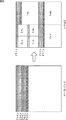
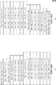
この伝送順の例を図24および図25に示す。図24および図25において、各係数ラインは、その伝送順に並べられている。図中上から下に向かう向きに時系列が示されている。つまり、図24および図25に示される各係数ラインは、図中上から順に伝送される。 Examples of this transmission order are shown in FIGS. 24 and 25, the coefficient lines are arranged in the order of transmission. A time series is shown from the top to the bottom in the figure. That is, the coefficient lines shown in FIGS. 24 and 25 are transmitted in order from the top in the figure.
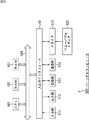
図24Aは、各分割レベルの係数ラインを低域成分から高域成分に向かう順に伝送する例を示している。図24Bは、各分割レベルの係数ラインを高域成分から低域成分に向かう順に伝送する例を示している。図25Aは、各分割レベルの係数ラインをウェーブレット変換処理された順のまま伝送する例を示している。図25Bは、各分割レベルの係数ラインをウェーブレット逆変換処理された順に伝送する例を示している。 FIG. 24A shows an example in which coefficient lines at each division level are transmitted in order from the low frequency component to the high frequency component. FIG. 24B illustrates an example in which coefficient lines at each division level are transmitted in order from the high frequency component to the low frequency component. FIG. 25A shows an example in which coefficient lines at each division level are transmitted in the order of wavelet transform processing. FIG. 25B shows an example in which the coefficient lines at each division level are transmitted in the order in which the wavelet inverse transform processing is performed.
図24A、図24B、および図25Aの場合、伝送順が、ウェーブレット逆変換処理の順と異なるので、係数ライン並び替え部302は、この伝送順を把握し、それをウェーブレット逆変換処理の順に並び替える。
In the case of FIGS. 24A, 24B, and 25A, since the transmission order is different from the order of the wavelet inverse transformation process, the coefficient
図25Bの場合、係数ライン並び替え部302は、並び替えを省略し、そのままの順で係数データを逆量子化部204に供給する。つまり、係数ライン読み出し部312は、各分割レベルの係数ラインを、係数ライン並び替えバッファ311に保持された順に読み出し、逆量子化部204に供給する。
In the case of FIG. 25B, the coefficient
なお、上述したように、選択部211の選択により符号ラインの並びは変化しない。したがって、上述したどの場合であっても、係数ライン並び替えバッファ311は、サブバンド・ライン選択部202により選択された分割レベルの係数ラインによらず(生成する復号画像の解像度によらず)、同様の方法で係数データの並び替えを行うことができる。
As described above, the arrangement of the code lines is not changed by the selection of the
[処理の流れ]
以上のような画像復号装置300の各部により実行される復号処理の流れの例を、図26のフローチャートを参照して説明する。なお、この復号処理は、1ピクチャ分の画像に対応する符号化データ毎に実行される。
[Process flow]
An example of the flow of decoding processing executed by each unit of the image decoding device 300 as described above will be described with reference to the flowchart of FIG. This decoding process is executed for each encoded data corresponding to an image for one picture.
この画像復号装置300の場合も、画像復号処理は、基本的に、図21のフローチャートを参照して説明した画像復号装置200の場合と同様に実行される。 In the case of this image decoding apparatus 300 as well, the image decoding process is basically executed in the same manner as in the case of the image decoding apparatus 200 described with reference to the flowchart of FIG.
すなわち、画像復号装置300の各部は、ステップS301乃至ステップS307の各処理を、図21のステップS201乃至ステップS207の各処理と同様に実行する。 That is, each unit of the image decoding device 300 executes the processes in steps S301 to S307 in the same manner as the processes in steps S201 to S207 in FIG.
ステップS308において、係数ライン並び替え部302は、係数データをウェーブレット逆変換の順に並び替える。
In step S308, the coefficient
画像復号装置300の各部は、ステップS309乃至ステップS311の各処理を、図21のステップS208乃至ステップS210の各処理と同様に実行する。 Each unit of the image decoding device 300 executes the processes in steps S309 to S311 in the same manner as the processes in steps S208 to S210 in FIG.
以上のように、復号処理を実行することにより、画像復号装置300は、画像が符号化された符号化データを低遅延かつスケーラブルに復号することができる。 As described above, by executing the decoding process, the image decoding device 300 can decode the encoded data obtained by encoding the image with low delay and in a scalable manner.
なお、画像復号装置300において、係数ライン並び替え部302の位置は、ウェーブレット逆変換部205より前の位置であればよい。例えば、サブバンド・ライン選択部202とエントロピ復号部203との間に係数ライン並び替え部302を設けるようにしてもよいし、逆量子化部204とウェーブレット逆変換部205との間に係数ライン並び替え部302を設けるようにしてもよい。
In the image decoding apparatus 300, the position of the coefficient
<3.第3の実施の形態>
[システムの構成]
第1の実施の形態で説明した画像符号化装置100と、画像復号装置200(若しくは、第2の実施の形態で説明した画像復号装置300)との適用例について説明する。図27は、入力画像を符号化して伝送し、その符号化データを伝送先で復号し、得られた復号画像を出力する画像伝送システムの構成例を示す図である。
<3. Third Embodiment>
[System configuration]
An application example of the image coding apparatus 100 described in the first embodiment and the image decoding apparatus 200 (or the image decoding apparatus 300 described in the second embodiment) will be described. FIG. 27 is a diagram illustrating a configuration example of an image transmission system that encodes and transmits an input image, decodes the encoded data at a transmission destination, and outputs the obtained decoded image.
画像伝送システム400は、画像をより低遅延に伝送するシステムである。画像伝送システム400は、ネットワーク402を介して接続される送信装置401および受信装置403を有する。 The image transmission system 400 is a system that transmits an image with lower delay. The image transmission system 400 includes a transmission device 401 and a reception device 403 that are connected via a network 402.
送信装置401は、入力画像を、ネットワーク402を介して受信装置403に送信する装置である。送信装置401は、効率よく画像を伝送するために、画像データを符号化し、その符号化データを受信装置403に送信する。 The transmission device 401 is a device that transmits an input image to the reception device 403 via the network 402. The transmission device 401 encodes image data and transmits the encoded data to the reception device 403 in order to efficiently transmit an image.
送信装置401は、符号化部411、パケタイズ処理部412、および送信部413を有する。
The transmission apparatus 401 includes an
符号化部411は、入力画像を符号化し、符号化データを出力する。符号化部411には、第1の実施の形態において説明した画像符号化装置100が適用される。つまり、符号化部411は、画像符号化装置100と同様の構成を有し、同様の処理を行う。
The
パケタイズ処理部412は、符号化部411から出力される符号化データ(コードストリーム)をパケット化する。送信部413は、パケタイズ処理部412により生成されたパケットを、ネットワーク402を介して受信部421に送信する。
The
ネットワーク402は、例えばインターネットや無線LAN等に代表される任意の通信網であり、送信装置401から受信装置403に伝送される符号化データの伝送路である。ネットワーク402の構成は任意であり、複数のネットワークの集合により構成されてもよいし、その一部または全部が、有線または無線のいずれにより構成されるようにしてもよい。 The network 402 is an arbitrary communication network represented by, for example, the Internet or a wireless LAN, and is a transmission path for encoded data transmitted from the transmission device 401 to the reception device 403. The configuration of the network 402 is arbitrary, and may be configured by a set of a plurality of networks, or a part or all of the network 402 may be configured by either wired or wireless.
受信装置403は、ネットワーク402を介して送信装置401から供給されるパケットを受信し、そのパケットに含まれる符号化データを復号し、復号画像を生成し、出力する装置である。 The receiving device 403 is a device that receives a packet supplied from the transmitting device 401 via the network 402, decodes encoded data included in the packet, generates a decoded image, and outputs the decoded image.
受信装置403は、受信部421、デパケタイズ処理部422、および復号部423を有する。
The reception device 403 includes a
受信部421は、送信装置401の送信部413に対応する処理を行い、送信部413からネットワークを介して供給されるパケットを受信する処理を行う。
The
デパケタイズ処理部422は、受信部421において受信されたパケットをデパケタイズし、符号化データを抽出する。
The
復号部423は、デパケタイズ処理部422により抽出された符号化データを復号し、復号画像を出力する。復号部423には、第1の実施の形態において説明した画像復号装置200(若しくは、第2の実施の形態において説明した画像復号装置300)が適用される。つまり、復号部423は、画像復号装置200(若しくは画像復号装置300)と同様の構成を有し、同様の処理を行う。
The
このように、復号部423として画像復号装置200を適用することにより、受信装置403は、符号化データを低遅延かつスケーラブルに復号することができる。また、係数ライン並び替え部302を有する画像復号装置300を復号部423として適用することにより、受信装置403は、より多様な画像符号化装置に対して、符号化データを低遅延かつスケーラブルに復号することができる。
Thus, by applying the image decoding device 200 as the
<4.第4の実施の形態>
[パーソナルコンピュータ]
上述した一連の処理は、ハードウェアにより実行させることもできるし、ソフトウェアにより実行させることもできる。この場合、例えば、図28に示されるようなパーソナルコンピュータとして構成されるようにしてもよい。
<4. Fourth Embodiment>
[Personal computer]
The series of processes described above can be executed by hardware or can be executed by software. In this case, for example, a personal computer as shown in FIG. 28 may be configured.
図28において、パーソナルコンピュータ500のCPU501は、ROM(Read Only Memory)502に記憶されているプログラム、または記憶部513からRAM(Random Access Memory)503にロードされたプログラムに従って各種の処理を実行する。RAM503にはまた、CPU501が各種の処理を実行する上において必要なデータなども適宜記憶される。
In FIG. 28, the
CPU501、ROM502、およびRAM503は、バス504を介して相互に接続されている。このバス504にはまた、入出力インタフェース510も接続されている。
The
入出力インタフェース510には、キーボード、マウスなどよりなる入力部511、CRT(Cathode Ray Tube)やLCD(Liquid Crystal Display)などよりなるディスプレイ、並びにスピーカなどよりなる出力部512、ハードディスクなどより構成される記憶部513、モデムなどより構成される通信部514が接続されている。通信部514は、インターネットを含むネットワークを介しての通信処理を行う。
The input /
入出力インタフェース510にはまた、必要に応じてドライブ515が接続され、磁気ディスク、光ディスク、光磁気ディスク、或いは半導体メモリなどのリムーバブルメディア521が適宜装着され、それらから読み出されたコンピュータプログラムが、必要に応じて記憶部513にインストールされる。
A
上述した一連の処理をソフトウェアにより実行させる場合には、そのソフトウェアを構成するプログラムが、ネットワークや記録媒体からインストールされる。 When the above-described series of processing is executed by software, a program constituting the software is installed from a network or a recording medium.
この記録媒体は、例えば、図28に示されるように、装置本体とは別に、ユーザにプログラムを配信するために配布される、プログラムが記録されている磁気ディスク(フレキシブルディスクを含む)、光ディスク(CD-ROM(Compact Disc - Read Only Memory),DVD(Digital Versatile Disc)を含む)、光磁気ディスク(MD(Mini Disc)を含む)、もしくは半導体メモリなどよりなるリムーバブルメディア521により構成されるだけでなく、装置本体に予め組み込まれた状態でユーザに配信される、プログラムが記録されているROM502や、記憶部513に含まれるハードディスクなどで構成される。
For example, as shown in FIG. 28, this recording medium is distributed to distribute a program to a user separately from the apparatus main body, and includes a magnetic disk (including a flexible disk) on which a program is recorded, an optical disk ( It only consists of
なお、コンピュータが実行するプログラムは、本明細書で説明する順序に沿って時系列に処理が行われるプログラムであっても良いし、並列に、あるいは呼び出しが行われたとき等の必要なタイミングで処理が行われるプログラムであっても良い。 The program executed by the computer may be a program that is processed in time series in the order described in this specification, or in parallel or at a necessary timing such as when a call is made. It may be a program for processing.
また、本明細書において、記録媒体に記録されるプログラムを記述するステップは、記載された順序に沿って時系列的に行われる処理はもちろん、必ずしも時系列的に処理されなくとも、並列的あるいは個別に実行される処理をも含むものである。 Further, in the present specification, the step of describing the program recorded on the recording medium is not limited to the processing performed in chronological order according to the described order, but may be performed in parallel or It also includes processes that are executed individually.
また、本明細書において、システムとは、複数のデバイス(装置)により構成される装置全体を表すものである。 Further, in this specification, the system represents the entire apparatus composed of a plurality of devices (apparatuses).
また、以上において、1つの装置(または処理部)として説明した構成を分割し、複数の装置(または処理部)として構成するようにしてもよい。逆に、以上において複数の装置(または処理部)として説明した構成をまとめて1つの装置(または処理部)として構成されるようにしてもよい。また、各装置(または各処理部)の構成に上述した以外の構成を付加するようにしてももちろんよい。さらに、システム全体としての構成や動作が実質的に同じであれば、ある装置(または処理部)の構成の一部を他の装置(または他の処理部)の構成に含めるようにしてもよい。つまり、本発明の実施の形態は、上述した実施の形態に限定されるものではなく、本発明の要旨を逸脱しない範囲において種々の変更が可能である。 In addition, in the above description, the configuration described as one device (or processing unit) may be divided and configured as a plurality of devices (or processing units). Conversely, the configurations described above as a plurality of devices (or processing units) may be combined into a single device (or processing unit). Of course, a configuration other than that described above may be added to the configuration of each device (or each processing unit). Furthermore, if the configuration and operation of the entire system are substantially the same, a part of the configuration of a certain device (or processing unit) may be included in the configuration of another device (or other processing unit). . That is, the embodiment of the present invention is not limited to the above-described embodiment, and various modifications can be made without departing from the gist of the present invention.
100 画像符号化装置, 101 画像ライン入力部, 102 ラインバッファ部, 103 ウェーブレット変換部, 104 係数ライン並び替え部, 105 量子化部, 106 エントロピ符号化部, 107 付加部, 108 レート制御部, 111 係数ライン並び替えバッファ, 112 係数ライン読み出し部, 200 画像復号装置, 201 符号語解読部, 202 サブバンド・ライン選択部, 203 エントロピ復号部, 204 逆量子化部, 205 ウェーブレット逆変換部, 206 バッファ部, 211 選択部, 212 保持部, 300 画像復号装置, 301 符号語解読部, 302 係数ライン並び替え部, 311 係数ライン並び替えバッファ, 312 係数ライン読み出し部 DESCRIPTION OF SYMBOLS 100 Image coding apparatus, 101 Image line input part, 102 Line buffer part, 103 Wavelet transformation part, 104 Coefficient line rearrangement part, 105 Quantization part, 106 Entropy encoding part, 107 Addition part, 108 Rate control part, 111 Coefficient line rearrangement buffer, 112 coefficient line reading unit, 200 image decoding device, 201 codeword decoding unit, 202 subband line selection unit, 203 entropy decoding unit, 204 inverse quantization unit, 205 wavelet inverse transformation unit, 206 buffer , 211 selection unit, 212 holding unit, 300 image decoding device, 301 codeword decoding unit, 302 coefficient line rearranging unit, 311 coefficient line rearranging buffer, 312 coefficient line reading unit
Claims (10)
前記選択手段により選択された符号化データを、復号する復号手段と、
階層的に前記合成フィルタ処理を行い、前記復号手段により復号されて得られた前記係数データを合成し、前記所定の解像度の復号画像を生成する合成フィルタ手段と
を備える画像処理装置。 A line block composed of coefficient data groups of each subband, including at least one line of coefficient data of subbands of at least the lowest frequency component, in which image data of a predetermined number of lines is decomposed for each frequency band by hierarchical analysis filter processing Selecting means for selecting encoded data corresponding to coefficient data of a subband necessary for generating a decoded image of a predetermined resolution from encoded data generated by encoding;
Decoding means for decoding the encoded data selected by the selection means;
An image processing apparatus comprising: synthesis filter means that hierarchically performs the synthesis filter processing, synthesizes the coefficient data obtained by decoding by the decoding means, and generates a decoded image of the predetermined resolution.
前記選択手段は、前記解読手段による解読結果に基づいて、前記符号化データを、各階層の前記係数データの1ライン分に対応する符号化データ毎に分割し、その中から、所定の解像度の復号画像を生成するのに必要なサブバンドの係数データに対応する符号化データを選択する
請求項1に記載の画像処理装置。 Further comprising decoding means for decoding the encoded data,
The selection unit divides the encoded data into encoded data corresponding to one line of the coefficient data of each layer based on a decoding result by the decoding unit, and from among the encoded data, a predetermined resolution is obtained. The image processing device according to claim 1, wherein encoded data corresponding to subband coefficient data necessary for generating a decoded image is selected.
前記選択手段は、前記符号量に基づいて、前記符号化データを、各階層の前記係数データの1ライン分に対応する符号化データ毎に分割し、その中から、所定の解像度の復号画像を生成するのに必要なサブバンドの係数データに対応する符号化データを選択する
請求項2に記載の画像処理装置。 The decoding means extracts the information on the code amount of the encoded data corresponding to one line of the coefficient data of each layer included in the encoded data by decoding the encoded data,
The selection unit divides the encoded data into encoded data corresponding to one line of the coefficient data in each layer based on the code amount, and from among the encoded data, a decoded image having a predetermined resolution is divided. The image processing device according to claim 2, wherein encoded data corresponding to coefficient data of a subband necessary for generation is selected.
前記選択手段は、前記マーカの検出結果に基づいて、前記符号化データを、各階層の前記係数データの1ライン分に対応する符号化データ毎に分割し、その中から、所定の解像度の復号画像を生成するのに必要なサブバンドの係数データに対応する符号化データを選択する
請求項2に記載の画像処理装置。 The decoding means detects a marker indicating a boundary of encoded data corresponding to one line of the coefficient data of each layer included in the encoded data by decoding the encoded data,
The selection unit divides the encoded data into encoded data corresponding to one line of the coefficient data in each layer based on the detection result of the marker, and decodes a predetermined resolution from the divided data The image processing apparatus according to claim 2, wherein encoded data corresponding to coefficient data of a subband necessary for generating an image is selected.
前記合成フィルタ手段は、前記係数データ並び替え手段により並び替えられた各サブバンドの前記係数データを合成し、前記所定の解像度の復号画像を生成する
請求項1に記載の画像処理装置。 Coefficient data rearranging means for rearranging the arrangement order of the coefficient data obtained by decoding by the decoding means from the order decoded by the decoding means in the order of the synthesis filter processing,
The image processing apparatus according to claim 1, wherein the synthesis filter unit synthesizes the coefficient data of each subband rearranged by the coefficient data rearrangement unit to generate a decoded image having the predetermined resolution.
請求項1に記載の画像処理装置。 The image processing apparatus according to claim 1, wherein the synthesis filter unit preferentially executes the synthesis filter process on subband coefficient data of a lower hierarchy among executable.
請求項1に記載の画像処理装置。 The image processing apparatus according to claim 1, wherein the synthesis filter unit performs the synthesis filter process using a lifting operation.
請求項7に記載の画像処理装置。 The synthesizing filter means performs the lifting calculation after symmetrically extending necessary coefficient data for the initial state line block, and the previous lifting calculation result for the steady state line block. The image processing apparatus according to claim 7, wherein the lifting operation is performed using the image processing apparatus.
請求項7に記載の画像処理装置。 The image processing apparatus according to claim 7, wherein the synthesis filter unit performs the lifting operation on the coefficient data in a horizontal direction and then performs the lifting operation in a vertical direction.
前記画像処理装置の復号手段が、選択された符号化データを復号し、
前記画像処理装置の合成フィルタ手段が、階層的に前記合成フィルタ処理を行い、復号されて得られた前記係数データを合成し、前記所定の解像度の復号画像を生成する
画像処理方法。 The selection means of the image processing apparatus includes at least one line of coefficient data of at least the lowest frequency component subband obtained by decomposing image data of a predetermined number of lines for each frequency band by hierarchical analysis filter processing. From the encoded data generated by encoding the line block consisting of the coefficient data group, select encoded data corresponding to the coefficient data of the subband necessary to generate a decoded image of a predetermined resolution,
Decoding means of the image processing device decodes the selected encoded data;
An image processing method in which a synthesis filter unit of the image processing device performs the synthesis filter processing hierarchically, synthesizes the coefficient data obtained by decoding, and generates a decoded image of the predetermined resolution.
Priority Applications (4)
| Application Number | Priority Date | Filing Date | Title |
|---|---|---|---|
| JP2009219628A JP2011071649A (en) | 2009-09-24 | 2009-09-24 | Image processing apparatus and method |
| US12/879,711 US20110069897A1 (en) | 2009-09-24 | 2010-09-10 | Image processing device and method |
| CN2010102879941A CN102036064A (en) | 2009-09-24 | 2010-09-16 | Image processing device and method |
| EP20100177300 EP2312855A3 (en) | 2009-09-24 | 2010-09-17 | Low delay scalable image coding |
Applications Claiming Priority (1)
| Application Number | Priority Date | Filing Date | Title |
|---|---|---|---|
| JP2009219628A JP2011071649A (en) | 2009-09-24 | 2009-09-24 | Image processing apparatus and method |
Publications (2)
| Publication Number | Publication Date |
|---|---|
| JP2011071649A true JP2011071649A (en) | 2011-04-07 |
| JP2011071649A5 JP2011071649A5 (en) | 2012-10-25 |
Family
ID=43301916
Family Applications (1)
| Application Number | Title | Priority Date | Filing Date |
|---|---|---|---|
| JP2009219628A Abandoned JP2011071649A (en) | 2009-09-24 | 2009-09-24 | Image processing apparatus and method |
Country Status (4)
| Country | Link |
|---|---|
| US (1) | US20110069897A1 (en) |
| EP (1) | EP2312855A3 (en) |
| JP (1) | JP2011071649A (en) |
| CN (1) | CN102036064A (en) |
Cited By (1)
| Publication number | Priority date | Publication date | Assignee | Title |
|---|---|---|---|---|
| JP2020502960A (en) * | 2016-12-19 | 2020-01-23 | フラウンホファー ゲセルシャフト ツール フェールデルンク ダー アンゲヴァンテン フォルシュンク エー.ファオ. | Apparatus and method for encoding or decoding using subband dependent prediction adaptation for GCLI entropy encoding |
Families Citing this family (3)
| Publication number | Priority date | Publication date | Assignee | Title |
|---|---|---|---|---|
| US8958510B1 (en) * | 2010-06-10 | 2015-02-17 | Fredric J. Harris | Selectable bandwidth filter |
| CN105491392B (en) * | 2015-11-24 | 2019-03-29 | 北京优素科技有限公司 | Multistage IDWT method for parallel processing and system |
| CN115546236B (en) * | 2022-11-24 | 2023-04-07 | 阿里巴巴(中国)有限公司 | Image segmentation method and device based on wavelet transformation |
Family Cites Families (8)
| Publication number | Priority date | Publication date | Assignee | Title |
|---|---|---|---|---|
| US339658A (en) * | 1886-04-13 | Luthee c | ||
| US6339658B1 (en) * | 1999-03-09 | 2002-01-15 | Rockwell Science Center, Llc | Error resilient still image packetization method and packet structure |
| AUPQ156299A0 (en) * | 1999-07-12 | 1999-08-05 | Canon Kabushiki Kaisha | Method and apparatus for discrete wavelet transforms and compressed bitstream ordering for block entropy coding of subband image data |
| JP2005341316A (en) * | 2004-05-27 | 2005-12-08 | Sony Corp | Information processing system and method, information processing apparatus and method, and its program |
| JP4371120B2 (en) | 2006-05-16 | 2009-11-25 | ソニー株式会社 | Image processing apparatus, image processing method, program, and recording medium |
| JPWO2008093698A1 (en) * | 2007-01-31 | 2010-05-20 | ソニー株式会社 | Information processing apparatus and method |
| US8503809B2 (en) * | 2007-05-17 | 2013-08-06 | Sony Corporation | Information processing apparatus and method to entropy code upon processing of predetermined number of precincts |
| US20100016053A1 (en) * | 2008-04-17 | 2010-01-21 | Walker Jay S | Products and processes for applying conditions to a lottery entry |
-
2009
- 2009-09-24 JP JP2009219628A patent/JP2011071649A/en not_active Abandoned
-
2010
- 2010-09-10 US US12/879,711 patent/US20110069897A1/en not_active Abandoned
- 2010-09-16 CN CN2010102879941A patent/CN102036064A/en active Pending
- 2010-09-17 EP EP20100177300 patent/EP2312855A3/en not_active Withdrawn
Cited By (2)
| Publication number | Priority date | Publication date | Assignee | Title |
|---|---|---|---|---|
| JP2020502960A (en) * | 2016-12-19 | 2020-01-23 | フラウンホファー ゲセルシャフト ツール フェールデルンク ダー アンゲヴァンテン フォルシュンク エー.ファオ. | Apparatus and method for encoding or decoding using subband dependent prediction adaptation for GCLI entropy encoding |
| US10944972B2 (en) | 2016-12-19 | 2021-03-09 | Fraunhofer-Gesellschaft Zur Foerderung Der Angewandten Forschung E.V. | Apparatus and method for encoding or decoding using a subband dependent prediction adaptation for GCLI entropy coding |
Also Published As
| Publication number | Publication date |
|---|---|
| EP2312855A3 (en) | 2011-04-27 |
| CN102036064A (en) | 2011-04-27 |
| EP2312855A2 (en) | 2011-04-20 |
| US20110069897A1 (en) | 2011-03-24 |
Similar Documents
| Publication | Publication Date | Title |
|---|---|---|
| JP4656190B2 (en) | Information processing apparatus and method | |
| TWI379593B (en) | Image processing apparatus and image processing method | |
| JP5263621B2 (en) | Image processing apparatus and method | |
| CN101309417B (en) | Apparatus and method for processing image data | |
| JP2012060261A (en) | Image processing apparatus and method | |
| JP4124792B2 (en) | Encoding method, decoding method, encoding device, and decoding device | |
| US8391616B2 (en) | Information processor and method therefor | |
| JP2005295561A (en) | Method for encoding and decoding dynamic-image data, device for displaying image sequence encoded by using its method and carrying out its method, computer program and storage medium | |
| JP2008288832A (en) | Information processing apparatus and method | |
| JP5469127B2 (en) | Image data encoding apparatus, operation control method thereof, and program thereof | |
| JP2007142614A (en) | Image processing apparatus and method, program, and information recording medium | |
| JP2010141659A (en) | Information processing device and method | |
| JP6566865B2 (en) | Moving picture decoding apparatus, moving picture decoding method, moving picture encoding apparatus, moving picture encoding method, and computer-readable recording medium | |
| JP2011071649A (en) | Image processing apparatus and method | |
| JP2013243477A (en) | Image processing apparatus and method, and program | |
| JP4086196B2 (en) | Image encoding apparatus, program, and storage medium | |
| JP2004166254A (en) | Image encoder and method, program and recording medium | |
| JP2011147050A (en) | Image processing apparatus and method | |
| JP2011160075A (en) | Image processing device and method | |
| JP5158000B2 (en) | Information processing apparatus and method | |
| JP2005092007A (en) | Image processing system, image processing method, program and information recording medium | |
| JP4670947B2 (en) | Information processing apparatus and method | |
| JP2013187692A (en) | Image processing device and image processing method | |
| JP2011239066A (en) | Device and method of processing image | |
| JP2004040388A (en) | Image processing apparatus |
Legal Events
| Date | Code | Title | Description |
|---|---|---|---|
| A521 | Written amendment |
Free format text: JAPANESE INTERMEDIATE CODE: A523 Effective date: 20120904 |
|
| A621 | Written request for application examination |
Free format text: JAPANESE INTERMEDIATE CODE: A621 Effective date: 20120904 |
|
| A762 | Written abandonment of application |
Free format text: JAPANESE INTERMEDIATE CODE: A762 Effective date: 20130415 |