JP2013106957A - Beam forming device and method, medical image system performing the same, and computer-readable recoding medium - Google Patents
Beam forming device and method, medical image system performing the same, and computer-readable recoding medium Download PDFInfo
- Publication number
- JP2013106957A JP2013106957A JP2012253498A JP2012253498A JP2013106957A JP 2013106957 A JP2013106957 A JP 2013106957A JP 2012253498 A JP2012253498 A JP 2012253498A JP 2012253498 A JP2012253498 A JP 2012253498A JP 2013106957 A JP2013106957 A JP 2013106957A
- Authority
- JP
- Japan
- Prior art keywords
- echo signal
- basis vectors
- weight value
- beam forming
- subject
- Prior art date
- Legal status (The legal status is an assumption and is not a legal conclusion. Google has not performed a legal analysis and makes no representation as to the accuracy of the status listed.)
- Pending
Links
Images


Classifications
-
- A—HUMAN NECESSITIES
- A61—MEDICAL OR VETERINARY SCIENCE; HYGIENE
- A61B—DIAGNOSIS; SURGERY; IDENTIFICATION
- A61B8/00—Diagnosis using ultrasonic, sonic or infrasonic waves
- A61B8/13—Tomography
- A61B8/14—Echo-tomography
-
- G—PHYSICS
- G01—MEASURING; TESTING
- G01S—RADIO DIRECTION-FINDING; RADIO NAVIGATION; DETERMINING DISTANCE OR VELOCITY BY USE OF RADIO WAVES; LOCATING OR PRESENCE-DETECTING BY USE OF THE REFLECTION OR RERADIATION OF RADIO WAVES; ANALOGOUS ARRANGEMENTS USING OTHER WAVES
- G01S7/00—Details of systems according to groups G01S13/00, G01S15/00, G01S17/00
- G01S7/52—Details of systems according to groups G01S13/00, G01S15/00, G01S17/00 of systems according to group G01S15/00
- G01S7/52017—Details of systems according to groups G01S13/00, G01S15/00, G01S17/00 of systems according to group G01S15/00 particularly adapted to short-range imaging
- G01S7/52046—Techniques for image enhancement involving transmitter or receiver
- G01S7/52047—Techniques for image enhancement involving transmitter or receiver for elimination of side lobes or of grating lobes; for increasing resolving power
-
- A—HUMAN NECESSITIES
- A61—MEDICAL OR VETERINARY SCIENCE; HYGIENE
- A61B—DIAGNOSIS; SURGERY; IDENTIFICATION
- A61B8/00—Diagnosis using ultrasonic, sonic or infrasonic waves
- A61B8/52—Devices using data or image processing specially adapted for diagnosis using ultrasonic, sonic or infrasonic waves
- A61B8/5207—Devices using data or image processing specially adapted for diagnosis using ultrasonic, sonic or infrasonic waves involving processing of raw data to produce diagnostic data, e.g. for generating an image
-
- G—PHYSICS
- G01—MEASURING; TESTING
- G01S—RADIO DIRECTION-FINDING; RADIO NAVIGATION; DETERMINING DISTANCE OR VELOCITY BY USE OF RADIO WAVES; LOCATING OR PRESENCE-DETECTING BY USE OF THE REFLECTION OR RERADIATION OF RADIO WAVES; ANALOGOUS ARRANGEMENTS USING OTHER WAVES
- G01S15/00—Systems using the reflection or reradiation of acoustic waves, e.g. sonar systems
- G01S15/88—Sonar systems specially adapted for specific applications
- G01S15/89—Sonar systems specially adapted for specific applications for mapping or imaging
- G01S15/8906—Short-range imaging systems; Acoustic microscope systems using pulse-echo techniques
- G01S15/8977—Short-range imaging systems; Acoustic microscope systems using pulse-echo techniques using special techniques for image reconstruction, e.g. FFT, geometrical transformations, spatial deconvolution, time deconvolution
-
- G—PHYSICS
- G06—COMPUTING; CALCULATING OR COUNTING
- G06T—IMAGE DATA PROCESSING OR GENERATION, IN GENERAL
- G06T1/00—General purpose image data processing
Abstract
Description
本発明は、ビームフォーミング方法に係り、より詳しくは、これを行う装置、医療画像システム、並びにコンピュータで読取可能な記録媒体に関する。 The present invention relates to a beamforming method, and more particularly to an apparatus for performing the method, a medical imaging system, and a computer-readable recording medium.
画像システムにおいて、固定型ビームフォーミング(Fixed Beamforming)技法又は適応型ビームフォーミング(Adaptive Beamforming)技法が利用できる。固定型ビームフォーミング技法は、入力信号と関係なく、ハミングウィンドウ(Hamming window)又はハニングウィンドウ(Hanning window)を利用する方法であって、データ独立型ビームフォーミング(Data−Independent Beamforming)とも言う。適応型ビームフォーミング技法は、入力信号によるビームフォーミング係数を利用する方法であって、データ依存型ビームフォーミング(Data−Dependent Beamforming)とも言う。 In the imaging system, a fixed beamforming technique or an adaptive beamforming technique can be used. The fixed beamforming technique uses a hamming window or a hanning window regardless of an input signal, and is also referred to as data-independent beamforming. The adaptive beamforming technique uses a beamforming coefficient based on an input signal, and is also called data-dependent beamforming (Data-Dependent Beamforming).
本発明が解決しようとする課題は、より高解像度の診断画像を、より少ない演算量で生成できるビームフォーミング装置及び方法、並びにこれを行う医療画像システムを提供することである。また、前記方法をコンピュータで実行させるためのプログラムを記録したコンピュータで読取可能な記録媒体を提供することである。また、本発明が解決しようとする課題は、前記のような技術的課題に限定されず、さらに他の技術的課題が、本発明の詳細な説明から明らかになるか、又は、本発明の実施形態を実行することで習得できるであろう。 The problem to be solved by the present invention is to provide a beam forming apparatus and method capable of generating a higher-resolution diagnostic image with a smaller amount of calculation, and a medical image system for performing the same. Another object of the present invention is to provide a computer-readable recording medium that records a program for causing the computer to execute the method. The problems to be solved by the present invention are not limited to the technical problems as described above, and other technical problems will become clear from the detailed description of the present invention, or the implementation of the present invention. It can be learned by executing the form.
前記課題を解決するためのビームフォーミング装置は、既測定のエコー信号のビームフォーミング係数から獲得された複数の基底ベクトル(Basis vector)を保存する保存部と、前記保存された複数の基底ベクトルを利用して、被写体から反射されたエコー信号に適用される加重値を算出する加重値算出部と、前記保存された複数の基底ベクトルを利用して、前記被写体から反射されたエコー信号に前記算出された加重値を適用し、前記加重値が適用された信号を合成する合成部と、を備える。 A beamforming apparatus for solving the above-described problems uses a storage unit that stores a plurality of basis vectors acquired from beamforming coefficients of a measured echo signal, and uses the plurality of stored basis vectors. Then, the weight value calculation unit that calculates a weight value applied to the echo signal reflected from the subject and the plurality of stored base vectors are used to calculate the echo signal reflected from the subject. And a combining unit that applies the weighted value and combines the signal to which the weighted value is applied.
前記他の課題を解決するための医療画像システムは、既測定のエコー信号のビームフォーミング係数から獲得された複数の基底ベクトルを利用して、被写体から反射されたエコー信号に適用される加重値を算出し、前記被写体から反射されたエコー信号に前記算出された加重値を適用し、前記加重値が適用された信号を合成するビームフォーミング装置と、前記ビームフォーミング装置から出力された信号を利用して診断画像を生成する診断画像生成部と、を備える。 A medical imaging system for solving the other problems uses a plurality of basis vectors obtained from beamforming coefficients of a measured echo signal, and calculates a weight value applied to the echo signal reflected from the subject. Calculating, applying the calculated weighted value to the echo signal reflected from the subject, and combining the signal to which the weighted value is applied, and a signal output from the beamforming apparatus. And a diagnostic image generation unit that generates a diagnostic image.
前記さらに他の課題を解決するためのビームフォーミング方法は、既測定のエコー信号のビームフォーミング係数から獲得された複数の基底ベクトルを利用して、被写体から反射されたエコー信号に適用される加重値を算出するステップと、前記複数の基底ベクトルを利用して、前記被写体から反射されたエコー信号に前記算出された加重値を適用し、前記加重値が適用された信号を合成するステップと、を含む。 A beamforming method for solving the further another problem is a weighting value applied to an echo signal reflected from an object using a plurality of basis vectors obtained from a beamforming coefficient of an already measured echo signal. And applying the calculated weight to the echo signal reflected from the subject using the plurality of basis vectors, and synthesizing the signal to which the weight is applied. Including.
前記さらに他の課題を解決するための前記ビームフォーミング方法をコンピュータで実行させるためのプログラムを記録したコンピュータで読取可能な記録媒体を提供する。 A computer-readable recording medium on which a program for causing a computer to execute the beam forming method for solving the further another problem is recorded.
本発明によればエコー信号の次元を低減できるので、リアルタイム高解像度診断画像を獲得するためのビームフォーミングにおいて、処理せねばならない演算量が顕著に減少する。 According to the present invention, since the dimension of the echo signal can be reduced, the amount of calculation that must be processed in beam forming for obtaining a real-time high-resolution diagnostic image is significantly reduced.
以下、図面を参照して本発明の実施形態をさらに詳細に説明する。
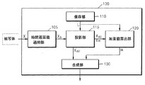
図1は、本実施形態によるビームフォーミング装置100の一例を示した図面である。図1を参照すれば、ビームフォーミング装置100は、保存部110、加重値算出部120及び合成部130で構成される。
Hereinafter, embodiments of the present invention will be described in more detail with reference to the drawings.
FIG. 1 is a diagram illustrating an example of a
図1に示したビームフォーミング装置100には、本実施形態に関連する構成要素だけが示されている。従って、当業者ならば、図1に示した構成要素以外に、他の汎用的な構成要素がさらに含まれ得ることが分かるであろう。
In the
また、図1に示したビームフォーミング装置100の加重値算出部120及び合成部130は、一つ又は複数のプロセッサに相当する。プロセッサは、複数の論理ゲートのアレイで具現されるか、又は汎用的なマイクロプロセッサと該マイクロプロセッサで実行されるプログラムが保存されたメモリとの組合わせて具現される。また、当業者ならば、他の形態のハードウェアでも具現できることが分かるであろう。
In addition, the
ビームフォーミング装置100は、被写体から反射されたエコー信号を利用して受信ビームを形成する装置である。この時、例えば、被写体は人体の腹部、心臓などであり、エコー信号は被写体から反射された超音波信号であるが、これに限定されない。
The
保存部110は、既測定のエコー信号のビームフォーミング係数から獲得された複数の基底ベクトルを保存する。この時、ビームフォーミング係数は、チャネル別又はサブアレイ(sub−array)別に適用される加重値(weight)となる。本実施形態によるチャネルは例えば、エコー信号を受信するトランスデューサ(transducer)であり、サブアレイは例えば、複数のトランスデューサを含む副開口(sub−aperture、サブアパーチャ)であるが、これに限定されない。
The
本実施形態における既測定のエコー信号は例えば、所定の被写体から反射されたエコー信号であり、この時、所定の被写体は、ビームフォーミング装置100でビームフォーミングを行うエコー信号に対する被写体と同一であるが、これに限定されない。
The already measured echo signal in the present embodiment is, for example, an echo signal reflected from a predetermined subject. At this time, the predetermined subject is the same as the subject for the echo signal subjected to beam forming by the
例えば、保存部110は、既測定のエコー信号のビームフォーミング係数に主成分分析(Principal Component Analysis:PCA)を行って獲得された複数の基底ベクトルを保存する。
For example, the
さらに詳細に説明すれば、既測定のエコー信号のビームフォーミング係数は、最小分散法(Minimum variance technique)によって、チャネル別又はサブアレイ別に算出される。この時、最小分散法によって算出されたビームフォーミング係数は、最適加重値(optimal weight)となる。 More specifically, the beamforming coefficient of the already measured echo signal is calculated for each channel or each subarray by the minimum variance technique (Minimum Variance Technique). At this time, the beamforming coefficient calculated by the minimum dispersion method is an optimal weight.
最小分散法によって算出されたビームフォーミング係数を利用して主成分分析を行うことによって、複数のアイゲンベクトル(Eigen vector、固有ベクトル)が獲得され、獲得されたアイゲンベクトルのうち一部が基底ベクトルとして保存部110に保存される。
By performing principal component analysis using the beamforming coefficient calculated by the minimum variance method, multiple Eigen vectors (Eigen vectors) are acquired, and some of the acquired Eigen vectors are stored as basis vectors Stored in the
この時、保存部110に保存される基底ベクトルは、主成分分析によって獲得されたアイゲンベクトルのうち、アイゲンバリュー(Eigen value、固有値)が大きい順序による所定数のベクトルとなる。ユーザは、保存部110に保存される基底ベクトルの数を決定し、決定された数だけの基底ベクトルが保存部110に保存される。本実施形態によるビームフォーミング装置100のユーザは例えば、医者、看護婦、医療画像専門家などの医療専門家であるが、これに限定されず、ビームフォーミング装置100の設計者も含まれる。
At this time, the basis vectors stored in the
主成分分析によって獲得されるアイゲンベクトル及び基底ベクトルについて、以下、図2(A)及び図2(B)を参照してさらに詳細に説明する。
本実施形態による保存部110は、通常の記録媒体であって、例えば、ハードディスクドライブ(Hard Disk Drive:HDD)、ROM(Read Only Memory)、RAM(Random Access Memory)、フラッシュメモリ(Flash Memory)及びメモリカード(Memory Card)を含む記録媒体の何れかである。
Hereinafter, the Eigen vector and the basis vector acquired by the principal component analysis will be described in more detail with reference to FIG. 2 (A) and FIG. 2 (B).
The
加重値算出部120は、保存部110に保存された複数の基底ベクトルを利用して、被写体から反射されたエコー信号に適用される加重値を算出する。本実施形態による加重値算出部120によって算出される加重値は、アポダイゼーション(apodization)関数を構成する一つのパラメータとして使われる。また、被写体から反射されたエコー信号は、RF(Radio Frequency)データとなる。
The weight
本実施形態による加重値算出部120は例えば、保存部110に保存された複数の基底ベクトルを全て利用して加重値を算出するが、これに限定されず、ユーザの決定による所定数の基底ベクトルを利用して加重値を算出する方法もある。
For example, the
また、この時、加重値算出部120で加重値を算出するために利用されるエコー信号は、ビームフォーミングのための時間遅延値が適用されたエコー信号であるが、これに限定されない。本実施形態によるビームフォーミングのための時間遅延値は例えば、焦点(focal_point)とトランスデューサとの距離による誤差を補正する時間遅延値である。
At this time, the echo signal used to calculate the weight value by the weight
以下、被写体から反射されたエコー信号がM個のチャネルから受信される場合を例として説明するが、これに限定されず、被写体から反射されたエコー信号は、M個のサブアレイから受信される方法もある。 Hereinafter, a case where echo signals reflected from a subject are received from M channels will be described as an example. However, the present invention is not limited to this, and the echo signal reflected from a subject is received from M subarrays. There is also.
加重値算出部120は、保存部110に保存された基底ベクトルのうちM個未満の基底ベクトルを利用して、被写体から反射されたエコー信号に適用される加重値を算出する。
The
さらに詳細に説明すれば、加重値算出部120は、被写体から反射されたエコー信号を保存部110に保存された複数の基底ベクトルの各々に投影し、投影されたエコー信号を利用して加重値を算出する。これについては、以下、図3の加重値算出部120を参照してさらに詳細に説明する。
In more detail, the
このように、加重値算出部120で、基底ベクトルに投影されたエコー信号を利用して加重値を算出することによって、エコー信号の次元(dimension)が低減され、加重値を算出する演算量が著しく減少する。
As described above, the weight
合成部130は、保存部110に保存された複数の基底ベクトルを利用して、被写体から反射されたエコー信号に、加重値算出部120で算出された加重値を適用し、加重値が適用された信号を合成する。この時、合成部130は、ビームフォーミングのための時間遅延値が適用され、且つ、基底ベクトルに投影されたエコー信号に加重値を適用する。
The
本実施形態による合成部130は例えば、保存部110に保存された複数の基底ベクトルを全て利用して加重値を適用するが、これに限定されず、ユーザの決定による所定数の基底ベクトルを利用して加重値を適用する方法もある。
For example, the
これにより、合成部130は、被写体から反射されたエコー信号に、複数の基底ベクトルのうち少なくとも一部の基底ベクトルに係わる加重和を適用する。このような場合、基底ベクトルに対する加重和を適用するための加重値は、加重値算出部120で算出された加重値に対応する。
Thereby, the
また、合成部130は、加重値が適用された信号を合成する。合成部130は、加重値が適用された信号を合成した結果によって形成された受信ビームを出力する。
Further, the
例えば、合成部130は、加重値が適用された信号を合算して一つの受信ビームを形成する。合成部130は、加重値が適用された信号を合算することによって、焦点から反射された超音波信号を推定する。
For example, the synthesizing
これにより、本実施形態によるビームフォーミング装置100は、演算量を抑制しながら、高解像度診断画像を生成するための受信ビームを形成する。
Thereby, the
図2(A)及び図2(B)は、本実施形態によるアイゲンベクトル及び基底ベクトルの一例を示した図面である。図2(A)及び図2(B)を参照すれば、アイゲンベクトルを示すグラフ21及び基底ベクトルを示すグラフ22が示されている。
2A and 2B are diagrams illustrating examples of Eigen vectors and base vectors according to the present embodiment. Referring to FIGS. 2A and 2B, a
以下、説明の便宜上、最小分散法によって算出された64個のチャネルに係わるビームフォーミング係数を利用して主成分分析を行い、40個の基底ベクトルを保存部110に保存する場合を例として説明するが、これに限定されない。
Hereinafter, for convenience of explanation, a case where principal component analysis is performed using beamforming coefficients related to 64 channels calculated by the minimum variance method and 40 basis vectors are stored in the
アイゲンベクトルを表すグラフ21は、64個のチャネルに係るビームフォーミング係数について主成分分析を行った結果を示す。グラフ21を参照すれば、主成分分析を行った結果によって生成されたアイゲンベクトルが、アイゲンバリューの大きさの順に整列されている。例えば、アイゲンベクトルのインデックスが1である第1アイゲンベクトルのアイゲンバリューが最も大きく、アイゲンベクトルのインデックスが増加するほど、アイゲンバリューが減少する。
A
基底ベクトルを表すグラフ22は、40個の基底ベクトルを示す。グラフ22を参照すれば、アイゲンベクトルのうちアイゲンベクトルのインデックスが40以下である第1乃至第40アイゲンベクトルが示されている。この時、グラフ22に示した第1乃至第40アイゲンベクトルは、保存部110に保存されるべき基底ベクトルに当たる。また、基底ベクトルは、所定の次元を有するように具現され、これにより、グラフ22は、次元インデックスによる基底ベクトルを表す。
A
これにより、保存部110は、40個の基底ベクトルを保存し、加重値算出部120及び合成部130は、ユーザの決定による40個又は40個未満の基底ベクトルを利用して加重値を算出及び適用する。
Accordingly, the
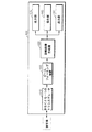
図3は、図1に示したビームフォーミング装置100の他の例を示した図面である。図3を参照すれば、ビームフォーミング装置100は、時間遅延値適用部105、保存部110、投影部115、加重値算出部120、加重値適用部130及び合成部130で構成される。
FIG. 3 is a view showing another example of the
図3に示したビームフォーミング装置100には、本実施形態に関する構成要素だけが示されている。従って、当業者ならば、図3に示した構成要素以外に、他の汎用的な構成要素がさらに含まれ得ることが分かるであろう。また、図3に示したビームフォーミング装置100の時間遅延値適用部105、投影部115、加重値算出部120及び合成部130は、一つ又は複数のプロセッサに対応する。
In the
図3に示したビームフォーミング装置100は、図1に示したビームフォーミング装置100の一実施形態に当たる。これにより、本実施形態によるビームフォーミング装置100は、図3に示したユニットに限定されない。また、図1に関連して記載した内容は、図3に示したビームフォーミング装置100にも適用可能であるので、重複説明は省略する。
The
ビームフォーミング装置100は、被写体から反射されたエコー信号を利用して受信ビームを形成する装置である。例えば、ビームフォーミング装置100は、数式1のような演算を行う。

数式1で、z[n]は、例えば深さ方向に異なる被写体の第n位置でビームフォーミングされた結果を表す信号である。この時、深さ方向の第n位置は、第n番目の焦点に対応し、ビームフォーミングされた結果によるz[n]は、ビームフォーミングされた結果によって形成された受信ビームに対応する。 In Equation 1, z [n] is a signal representing the result of beam forming at the nth position of a different object in the depth direction, for example. At this time, the nth position in the depth direction corresponds to the nth focus, and z [n] resulting from the beamforming corresponds to the received beam formed by the beamforming result.
Mは、ビームフォーミングに関与する受信チャネルの数又はビームフォーミングに関与する受信サブアレイの数となる。以下で、Mは、受信チャネルの数、mは、M個のチャネルのうち第mチャネルを表すが、これに限定されず、Mは、受信サブアレイの数、mは、M個のサブアレイのうち第mサブアレイを表す場合もある。 M is the number of reception channels involved in beamforming or the number of reception subarrays involved in beamforming. Hereinafter, M represents the number of reception channels, m represents the m-th channel among M channels, but is not limited thereto, M is the number of reception subarrays, and m is the number of M subarrays. It may represent the mth sub-array.
wm[n]は、第n位置で第mチャネルに適用されるビームフォーミング係数である。この時、ビームフォーミング係数は、アポダイゼーションウィンドウ、又は加重値となり、第mチャネルは、第mトランスデューサとなる。以下、このwm[n]を「加重値」という。 w m [n] is a beamforming coefficient applied to the m-th channel at the n-th position. At this time, the beamforming coefficient becomes an apodization window or a weight value, and the mth channel becomes the mth transducer. Hereinafter, this w m [n] is referred to as a “weighted value”.
xm[n]は、第n位置で反射し、第mチャネルに受信されたエコー信号であり、△m[n]は、第n位置から第mチャネルの位置までの距離によって、送信信号又は受信信号が伝達される時に補償される時間遅延値となる。これにより、xm[n−△m[n]]は、第n位置で反射し、第mチャネルを通じて受信され、時間遅延値が適用されたエコー信号である。
エコー信号の時間軸についてこのように時間遅延値△m[n]を考慮することにより、第n位置と第mチャネルの位置との間の距離による時間遅延値に起因する誤差がキャンセルされ、より高解像度の診断画像が得られる。
x m [n] is an echo signal reflected at the n-th position and received by the m-th channel, and Δ m [n] is a transmission signal or a signal depending on the distance from the n-th position to the position of the m-th channel. This is a time delay value that is compensated when the received signal is transmitted. Thus, x m [n−Δ m [n]] is an echo signal reflected at the n th position, received through the m th channel, and to which a time delay value is applied.
By considering the time delay value Δ m [n] in this way for the time axis of the echo signal, the error due to the time delay value due to the distance between the nth position and the mth channel position is canceled, and more A high-resolution diagnostic image can be obtained.
これにより、ビームフォーミング装置100は、複数のチャネルデータに対するエコー信号を利用して、一つのRFスキャンラインを構成する。また、ビームフォーミング装置100は、深さ方向による第n位置の相違を考慮して、被写体から反射されたエコー信号に各チャネル別に時間遅延値を適用し、時間遅延値が適用されたエコー信号に加重値を適用し、加重値が適用されたエコー信号を合成し、合成結果によって所定の位置nで反射する超音波信号を表す受信ビームを推定する。
Thereby, the
数式1をベクトル形式で表現すれば、数式2のように表現される。
数式2で、Z[n]は、ビームフォーミングされた結果、W[n]は、加重値、X△[n]は、時間遅延値が適用されたエコー信号を表し、上添字Hは、エルミート転置(Hermitian Transpose)、上添字Tは、転置(Transpose)を表す。 In Equation 2, Z [n] is a result of beam forming, W [n] is a weighted value, X Δ [n] is an echo signal to which a time delay value is applied, and the superscript H is Hermitian. Transposition (Hermitian Transpose), superscript T represents transposition.
このように、ビームフォーミング装置100は、被写体から反射されたエコー信号に時間遅延値及び加重値を適用し、受信ビームを形成する。この時、本実施形態によるビームフォーミング装置100は、加重値ベクトル空間の次元を低下することによって、解像度(この時の解像度は、最小分散法によって獲得されるレベルの解像度となる)に影響を殆ど及ぼさず、演算量を著しく減少できる。即ち、ビームフォーミング装置100は、複数の基底ベクトルを利用して加重値を算出するので、加重値ベクトル空間の次元を低減できる。
As described above, the
時間遅延値適用部105は、被写体から反射されたエコー信号に時間遅延値を適用する。本実施形態によるビームフォーミングのための時間遅延値は、焦点とトランスデューサとの距離による誤差を補正する時間遅延値となる。
この補正により、焦点とトランスデューサとの距離による時間遅延値に起因する誤差がキャンセルされ、より高解像度の診断画像が得られる。
The time delay
By this correction, the error due to the time delay value due to the distance between the focal point and the transducer is canceled, and a higher-resolution diagnostic image can be obtained.
数式1を参照して説明すれば、時間遅延値適用部105は、被写体から反射されたエコー信号xm[n]に時間遅延値△m[n]を適用して、xm[n−△m[n]]を出力する。このように、時間遅延値適用部105で時間遅延値が適用されたエコー信号xm[n−△m[n]]を、被写体の第n位置ごとにベクトル形式で表現すると、数式2のX△[n]となる。
If described with reference to Equation 1, the time delay
保存部110は、既測定のエコー信号のビームフォーミング係数から獲得された複数の基底ベクトルを保存する。この時、保存部110に保存される複数の基底ベクトルは、基底ベクトルの集合となる。
The
投影部115は、被写体から反射されたエコー信号を保存部110に保存された複数の基底ベクトルのうち、少なくとも一部の基底ベクトルの各々に投影する。この時、被写体から反射されたエコー信号xm[n]は、時間遅延値適用部105から出力される時間遅延値が適用されたエコー信号xm[n−△m[n]]となる。
The
投影部115で投影の対象となる少なくとも一部の基底ベクトルの数は、ユーザによって決定される。保存部110に40個の基底ベクトルが保存されている場合を例として説明すれば、投影部115は、時間遅延値が適用されたエコー信号を、ユーザの決定による40個以下の基底ベクトルの各々に投影する。
The number of at least some basis vectors to be projected by the
投影部115でエコー信号を、ユーザの決定による所定数の基底ベクトルに投影することによって、エコー信号の次元が低下される。
投影部115で行われる投影についてさらに詳細に説明すれば、数式2によるビームフォーミング結果は、数式3のように表現される。
The projection performed by the
数式3で、Zは、ビームフォーミング結果、X△は、時間遅延値が適用されたエコー信号、Uは、複数の基底ベクトル、αは、基底ベクトルに対する加重値となる。このように、本実施形態によるビームフォーミング装置100における加重値は、Uとαとの積、即ち、基底ベクトルの加重和と定義される。
In Equation 3, Z is a beamforming result, XΔ is an echo signal to which a time delay value is applied, U is a plurality of basis vectors, and α is a weighted value for the basis vectors. Thus, the weight value in the
また、数式3は、数式4のように整理される。
数式4で、X△Uは、時間遅延値が適用され、複数の基底ベクトルに投影されたエコー信号を表す。
さらに詳細に説明すれば、複数の基底ベクトルの集合を表す行列Uは、数式5のように定義される。
More specifically, a matrix U representing a set of a plurality of basis vectors is defined as
数式5で、Uは、複数の基底ベクトルの集合、Vは、アイゲンベクトル又は基底ベクトル、rは、ユーザによって決定される保存しようとする基底ベクトルの数となる。また、数式5で、基底ベクトルVは、固定型ウィンドウ(Fixed window)として機能する。
In
数式4及び数式5を参照すれば、時間遅延値が適用され、複数の基底ベクトルに投影されたエコー信号X△Uは、複数の基底ベクトルの集合Uに投影される。
Referring to
このように、ビームフォーミング装置100は、時間遅延値が適用され、基底ベクトルに投影されたエコー信号に加重値を積算してビームフォーミングを行う。これについて、副開口の個数が32であるエコー信号を10個の基底ベクトルに投影する場合を例として説明すれば、エコー信号の次数が、32から10に低下するにつれて、加重値を算出するために行われる演算量が著しく減少する。
As described above, the
また、投影部115は、ステアリングベクトル(Steering vector)を、保存部110に保存された複数の基底ベクトルのうち少なくとも一部の基底ベクトルの各々に投影する。この時、投影部115で投影の対象となる少なくとも一部の基底ベクトルの数は、ユーザによって決定される。これにより、投影部115は、修正されたステアリングベクトルを出力する。これについて、以下の数式6及び数式8を参照して詳細に説明する。
In addition, the
このように、ビームフォーミング装置100は、加重値を算出する演算量を減少させるために、時間遅延値が適用されたエコー信号を基底ベクトルに投影し、ステアリングベクトルを基底ベクトルに投影し、投影されたエコー信号及び投影されたステアリングベクトルを利用して加重値を算出する。
As described above, the
加重値算出部120は、保存部110に保存された複数の基底ベクトルを利用して、被写体から反射されたエコー信号に適用される加重値を算出する。例えば、加重値算出部120は、投影部115で投影されたエコー信号を利用して加重値を算出する。
The weight
例えば、加重値算出部120は、数式6のような演算を行って加重値を算出する。
数式6で、αは、加重値、R△Uは、X△Uの標本共分散行列(Sample Covariance matrix)、emは、修正されたステアリングベクトルとなる。 In Equation 6, alpha is a weighted value, R △ U is X △ sample covariance matrix U (Sample Covariance matrix), e m is a modified steering vector.
この時、加重値算出部120は、標本共分散行列(R△U)の逆行列である(R△U −1)を算出する際の計算の安定性(Stability)を保証するために、ダイアゴナルローディング(Diagonal Loading)技法又は軸スムージング(Axial smoothing)技法を使用できる。
At this time, the weight
数式6で、R△Uは、数式7によって定義され、emは、数式8によって定義される。
数式7で、標本共分散行列R△Uは、X△Uと転置したX△Uとの積に係わる期待値と定義される。この時、数式7の標本共分散行列R△Uは、X△Uをサブアレイ単位で処理して平均値を反映することによって、標本共分散行列R△Uを獲得することもできる。
数式8で修正されたステアリングベクトルemは、ステアリングベクトルeを基底ベクトルの集合Uに投影して獲得される。この時、ステアリングベクトルeは、トランスデューサから被写体に送信される信号の位相を制御するためのものである。これにより、ビームフォーミングに係わる時間遅延値が予め或る方向に対して適用されたと仮定すれば、ステアリングベクトルeは、1で構成される。 Steering vectors e m which is fixed in Equation 8 is obtained by projecting the steering vector e in the set U of basis vectors. At this time, the steering vector e is for controlling the phase of the signal transmitted from the transducer to the subject. Accordingly, if it is assumed that the time delay value related to beam forming is previously applied to a certain direction, the steering vector e is composed of 1.
これにより、加重値算出部120は、投影部115で基底ベクトルに投影されたエコー信号及び基底ベクトルに投影されたステアリングベクトルを利用して加重値を算出するので、演算量が著しく減少する。
As a result, the
合成部130は、保存部110に保存された複数の基底ベクトルを利用して、被写体から反射されたエコー信号に、加重値算出部120で算出された加重値を適用し、加重値が適用された信号を合成する。例えば、合成部130は、投影部115で投影されたエコー信号に、加重値算出部120で算出された加重値を適用する。
The
合成部130での加重値の適用は、数式3及び数式4で表現されたように、時間遅延値が適用され、複数の基底ベクトルに投影されたエコー信号X△Uに、加重値は、αを積算する場合を表すが、これに限定されない。
Application of the weight value in the
これにより、本実施形態による投影部115でエコー信号を複数の基底ベクトルに投影し、合成部130で投影されたエコー信号に加重値を適用することによって、ビームフォーミング装置100は、被写体から反射されたエコー信号に対してマルチウィンドウィング操作を行う。
Thus, the
また、合成部130は、加重値が適用された信号を合成する。合成部130の合成結果によって、数式1及び数式2で表現されたように、ビームフォーミングされた結果によって形成された受信ビームz[n]、即ち、Z[n]が出力される。
Further, the
これにより、本実施形態によるビームフォーミング装置100は、演算量が著しく減少したビームフォーミングを行える。
以下では、被写体から反射されたエコー信号が、M個のチャネルから受信される場合を例として、ビームフォーミング装置100でのビームフォーミングについてさらに詳細に説明するが、これに限定されず、被写体から反射されたエコー信号は、M個のサブアレイから受信される場合も同様である。
Thereby, the
In the following, beam forming in the
例えば、被写体から反射されたエコー信号Xは、数式9のように定義される。
数式9で、X1は、第1チャネルから受信されるエコー信号、X2は、第2チャネルから受信されるエコー信号、XMは、第Mチャネルから受信されるエコー信号となる。 In Equation 9, X 1 is, echo signals received from the first channel, X 2 is, echo signals received from the second channel, X M is a echo signals received from the M channel.
時間遅延値適用部105は、被写体から反射されたエコー信号Xに時間遅延値△を適用する。例えば、時間遅延値適用部105で時間遅延値が適用されたエコー信号X△は、数式10のように定義される。
数式10で、X△1は、時間遅延値△1が適用された第1チャネルから受信されるエコー信号、X△2は、時間遅延値△2が適用された第2チャネルから受信されるエコー信号、X△Mは、時間遅延値△Mが適用された第Mチャネルから受信されるエコー信号となる。
In
保存部110は、既測定のエコー信号のビームフォーミング係数から獲得された複数の基底ベクトルを保存する。例えば、保存部110に保存される複数の基底ベクトルは、基底ベクトルの集合となり、基底ベクトルの集合Uは、数式11のように定義される。
数式11で、V1は、第1基底ベクトル、V2は、第2基底ベクトル、Vrは、第r基底ベクトルとなる。この時、rは、ユーザによって決定可能であり、1以上の定数となる。 In Equation 11, V 1 is a first basis vector, V 2 is a second basis vector, and V r is an r-th basis vector. At this time, r can be determined by the user and is a constant of 1 or more.
投影部115は、被写体から反射されたエコー信号を保存部110に保存された複数の基底ベクトルのうち少なくとも一部の基底ベクトルの各々に投影する。
The
ユーザが保存部110に保存されたr個の基底ベクトルのうち、k個の基底ベクトルを利用してビームフォーミングを行う場合を例として説明する。この時、kは、ユーザによって決定可能であり、1以上の定数となる。また、kは、rより小さいか同じであり、Mより小さい。即ち、本実施形態によって使われる基底ベクトルの数は、チャネルの数より少ない。
An example will be described in which the user performs beam forming using k basis vectors among r basis vectors stored in the
これにより、投影部115から保存部110に保存された基底ベクトルのうち、k個の基底ベクトルに投影された時間遅延値が適用されたエコー信号X△Uは、数式12のように定義される。
数式12で、X△U1は、第1基底ベクトルV1に投影されたエコー信号、X△U2は、第2基底ベクトルV2に投影されたエコー信号、X△Ukは、第k基底ベクトルVkに投影されたエコー信号となる。 In Equation 12, X △ U1 an echo signal projected on the first basis vector V 1, X △ U2 is projected echo signal to the second basis vector V 2, X △ Uk is, the k basis vectors V The echo signal is projected onto k .
数式10及び数式12を参照すれば、被写体から反射されたエコー信号X△は、M次元を有するが、投影部115によって投影されたエコー信号X△Uは、k次元を有する。数式11及び数式12で説明したように、kは、M未満であるので、投影部115の投影によってエコー信号の次元が低下する。
Referring to
また、投影部115は、ステアリングベクトルを保存部110に保存された複数の基底ベクトルのうち少なくとも一部の基底ベクトルの各々に投影する。これにより、投影部115から保存部110に保存された基底ベクトルのうち、k個の基底ベクトルに投影されたステアリングベクトルemは、数式13のように定義される。
数式13で、em1は、第1基底ベクトルV1に投影されたステアリングベクトル、em2は、第2基底ベクトルV2に投影されたステアリングベクトル、emkは、第k基底ベクトルVkに投影されたステアリングベクトルとなる。 In Equation 13, e m1 is a steering vector projected onto the first basis vector V 1 , e m2 is a steering vector projected onto the second basis vector V 2 , and e mk is projected onto the kth basis vector V k . Steering vector.
加重値算出部120は、投影部115で投影されたエコー信号及び投影部115で投影されたエコー信号ステアリングベクトルを利用して加重値を算出する。例えば、加重値算出部120で算出された加重値は、数式14のように定義される。
数式14で、α1は、第1基底ベクトルV1に投影されたエコー信号に適用される加重値、α2は、第2基底ベクトルV2に投影されたエコー信号に適用される加重値、αkは、第k基底ベクトルVkに投影されたエコー信号に適用される加重値となる。この時、αkは、数式12のX△Uk及び数式13のemkを利用して算出される。 In Equation 14, α 1 is a weight applied to the echo signal projected onto the first basis vector V 1 , α 2 is a weight applied to the echo signal projected onto the second basis vector V 2 , α k is a weight value applied to the echo signal projected onto the k-th basis vector V k . At this time, α k is calculated using X ΔUk in Expression 12 and e mk in Expression 13.
合成部130は、時間遅延値が適用され、投影されたエコー信号に算出された加重値αTを適用し、加重値αTが適用された信号を合成する。例えば、合成部130で時間遅延値が適用され、複数の基底ベクトルに投影されたエコー信号X△Uに加重値αTを適用し、加重値αTが適用された信号を合算した結果は、数式15のように定義される。
これにより、合成部130で合算した結果は、ビームフォーミングによって形成された受信ビームとなる。
これにより、本実施形態によるビームフォーミング装置100は、診断画像の解像度を保証しつつも、演算量を低減したビームフォーミングを行える。
As a result, the result of the summation by the combining
Thereby, the
図4は、本発明の他の実施形態による医療画像システム400を示した図面である。図4を参照すれば、医療画像システム400は、ビームフォーミング装置100、少なくとも一つのトランスデューサ410、診断画像生成部420、表示部430、保存部440及び出力部450で構成される。
FIG. 4 is a diagram illustrating a
図4に示したビームフォーミング装置100は、図1及び図3に示したビームフォーミング装置100の一実施形態に当たる。これにより、図1乃至図3について記載した内容は、図4に示した医療画像システム400にも適用可能であるので、重複説明は省略する。
The
本実施形態による医療画像システム400は、被写体に対する診断画像を提供する。例えば、被写体を表す診断画像を表示するか、又は被写体を表す診断画像を表示する外部装置に被写体に対する診断画像を表す信号を出力する。この時、診断画像は例えば、超音波画像となるが、これに限定されない。
The
少なくとも一つのトランスデューサ410は、被写体及び信号を送受信する。本実施形態による少なくとも一つのトランスデューサ410は例えば、1次元アレイトランスデューサ(Array−Transducer)であるが、これに限定されず、2次元アレイトランスデューサ、3次元アレイトランスデューサともなる。
At least one
少なくとも一つのトランスデューサ410は、被写体に送信信号を送信し、被写体から反射されたエコー信号を受信する。
ビームフォーミング装置100は、既測定のエコー信号のビームフォーミング係数から獲得された複数の基底ベクトルを利用して、被写体から反射されたエコー信号に適用される加重値を算出し、被写体から反射されたエコー信号に前記算出された加重値を適用し、加重値が適用された信号を合成する。
At least one
The
この時、既測定のエコー信号のビームフォーミング係数から獲得された複数の基底ベクトルは、ビームフォーミング装置100に保存されるか、又は保存部440に保存される。これにより、ビームフォーミング装置100は、保存された複数の基底ベクトルのうち少なくとも一部を利用してビームフォーミングする。この時、少なくとも一部の基底ベクトルの数は、ユーザによって決定可能である。
At this time, a plurality of basis vectors acquired from the beamforming coefficients of the already measured echo signals are stored in the
このように、ビームフォーミング装置100は、複数の基底ベクトルを利用して加重値を算出し、算出された加重値を適用するので、減少した演算量でビームフォーミングを行える。
As described above, the
また、本実施形態による少なくとも一つのトランスデューサ410及びビームフォーミング装置100は、プローブ(Probe)に含まれるが、これに限定されず、ビームフォーミング装置100は、医療画像システム400の本体に含まれ、少なくとも一つのトランスデューサ410だけがプローブに含まれもする。
In addition, the at least one
診断画像生成部420は、ビームフォーミング装置100から出力された信号を利用して診断画像を生成する。診断画像生成部420は、DSP(Digital Signal Processor)(図示せず)及びDSC(Digital Scan Converter)(図示せず)を含む。本実施形態によるDSPは、ビームフォーミング装置100から出力された信号に対して所定の信号処理操作を行い、DSCは、所定の信号処理操作が行われた信号を利用して形成された画像データをスキャン変換して、診断画像を生成する。
The diagnostic
表示部430は、診断画像生成部420で生成された診断画像を表示する。例えば、表示部430は、医療画像システム400に設けられたディスプレイパネル、マウス、LCD(Liquid Crystal Display)画面、モニターなどの出力装置の何れかを含む。
但し、本実施形態による医療画像システム400は、表示部430を備えず、診断画像生成部420で生成された診断画像を外部の表示装置(図示せず)に出力するための出力部450を備える場合もあることが当業者であれば理解できるであろう。
However, the
保存部440は、診断画像生成部420で生成された診断画像及び医療画像システム400の動作中に発生するデータを保存する。本実施形態による保存部440は、通常の記録媒体からなり、保存部440は、ハードディスクドライブ(Hard Disk Drive:HDD)、ROM(Read Only Memory)、RAM(Random Access Memory)、フラッシュメモリ(Flash Memory)及びメモリカード(Memory Card)を何れかを含むことが当業者であれば理解できるであろう。
The
出力部450は、有無線ネットワーク又は有線直列通信を通じて外部装置とデータを送受信する。この時、ネットワークは、インターネット(Internet)、LAN(Local Area Network)、無線LAN(Wireless LAN)、WAN(Wide Area Network)、PAN(Personal Area Network)を含むが、これに限定されず、情報を送受信する他の種類のネットワークであってもよい。また、外部装置は例えば、遠隔地に位置した他の医療画像システム、汎用コンピュータシステム、ファクシミリの何れかである。
The
また、当業者ならば、本実施形態による保存部440及び出力部450は、画像判読及び検索機能をさらに含み、PACS(Picture Archiving Communication System)のような形態に一体化できることが分かるであろう。
Further, those skilled in the art will appreciate that the
これにより、本実施形態によるビームフォーミング装置100で、ビームフォーミングの実行に処理される演算量が多くないので、医療画像システム400は、リアルタイム高解像度診断画像が生成できる。
Thereby, since the amount of calculation processed for execution of beamforming is not large in the
図5は、本実施形態によるビームフォーミング方法を示したフローチャートである。図5を参照すれば、ビームフォーミング方法は、図1、図3及び図4に示したビームフォーミング装置100又は医療画像システム400で時系列的に処理されるステップで構成される。従って、図1、図3及び図4に示したビームフォーミング装置100又は医療画像システム400について説明した内容は以下では省略するけれども、図5のビームフォーミング方法にも適用できることが分かるであろう。
FIG. 5 is a flowchart illustrating the beamforming method according to the present embodiment. Referring to FIG. 5, the beamforming method includes steps processed in time series by the
501ステップで、加重値算出部120は、既測定のエコー信号のビームフォーミング係数から獲得された複数の基底ベクトルを利用して、被写体から反射されたエコー信号に適用される加重値を算出する。
In
502ステップで、合成部130は、既測定のエコー信号のビームフォーミング係数から獲得された複数の基底ベクトルを利用して、被写体から反射されたエコー信号に前記501ステップで算出された加重値を適用し、加重値が適用された信号を合成する。
In step 502, the
これにより、本実施形態によれば、リアルタイム高解像度診断画像を獲得するためのビームフォーミングを行える。 Thereby, according to this embodiment, beam forming for acquiring a real-time high-resolution diagnostic image can be performed.
一方、前述した方法は、コンピュータで実行されるプログラムに作成可能であり、コンピュータで読取可能な記録媒体を利用して、前記プログラムを動作させる汎用デジタルコンピュータで具現される。また、前述した方法で使われたデータの構造は、コンピュータで読取可能な記録媒体に複数の手段を通じて記録される。前記コンピュータで読取可能な記録媒体は例えば、マグネチック記録媒体(例えば、ROM(Read Only Memory)、フロッピー(登録商標)ディスク、ハードディスクなど)、光学的な判読媒体(例えば、CD−ROM、DVD(Digital Versatile Disk)など)の何れかである。 On the other hand, the above-described method can be created in a program executed by a computer, and is embodied by a general-purpose digital computer that operates the program using a computer-readable recording medium. The data structure used in the above-described method is recorded on a computer-readable recording medium through a plurality of means. Examples of the computer-readable recording medium include a magnetic recording medium (for example, a ROM (Read Only Memory), a floppy (registered trademark) disk, a hard disk, etc.), an optical reading medium (for example, a CD-ROM, a DVD ( Digital Versatile Disk)).
当業者ならば、上述の各種実施形態が前記記載の本質的な特性から離脱しない範囲で変形された形態でも具現できることが分かるであろう。開示した方法は、限定的な観点ではなく、説明的な観点で考慮されねばならない。本発明の範囲は、前述した説明にではなく、特許請求の範囲に表現されており、それと同等な範囲内にあるすべての差異は、本発明に含まれていると解釈されねばならない。 Those skilled in the art will appreciate that the various embodiments described above can be implemented in variations that do not depart from the essential characteristics described above. The disclosed methods should be considered in an illustrative rather than a limiting perspective. The scope of the present invention is expressed not in the above description but in the claims, and all differences within the equivalent scope should be construed as being included in the present invention.
本発明は、医療関連の技術分野に好適に適用可能である。 The present invention is suitably applicable to medical related technical fields.
21 アイゲンベクトルを示すグラフ
22 基底ベクトルを示すグラフ
100 ビームフォーミング装置
105 時間遅延値適用部
110,440 保存部
115 投影部
120 加重値算出部
130 合成部
400 医療画像システム
410 少なくとも一つのトランスデューサ
420 診断画像生成部
430 表示部
450 出力部
21 graph showing
Claims (17)
前記保存された複数の基底ベクトルを利用して、被写体から反射されたエコー信号に適用される加重値を算出する加重値算出部と、
前記保存された複数の基底ベクトルを利用して、前記被写体から反射されたエコー信号に前記算出された加重値を適用し、前記加重値が適用された信号を合成する合成部と、を備えることを特徴とするビームフォーミング装置。 A storage unit for storing a plurality of basis vectors obtained from the beamforming coefficients of the measured echo signal;
A weight calculating unit that calculates a weight applied to an echo signal reflected from a subject using the plurality of stored basis vectors;
A combining unit that applies the calculated weight value to an echo signal reflected from the subject using the plurality of stored basis vectors, and combines the signal to which the weight value is applied; A beam forming device characterized by this.
前記加重値算出部は、前記投影されたエコー信号を利用して加重値を算出し、
前記合成部は、前記投影されたエコー信号に前記算出された加重値を適用し、前記加重値が適用された信号を合成することを特徴とする請求項1に記載のビームフォーミング装置。 A projection unit that projects an echo signal reflected from a subject onto each of at least some of the stored basis vectors;
The weight calculation unit calculates a weight using the projected echo signal,
The beam forming apparatus according to claim 1, wherein the combining unit applies the calculated weight value to the projected echo signal and combines the signal to which the weight value is applied.
前記加重値算出部は、前記投影されたエコー信号及び前記投影されたステアリングベクトルを利用して加重値を算出し、
前記合成部は、前記投影されたエコー信号に前記算出された加重値を適用し、前記加重値が適用された信号を合成することを特徴とする請求項2に記載のビームフォーミング装置。 The projection unit projects a steering vector onto each of at least some of the stored basis vectors.
The weight calculation unit calculates a weight using the projected echo signal and the projected steering vector,
The beam forming apparatus according to claim 2, wherein the combining unit applies the calculated weight value to the projected echo signal, and combines the signal to which the weight value is applied.
前記ビームフォーミング装置から出力された信号を利用して診断画像を生成する診断画像生成部と、を備えることを特徴とする医療画像システム。 Using a plurality of basis vectors obtained from the beamforming coefficients of the measured echo signal, a weight value applied to the echo signal reflected from the subject is calculated, and the calculation is performed on the echo signal reflected from the subject. A beam forming apparatus that applies a weighted value and synthesizes a signal to which the weight is applied;
A medical image system, comprising: a diagnostic image generation unit that generates a diagnostic image using a signal output from the beam forming apparatus.
前記ビームフォーミング装置は、前記保存された複数の基底ベクトルのうち少なくとも一部を利用してビームフォーミングすることを特徴とする請求項7に記載の医療画像システム。 The medical imaging system further includes a storage unit that stores the plurality of basis vectors,
The medical image system according to claim 7, wherein the beam forming apparatus performs beam forming using at least a part of the stored plurality of basis vectors.
前記複数の基底ベクトルを利用して、前記被写体から反射されたエコー信号に前記算出された加重値を適用し、前記加重値が適用された信号を合成するステップと、を含むことを特徴とするビームフォーミング方法。 Calculating a weight value applied to an echo signal reflected from a subject using a plurality of basis vectors obtained from a beamforming coefficient of a measured echo signal;
Applying the calculated weight value to an echo signal reflected from the subject using the plurality of basis vectors, and synthesizing the signal to which the weight value is applied. Beam forming method.
前記加重値を算出するステップは、前記投影されたエコー信号を利用して加重値を算出し、
前記合成するステップは、前記投影されたエコー信号に前記算出された加重値を適用し、前記加重値が適用された信号を合成することを特徴とする請求項11に記載のビームフォーミング方法。 Projecting an echo signal reflected from a subject onto each of at least some of the plurality of basis vectors;
The step of calculating the weight value calculates the weight value using the projected echo signal,
12. The beamforming method according to claim 11, wherein the synthesizing step applies the calculated weight value to the projected echo signal and synthesizes the signal to which the weight value is applied.
前記加重値を算出するステップは、前記投影されたエコー信号及び前記投影されたステアリングベクトルを利用して加重値を算出することを特徴とする請求項12に記載のビームフォーミング方法。 Projecting a steering vector onto each of at least some of the plurality of basis vectors;
13. The beamforming method according to claim 12, wherein the step of calculating the weight value calculates the weight value using the projected echo signal and the projected steering vector.
A computer-readable recording medium storing a computer program for causing a computer to execute the method according to any one of claims 11 to 16.
Applications Claiming Priority (2)
| Application Number | Priority Date | Filing Date | Title |
|---|---|---|---|
| KR10-2011-0120315 | 2011-11-17 | ||
| KR1020110120315A KR101888649B1 (en) | 2011-11-17 | 2011-11-17 | Method for beamforming, apparatus and medical imaging system performing the same |
Publications (1)
| Publication Number | Publication Date |
|---|---|
| JP2013106957A true JP2013106957A (en) | 2013-06-06 |
Family
ID=47143645
Family Applications (1)
| Application Number | Title | Priority Date | Filing Date |
|---|---|---|---|
| JP2012253498A Pending JP2013106957A (en) | 2011-11-17 | 2012-11-19 | Beam forming device and method, medical image system performing the same, and computer-readable recoding medium |
Country Status (5)
| Country | Link |
|---|---|
| US (1) | US9161739B2 (en) |
| EP (1) | EP2594956B1 (en) |
| JP (1) | JP2013106957A (en) |
| KR (1) | KR101888649B1 (en) |
| CN (1) | CN103120594B (en) |
Cited By (4)
| Publication number | Priority date | Publication date | Assignee | Title |
|---|---|---|---|---|
| JP2015071028A (en) * | 2013-09-05 | 2015-04-16 | セイコーエプソン株式会社 | Ultrasonic measuring apparatus, ultrasonic image apparatus and ultrasonic measuring method |
| KR20160035526A (en) * | 2014-09-23 | 2016-03-31 | 삼성메디슨 주식회사 | Method and apparatus for generating ultrasonic image |
| KR20160046777A (en) * | 2016-04-14 | 2016-04-29 | 알피니언메디칼시스템 주식회사 | Beamformer, ultrasonic imaging apparatus and beam forming method |
| JP2016077907A (en) * | 2014-10-21 | 2016-05-16 | 愛飛紐医療機械貿易有限公司 | Beamforming device, ultrasonic imaging apparatus and beamforming method |
Families Citing this family (8)
| Publication number | Priority date | Publication date | Assignee | Title |
|---|---|---|---|---|
| KR102185415B1 (en) | 2013-01-11 | 2020-12-02 | 삼성전자주식회사 | Beam forming module, ultrasonic imaging apparatus using the same, method for beam forming using the beam forming module and method for controlling a ultrasonic imaging apparatus using the same |
| KR101832835B1 (en) | 2013-07-11 | 2018-02-28 | 삼성전자주식회사 | Imaging processing module, ultrasound imaging apparatus, method for beam forming and method for controlling a ultrasound imaging apparatus |
| KR101555267B1 (en) * | 2013-11-29 | 2015-09-24 | 알피니언메디칼시스템 주식회사 | Method And Apparatus for Beamforming by Using Unfocused Ultrasound |
| KR20150118734A (en) | 2014-04-15 | 2015-10-23 | 삼성전자주식회사 | Ultrasound imaging apparatus and control method for the same |
| KR102120796B1 (en) * | 2014-05-13 | 2020-06-09 | 삼성전자주식회사 | A beamforming apparatus, a method for forming beams, an ultrasonic imaging apparatus and an ultrasonic probe |
| CN107431272A (en) * | 2015-03-06 | 2017-12-01 | 何晓溪 | Beam form-endowing method and device |
| KR102040853B1 (en) * | 2015-03-27 | 2019-11-05 | 알피니언메디칼시스템 주식회사 | Beamforming apparatus, ultrasonic imaging apparatus and beamforming method capable of simple spatial smoothing operation |
| CN106842212B (en) * | 2017-03-31 | 2019-08-23 | 西安交通大学 | The quick self-adapted beam synthesizing method of multiple apodization based on Feature Space Decomposing |
Family Cites Families (8)
| Publication number | Priority date | Publication date | Assignee | Title |
|---|---|---|---|---|
| US6436044B1 (en) | 2000-02-14 | 2002-08-20 | Siemens Medical Solutions Usa, Inc. | System and method for adaptive beamformer apodization |
| DE10032426B4 (en) | 2000-07-04 | 2006-01-12 | Siemens Ag | Beamforming method |
| ITSV20000036A1 (en) | 2000-09-07 | 2002-03-07 | Esaote Spa | IMAGE DETECTION SYSTEM AND METHOD |
| US6527720B1 (en) | 2001-09-24 | 2003-03-04 | Acuson Corporation | Medical ultrasonic imaging method and system for spatial compounding |
| US8246544B2 (en) | 2004-01-08 | 2012-08-21 | Panasonic Corporation | Ultrasonic diagnosis apparatus |
| US20060173313A1 (en) | 2005-01-27 | 2006-08-03 | Siemens Medical Solutions Usa, Inc. | Coherence factor adaptive ultrasound imaging |
| KR100886932B1 (en) | 2007-06-26 | 2009-03-09 | 주식회사 바이오넷 | Multi Channel Beamformer using Single Interpolation |
| JP5560134B2 (en) * | 2010-08-03 | 2014-07-23 | 富士フイルム株式会社 | Ultrasonic image generator |
-
2011
- 2011-11-17 KR KR1020110120315A patent/KR101888649B1/en active IP Right Grant
-
2012
- 2012-10-31 EP EP12190824.8A patent/EP2594956B1/en active Active
- 2012-11-16 CN CN201210465077.7A patent/CN103120594B/en active Active
- 2012-11-19 JP JP2012253498A patent/JP2013106957A/en active Pending
- 2012-11-19 US US13/680,741 patent/US9161739B2/en active Active
Cited By (5)
| Publication number | Priority date | Publication date | Assignee | Title |
|---|---|---|---|---|
| JP2015071028A (en) * | 2013-09-05 | 2015-04-16 | セイコーエプソン株式会社 | Ultrasonic measuring apparatus, ultrasonic image apparatus and ultrasonic measuring method |
| KR20160035526A (en) * | 2014-09-23 | 2016-03-31 | 삼성메디슨 주식회사 | Method and apparatus for generating ultrasonic image |
| KR102270721B1 (en) | 2014-09-23 | 2021-06-30 | 삼성메디슨 주식회사 | Method and apparatus for generating ultrasonic image |
| JP2016077907A (en) * | 2014-10-21 | 2016-05-16 | 愛飛紐医療機械貿易有限公司 | Beamforming device, ultrasonic imaging apparatus and beamforming method |
| KR20160046777A (en) * | 2016-04-14 | 2016-04-29 | 알피니언메디칼시스템 주식회사 | Beamformer, ultrasonic imaging apparatus and beam forming method |
Also Published As
| Publication number | Publication date |
|---|---|
| EP2594956A1 (en) | 2013-05-22 |
| CN103120594A (en) | 2013-05-29 |
| KR20130054743A (en) | 2013-05-27 |
| CN103120594B (en) | 2017-05-24 |
| KR101888649B1 (en) | 2018-08-16 |
| EP2594956B1 (en) | 2017-08-23 |
| US9161739B2 (en) | 2015-10-20 |
| US20130131514A1 (en) | 2013-05-23 |
Similar Documents
| Publication | Publication Date | Title |
|---|---|---|
| JP2013106957A (en) | Beam forming device and method, medical image system performing the same, and computer-readable recoding medium | |
| US8666197B2 (en) | Method of generating image, apparatus for performing the same, diagnosis system, and medical image system | |
| JP2016077907A (en) | Beamforming device, ultrasonic imaging apparatus and beamforming method | |
| US10426443B2 (en) | Object information acquiring apparatus and control method for same | |
| US9261586B2 (en) | Method and apparatus for generating diagnosis image, diagnosis system, and medical image system for performing the method | |
| EP2702946B1 (en) | Object information acquisition apparatus and display method | |
| KR101792589B1 (en) | Beamformer, diagnosing system, medical image system and method for displaying diagnosing image | |
| US9442187B2 (en) | Object information obtaining apparatus, display method, and storage medium | |
| JP2012170826A (en) | Method and apparatus for forming ultrasonic beam, ultrasonic image system and computer-readable recording medium | |
| US10098613B2 (en) | Image processing module, ultrasound imaging apparatus, image processing method, and control method of ultrasound imaging apparatus | |
| KR102040853B1 (en) | Beamforming apparatus, ultrasonic imaging apparatus and beamforming method capable of simple spatial smoothing operation | |
| US9824680B2 (en) | Beamforming module, ultrasonic imaging apparatus using the same, beamforming method using the beamforming module, and method of controlling the ultrasonic imaging apparatus using the beamforming module | |
| Heyde et al. | Evaluation of the transverse oscillation technique for cardiac phased array imaging: A theoretical study | |
| KR20160046777A (en) | Beamformer, ultrasonic imaging apparatus and beam forming method | |
| Hyun | A universal end-to-end description of pulse-echo ultrasound image reconstruction | |
| Wang et al. | Generalized sidelobe canceller beamforming method for ultrasound imaging | |
| CN111133331A (en) | Method and system for filtering acoustic clutter and random noise | |
| Guenther et al. | Broadband optimal contrast resolution beamforming |