JP2013101101A - Mass distribution measurement method and mass distribution measurement device - Google Patents
Mass distribution measurement method and mass distribution measurement device Download PDFInfo
- Publication number
- JP2013101101A JP2013101101A JP2012202877A JP2012202877A JP2013101101A JP 2013101101 A JP2013101101 A JP 2013101101A JP 2012202877 A JP2012202877 A JP 2012202877A JP 2012202877 A JP2012202877 A JP 2012202877A JP 2013101101 A JP2013101101 A JP 2013101101A
- Authority
- JP
- Japan
- Prior art keywords
- mass distribution
- image
- mass
- ions
- irradiation
- Prior art date
- Legal status (The legal status is an assumption and is not a legal conclusion. Google has not performed a legal analysis and makes no representation as to the accuracy of the status listed.)
- Pending
Links
Images


Classifications
-
- H—ELECTRICITY
- H01—ELECTRIC ELEMENTS
- H01J—ELECTRIC DISCHARGE TUBES OR DISCHARGE LAMPS
- H01J49/00—Particle spectrometers or separator tubes
- H01J49/0004—Imaging particle spectrometry
-
- H—ELECTRICITY
- H01—ELECTRIC ELEMENTS
- H01J—ELECTRIC DISCHARGE TUBES OR DISCHARGE LAMPS
- H01J49/00—Particle spectrometers or separator tubes
-
- H—ELECTRICITY
- H01—ELECTRIC ELEMENTS
- H01J—ELECTRIC DISCHARGE TUBES OR DISCHARGE LAMPS
- H01J49/00—Particle spectrometers or separator tubes
- H01J49/02—Details
- H01J49/10—Ion sources; Ion guns
- H01J49/14—Ion sources; Ion guns using particle bombardment, e.g. ionisation chambers
- H01J49/142—Ion sources; Ion guns using particle bombardment, e.g. ionisation chambers using a solid target which is not previously vapourised
Abstract
Description
本発明は、試料上の物質をイオン化して、その物質の質量分析を行い、その物質の面内分布を画像化して出力するための方法及びそのために用いられる装置に関するものである。 The present invention relates to a method for ionizing a substance on a sample, performing mass analysis of the substance, imaging and outputting the in-plane distribution of the substance, and an apparatus used therefor.
生体組織を構成する多数の物質の分布情報を網羅的に可視化する分析方法として、質量分析法を応用したイメージング質量分析方法の開発が進んでいる。質量分析法とは、レーザー光や一次イオンを照射することによってイオン化した試料を質量電荷比によって分離し、質量電荷比とその検出強度とからなるスペクトルを得る方法である。試料表面を二次元的に質量分析することで、それぞれの質量電荷比に対応する物質の二次元的な検出強度の分布を得ることができ、各物質の分布情報を得る(質量イメージング)ことができる。 As an analysis method for comprehensively visualizing distribution information of a large number of substances constituting a living tissue, development of an imaging mass spectrometry method applying mass spectrometry is progressing. Mass spectrometry is a method of obtaining a spectrum comprising a mass-to-charge ratio and its detected intensity by separating a sample ionized by irradiation with laser light or primary ions according to the mass-to-charge ratio. By performing two-dimensional mass analysis of the sample surface, it is possible to obtain a two-dimensional detection intensity distribution of substances corresponding to each mass-to-charge ratio, and to obtain distribution information of each substance (mass imaging). it can.
質量分析法としては、試料をイオン化し、試料から検出器までの飛行時間の違いによってイオン化された対象物質を分離して検出する飛行時間型のイオン分析手段が主に用いられる。試料をイオン化する手段としては、パルス化され微細に収束されたレーザー光をマトリックスに混ぜて結晶化した試料に照射してイオン化するマトリックス支援レーザー脱離イオン化法(MALDI:Matrix Assisted Laser Desorption/Ionization)や、一次イオンビームを照射して試料をイオン化する二次イオン質量分析法(SIMS:Secondary Ion Mass Spectroscopy)が知られている。これらのうち、MALDIを利用したイメージング質量分析方法は、既にタンパク質や脂質等を含む生体試料の分析に広く利用されている。しかし、マトリクス結晶を利用するMALDI方式では空間分解能が原理上数十μm程度に制限されることから、サブミクロンの高い空間分解能を持つことができる飛行時間型二次イオン質量分析法(TOF-SIMS;Time Of Flight-Secondary Ion Mass Spectroscopy)も、近年注目を集めている。 As the mass spectrometry, a time-of-flight ion analysis unit that ionizes a sample and separates and detects the ionized target substance according to a difference in flight time from the sample to the detector is mainly used. Matrix Assisted Laser Desorption / Ionization (MALDI) is a means of ionizing a sample by irradiating and ionizing a crystallized sample by mixing a pulsed and finely focused laser beam into a matrix. In addition, secondary ion mass spectrometry (SIMS) is known in which a sample is ionized by irradiation with a primary ion beam. Among these, the imaging mass spectrometry method using MALDI has already been widely used for the analysis of biological samples containing proteins and lipids. However, in the MALDI method using a matrix crystal, the spatial resolution is limited to about several tens of μm in principle, so time-of-flight secondary ion mass spectrometry (TOF-SIMS) that can have a high spatial resolution of submicron. ; Time Of Flight-Secondary Ion Mass Spectroscopy) has also attracted attention in recent years.
これらの方法を用いた従来のイメージング質量分析方法では、イオン化用のビームを走査し、多数の微小な計測領域において逐次質量分析を行うことにより二次元分布情報を得ている。そのため、広い領域の質量イメージを得るには多大な時間を要するという課題がある。 In conventional imaging mass spectrometry methods using these methods, two-dimensional distribution information is obtained by scanning an ionization beam and sequentially performing mass analysis in a large number of minute measurement regions. Therefore, there is a problem that it takes a lot of time to obtain a mass image of a wide area.
この課題を解消するため、投影方式の質量分析装置が提案されている。この装置では、広い領域の構成成分を一括してイオン化し、このイオンを検出手段に投影することで、成分の質量情報と二次元的分布とを一度に取得することができるので、計測時間を大幅に短縮することが可能である。例えば特許文献1では、イオンの検出時間と検出位置とを同時に記録することで質量分析と二次元分布の検出とを同時に行うイメージング質量分析装置が開示されている。 In order to solve this problem, a projection-type mass spectrometer has been proposed. With this device, component information in a wide area is ionized in a lump, and by projecting these ions onto the detection means, the mass information and two-dimensional distribution of the components can be acquired at one time. It can be significantly shortened. For example, Patent Document 1 discloses an imaging mass spectrometer that simultaneously performs mass spectrometry and detection of a two-dimensional distribution by simultaneously recording ion detection time and detection position.
ところで、飛行時間型の質量分析装置では、質量分析部を形成するイオン光学系の軸が基板表面に対して垂直方向になるように配置されているのに対して、通常、イオン化用のビームは基板に対して斜めから入射される。 By the way, in the time-of-flight mass spectrometer, the ion optical system forming the mass analyzer is arranged so that its axis is perpendicular to the substrate surface. The light is incident on the substrate at an angle.
プローブとなるビームを基板に対して斜めに入射させる場合、基板や試料上に凹凸形状(以下、基板上の凹凸、又は単に凹凸ともいう)があると、その近傍にはビームの照射し得ない影となる領域が出現する。この領域では試料がイオン化されず、質量分析が行えない。これに対して、例えば、特許文献2の微分干渉顕微鏡では、直交する二つの方向から得た微分干渉画像を合成し、凹凸形状を有する欠陥を撮像する手段が開示されている。
When the probe beam is incident obliquely on the substrate, if there is an uneven shape on the substrate or sample (hereinafter referred to as unevenness on the substrate or simply referred to as unevenness), the beam cannot be irradiated in the vicinity of the uneven shape. A shadow area appears. In this region, the sample is not ionized and mass spectrometry cannot be performed. On the other hand, for example, the differential interference microscope of
従来のイメージング質量分析装置においては、イオン化ビームを基板面への入射角度によっては、基板上の凹凸近傍にはイオン化ビームが照射しない影が生じ、この領域の質量分布を正しく計測できないという課題があった。 In conventional imaging mass spectrometers, depending on the angle of incidence of the ionized beam on the substrate surface, there is a shadow that the ionized beam does not irradiate near the irregularities on the substrate, and the mass distribution in this region cannot be measured correctly. It was.
また、特許文献1に記載の質量分析装置のように、径が大きなイオン化ビームを用いる場合、上記課題に加えて、ビーム内の不均一性が質量分布の計測に顕著に影響を与えるという課題があった。 Moreover, when using an ionization beam with a large diameter as in the mass spectrometer described in Patent Document 1, in addition to the above-described problem, there is a problem that nonuniformity in the beam significantly affects the measurement of mass distribution. there were.
本発明は、イオン化ビームを基板上の試料表面に向けて照射し、発生したイオンの質量電荷比と検出位置とを含む情報を検出する二次元質量分布計測方法であって、更に、この試料表面にイオン化ビームを照射する方向を変化させる工程と、複数の照射方向からの照射による複数の質量分布画像を取得する工程と、これら複数の質量分布画像を合成する工程と、を有し、ここで、互いに異なった方向からイオン化ビームを照射して得られるこれらの複数の質量分布画像は、合成されるよりも以前に、試料上の各点の絶対座標と質量分布画像上のそれに対応する各点の座標を揃えるように回転変換されることを特徴とする、質量分布計測方法である。 The present invention is a two-dimensional mass distribution measurement method for irradiating a sample surface on a substrate with an ionization beam and detecting information including a mass-to-charge ratio of a generated ion and a detection position. Changing the direction in which the ionizing beam is irradiated, obtaining a plurality of mass distribution images by irradiation from a plurality of irradiation directions, and synthesizing the plurality of mass distribution images. The plurality of mass distribution images obtained by irradiating the ionized beam from different directions are obtained by combining the absolute coordinates of each point on the sample and the corresponding points on the mass distribution image before being synthesized. The mass distribution measurement method is characterized in that it is rotationally converted so as to align the coordinates.
本発明の質量分布計測方法によれば、複数のイオン化ビームの照射方向に対する複数の質量分布像を取得し、イオン化ビームの照射方向による画像の回転の影響を打ち消したうえでこれらの質量分布画像を合成し、再構成する。これにより、基板の形状に起因して生ずるイオン化ビームが照射されない影の影響、及び、広いイオン化ビームを使用した場合のビーム内の不均一性の影響を低減した、信頼性の高い質量イメージング画像を取得することが可能となる。 According to the mass distribution measurement method of the present invention, a plurality of mass distribution images with respect to the irradiation directions of a plurality of ionization beams are acquired, and after canceling the influence of image rotation due to the irradiation directions of the ionization beams, these mass distribution images are displayed. Synthesize and reconstruct. This makes it possible to obtain a reliable mass imaging image that reduces the influence of shadows that are not irradiated with the ionized beam due to the shape of the substrate and the effect of non-uniformity in the beam when a wide ionized beam is used. It can be acquired.
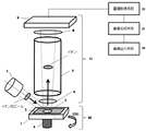
以下、本発明の方法及び本発明の方法に用いる装置の構成を、図1を用いて説明する。図1は、本発明の実施形態に係る方法を実施するための装置構成の概要を示すための模式図である。なお、これらの記載は本発明の一実施形態であり、本発明はこれに限定されるものではない。 Hereinafter, the configuration of the method of the present invention and the apparatus used for the method of the present invention will be described with reference to FIG. FIG. 1 is a schematic diagram for illustrating an outline of a device configuration for carrying out a method according to an embodiment of the present invention. In addition, these description is one Embodiment of this invention, and this invention is not limited to this.
本発明の質量分布計測装置は、イオン化ビームを基板2上の試料3の表面に向けて照射するイオン化ビーム照射手段1、及び、イオン検出手段11を備えている。更に、イオン化ビームを照射する方向を変化させる方向変化手段10と、複数の照射方向における複数の質量分布像を取得する画像取得手段12と、複数の質量分布像を合成する画像合成手段13と、を有している。
The mass distribution measuring apparatus of the present invention includes an ionized beam irradiation unit 1 that irradiates an ionized beam toward the surface of the sample 3 on the
イオン化法としては、エネルギービームを試料表面に入射させる方法であれば良く、イオン化ビームとしては、分析手法に応じて、イオン、レーザー光、中性粒子、電子等の中から選ばれる。このとき、MALDI等の方式等を採用することもできる。ただし、基板上の凹凸による影の影響は、高い空間分解能が得られる質量分析法を採用する場合により強調される。特にイオン化ビームとして一次イオンを用いたSIMS方式において本発明による効果はより顕著に見られる。また、イオン化ビームを試料表面に入射させる方法は限定されることはなく、いかなるものも使用することができる。走査型では、収束したイオン化ビームを照射し、投影型では試料の広い領域にイオン化ビームを照射する。投影方式は、走査方式と比較してより高い空間分解能が得られるため、本発明の効果が顕著にあらわれる。更に、質量分析部の構成を単純化することが容易であるため、本発明と親和性が高く、より好適に用いることができる。 The ionization method may be any method in which an energy beam is incident on the sample surface, and the ionization beam is selected from ions, laser light, neutral particles, electrons, and the like according to the analysis method. At this time, a method such as MALDI may be employed. However, the influence of the shadow due to the unevenness on the substrate is emphasized when a mass spectrometry that provides a high spatial resolution is employed. In particular, the effect of the present invention is more noticeable in the SIMS system using primary ions as the ionization beam. Further, the method for making the ionized beam incident on the sample surface is not limited, and any method can be used. In the scanning type, a focused ionization beam is irradiated, and in the projection type, a wide area of the sample is irradiated. Since the projection method can obtain a higher spatial resolution than the scanning method, the effect of the present invention is remarkably exhibited. Furthermore, since it is easy to simplify the configuration of the mass spectrometer, it has high affinity with the present invention and can be used more suitably.
試料3は固相であり、有機化合物、無機化合物、又は生体試料などを試料とすることができる。MALDIを採用する場合は、イオン化を補助する芳香族等の有機化合物を試料表面に添加して結晶化してもよい。試料は、およそ平坦な面を持つ基板2上に固定される。
Sample 3 is a solid phase, and an organic compound, an inorganic compound, a biological sample, or the like can be used as the sample. When employing MALDI, an organic compound such as an aromatic compound that assists ionization may be added to the sample surface for crystallization. The sample is fixed on the
また、質量分析方式としては特に限定されることなく、飛行時間型、磁場偏向型、四重極型、イオントラップ型、フーリエ変換イオンサイクロトロン共鳴型等の各種方式を採用することができる。イオン検出部に投影型を採用する場合は、飛行時間型の質量分析方式を用いることで、イオンの検出時間と検出位置を同時に記録することができる。 The mass spectrometry method is not particularly limited, and various methods such as a time-of-flight type, a magnetic field deflection type, a quadrupole type, an ion trap type, and a Fourier transform ion cyclotron resonance type can be employed. When the projection type is adopted for the ion detector, the ion detection time and the detection position can be recorded simultaneously by using a time-of-flight mass spectrometry.
以下、本発明の一実施態様として、イオン化ビームとして一次イオンを用い、飛行時間型の質量分析方式、及び、投影型の二次元一括方式を用いた構成について説明する。なお、以下の記載は本発明をこの構成に限定することを目的とするものではない。 Hereinafter, as one embodiment of the present invention, a configuration using a primary ion as an ionization beam and using a time-of-flight mass spectrometry method and a projection type two-dimensional batch method will be described. The following description is not intended to limit the present invention to this configuration.
図1は本実施形態に係る質量分布計測方法を実施するための装置を示す模式図である。イオン化ビームは、イオン化ビーム照射手段1から、射出方向に極めて短時間射出され、基板2上の試料3に照射される。即ち、イオン化ビームはパルス状に射出される。このパルス時間が長いと二次イオン発生時間の不確定性が増大し、質量分解能を低下させる。このため、例えばイオンビームを用いた場合、好ましくはパルスは1ns以下に設定される。また、イオン化ビームは基板2表面に対して斜めの方向から基板2、又は試料3に表面に入射する。
FIG. 1 is a schematic diagram showing an apparatus for carrying out the mass distribution measuring method according to the present embodiment. The ionization beam is emitted from the ionization beam irradiation means 1 in the emission direction for an extremely short time and is irradiated onto the sample 3 on the
一次イオンとしては、Bi+,Ga+などの液体金属系イオン、Bi3+,Au3+等の金属系のクラスターイオン、又はAr等のガス系のクラスターイオン等を用いることができる。クラスターイオンは有機物試料のダメージを軽減する効果がある。 As the primary ions, liquid metal ions such as Bi + and Ga + , metal cluster ions such as Bi 3+ and Au 3+ , gas cluster ions such as Ar, and the like can be used. Cluster ions have the effect of reducing damage to organic samples.
一般的な走査型のTOF-SIMSではイオンビームは1μm程度、又はそれ以下の径に収束して用いられる。これに対して、本実施形態で例示する投影型では、適度にデフォーカスされた、径の大きなイオンビームを用いる。一次イオンビームが試料上に照射された時の二次元的広がり、即ち一次イオン照射エリアは、計測エリアの大きさに応じて設定される。ここで言うイオンビームとは、進行方向に直交する方向に平面的に広がりのある、擬円盤状又は擬円筒状のイオン群である。生体試料において、複数の細胞を含むエリアを計測する場合は、一次イオン照射エリアは好ましくは数十μm〜1mm程度に設定される。 In general scanning type TOF-SIMS, the ion beam is converged to a diameter of about 1 μm or less. In contrast, the projection type exemplified in the present embodiment uses a large-diameter ion beam that is moderately defocused. The two-dimensional spread when the primary ion beam is irradiated onto the sample, that is, the primary ion irradiation area is set according to the size of the measurement area. The ion beam referred to here is a group of ions in a quasi-disc shape or a quasi-cylindrical shape that spreads in a plane perpendicular to the traveling direction. When measuring an area including a plurality of cells in a biological sample, the primary ion irradiation area is preferably set to about several tens of μm to 1 mm.
また、イオン化ビーム照射手段は、イオン照射位置を変位させる機能を有しており、イオン化ビームの照射位置の調整することができる。この変位機能は、後述のイオン化ビームの照射方向の変化と連動して変位させることもできる。例えば、照射位置を一定距離ずらし、その位置において照射方向を変えて質量分布画像を得ることができる。照射位置をずらした質量分布画像を重畳することで、イオン化ビームの不均一性の影響を緩和することができる。 The ionization beam irradiation means has a function of displacing the ion irradiation position, and can adjust the irradiation position of the ionization beam. This displacement function can be displaced in conjunction with a change in the irradiation direction of the ionized beam described later. For example, a mass distribution image can be obtained by shifting the irradiation position by a certain distance and changing the irradiation direction at that position. By superimposing the mass distribution images with the irradiation positions shifted, the influence of the non-uniformity of the ionized beam can be reduced.
基板2上に配置された試料3表面の任意の計測エリアに照射された一次イオンは、照射エリア全体にわたって一斉に二次イオンを発生させる。
Primary ions irradiated to an arbitrary measurement area on the surface of the sample 3 arranged on the
イオン検出手段11は、主には、引出電極6と、質量分析部7と、二次元イオン検出部(二次元検出手段)9によって構成される。質量mをもった二次イオンは、基板2と引出電極6との間に印加する電圧により加速される。二次イオンは試料3表面の二次イオン発生位置でのイオンの位置関係を保持したまま、質量分析部7を通過し、二次元イオン検出部9で検出される。
The ion detection means 11 is mainly composed of an extraction electrode 6, a
このとき、基板2又は基板2を固定する固定ホルダは接地され、引出電極6に数kV〜数10kVの正または負の電圧が印加される。なお、引出電極6の後段には、適宜投影型の光学系を構成する電極が配置される(不図示)。これらの電極は、二次イオンの空間的な広がりを抑制するための収束機能、及び、拡大機能を有する。このとき、拡大倍率は任意に設定される。
At this time, the
質量分析部7は、飛行管と呼ばれる筒状の質量分析管で構成される。飛行管内は等電位となっており、二次イオンは飛行管内を一定の速度で飛行する。飛行時間は、質量電荷比(m/z ; mは質量、zはイオンの価数)の平方根に比例することから、飛行時間を測定することで、発生した二次イオンの質量を分析することができる。
The
質量分析部7を通過した二次イオンは、二次元検出手段9に投影される。このとき、二次元検出手段9と質量分析部7の前に、投影倍率を調整するためのレンズを構成する投影調整電極8を配置しても良い。二次元検出手段9では、個々のイオンに関して、検出時刻と二次元検出器上での位置が関連付けられて出力される。なお、二次イオンの発生時刻と検出時刻との差から飛行時間が計測され、質量分析される。
The secondary ions that have passed through the
二次元検出手段9としては、イオンを検出した時刻と位置を検出できるものであれば、どのような構成でもよい。例えば、二次元検出手段9として、MCPと、蛍光板、及び、CCD(電荷結合素子)型等の二次元的光検出器を組み合わせた構成を選択することができる。高速のシャッタ機能を有するCCD型検出器を用いれば、撮像フレームごとに時間分割されたイオンを検出することで、質量分離することができる。 The two-dimensional detection means 9 may have any configuration as long as the time and position at which ions are detected can be detected. For example, as the two-dimensional detection means 9, a configuration combining a two-dimensional photodetector such as MCP, a fluorescent plate, and a CCD (charge coupled device) type can be selected. If a CCD detector having a high-speed shutter function is used, mass separation can be performed by detecting ions that are time-divided for each imaging frame.
なお、二次元検出器の代わりに単素子型の光検出器を配置すれば、走査型のイメージング質量分析装置の検出器を構成することも可能である。 Note that if a single-element photodetector is arranged instead of the two-dimensional detector, a detector of a scanning imaging mass spectrometer can be configured.
方向変化手段10は、基板2の方向を回転させる回転機構4を有することで、試料3に一次イオンを照射する方向を変化させることができる。このとき、本発明は、イオン化ビーム照射手段1、二次元検出手段9、及び方向変化手段10が装置本体に固定され、方向変化手段10により基板2が回転される構成である。或いは、基板2が装置本体に固定され、イオン化ビーム照射手段1が基板2に対して回転する構成を採用してもよい。図1には前者の構成を示すが、後者の構成を採用する場合、方向変化手段10はイオン化ビーム照射手段1を回転させることになる。または、同等の機能を持つが照射方向の異なる複数のイオン化ビーム照射手段を設けた構成を採用することも可能である。ただし、装置構成の複雑化を避け、小型化が可能になるという点で、基板が回転することによってイオン化ビームの照射方向を変化させる構成がより好ましい。
The direction changing means 10 has the rotating mechanism 4 that rotates the direction of the
方向変化手段10による基板2又はイオン化ビーム照射手段1の回転は、測定対象エリアの中心点を中心に行われる。この中心点は、質量分析部を形成するイオン光学系の中心軸と一致している。回転機構4の回転軸は、測定対象エリアの中心点と一致するように調整される。なお、回転機構4上には、基板2をXY方向に任意に変異させることのできる並進機構5が設置されることが好ましい。測定対象エリアを変化させる場合は、並進機構5を作動させる。並進機構5を併用することで、試料3上の任意の領域を測定対象に設定することができる。また、回転動作を行った場合に、試料3上の測定対象エリアが大きくずれることを回避することが容易になる。
The rotation of the
画像取得手段12は、二次元検出手段9から送られた、複数の照射方向からイオン化ビームを照射することにより得られる複数の質量分布像を取得し、各々のイオンの検出時間と検出位置に関する情報を基に、質量分布画像(以下、第1の質量分布画像という)を再構成する。このとき、ある時刻tから、微小時間Δt経過後の時刻t+Δtまでの間に検出されたイオンは、同じ質量電荷比を有するイオンとして認識し、イオン検出数を計数する。位置情報に対応させてイオン検出数を画像として出力することによって、あるイオンに関するイオン検出数分布、即ち第1の質量分布画像を構成することができる。同様の操作は、複数のm/zに対して行われる。なお、第1の質量分布画像は、イオン検出数分布でもよい。画像取得手段12は、上記方向変化手段10によってイオンの照射方向を複数の方向に変えるたびに、これらの複数の方向に対応した複数の第1の質量分布画像を取得する。 The image acquisition means 12 acquires a plurality of mass distribution images obtained by irradiating the ionized beam from a plurality of irradiation directions sent from the two-dimensional detection means 9, and information on the detection time and detection position of each ion Based on the above, a mass distribution image (hereinafter referred to as a first mass distribution image) is reconstructed. At this time, ions detected between a certain time t and a time t + Δt after the lapse of the minute time Δt are recognized as ions having the same mass-to-charge ratio, and the number of detected ions is counted. By outputting the number of detected ions in correspondence with the position information as an image, an ion detection number distribution relating to a certain ion, that is, a first mass distribution image can be constructed. A similar operation is performed for a plurality of m / z. The first mass distribution image may be an ion detection number distribution. The image acquisition means 12 acquires a plurality of first mass distribution images corresponding to a plurality of directions each time the direction changing means 10 changes the ion irradiation direction to a plurality of directions.
なお、本発明において質量分布像とは、二次元検出手段9により得られる質量電荷比やイオンの検出位置等の情報であり、質量分布画像を合成する際に用いられる情報を意味する。 In the present invention, the mass distribution image is information such as a mass-to-charge ratio and an ion detection position obtained by the two-dimensional detection means 9, and means information used when a mass distribution image is synthesized.
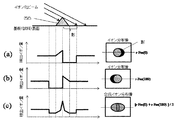
図2に示すように、このとき基板2に凹凸があると、一次イオンビームが照射されない影となる領域ができるため、画像上にも二次イオンが検出されない領域が影の様に描出される。
As shown in FIG. 2, if the
また、図3に示すように、基板上の凹凸近傍では、二次イオンが検出されない影の領域の出現位置はイオン照射方向に応じて変化する。ここで、試料に対する、回転前のイオン照射の入射方向と回転後のイオン照射の入射方向とが成す角度を、回転角θとする。この角度は、基板2平面へイオンが入射される方向(投影方向)と基板2面上の基準方向とが成す角度の変化量と言うこともできる。
In addition, as shown in FIG. 3, the appearance position of a shadow region where secondary ions are not detected changes in accordance with the ion irradiation direction in the vicinity of the unevenness on the substrate. Here, the angle formed by the incident direction of ion irradiation before rotation and the incident direction of ion irradiation after rotation with respect to the sample is defined as a rotation angle θ. This angle can also be said to be the amount of change in the angle formed by the direction in which ions are incident on the plane of the substrate 2 (projection direction) and the reference direction on the surface of the
本発明では、イオン化ビームの照射方向は、複数の方向が設定される。照射方向は任意に設定することができる。
例えば、二方向からイオンビームを照射する場合、互いの回転角の差が90°以上であれば、ほとんどの部分にイオン化ビームを照射することができる。そこで、ビームが照射されない部分を少なくするには、対向する方向、或いは対称な方向からイオン化ビームを照射することが好ましい。更に、二方向よりも多くの方向からイオン化ビームを照射することが好ましい。
In the present invention, a plurality of directions are set as the irradiation direction of the ionization beam. The irradiation direction can be set arbitrarily.
For example, when the ion beam is irradiated from two directions, the ionized beam can be irradiated to almost all parts as long as the difference between the rotation angles is 90 ° or more. Therefore, in order to reduce the portion where the beam is not irradiated, it is preferable to irradiate the ionized beam from the opposite direction or the symmetric direction. Furthermore, it is preferable to irradiate the ionized beam from more directions than two directions.
次に、画像合成手段13は、画像取得手段12が取得した質量分布画像のうち、異なる角度からイオンを照射することにより得られる複数の質量分布画像をもとに、一つの質量分布画像(以下、第2の質量分布画像、又は合成画像という)を構成し出力する。ここで、イオン化ビームの入射角度θにおける質量電荷比m/zのイオンについての第1の質量分布画像をFm(θ)とする。画像合成手段13は、イオン照射の入射方向と基板配置方向との成す角度が異なる複数の第1の質量分布画像をもとに、第2の質量分布画像Cfmを合成する(図3)。
Next, the image synthesizing means 13 is based on a plurality of mass distribution images obtained by irradiating ions from different angles among the mass distribution images acquired by the image acquisition means 12, and a single mass distribution image (hereinafter referred to as a mass distribution image). , A second mass distribution image or a composite image). Here, the first mass distribution image for ions with a mass-to-charge ratio m / z at the incident angle θ of the ionization beam is Fm (θ). The
より詳細には、画像合成手段13は、イオン照射の入射方向と基板2の配置方向との成す角度に応じて、第1の質量分布画像に対して回転変換操作を行い、試料上の各点の絶対座標と質量分布画像上でそれらに対応する各点の座標を揃えた上で、画像を合成する。例えば、回転角θに対して−θだけ質量分布画像を回転することにより、第1の質量分布画像を回転変換する。更に、上記回転変換操作を行って座標を揃えた複数の画像について、ピクセルごとに検出イオン数の平均を取ることにより、合成画像を得る。合成画像は画像出力手段14によって、第2の質量分布画像として表示又は出力される。以上のようにして、表面形状に由来する影の影響が打ち消され、イオンが検出されない領域が無い質量分布画像が得られる。
More specifically, the image synthesis means 13 performs a rotation conversion operation on the first mass distribution image according to the angle formed by the incident direction of ion irradiation and the arrangement direction of the
なお、画像取得手段12、画像合成手段13及び画像出力手段14は、専用の演算機能及びメモリを備えた集積回路等であってもよく、又は汎用のコンピュータ内にソフトウェアとして構築されたものであっても良い。
Note that the
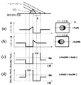
ところで、上記のように、画像回転操作を行い、単に平均を取ったのみでも影の影響を打ち消す十分な効果がある。しかし、更に影の影響を減らすには、以下の問題を解決する必要がある。即ち、得られた合成画像において、凹凸の周辺では、検出されるイオンの量が本来の値よりも小さくなる。この様子を、θ=0, 180の二方向の場合について、図4に示す。図4−(a)は、θ=0、即ち、紙面上左斜め上から一次イオンビームが照射された場合に得られる回転変換後のイオン分布像r-Fm(0)、及び検出イオン量の断面プロファイルである。また、図4−(b)は、θ=180、即ち、紙面上右斜め上から一次イオンビームが照射された場合に得られる回転変換後のイオン分布像r-Fm(180)、及び検出イオン量の断面プロファイルである。また、図4−(c)は、r-Fm(0)とr-Fm(180)の平均を取った合成イオン分布像、及び検出イオン量の断面プロファイルである。なお、イオンビームの入射方向を示す模式図は、イオンビームがθ=0、即ち、紙面上左斜め上から入射した場合のみ示す。 By the way, as described above, even if the image rotation operation is performed and the average is simply taken, there is a sufficient effect to cancel the influence of the shadow. However, in order to further reduce the influence of shadows, it is necessary to solve the following problems. That is, in the obtained composite image, the amount of ions detected is smaller than the original value around the unevenness. This state is shown in FIG. 4 for the case of θ = 0, 180 in two directions. Fig. 4- (a) shows θ = 0, that is, the ion distribution image r-Fm (0) after rotation conversion obtained when the primary ion beam is irradiated from the upper left corner of the paper, and the detected ion amount. It is a cross-sectional profile. FIG. 4- (b) shows θ = 180, that is, the ion distribution image r-Fm (180) after rotation conversion obtained when the primary ion beam is irradiated from the upper right side of the drawing, and the detected ions. A cross-sectional profile of the quantity. FIG. 4- (c) shows a synthetic ion distribution image obtained by averaging r-Fm (0) and r-Fm (180), and a cross-sectional profile of the detected ion amount. The schematic diagram showing the incident direction of the ion beam is shown only when the ion beam is incident from θ = 0, that is, from the upper left side of the drawing.
これに対して、以下に記す合成方法を用いて合成画像を形成することで、上記問題を回避することができる。 On the other hand, the above-mentioned problem can be avoided by forming a composite image using the composition method described below.
まず、画像合成手段13は、異なる回転角θで一次イオンを照射して得られた一対、又は複数の第1の質量分布画像を選択する。それぞれの質量分布画像について回転変換画像を得る。次に、回転変換画像を比較して、以下の判断と演算を行い、合成画像を形成する。このとき、影やイオン化ビームの不均一性等によりイオンが検出されないと判断された領域のピクセルの情報は採用せずに、いずれかの画像の相当する領域においてイオンが検出されたピクセルの情報を採用する。なお、ここでの情報とは、主にはイオン検出数に対応する画像情報を指すものとする。また、ここで、イオンが検出されないと判断された領域を抽出し、判断情報画像、即ち、影情報画像を形成する。 First, the image composition means 13 selects a pair or a plurality of first mass distribution images obtained by irradiating primary ions at different rotation angles θ. A rotation conversion image is obtained for each mass distribution image. Next, the rotation converted images are compared, and the following determination and calculation are performed to form a composite image. At this time, the pixel information of the pixel where the ion is detected in the corresponding region of any image is not used without adopting the pixel information of the region where the ion is not detected due to the shadow or the non-uniformity of the ionization beam. adopt. The information here mainly refers to image information corresponding to the number of detected ions. Also, here, a region where ions are determined not to be detected is extracted, and a determination information image, that is, a shadow information image is formed.
或いは、上記操作は以下の演算を行うと言うことができる。まず、回転変換画像において、イオンが検出されなかった(あるいはイオン検出数が所定の閾値以下であった)ピクセルを擬(ゼロ)に設定する。回転変換画像間で排他的論理和(一方の値のみが真である場合に演算結果を真とする)をとり、演算結果を排他的論理和画像とする。これらの画像で真値のピクセルは影の影響があったことを示す。即ち、排他的論理和画像は、影情報画像とみなすことができる。
次に、回転変換画像間で、各々のピクセル毎に演算を行い、合成画像を得る。このとき、排他的論理和画像において真値のピクセルに対応するアドレスでは、回転変換画像間の和を取る。一方、排他的論理和画像においてゼロ値に対応するアドレスでは、回転変換画像間の平均をとる。
Or it can be said that the said operation performs the following calculations. First, a pixel in which no ions are detected (or the number of detected ions is equal to or less than a predetermined threshold) is set to pseudo (zero) in the rotation conversion image. An exclusive OR is performed between the rotation-transformed images (when only one value is true, the operation result is true), and the operation result is an exclusive OR image. True pixels in these images indicate that there was a shadow effect. That is, the exclusive OR image can be regarded as a shadow information image.
Next, an operation is performed for each pixel between the rotation-converted images to obtain a composite image. At this time, at the address corresponding to the true value pixel in the exclusive OR image, the sum between the rotation converted images is calculated. On the other hand, at the address corresponding to the zero value in the exclusive OR image, the average between the rotation converted images is taken.
次に、前記選択された第1の質量分布画像とは異なった方向から一次イオンを照射して得られた一対、又は複数の第1の質量分布画像を選択する。この新たに選択された第1の質量分布画像についても上記と同様に合成画像を形成する。同様の操作を順次行って得られた複数の合成画像を平均化して、最終的な合成画像を形成することもできる。 Next, a pair or a plurality of first mass distribution images obtained by irradiating primary ions from a direction different from the selected first mass distribution image is selected. A composite image is also formed for the newly selected first mass distribution image in the same manner as described above. It is also possible to average a plurality of synthesized images obtained by sequentially performing the same operation to form a final synthesized image.
これら一連の処理によって、影の影響を大幅に低減した合成画像を得ることが可能となる。更には、広い照射面積を有する一次イオンの照射面内のイオン密度の不均一性による影響を緩和することも可能となる。 Through this series of processing, it is possible to obtain a composite image in which the influence of shadows is greatly reduced. Furthermore, it becomes possible to mitigate the influence of the non-uniformity of the ion density in the irradiation surface of the primary ions having a large irradiation area.
なお、これらの処理には、各照射により得られた第1の質量分布画像をそのまま使用してもよいが、同じ照射角度θについて第1の質量分布画像の平均化処理を先に行った後に、上記の一連の処理を行うことで、照射ごとのデータのばらつきによる影響を少なくすることができる。 In these processes, the first mass distribution image obtained by each irradiation may be used as it is, but after performing the averaging process of the first mass distribution image for the same irradiation angle θ first. By performing the above-described series of processing, it is possible to reduce the influence due to variation in data for each irradiation.
また、目的の試料成分のイオンだけではイオン検出量が十分でない場合は、以下の処理を行うことで補正演算を正しく行うことができる。まず、全イオン、十分な検出量が得られる一種のイオン、又は複数種のイオンの組み合わせを標準イオンとして採用する。標準イオンの情報に基づいて、画像ピクセル毎に影や一次イオンのイオン密度の不均一性の影響の有無を判断する。目的の試料成分のイオンについての質量分布画像に対して、対応するピクセル毎に標準画像に基いて行った判断結果を適用する。 Further, when the ion detection amount is not sufficient with only the ions of the target sample component, the correction calculation can be performed correctly by performing the following processing. First, all ions, one kind of ion that provides a sufficient detection amount, or a combination of a plurality of kinds of ions is adopted as a standard ion. Based on the information of the standard ions, the presence or absence of the influence of the nonuniformity of the ion density of the shadow and the primary ions is determined for each image pixel. The determination result based on the standard image is applied for each corresponding pixel to the mass distribution image of ions of the target sample component.
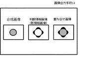
画像出力手段14は、合成画像を出力すると共に、画像ピクセル毎に行われた判断結果を画像化して、同時に出力する機能を有する。例えば、画像ピクセル毎に影か影でないかの判断結果を各々0または1で代表し、その数値をマップ化した判断情報画像を形成する。或いは、上述の排他的論理和画像を判断結果画像とすることもできる。画像出力手段は、合成画像と共に、判断情報画像を並べて表示することもできるし、或いは、これらを重ね合せた画像を表示することもできる。これにより、合成画像上のイオンカウント数の強度変位が試料の凹凸に起因するか否かを容易に知ることができる。 The image output means 14 has a function of outputting a composite image, imaging the determination result made for each image pixel, and outputting it simultaneously. For example, a determination result image is formed by representing the determination result for each image pixel as 0 or 1 and mapping the numerical value. Alternatively, the above-described exclusive OR image can be used as the determination result image. The image output means can display the determination information image side by side with the composite image, or can display an image obtained by superimposing these images. Thereby, it is possible to easily know whether or not the intensity displacement of the ion count number on the composite image is caused by the unevenness of the sample.
方向変化手段10による回転は、回転中心と計測対象エリアの中心とが一致するように制御される。また、回転中心は、二次イオン光学系の中心と一致するように制御される。θを変化させた画像の回転変換後の位置情報の正確な一致のためには、画像のパターンマッチング等の手法を用いると良い。より厳密に位置情報を一致させるためには、基板上に形成された位置合わせマーカーを基準にして画像位置情報を補正し、合成画像を形成してもよい。 The rotation by the direction changing means 10 is controlled so that the center of rotation coincides with the center of the measurement target area. The center of rotation is controlled to coincide with the center of the secondary ion optical system. In order to accurately match position information after rotational conversion of an image with changed θ, a method such as image pattern matching may be used. In order to match the position information more precisely, the composite image may be formed by correcting the image position information with reference to the alignment marker formed on the substrate.
このときマーカーは、予め基板上に形成しておいてもよいし、又は装置内にマーカー形成機構を設けておき、基板を装置内に導入した後、所定の領域にマーカーを形成してもよい。マーカー形成機構としては、例えば、収束イオンビーム蒸着によって金属の微小スポットを形成する手法等を用いることができる。 At this time, the marker may be formed on the substrate in advance, or a marker forming mechanism may be provided in the apparatus, and the marker may be formed in a predetermined region after the substrate is introduced into the apparatus. . As the marker formation mechanism, for example, a technique of forming a metal minute spot by focused ion beam evaporation can be used.
以下に、具体的な実施例を例示して本発明を説明するが、本発明はこれらの実施例に限定されるものではない。 Hereinafter, the present invention will be described with reference to specific examples, but the present invention is not limited to these examples.
以下の実施例において、基板回転角度がθのときに得られる第1の質量分布画像をF(θ)とする。また、全イオン分布をもとに得られる第1の質量分布画像をF0(θ)とし、ある質量電荷比(m/z)に関する第1の質量分布画像をFm(θ)とする。 In the following examples, the first mass distribution image obtained when the substrate rotation angle is θ is F (θ). Further, the first mass distribution image obtained based on the total ion distribution is F0 (θ), and the first mass distribution image related to a certain mass-to-charge ratio (m / z) is Fm (θ).
(実施例1)
本発明に係る第1の実施例を、図5及び図6を用いて説明する。図5は、本実施例における本発明の方法を実施するための装置の概略構成図である。
Example 1
A first embodiment according to the present invention will be described with reference to FIGS. FIG. 5 is a schematic configuration diagram of an apparatus for carrying out the method of the present invention in this embodiment.
基板2には導電性基板を用い、基板2上に、フォトリソプロセス等を用いて、方向を特定し得る突起パターンを形成しておく。基板2上に、薄片化した細胞形態を保持した生体試料等の試料3を配置する。
A conductive substrate is used as the
方向変化手段10は、回転機構4、及び並進機構5で構成される。並進機構5は、回転機構4上に配置され、回転軸に対して直交する方向に変位可能である。基板2は、並進機構5上に、基板2平面が回転機構4の回転軸に対して垂直になるように配置される。
The direction changing means 10 includes a rotation mechanism 4 and a
イオン化ビーム照射手段1が出力するビームとしては、一次イオンを用いる。一次イオンとしては、Ga+、Bi+等を使用する。ここでは、ビーム径が約500μmφにデフォーカスされた一次イオンビームを用いる。一次イオンビームは、数ns以下のパルス状に射出される。また、一次イオンビームは、その入射方向と基板2表面との成す角度が、45°に設定される。
As the beam output from the ionized beam irradiation means 1, primary ions are used. Ga <+> , Bi <+>, etc. are used as primary ions. Here, a primary ion beam defocused to a beam diameter of about 500 μmφ is used. The primary ion beam is emitted in a pulse shape of several ns or less. The angle formed between the incident direction of the primary ion beam and the surface of the
イオン検出手段11は、飛行時間型の質量分析部7と二次元イオン検出部9とを有する。測定領域は数百μm四方とし、質量分布画像の描画画素数は 256×256等に設定される。二次イオン引出電極6と基板2は数mm程度の間隔を持って配置され、これらの間には数kVの二次イオン引出電圧が印加される。
The ion detection means 11 includes a time-of-flight
次に、本発明の質量分布計測装置の動作について説明する。本実施例では、基板を90°毎に回転して計4方向から一次イオンビーム照射し、質量スペクトルを取得する。ただし、基板の回転角は任意に設定することができる。例えば、回転角を120°、或いは60°毎に回転させて、各々3方向、或いは6方向から一次イオンビームを照射するように設定しても良い。回転機構4が回転することによって、一次イオン照射方向を変えながら、各回転方向について複数回(数回〜数万回)の一次イオンビーム照射、及び二次イオンの計測を行う。 Next, the operation of the mass distribution measuring apparatus of the present invention will be described. In this embodiment, the substrate is rotated every 90 °, and the primary ion beam is irradiated from a total of four directions to obtain a mass spectrum. However, the rotation angle of the substrate can be set arbitrarily. For example, the rotation angle may be rotated every 120 ° or 60 ° so that the primary ion beam is irradiated from three directions or six directions, respectively. By rotating the rotation mechanism 4, the primary ion beam irradiation and the measurement of secondary ions are performed a plurality of times (several to tens of thousands) in each rotation direction while changing the primary ion irradiation direction.
次に、本実施例における画像合成処理について説明する。画像取得手段12は、二次元イオン検出部9で取得した位置及び質量に関するデータをメモリ上に出力する。さらに画像取得手段12は、このデータから基板の回転角度に対応する特定の質量電荷比(m/z)の信号についての第1の質量分布画像を構成し、メモリ上に出力する。 Next, image composition processing in the present embodiment will be described. The image acquisition means 12 outputs data relating to the position and mass acquired by the two-dimensional ion detector 9 on the memory. Further, the image acquisition means 12 constructs a first mass distribution image for a signal of a specific mass-to-charge ratio (m / z) corresponding to the rotation angle of the substrate from this data, and outputs it on the memory.
次に、画像合成手段13は、質量分布画像に対して、基板2の回転角度θに応じて画像処
理により回転変換を行う。このとき、基板2上面から見て、基板2を角度θ回転させた場合の第1の質量分布画像F(θ)に対しては、−θ回転の変換処理を行う。同様の処理を、全ての基板回転角度に関して、同じ質量電荷比を有する信号について行う。最後に、回転変換した全イオン画像を重ねあわせて平均化処理を行い、合成画像を構成する。画像出力手段14は合成画像を表示、又は出力する。
Next, the
上記処理により、合成画像においては、基板の凹凸により一次イオンが入射しない影の影響が顕著に低減される。一方、凹凸部以外の領域においても、一次イオンの不均一性の影響が顕著に改善される。以上のように、本実施例の質量分布計測装置によって、一次イオン入射方向依存性の小さい、良好な質量分布画像が得られる。 By the above processing, in the synthesized image, the influence of the shadow where the primary ions are not incident due to the unevenness of the substrate is remarkably reduced. On the other hand, the influence of the non-uniformity of the primary ions is remarkably improved also in the region other than the uneven portion. As described above, the mass distribution measuring apparatus of the present embodiment can obtain a good mass distribution image with small dependency on the primary ion incident direction.
(実施例2)
本発明に係る、第2の実施例を、図7を用いて説明する。本実施例においては、実施例1と、画像合成処理が異なる。本実施例で用いる装置構成は、実施例1と共通するため、説明を省略する。
(Example 2)
A second embodiment according to the present invention will be described with reference to FIG. In the present embodiment, the image composition processing is different from that in the first embodiment. Since the apparatus configuration used in this embodiment is the same as that of the first embodiment, description thereof is omitted.
本実施例では、基板2を90°ずつ回転し、計4方向からイオンビーム照射する。なお、基板2の回転角は任意に設定することができるが、互いに180°異なる回転角での計測が行われるように一対の角度が設定されることが好ましい。即ち、ここでは、基板回転角度θ(単位;度)としたとき、θ=0、180の組、及びθ=90、270の組が設定される。
In this embodiment, the
質量分布計測装置は、上記複数の回転方向について各々複数回の測定を行い、イオン検出位置、及び質量電荷比についてのデータを保存する。各方向について一連の計測が完了してから、更に基板2を回転し、同様の計測を繰り返す。ただし、基板の回転とイオン照射の順序はこれに限定されるものではなく、例えば、一回のイオン照射及び計測のたびに基板を回転させて、一照射方向(回転角度)につき複数の計測が行われるようにしてもよい。
The mass distribution measurement device performs measurement a plurality of times for each of the plurality of rotation directions, and stores data on the ion detection position and the mass-to-charge ratio. After a series of measurements is completed for each direction, the
画像取得手段12は、各基板回転角度θにおいて取得された位置情報を伴う質量スペクトル情報から、代表となる質量電荷比を持つ信号についての第1の質量分布画像を構成し、さらに基板の回転角度に応じて画像の回転変換を行う。図7−(a)は、θ=0、即ち、紙面上左斜め上から一次イオンビームが照射された場合に得られる回転変換後のイオン分布像及び断面プロファイルである。また、図7−(b)は、θ=180、即ち紙面上右斜め上から一次イオンビームが照射された場合に得られる回転変換後のイオン分布像、及び、断面プロファイルである。 The image acquisition means 12 constructs a first mass distribution image for a signal having a representative mass-to-charge ratio from mass spectrum information with position information acquired at each substrate rotation angle θ, and further, the rotation angle of the substrate Rotation conversion of the image is performed according to. FIG. 7- (a) shows an ion distribution image and a cross-sectional profile after rotation conversion obtained when θ = 0, that is, when the primary ion beam is irradiated from the upper left side of the drawing. FIG. 7 (b) shows an ion distribution image after rotation conversion and a cross-sectional profile obtained when θ = 180, that is, when the primary ion beam is irradiated obliquely from the upper right on the paper surface.
画像合成手段13は、以下に示す方法で、合成画像を構成する。まず、一対の画像r-F0(0)、r- F0(180)に対して、以下の処理を行う。r-F0(0)と、r-F0(180)をピクセル毎に比較して、共に信号強度がゼロ以下であった場合は、該等するピクセルはイオン信号が無いと判断する。この判断結果を第1の参照テーブルに記憶する。同様に、別の一対の画像r-F0(90)、r-F0(270)においても、上記と同様の判断を行い、判断結果を第2の参照テーブルに記憶する。 The image synthesizing means 13 constructs a synthesized image by the following method. First, the following processing is performed on the pair of images r-F0 (0) and r-F0 (180). When r-F0 (0) and r-F0 (180) are compared for each pixel and both signal intensities are less than or equal to zero, it is determined that the corresponding pixel has no ion signal. The determination result is stored in the first reference table. Similarly, for another pair of images r-F0 (90) and r-F0 (270), the same determination as above is performed, and the determination result is stored in the second reference table.
次に、それぞれの画像における対応する領域毎にイオンカウント比 R1= r-F0(0)/r-F0(180)、及びR2 = r-F0(180)/r-F0(0)を求める(図7−(c), (d))。なお、分母が負数であった場合、イオンカウント比には絶対値を用いるものとする。ここで、イオンカウント比についてしきい値Rthを設定する。なお、ここでは例としてRthを 100とするが、合成画像の状態に応じて設定を変更することができる。イオンビームが照射されなかった影の領域では検出イオン量が極端に低くなるため、除算をした結果の値は逆に極端に大きくなると考えられる。そのため、除算の結果が任意に設定したしきい値を超える領域については、分母になっている画像を取得する際にイオンビームが照射されない影となったため、検出イオン量が低くなった領域であると推定することができる。 Next, ion count ratios R1 = r−F0 (0) / r−F0 (180) and R2 = r−F0 (180) / r−F0 (0) are obtained for each corresponding region in each image ( Fig. 7 (c), (d)). If the denominator is a negative number, an absolute value is used for the ion count ratio. Here, a threshold value Rth is set for the ion count ratio. In this example, Rth is set to 100 as an example, but the setting can be changed according to the state of the composite image. Since the detected ion amount is extremely low in the shadow area where the ion beam is not irradiated, the value resulting from the division is considered to be extremely large. Therefore, the region where the result of division exceeds the arbitrarily set threshold is a region where the detected ion amount is low because it becomes a shadow that is not irradiated with the ion beam when acquiring the image as the denominator. Can be estimated.
R1がRthを超えた領域が存在する場合、画像r-F0(180)のその領域はイオンビームが照射されない影となったためイオンがカウントされなかったと判断し、画像r-F(0)の情報を採用する。ここで、領域とは、試料上の位置に対応する画像のピクセルのアドレスを指す。また、逆に、R2がRthを超えた領域は、画像r-F(180)の情報を採用する。また、それ以外の領域は、r-F(0)とr-F(180)の平均情報を採用する。なお、イオン信号がないと判断されたピクセルに関しては、ここで行う影の有無の判断からは除外する。これらの判断結果を第1の参照テーブルに記憶する。次に、別の一対の画像r-F0(90)、r-F0(270)においても、上記と同様の判断を行い、判断結果を第2の参照テーブルに記憶する。 If there is a region where R1 exceeds Rth, the region of image r-F0 (180) is judged not to have been counted because it is a shadow that is not irradiated with the ion beam, and the information from image rF (0) is used. To do. Here, the region refers to the address of the pixel of the image corresponding to the position on the sample. Conversely, for the region where R2 exceeds Rth, the information of image r-F (180) is adopted. For other areas, average information of r-F (0) and r-F (180) is adopted. Note that pixels determined to have no ion signal are excluded from the determination of the presence or absence of a shadow performed here. These determination results are stored in the first reference table. Next, for another pair of images r-F0 (90) and r-F0 (270), the same determination as above is performed, and the determination result is stored in the second reference table.
Rthは、信号強度とノイズの値によって、以下のように設定することができる。まず、複数の画素を含む評価領域を設定し、その領域の信号に対して、信号の平均値、信号のゆらぎ、又はノイズを抽出する。信号の平均値をμ、標準偏差をσとする。μ≧10σの場合、Rthは(μ+3σ)/(μ-3σ)<Rth<(μ-3σ)/3σの範囲で設定する。更には、この範囲内でより大きい値に設定することが好ましい。ただし、μ<10σのように信号に対して比較的ノイズが大きい場合には、正確な判断を行うことが困難であるが、Rthとして 1〜3の範囲の値を設定することは可能である。なお、μ及びσの抽出には、周波数解析等を併用することができる。例えば生体試料の場合では、細胞のスケールよりも小さい周期の信号をノイズとみなすなどの手法を取ることができる。 Rth can be set as follows according to the signal intensity and the noise value. First, an evaluation region including a plurality of pixels is set, and an average value of the signal, signal fluctuation, or noise is extracted from the signal in the region. Let the mean value of the signal be μ and the standard deviation be σ. When μ ≧ 10σ, Rth is set in the range of (μ + 3σ) / (μ-3σ) <Rth <(μ-3σ) / 3σ. Furthermore, it is preferable to set a larger value within this range. However, if the noise is relatively large for the signal such as μ <10σ, it is difficult to make an accurate judgment, but it is possible to set a value in the range of 1 to 3 as Rth . In addition, frequency analysis etc. can be used together for extraction of μ and σ. For example, in the case of a biological sample, it is possible to take a technique such as considering a signal having a period smaller than the cell scale as noise.
上記判断は、全質量画像を基に行ったが、検出カウント数の多い特定の1又は複数の質量電荷比に関するイオンを標準イオンとし、この標準イオンについての画像を基に行ってもよい。 The above determination is made on the basis of the total mass image. However, an ion relating to one or more specific mass-to-charge ratios having a large detection count may be used as a standard ion, and the determination may be made on the basis of an image of this standard ion.
次に、任意の質量電荷比(m/z)のイオンに関して、上記第1及び第2の参照テーブルを用いて、以下のように画像合成を行う。 Next, with respect to ions having an arbitrary mass-to-charge ratio (m / z), image synthesis is performed as follows using the first and second reference tables.
任意の質量電荷比の画像について、一対の画像r-Fm(0)、r-Fm(180)を選択し、第1の参照テーブルを参照する。合成画像に置ける画素ごとに、影となったと判断された領域のデータは採用せずに、合成画像CFm1を出力する。このとき、イオンが検出されなかった領域については双方の画像におけるその領域のイオン検出数の和をとり、それ以外の領域では双方の画像におけるその領域のイオン検出数の平均をとってもよい。次に、一対の画像r-Fm(90)、r-Fm(270)を選択し、第2の参照テーブルを参照して、同様の情報選択操作を行い、合成画像CFm2を出力する。次に、画像CFm1、CFm2の平均を取った合成画像CFmを出力する。また、信号がないと判断された領域のデータとしてはゼロ値を採用する。 For an image having an arbitrary mass-to-charge ratio, a pair of images r-Fm (0) and r-Fm (180) are selected, and the first reference table is referenced. For each pixel that can be placed in the composite image, the composite image CFm1 is output without using the data of the area determined to be a shadow. At this time, for a region where no ions are detected, the sum of the number of detected ions in that region in both images may be taken, and in other regions, the average number of detected ions in that region in both images may be taken. Next, a pair of images r-Fm (90) and r-Fm (270) are selected, a similar information selection operation is performed with reference to the second reference table, and a composite image CFm2 is output. Next, a composite image CFm obtained by averaging the images CFm1 and CFm2 is output. In addition, a zero value is adopted as the data of the area determined to have no signal.
合成画像CFmにおいては、基板上の凹凸により一次イオンが入射しない影の影響が顕著に低減される。一方、凹凸部以外の領域においても、一次イオンの不均一性の影響が顕著に改善される。以上のように、本実施例の質量分布計測装置によって、一次イオン入射方向依存性の小さい、良好な質量分布画像が得られる。 In the composite image CFm, the influence of the shadow where the primary ions do not enter is remarkably reduced due to the unevenness on the substrate. On the other hand, the influence of the non-uniformity of the primary ions is remarkably improved also in the region other than the uneven portion. As described above, the mass distribution measuring apparatus of the present embodiment can obtain a good mass distribution image with small dependency on the primary ion incident direction.
第1の参照テーブル或いは第2の参照テーブルに基き、画像ピクセル毎に影か影でないかの判断結果を各々0または1で代表し、その数値をマップ化した判断結果画像を形成する。図8に示すように、画像出力手段14は、合成画像Cfmと共に、判断情報画像(ここでは影情報画像)を並べた画像およびこれらを重ね合せた画像の少なくとも一方を表示する。図8では、4方向からのイオンビーム照射で影になる領域が重ね合せられて表示されているが、1方向からのイオンビーム照射について影になる領域のみ表示させても良い。これにより、合成画像上のイオンカウント分布と凹凸の有無を容易に対比させることができる。 Based on the first reference table or the second reference table, each image pixel is represented by 0 or 1 as a result of determination as to whether it is a shadow or not, and a determination result image in which the numerical values are mapped is formed. As shown in FIG. 8, the image output means 14 displays at least one of an image in which determination information images (shadow information images in this case) are arranged and an image in which these images are superimposed together with the composite image Cfm. In FIG. 8, regions that are shaded by ion beam irradiation from four directions are superimposed and displayed, but only regions that are shaded by ion beam irradiation from one direction may be displayed. Thereby, it is possible to easily compare the ion count distribution on the composite image with the presence or absence of unevenness.
(実施例3)
本実施例においては、実施例2と、画像合成における処理が一部異なる。装置構成は共通するため、説明を省略する。本実施例に置いては、一次イオンの照射角度θが異なる質量分布像を逐次比較し、合成画像を形成する。
(Example 3)
This embodiment is partially different from the second embodiment in the process of image composition. Since the apparatus configuration is common, the description is omitted. In this embodiment, mass distribution images with different primary ion irradiation angles θ are sequentially compared to form a composite image.
ここでは三方向から一次イオンを照射するため、θ=0、120、240 (単位;度)を設定する。各々のθについて、質量分布画像を取得し、回転変換を行ってr-F0(θ)を構成する。 Here, θ = 0, 120, and 240 (unit: degree) are set to irradiate primary ions from three directions. For each θ, a mass distribution image is acquired and subjected to rotational transformation to construct r-F0 (θ).
まず、r-F0(0)とr-F0(120)を比較する。比較の方法は、実施例2における、r-F0(0)とr-F0(180)との比較と基本的には同じである。比較結果を第1の参照テーブルに保存する。第1の参照テーブルに基いて、合成画像CFm1を出力する。 First, r-F0 (0) and r-F0 (120) are compared. The comparison method is basically the same as the comparison between r-F0 (0) and r-F0 (180) in the second embodiment. The comparison result is stored in the first reference table. Based on the first reference table, the composite image CFm1 is output.
次に、合成画像CFm1とr-F0(240)とを上記と同様に比較して、比較結果を第2の参照テーブルに保存する。第2の参照テーブル2に基いて、合成画像CFmを出力する。なお、θの値をより多く設定し、多方向から一次イオンビームを照射する場合でも、同様の処理を逐次行うことで合成画像CFmが得られる。 Next, the composite image CFm1 and r-F0 (240) are compared in the same manner as described above, and the comparison result is stored in the second reference table. Based on the second reference table 2, the composite image CFm is output. Even when a larger value of θ is set and the primary ion beam is irradiated from multiple directions, the composite image CFm can be obtained by sequentially performing the same processing.
(実施例4)
本実施例においては、実施例2と、画像合成における処理が一部異なる。他の処理や用いる装置構成は共通するため、説明を省略する。
Example 4
This embodiment is partially different from the second embodiment in the process of image composition. Since other processes and the apparatus configuration to be used are common, description is omitted.
画像合成手段13は、任意の質量電荷比の画像について、すべてのθに関する画像r-Fm(θ1)〜r-Fm(θ4)を画像ピクセルごとに比較する。ここで、最も大きなイオンカウント数に相当する情報を有する画像の情報を選択し、合成画像の相当するアドレスのピクセル値として採用する。
The
上記処理によっても、合成画像においては、基板上の凹凸により一次イオンが入射しない影の影響が顕著に低減される。一方、凹凸部以外の領域においても、一次イオンの不均一性の影響が顕著に改善される。以上のように、本実施例の質量分布計測装置によって、一次イオン入射方向依存性の小さい、良好な質量分布画像が得られる。 Also by the above processing, in the synthesized image, the influence of the shadow where the primary ions are not incident due to the unevenness on the substrate is remarkably reduced. On the other hand, the influence of the non-uniformity of the primary ions is remarkably improved also in the region other than the uneven portion. As described above, the mass distribution measuring apparatus of the present embodiment can obtain a good mass distribution image with small dependency on the primary ion incident direction.
1 イオン化ビーム照射手段
2 基板
3 試料
4 回転機構
5 並進機構
6 引出電極
7 質量分析部
8 投影調整電極
9 二次元イオン検出部
10 方向変化手段
11 イオン検出手段
12 画像取得手段
13 画像合成手段
14 画像出力手段
DESCRIPTION OF SYMBOLS 1 Ionized beam irradiation means 2 Substrate 3 Sample 4
Claims (11)
該試料表面にイオン化ビームを照射する方向を変化させる工程と、
複数の照射方向からの照射による複数の質量分布画像を取得する工程と、
該複数の質量分布画像を合成する工程と、を有し、ここで、
互いに異なった方向からイオン化ビームを照射して得られる該複数の質量分布画像は、合成される前に、試料上の各点の絶対座標と質量分布画像上のそれに対応する各点の座標を揃えるように回転変換されることを特徴とする、質量分布計測方法。 A mass distribution measurement method for detecting information including a mass-to-charge ratio of a generated ion and a detection position by irradiating an ionized beam toward a sample surface on a substrate,
Changing the direction of irradiating the sample surface with the ionization beam;
Acquiring a plurality of mass distribution images by irradiation from a plurality of irradiation directions;
Synthesizing the plurality of mass distribution images, wherein:
The plurality of mass distribution images obtained by irradiating ionized beams from different directions align the absolute coordinates of each point on the sample and the corresponding points on the mass distribution image before being synthesized. The mass distribution measurement method is characterized by being rotationally converted as described above.
前記検出位置は、試料表面で発生したイオンのイオン発生位置での位置関係を保持したまま検出され、前記質量電荷比は、発生したイオンの飛行時間を測定することで求められることを特徴とする、請求項1または2に記載の質量分布計測方法。 The ionization beam is an ionization beam that is two-dimensionally spread and pulsed;
The detection position is detected while maintaining a positional relationship of ions generated on the sample surface at the ion generation position, and the mass-to-charge ratio is obtained by measuring a time of flight of the generated ions. The mass distribution measuring method according to claim 1 or 2.
該試料表面にイオン化ビームを照射する方向を変化させる方向変化手段と、
複数の照射方向からの照射により検出された情報のそれぞれから複数の質量分布画像を
取得する画像取得手段と、
該複数の質量分布画像を合成する画像合成手段と、を有し、更に、
該画像合成手段は、互いに異なった方向からイオン化ビームを照射して得られる複数の該質量分布画像について、回転変換により試料上の各点の絶対座標と画像上でそれらに対応する各点の座標を揃えた上で合成画像を形成することを特徴とする、質量分布計測装置。 A mass distribution measuring device comprising an ionization beam irradiation means for irradiating an ionized beam toward a sample surface on a substrate, and an ion detection means for detecting information including a mass-to-charge ratio of ions generated by irradiation of the ionization beam and a detection position. There,
Direction changing means for changing the direction of irradiating the sample surface with the ionization beam;
Image acquisition means for acquiring a plurality of mass distribution images from each of the information detected by irradiation from a plurality of irradiation directions;
Image combining means for combining the plurality of mass distribution images, and
The image synthesizing means, with respect to a plurality of mass distribution images obtained by irradiating ionized beams from different directions, the absolute coordinates of each point on the sample and the coordinates of each corresponding point on the image by rotational transformation A mass distribution measuring device characterized by forming a composite image after aligning the two.
該試料表面にイオン化ビームを照射する方向を変化させる方向変化手段と、
複数の照射方向からの照射により検出された情報のそれぞれから複数の質量分布画像を
取得する画像取得手段と、
該複数の質量分布画像を合成する画像合成手段と、を有し、更に、
該画像合成手段は、互いに異なった方向からイオン化ビームを照射して得られる複数の該質量分布画像について、回転変換により試料上の各点の絶対座標と画像上でそれらに対応する各点の座標を揃えた上で合成画像を形成し、更に、
該画像合成手段は、該複数の質量分布画像を比較することで、一の質量分布画像における影又はイオン化ビームの不均一性によりイオンが検出されない領域を判断し、該判断情報を画像化した判断情報画像を形成し、
該合成画像と該判断情報画像を同時に表示する画像出力手段を備えたことを特徴とする、質量分布計測装置。 A mass distribution measuring device comprising an ionization beam irradiation means for irradiating an ionized beam toward a sample surface on a substrate, and an ion detection means for detecting information including a mass-to-charge ratio of ions generated by irradiation of the ionization beam and a detection position. There,
Direction changing means for changing the direction of irradiating the sample surface with the ionization beam;
Image acquisition means for acquiring a plurality of mass distribution images from each of the information detected by irradiation from a plurality of irradiation directions;
Image combining means for combining the plurality of mass distribution images, and
The image synthesizing means, with respect to a plurality of mass distribution images obtained by irradiating ionized beams from different directions, the absolute coordinates of each point on the sample and the coordinates of each corresponding point on the image by rotational transformation To form a composite image,
The image synthesis means compares the plurality of mass distribution images to determine a region where ions are not detected due to shadows or non-uniformity of the ionization beam in one mass distribution image, and the determination information is imaged. Forming an information image,
A mass distribution measuring apparatus comprising image output means for simultaneously displaying the composite image and the judgment information image.
試料表面に対して互いに異なった方向からイオン化ビームを照射して複数の質量分布画像を得る工程と、
試料上の各点の絶対座標と質量分布画像上のそれに対応する各点の座標を揃えるように前記複数の質量分布画像を変換する工程と、
変換した前記複数の画像情報を重ねて表示する工程と、
を有することを特徴とする画像取得方法。 An image acquisition method for acquiring a composite image in which the influence of unevenness on a sample surface is reduced,
Irradiating an ionized beam from different directions to the sample surface to obtain a plurality of mass distribution images;
Transforming the plurality of mass distribution images so as to align the absolute coordinates of each point on the sample and the coordinates of each corresponding point on the mass distribution image;
Displaying the converted plurality of pieces of image information in an overlapping manner;
An image acquisition method comprising:
Priority Applications (2)
| Application Number | Priority Date | Filing Date | Title |
|---|---|---|---|
| JP2012202877A JP2013101101A (en) | 2011-10-12 | 2012-09-14 | Mass distribution measurement method and mass distribution measurement device |
| US13/632,615 US8637808B2 (en) | 2011-10-12 | 2012-10-01 | Mass distribution measuring method and mass distribution measuring apparatus |
Applications Claiming Priority (3)
| Application Number | Priority Date | Filing Date | Title |
|---|---|---|---|
| JP2011225019 | 2011-10-12 | ||
| JP2011225019 | 2011-10-12 | ||
| JP2012202877A JP2013101101A (en) | 2011-10-12 | 2012-09-14 | Mass distribution measurement method and mass distribution measurement device |
Publications (2)
| Publication Number | Publication Date |
|---|---|
| JP2013101101A true JP2013101101A (en) | 2013-05-23 |
| JP2013101101A5 JP2013101101A5 (en) | 2015-11-05 |
Family
ID=48085361
Family Applications (1)
| Application Number | Title | Priority Date | Filing Date |
|---|---|---|---|
| JP2012202877A Pending JP2013101101A (en) | 2011-10-12 | 2012-09-14 | Mass distribution measurement method and mass distribution measurement device |
Country Status (2)
| Country | Link |
|---|---|
| US (1) | US8637808B2 (en) |
| JP (1) | JP2013101101A (en) |
Cited By (2)
| Publication number | Priority date | Publication date | Assignee | Title |
|---|---|---|---|---|
| WO2016129026A1 (en) * | 2015-02-09 | 2016-08-18 | 株式会社日立製作所 | Mirror ion microscope and ion beam control method |
| JP2017511571A (en) * | 2014-04-02 | 2017-04-20 | ザ ボード オブ トラスティーズ オブ ザ レランド スタンフォード ジュニア ユニバーシティー | Apparatus and method for submicron elemental image analysis by mass spectrometry |
Families Citing this family (3)
| Publication number | Priority date | Publication date | Assignee | Title |
|---|---|---|---|---|
| JP5885474B2 (en) * | 2011-11-17 | 2016-03-15 | キヤノン株式会社 | Mass distribution analysis method and mass distribution analyzer |
| KR102257901B1 (en) | 2014-09-19 | 2021-05-31 | 삼성전자주식회사 | Semiconductor inspection system and a method of inspecing a semiconductor device using the same |
| EP3290913B1 (en) * | 2016-09-02 | 2022-07-27 | ION-TOF Technologies GmbH | Secondary ions mass spectroscopic method, system and uses thereof |
Citations (5)
| Publication number | Priority date | Publication date | Assignee | Title |
|---|---|---|---|---|
| JP2007157353A (en) * | 2005-11-30 | 2007-06-21 | Osaka Univ | Imaging mass spectrometer |
| WO2007116509A1 (en) * | 2006-04-07 | 2007-10-18 | Shimadzu Corporation | Mass spectrometer |
| JP2009025275A (en) * | 2007-07-24 | 2009-02-05 | Shimadzu Corp | Mass analyzer |
| WO2010113209A1 (en) * | 2009-03-31 | 2010-10-07 | 株式会社島津製作所 | Mass spectrometry device |
| US20100255602A1 (en) * | 2007-03-01 | 2010-10-07 | Felton James S | Imaging Mass Spectrometer With Mass Tags |
Family Cites Families (4)
| Publication number | Priority date | Publication date | Assignee | Title |
|---|---|---|---|---|
| JP3471882B2 (en) | 1994-03-08 | 2003-12-02 | キヤノン株式会社 | Scanning atomic force microscope |
| US7064318B2 (en) * | 2003-08-26 | 2006-06-20 | Thermo Finnigan Llc | Methods and apparatus for aligning ion optics in a mass spectrometer |
| JP2007086610A (en) | 2005-09-26 | 2007-04-05 | Lasertec Corp | Differential interference microscope and defect inspecting device |
| EP2534475A4 (en) | 2010-02-08 | 2017-04-19 | Canon Kabushiki Kaisha | Method and apparatus for reducing noise in mass signal |
-
2012
- 2012-09-14 JP JP2012202877A patent/JP2013101101A/en active Pending
- 2012-10-01 US US13/632,615 patent/US8637808B2/en not_active Expired - Fee Related
Patent Citations (5)
| Publication number | Priority date | Publication date | Assignee | Title |
|---|---|---|---|---|
| JP2007157353A (en) * | 2005-11-30 | 2007-06-21 | Osaka Univ | Imaging mass spectrometer |
| WO2007116509A1 (en) * | 2006-04-07 | 2007-10-18 | Shimadzu Corporation | Mass spectrometer |
| US20100255602A1 (en) * | 2007-03-01 | 2010-10-07 | Felton James S | Imaging Mass Spectrometer With Mass Tags |
| JP2009025275A (en) * | 2007-07-24 | 2009-02-05 | Shimadzu Corp | Mass analyzer |
| WO2010113209A1 (en) * | 2009-03-31 | 2010-10-07 | 株式会社島津製作所 | Mass spectrometry device |
Non-Patent Citations (1)
| Title |
|---|
| JPN6014009261; 内藤 康秀: '「生体試料を対象にした質量顕微鏡」' Journal of the Mass Spectrometry Society of Japan Vol. 53, No. 3, 20050601, p. 125-132, 日本質量分析学会 * |
Cited By (3)
| Publication number | Priority date | Publication date | Assignee | Title |
|---|---|---|---|---|
| JP2017511571A (en) * | 2014-04-02 | 2017-04-20 | ザ ボード オブ トラスティーズ オブ ザ レランド スタンフォード ジュニア ユニバーシティー | Apparatus and method for submicron elemental image analysis by mass spectrometry |
| WO2016129026A1 (en) * | 2015-02-09 | 2016-08-18 | 株式会社日立製作所 | Mirror ion microscope and ion beam control method |
| US10304657B2 (en) | 2015-02-09 | 2019-05-28 | Hitachi, Ltd. | Mirror ion microscope and ion beam control method |
Also Published As
| Publication number | Publication date |
|---|---|
| US8637808B2 (en) | 2014-01-28 |
| US20130092831A1 (en) | 2013-04-18 |
Similar Documents
| Publication | Publication Date | Title |
|---|---|---|
| JP6668408B2 (en) | System and method for SEM overlay measurement | |
| US9136089B2 (en) | Pattern dimension measuring device, charged particle beam apparatus, and computer program | |
| JP6666627B2 (en) | Charged particle beam device and method of adjusting charged particle beam device | |
| JP5603421B2 (en) | Charged particle beam equipment with automatic aberration correction method | |
| JP2013101101A (en) | Mass distribution measurement method and mass distribution measurement device | |
| US20150115149A1 (en) | Mass distribution measurement method and mass distribution measurement apparatus | |
| US11067391B2 (en) | Charged particle beam device and sample thickness measurement method | |
| US10553391B2 (en) | SEM image acquisition device and SEM image acquisition method | |
| US9401297B2 (en) | Electrostatic chuck mechanism and charged particle beam apparatus | |
| US10446366B1 (en) | Imaging technique in scanning transmission charged particle microscopy | |
| US20150115148A1 (en) | Mass distribution measurement method and mass distribution measurement apparatus | |
| US20140224979A1 (en) | Mass distribution spectrometry method and mass distribution spectrometer | |
| US7800062B2 (en) | Method and system for the examination of specimen | |
| KR101748525B1 (en) | A method for analyzing material distribution of target surface and a system for the same | |
| JP4537891B2 (en) | Circuit pattern inspection apparatus and inspection method | |
| JP2014127224A (en) | Analyzer | |
| US9734985B2 (en) | Analytical apparatus, sample holder and analytical method | |
| JP7105321B2 (en) | Charged particle beam device | |
| EP3809443A1 (en) | Systems and methods of profiling charged-particle beams | |
| JP3715236B2 (en) | Method for measuring the concentration distribution in the depth direction of a sample by secondary ion mass spectrometry | |
| CN115335950A (en) | System and method for electronic detection of signals | |
| WO2023099104A1 (en) | Beam position displacement correction in charged particle inspection | |
| WO2024002798A1 (en) | Calibration of digital analog converter to control deflectors in charged particle beam system | |
| TW202323776A (en) | Method and apparatus for monitoring beam profile and power | |
| JP5530811B2 (en) | Scanning electron microscope |
Legal Events
| Date | Code | Title | Description |
|---|---|---|---|
| RD05 | Notification of revocation of power of attorney |
Free format text: JAPANESE INTERMEDIATE CODE: A7425 Effective date: 20130701 |
|
| A521 | Request for written amendment filed |
Free format text: JAPANESE INTERMEDIATE CODE: A523 Effective date: 20150911 |
|
| A621 | Written request for application examination |
Free format text: JAPANESE INTERMEDIATE CODE: A621 Effective date: 20150911 |
|
| A977 | Report on retrieval |
Free format text: JAPANESE INTERMEDIATE CODE: A971007 Effective date: 20160616 |
|
| A131 | Notification of reasons for refusal |
Free format text: JAPANESE INTERMEDIATE CODE: A131 Effective date: 20160621 |
|
| A02 | Decision of refusal |
Free format text: JAPANESE INTERMEDIATE CODE: A02 Effective date: 20161215 |