JP2013090217A - Radio base station - Google Patents

Radio base station Download PDF

Info

Publication number
JP2013090217A
JP2013090217A JP2011230117A JP2011230117A JP2013090217A JP 2013090217 A JP2013090217 A JP 2013090217A JP 2011230117 A JP2011230117 A JP 2011230117A JP 2011230117 A JP2011230117 A JP 2011230117A JP 2013090217 A JP2013090217 A JP 2013090217A
Authority
JP
Japan
Prior art keywords
port
base station
coupler
signal
input
Prior art date
Legal status (The legal status is an assumption and is not a legal conclusion. Google has not performed a legal analysis and makes no representation as to the accuracy of the status listed.)
Pending
Application number
JP2011230117A
Other languages
Japanese (ja)
Inventor
Hiromi Yasujima
弘美 安島
Yuichi Tanaka
裕一 田中
Current Assignee (The listed assignees may be inaccurate. Google has not performed a legal analysis and makes no representation or warranty as to the accuracy of the list.)
Kyocera Corp
Original Assignee
Kyocera Corp
Priority date (The priority date is an assumption and is not a legal conclusion. Google has not performed a legal analysis and makes no representation as to the accuracy of the date listed.)
Filing date
Publication date
Application filed by Kyocera Corp filed Critical Kyocera Corp
Priority to JP2011230117A priority Critical patent/JP2013090217A/en
Publication of JP2013090217A publication Critical patent/JP2013090217A/en
Pending legal-status Critical Current

Links

Images

Abstract

PROBLEM TO BE SOLVED: To provide a radio base station in which uplink signals from remote base stations are propagated to a centralized base station without losing signal strength.SOLUTION: A radio base station 100 comprises a centralized base station 101 and remote base stations 103a and 103b. A first coupler 107 has a first and a second input/output port composed of N lines of ports, in which a signal for any line of port of the first input/output port is branched from the second input/output port before being output, and a signal for any line of port of the second input/output port is branched from the first input/output port before being output. A second coupler 109 outputs a signal for a first port P5 from a second port P6, and outputs a signal for a third port P7 from the first port P5. The N remote base stations are respectively connected to the first input/output port, and a port P4 of the second input/output port is connected to the first port P5, in which a remaining port P3 of the second input/output port and the second port P6 are connected to an uplink signal processing unit 117.

Description

本発明は、無線基地局に関するものである。   The present invention relates to a radio base station.

近年、集中基地局(CS:Central Station又はBDE:Base station Digital Equipment)と複数の遠隔基地局(BS:Base Station又はRRE:Remote Radio Equipment)とを備え、集中基地局と遠隔基地局とが光ファイバ伝送路を介して接続されている光張り出し無線基地局が注目されている。集中基地局は、デジタル信号処理機能、保守監視機能などを備え、遠隔基地局のセル間の無線リソース制御を一括して行う。遠隔基地局は、アンテナを介した電波の送受信機能などを備えている。つまり、遠隔基地局は、独立基地局の無線部(RE:Radio Equipment)に相当するものであり、無線部のみの設置により通信エリアの拡張が図れる。   In recent years, a central base station (CS: Central Station or BDE: Base station Digital Equipment) and a plurality of remote base stations (BS: Base Station or RRE: Remote Radio Equipment) have been provided. Attention is focused on an optically protruding radio base station connected via a fiber transmission line. The centralized base station has a digital signal processing function, a maintenance monitoring function, and the like, and collectively performs radio resource control between cells of the remote base station. The remote base station has a function of transmitting / receiving radio waves via an antenna. That is, the remote base station corresponds to a radio unit (RE: Radio Equipment) of the independent base station, and the communication area can be expanded by installing only the radio unit.

従来、光張り出し無線基地局に関する種々の技術が提案されている(例えば、特許文献1参照)。特許文献1には、SCM(Subcarrier Multiplexing:サブキャリア多重)伝送方式を用いたROF(Radio Over Fiber:光ファイバ無線)システムが記載されている。遠隔基地局(子局装置)は複数のアンテナを有し、MIMO(Multiple Input Multiple Output)が採用されている。遠隔基地局は、複数のアンテナに対応する無線信号を多重化して、一本の光ファイバで集中基地局(親基地局)に伝送する。遠隔基地局は複数存在し、それぞれ集中基地局にスター状に光ファイバで接続されている。   Conventionally, various techniques relating to an optical extension radio base station have been proposed (see, for example, Patent Document 1). Patent Document 1 describes an ROF (Radio Over Fiber) system using an SCM (Subcarrier Multiplexing) transmission system. The remote base station (slave station device) has a plurality of antennas and employs MIMO (Multiple Input Multiple Output). The remote base station multiplexes radio signals corresponding to a plurality of antennas and transmits them to a centralized base station (parent base station) using a single optical fiber. There are a plurality of remote base stations, and each is connected to the centralized base station in a star shape by an optical fiber.

特開2010−87921号公報JP 2010-87921 A

しかし、特許文献1に記載の技術では、各遠隔基地局は、上り回線用及び下り回線用の2本の光ファイバにより集中基地局に接続されている。そのため、遠隔基地局の数が増えれば増えるほど、必要となる光ファイバの本数も増え、光ファイバを敷設する上で手間及び費用がかかることになる。   However, in the technique described in Patent Document 1, each remote base station is connected to the centralized base station by two optical fibers for uplink and downlink. Therefore, as the number of remote base stations increases, the number of required optical fibers also increases, and it takes time and money to install the optical fibers.

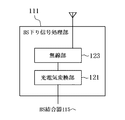
1本の光ファイバを上り回線及び下り回線で兼用するためには、例えば、図11のように、3dBカプラといった分岐カプラを光ファイバ伝送路に設けることが想定される。3dBカプラ407のポートP41は集中基地局(CS)401のCS下り信号処理部419に、ポートP42は集中基地局401のCS上り信号部417に、ポートP43は遠隔基地局(BS)403のBS下り信号処理部411に、ポートP44は遠隔基地局403のBS上り信号処理部413にそれぞれ接続される。   In order to use one optical fiber for both the uplink and the downlink, for example, it is assumed that a branch coupler such as a 3 dB coupler is provided in the optical fiber transmission line as shown in FIG. The port P41 of the 3 dB coupler 407 is in the CS downlink signal processing unit 419 of the centralized base station (CS) 401, the port P42 is in the CS upstream signal unit 417 of the centralized base station 401, and the port P43 is the BS of the remote base station (BS) 403. The port P44 is connected to the downlink signal processing unit 411 and the BS uplink signal processing unit 413 of the remote base station 403, respectively.

移動局410から集中基地局401への上り方向での信号伝送においては、BS上り信号処理部413は、移動局410から受信した信号(上り信号)をポートP44に入力する。そして、上り信号は、3dBカプラ407により2分割されて、ポートP41及びポートP42から出力される。つまり、CS上り信号処理部417は、信号強度が半減した上り信号を処理することになる。信号強度の半減は、SN比(Signal to Noise ratio)の低下を招き、CS上り信号処理部417での処理を困難にするおそれがある。集中基地局401から移動局410への下り方向での信号伝送においては、CS下り信号処理部419により生成された下り信号は、3dBカプラ407により2分割されて、ポートP43及びポートP44から出力される。つまり、BS下り信号処理部411は、CS上り信号処理部417と同様、信号強度が半減した下り信号を処理することになる。そして、BS下り信号処理部411は、信号強度が半減した下り信号を移動局410に送信する。   In uplink signal transmission from the mobile station 410 to the centralized base station 401, the BS uplink signal processing unit 413 inputs a signal (uplink signal) received from the mobile station 410 to the port P44. Then, the upstream signal is divided into two by the 3 dB coupler 407 and output from the port P41 and the port P42. That is, the CS uplink signal processing unit 417 processes an uplink signal whose signal intensity is halved. If the signal intensity is halved, the signal-to-noise ratio (SNR) is reduced, which may make it difficult for the CS upstream signal processing unit 417 to perform processing. In the signal transmission in the downlink direction from the centralized base station 401 to the mobile station 410, the downlink signal generated by the CS downlink signal processing unit 419 is divided into two by the 3 dB coupler 407 and output from the port P43 and the port P44. The That is, the BS downlink signal processing unit 411 processes the downlink signal whose signal strength is halved, like the CS uplink signal processing unit 417. BS downlink signal processing section 411 then transmits a downlink signal whose signal strength is halved to mobile station 410.

ここで、下り方向における信号強度の減少を防ぐためには、CoMP(Coordinated Multi-Point transmission/reception:セル間協調送受信)技術の利用が想定される。CoMPとは、ある移動局に対して複数のセル(遠隔基地局)が協調して送受信を行うことであり、所望信号電力を増大することができる。   Here, use of CoMP (Coordinated Multi-Point transmission / reception) technology is assumed to prevent a decrease in signal strength in the downlink direction. CoMP means that a plurality of cells (remote base stations) perform transmission / reception in cooperation with a certain mobile station, and the desired signal power can be increased.

図12のように、2つの遠隔基地局403a及び403bが協調して移動局と通信を行っているとする。3dBカプラ407のポートP41及びポートP42は、図11と同様、CS下り信号処理部419及びCS上り信号処理部417にそれぞれ接続されている。また、3dBカプラ407のポートP43及びポートP44は、遠隔基地局403a及び403bのWDM(Wavelength Division Multiplexing:波長分割多重方式)カプラ415a及び415bのポートP45a及びP45bにそれぞれ接続されている。WDMカプラ415aのポートP46a及びポートP47aは、BS下り信号処理部411a及びBS上り信号処理部413aにそれぞれ接続されている。また、WDMカプラ415bのポートP46b及びポートP47bは、BS下り信号処理部411b及びBS上り信号処理部413bにそれぞれ接続されている。なお、WDMカプラは、波長毎に信号を分波するものであり、ある一つの波長の信号を分割するものではない。そのため、分波に伴い信号強度が減少することはない。   As shown in FIG. 12, it is assumed that the two remote base stations 403a and 403b communicate with the mobile station in cooperation. Similarly to FIG. 11, the port P41 and the port P42 of the 3 dB coupler 407 are connected to the CS downlink signal processing unit 419 and the CS uplink signal processing unit 417, respectively. Further, the port P43 and the port P44 of the 3 dB coupler 407 are connected to the ports P45a and P45b of the WDM (Wavelength Division Multiplexing) couplers 415a and 415b of the remote base stations 403a and 403b, respectively. The port P46a and the port P47a of the WDM coupler 415a are connected to the BS downlink signal processing unit 411a and the BS uplink signal processing unit 413a, respectively. Further, the port P46b and the port P47b of the WDM coupler 415b are connected to the BS downlink signal processing unit 411b and the BS uplink signal processing unit 413b, respectively. The WDM coupler demultiplexes a signal for each wavelength, and does not divide a signal having a single wavelength. Therefore, the signal intensity does not decrease with demultiplexing.

下り方向において、CS下り信号処理部419からの下り信号は、3dBカプラ407により2分割されて、WDMカプラ415a及び415bを介して、BS下り信号処理部411a及び411bに伝送される。そして、BS下り信号処理部411a及び411bは、信号強度が半減した下り信号をそれぞれ移動局410に送信する。つまり、移動局410は、2つの遠隔基地局403a及び403bからの信号の合成信号を受信することになる。移動局410は、2つの遠隔基地局403a及び403bからの合成信号を処理することができるので、3dBカプラによる下り信号の信号強度の減少は解消される。   In the downlink direction, the downlink signal from the CS downlink signal processing unit 419 is divided into two by the 3 dB coupler 407 and transmitted to the BS downlink signal processing units 411a and 411b via the WDM couplers 415a and 415b. Then, BS downlink signal processing sections 411a and 411b transmit downlink signals whose signal strengths are halved to mobile station 410, respectively. That is, the mobile station 410 receives a composite signal of signals from the two remote base stations 403a and 403b. Since the mobile station 410 can process the combined signal from the two remote base stations 403a and 403b, the decrease in the signal strength of the downlink signal due to the 3 dB coupler is eliminated.

一方、上り方向においては、移動局410からの信号は、BS上り信号処理部413a及び413bにより受信される。そして、BS上り信号処理部413a及び413bが受信した信号は、3dBカプラ407によってそれぞれ分割されてCS上り信号処理部417に伝送される。つまり、CS上り信号処理部417には、BS上り信号処理部413a及び413bが受信した信号の合成信号ではなく、当該合成信号の半分のみが伝送される。   On the other hand, in the uplink direction, the signal from the mobile station 410 is received by the BS uplink signal processing units 413a and 413b. The signals received by the BS uplink signal processing sections 413a and 413b are divided by the 3 dB coupler 407 and transmitted to the CS uplink signal processing section 417. That is, only the half of the combined signal is transmitted to the CS upstream signal processing unit 417, not the combined signal of the signals received by the BS upstream signal processing units 413a and 413b.

従って、上記のような問題点に鑑みてなされた本発明の目的は、遠隔基地局からの上り信号の強度が減少することなく、当該信号が集中基地局に伝送される無線基地局を提供することにある。   Therefore, an object of the present invention made in view of the above problems is to provide a radio base station in which the signal is transmitted to the central base station without reducing the strength of the uplink signal from the remote base station. There is.

上述した諸課題を解決すべく、第1の観点による無線基地局は、
下り信号処理部及び上り信号処理部を有する集中基地局と、第1結合器及び第2結合器が設けられた光ファイバ伝送路を介して接続され、移動局と無線信号を送受信するN個の遠隔基地局(Nは2以上の自然数)とを備える無線基地局であって、
前記第1結合器は、N本のポートで構成される第1入出力ポート及び第2入出力ポートを有し、前記第1入出力ポートのいずれかのポートへの信号を、前記第2入出力ポートから分岐して出力し、前記第2入出力ポートのいずれかのポートへの信号を、前記第1入出力ポートから分岐して出力し、
前記第2結合器は、第1ポート、第2ポート及び第3ポートを有し、第1ポートへの信号を第2ポートから出力し、第3ポートへの信号を第1ポートから出力し、
N個の遠隔基地局は、前記第1入出力ポートにそれぞれ接続され、
前記第2入出力ポートのうち1つのポートは、前記第1ポートに接続され、
前記第2入出力ポートの残りのポート及び前記第2ポートは、前記上り信号処理部に接続されている無線基地局である。
In order to solve the above-described problems, the radio base station according to the first aspect is
N centralized base stations having a downlink signal processing unit and an uplink signal processing unit are connected via an optical fiber transmission line provided with a first coupler and a second coupler, and transmit and receive radio signals with a mobile station. A wireless base station including a remote base station (N is a natural number of 2 or more),
The first coupler has a first input / output port and a second input / output port composed of N ports, and a signal to any one of the first input / output ports is sent to the second input / output port. Branch from the output port and output, branch the signal to any of the second input / output ports from the first input / output port, and output
The second coupler has a first port, a second port, and a third port, outputs a signal to the first port from the second port, and outputs a signal to the third port from the first port;
N remote base stations are respectively connected to the first input / output ports;
One of the second input / output ports is connected to the first port;
The remaining ports of the second input / output port and the second port are radio base stations connected to the uplink signal processing unit.

また、前記第1結合器はNが2である3dBカプラであることが望ましい。   The first coupler is preferably a 3 dB coupler in which N is 2.

また、前記上り信号処理部は、前記第2入出力ポートの残りのポート及び前記第2ポートからの信号をそれぞれ電気信号に変換するN個の電気光変換部と、当該電気光変換部からのN個の電気信号を合成して増幅する1個の増幅部とを備えることが望ましい。   The upstream signal processing unit includes N electro-optical conversion units that convert the signals from the remaining ports of the second input / output port and the second port into electrical signals, and the electro-optical conversion unit. It is desirable to include one amplification unit that synthesizes and amplifies N electrical signals.

また、前記無線信号は、OFDM(Orthogonal Frequency-Division Multiplexing)通信方式又はCDMA(Code Division Multiple Access)通信方式における信号であることが望ましい。   The radio signal is preferably a signal in an OFDM (Orthogonal Frequency-Division Multiplexing) communication system or a CDMA (Code Division Multiple Access) communication system.

また、前記第3ポートは、前記下り信号処理部に接続されていることが望ましい。   The third port is preferably connected to the downlink signal processing unit.

また、前記第2結合器は、波長分割多重方式カプラであることが望ましい。   The second coupler is preferably a wavelength division multiplexing coupler.

また、前記第2結合器は、3端子サーキュレータであることが望ましい。   The second coupler is preferably a three-terminal circulator.

また、上述した諸課題を解決すべく、第2の観点による無線基地局は、
下り信号処理部及び上り信号処理部を有する集中基地局と、第1結合器及びN個の第2結合器が設けられた光ファイバ伝送路を介して接続され、移動局と無線信号を送受信するN個の遠隔基地局(Nは2以上の自然数)とを備える無線基地局であって、
前記第1結合器は、N本のポートで構成される出力ポート及び1本のポートで構成される入力ポートを有し、前記入力ポートへの信号を、前記出力ポートから分岐して出力し、
前記第2結合器は、第1ポート、第2ポート及び第3ポートを有し、第1ポートへの信号を第2ポートから出力し、第3ポートへの信号を第1ポートから出力し、
N個の遠隔基地局は、前記N個の第2結合器の第1ポートにそれぞれ接続され、
前記N個の第2結合器の第2ポートは、前記上り信号処理部にそれぞれ接続され、
前記N個の第2結合器の第3ポートは、前記出力ポートにそれぞれ接続され、
前記入力ポートは、前記下り信号処理部に接続されている無線基地局である。
In order to solve the above-mentioned problems, the radio base station according to the second aspect is
A centralized base station having a downlink signal processing unit and an uplink signal processing unit is connected via an optical fiber transmission line provided with a first coupler and N second couplers, and transmits and receives radio signals to and from a mobile station. A wireless base station comprising N remote base stations (N is a natural number of 2 or more),
The first coupler has an output port composed of N ports and an input port composed of one port, and a signal to the input port is branched from the output port and output.
The second coupler has a first port, a second port, and a third port, outputs a signal to the first port from the second port, and outputs a signal to the third port from the first port;
N remote base stations are respectively connected to the first ports of the N second couplers,
Second ports of the N second couplers are connected to the upstream signal processing unit, respectively.
A third port of each of the N second couplers is connected to the output port;
The input port is a radio base station connected to the downlink signal processing unit.

上記のように構成された本発明に係る無線基地局によれば、複数の遠隔基地局からの信号は第1結合器に入力し、分岐して出力される。分岐された1つの信号は、第2結合器を介して、分岐されることなく集中基地局の上り信号処理部に入力される。また、分岐された残りの信号は、集中基地局の上り信号処理部に直接入力される。よって、複数の遠隔基地局からの信号は全て上り信号処理部に伝送される。つまり、複数の遠隔基地局からの信号の強度は、減少することがない。よって、遠隔基地局からの信号のSN比の劣化が抑えられ、通信システムにおいて安定した通信が実現できる。   According to the radio base station of the present invention configured as described above, signals from a plurality of remote base stations are input to the first coupler, branched and output. One branched signal is input to the uplink signal processing unit of the centralized base station via the second coupler without being branched. Further, the remaining branched signal is directly input to the uplink signal processing unit of the centralized base station. Therefore, all signals from a plurality of remote base stations are transmitted to the uplink signal processing unit. That is, the strength of signals from a plurality of remote base stations does not decrease. Therefore, the degradation of the signal-to-noise ratio of the signal from the remote base station is suppressed, and stable communication can be realized in the communication system.

図1は、本発明の第1実施形態に係る光張り出し無線基地局を含む通信システムの概略的な構成図である。FIG. 1 is a schematic configuration diagram of a communication system including an optical extension radio base station according to the first embodiment of the present invention. 図2は、本発明の第1実施形態に係る光張り出し無線基地局の概略構成を示す機能ブロック図である。FIG. 2 is a functional block diagram showing a schematic configuration of the optical extension radio base station according to the first embodiment of the present invention. 図3は、本発明の第1実施形態に係るBS下り信号処理部の概略構成を示す機能ブロック図である。FIG. 3 is a functional block diagram showing a schematic configuration of the BS downlink signal processing unit according to the first embodiment of the present invention. 図4は、本発明の第1実施形態に係るBS上り信号処理部の概略構成を示す機能ブロック図である。FIG. 4 is a functional block diagram showing a schematic configuration of the BS uplink signal processing unit according to the first embodiment of the present invention. 図5は、本発明の第1実施形態に係るCS上り信号処理部の概略構成を示す機能ブロック図である。FIG. 5 is a functional block diagram showing a schematic configuration of the CS uplink signal processing unit according to the first embodiment of the present invention. 図6は、本発明の第1実施形態に係るCS下り信号処理部の概略構成を示す機能ブロック図である。FIG. 6 is a functional block diagram showing a schematic configuration of the CS downlink signal processing unit according to the first embodiment of the present invention. 図7は、本発明の第1実施形態に係るBS上り信号処理部の概略構成を示す機能ブロック図である。FIG. 7 is a functional block diagram showing a schematic configuration of the BS uplink signal processing unit according to the first embodiment of the present invention. 図8は、本発明の第1実施形態に係るBS下り信号処理部の概略構成を示す機能ブロック図である。FIG. 8 is a functional block diagram showing a schematic configuration of the BS downlink signal processing unit according to the first embodiment of the present invention. 図9は、本発明の第2実施形態に係る光張り出し無線基地局を含む通信システムの概略的な構成図である。FIG. 9 is a schematic configuration diagram of a communication system including an optical extension radio base station according to the second embodiment of the present invention. 図10は、本発明の第2実施形態に係る光張り出し無線基地局の概略構成を示す機能ブロック図である。FIG. 10 is a functional block diagram showing a schematic configuration of an optical extension radio base station according to the second embodiment of the present invention. 図11は、光張り出し無線基地局の概略構成の一例を示す機能ブロック図である。FIG. 11 is a functional block diagram illustrating an example of a schematic configuration of the light extension radio base station. 図12は、光張り出し無線基地局の概略構成の一例を示す機能ブロック図である。FIG. 12 is a functional block diagram illustrating an example of a schematic configuration of the light extension radio base station.

以下、本発明に係る実施形態について、図面を参照して説明する。   Hereinafter, embodiments according to the present invention will be described with reference to the drawings.

(第1実施形態)
図1は、本発明の第1実施形態に係る光張り出し無線基地局を含む通信システムの概略的な構成図である。通信システム10は、光張り出し無線基地局(無線基地局)100と移動局110とを有するものである。通信システム10は、例えば、OFDM(Orthogonal Frequency-Division Multiplexing:直交周波数分割多重方式)通信方式やCDMA(Code Division Multiple Access:符号分割多元接続)通信方式が採用されたシステムである。光張り出し無線基地局100は、集中基地局101と、当該集中基地局101と光ファイバ伝送路105を介して接続されているN個の遠隔基地局103(103a及び103b)とを備える。Nは2以上の自然数である。なお、本実施形態では、Nは2であるとして説明する。移動局110は、光張り出し無線基地局100と無線通信を行うもので、携帯電話機などの無線通信端末である。
(First embodiment)
FIG. 1 is a schematic configuration diagram of a communication system including an optical extension radio base station according to the first embodiment of the present invention. The communication system 10 includes a light projecting radio base station (radio base station) 100 and a mobile station 110. The communication system 10 is a system that employs, for example, an OFDM (Orthogonal Frequency-Division Multiplexing) communication method or a CDMA (Code Division Multiple Access) communication method. The optical extension radio base station 100 includes a centralized base station 101 and N remote base stations 103 (103a and 103b) connected to the centralized base station 101 via an optical fiber transmission path 105. N is a natural number of 2 or more. In the present embodiment, it is assumed that N is 2. The mobile station 110 performs wireless communication with the light protruding radio base station 100 and is a wireless communication terminal such as a mobile phone.

集中基地局101は、デジタル信号処理機能、保守監視機能などを備え、遠隔基地局103のセル間の無線リソース制御を一括して行なう。遠隔基地局103は、移動局110とRF(Radio Frequency)信号(無線信号)を送受信する機能や信号の変復調機能などが備えられている。通信システム10にOFDM通信方式又はCDMA通信方式が採用されている場合、当該RF信号はOFDM通信方式又はCDMA通信方式の信号である。図1において、領域104aは、基地局103aのセル(通信可能エリア)を示している。領域104bは、基地局103bのセルを示している。移動局110が図1のように2つの領域が重なる領域に位置する場合、移動局110は、遠隔基地局103a及び103bの双方と通信することができる。よって、光張り出し無線基地局100は、CoMPによって移動局110と通信することができる。   The centralized base station 101 has a digital signal processing function, a maintenance monitoring function, and the like, and performs radio resource control between cells of the remote base station 103 at once. The remote base station 103 has a function of transmitting / receiving an RF (Radio Frequency) signal (radio signal) to / from the mobile station 110, a signal modulation / demodulation function, and the like. When the OFDM communication system or CDMA communication system is employed in the communication system 10, the RF signal is a signal of the OFDM communication system or CDMA communication system. In FIG. 1, an area 104a indicates a cell (communication area) of the base station 103a. An area 104b shows a cell of the base station 103b. When the mobile station 110 is located in an area where the two areas overlap as shown in FIG. 1, the mobile station 110 can communicate with both the remote base stations 103a and 103b. Therefore, the light extension radio base station 100 can communicate with the mobile station 110 by CoMP.

光ファイバ伝送路105には、複数の光ファイバの経路を結合する第1結合器107及び第2結合器109が設けられている。   The optical fiber transmission line 105 is provided with a first coupler 107 and a second coupler 109 that couple paths of a plurality of optical fibers.

第1結合器107は、N本のポートで構成される第1入出力ポート及びN本のポートで構成される第2入出力ポートを有している。本実施形態ではNは2であり、第1入出力ポートは、ポートP1及びP2で構成される。また、第2入出力ポートは、ポートP3及びP4で構成される。第1結合器107は、第1入出力ポートのいずれかのポートへの信号を、第2入出力ポートの全てのポートから分岐して出力し、また第2入出力ポートのいずれかのポートへの信号を、第1入出力ポートから分岐して出力する。第1結合器107は、例えば光分岐器である。光分岐器は、例えば、光ファイバの融着延伸により生成される分岐カプラである。   The first coupler 107 has a first input / output port composed of N ports and a second input / output port composed of N ports. In this embodiment, N is 2, and the first input / output port is composed of ports P1 and P2. The second input / output port includes ports P3 and P4. The first coupler 107 divides and outputs a signal to any one of the first input / output ports from all the ports of the second input / output port, and also outputs to any one of the second input / output ports. The signal is branched from the first input / output port and output. The first coupler 107 is, for example, an optical branching device. The optical branching device is, for example, a branching coupler generated by fusion drawing of an optical fiber.

第2結合器109は、第1ポートP5(以下、ポートP5と称す)、第2ポートP6(以下、ポートP6と称す)及び第3ポートP7(以下、ポートP7と称す)を有し、ポートP5への信号をポートP6から出力し、ポートP7への信号をポートP5から出力する。第2結合器109は、例えば3端子サーキュレータや波長ごとに光の経路を決定できる光合分波器である。光合分波器は、例えば、融着延伸により生成されるWDMカプラである。   The second coupler 109 has a first port P5 (hereinafter referred to as port P5), a second port P6 (hereinafter referred to as port P6) and a third port P7 (hereinafter referred to as port P7). A signal to P5 is output from port P6, and a signal to port P7 is output from port P5. The second coupler 109 is, for example, a three-terminal circulator or an optical multiplexer / demultiplexer that can determine the light path for each wavelength. The optical multiplexer / demultiplexer is, for example, a WDM coupler generated by fusion drawing.

図2は、本発明の第1実施形態に係る光張り出し無線基地局の概略構成を示す機能ブロック図である。   FIG. 2 is a functional block diagram showing a schematic configuration of the optical extension radio base station according to the first embodiment of the present invention.

遠隔基地局103は、BS下り信号処理部111と、BS上り信号処理部113と、BS結合器115とを備えている。なお、図2に示された遠隔基地局103に関する機能ブロックは、遠隔基地局103a及び103bにおいて共通であり、遠隔基地局103aに関する機能ブロックの参照符号にはaを、遠隔基地局103bに関する機能ブロックの参照符号にはbを付して説明する。また、下り信号とは、集中基地局101から遠隔基地局103を介して移動局110へ伝送される信号であり、上り信号とは、移動局110から遠隔基地局103を介して集中基地局101へ伝送される信号である。   The remote base station 103 includes a BS downlink signal processing unit 111, a BS uplink signal processing unit 113, and a BS coupler 115. The functional blocks related to the remote base station 103 shown in FIG. 2 are common to the remote base stations 103a and 103b. The reference numeral of the functional block related to the remote base station 103a is a, and the functional block related to the remote base station 103b. In the following description, b is attached to the reference numeral. The downlink signal is a signal transmitted from the centralized base station 101 to the mobile station 110 via the remote base station 103, and the upstream signal is the centralized base station 101 from the mobile station 110 via the remote base station 103. It is a signal transmitted to.

BS下り信号処理部111は、集中基地局101からの下り信号を、光ファイバ伝送路105を介して受信し、移動局110に向け送信するもので、例えば図3のように構成することができる。光電気変換部121は、集中基地局101からの光信号を電気信号に変換するもので、例えばフォトダイオードである。無線部123は、電気信号をアップコンバートしてRF信号を生成し、アンテナを介して移動局110に向けRF信号を送信するものである。電気信号のアップコンバートは、例えば、無線部123の局部発振器と混合器(ミキサ)とにより実現される。   The BS downlink signal processing unit 111 receives a downlink signal from the centralized base station 101 via the optical fiber transmission line 105 and transmits it to the mobile station 110, and can be configured as shown in FIG. 3, for example. . The photoelectric conversion unit 121 converts an optical signal from the central base station 101 into an electrical signal, and is, for example, a photodiode. The radio unit 123 generates an RF signal by up-converting the electrical signal, and transmits the RF signal to the mobile station 110 via the antenna. The up-conversion of the electric signal is realized by, for example, a local oscillator of the radio unit 123 and a mixer (mixer).

BS上り信号処理部113は、移動局110からの上り信号を受信して、光ファイバ伝送路105を介して集中基地局101に送信するものである。   The BS uplink signal processing unit 113 receives an uplink signal from the mobile station 110 and transmits it to the centralized base station 101 via the optical fiber transmission path 105.

BS上り信号処理部113は、例えば図4のように構成することができる。無線部125は、アンテナを介して移動局110からのRF信号を受信し、ダウンコンバートしてIF(Intermediate Frequency:中間周波数)信号を生成するものである。RF信号のダウンコンバートは、例えば、無線部125の局部発振器と混合器とにより実現される。電気光変換部127は、IF信号を光信号に変換するもので、例えばレーザダイオードである。なお、無線部125は、無線部123と完全に独立している必要はなく、例えば構成要素であるアンテナやフィルタなどを共用してもよい。以下、本実施形態では、BS上り信号処理部113から出力される信号は、波長がλuの光信号であるとする。   The BS uplink signal processing unit 113 can be configured as shown in FIG. 4, for example. The radio unit 125 receives an RF signal from the mobile station 110 via an antenna and down-converts it to generate an IF (Intermediate Frequency) signal. The down conversion of the RF signal is realized by, for example, a local oscillator of the radio unit 125 and a mixer. The electro-optical conversion unit 127 converts the IF signal into an optical signal, and is, for example, a laser diode. Note that the wireless unit 125 does not need to be completely independent of the wireless unit 123, and may share, for example, an antenna or a filter that is a component. Hereinafter, in the present embodiment, it is assumed that the signal output from the BS uplink signal processing unit 113 is an optical signal having a wavelength of λu.

BS結合器115は、BS上り信号処理部113からの上り信号を集中基地局101(第1結合器107)へ、集中基地局101(第1結合器107)からの信号をBS下り信号処理部111へ伝送するもので、例えばWDMカプラや3端子サーキュレータである。BS結合器115a及び115bは、第1結合器107のポートP1及びポートP2にそれぞれ接続されている。   The BS coupler 115 receives the uplink signal from the BS uplink signal processing unit 113 to the centralized base station 101 (first coupler 107) and the signal from the centralized base station 101 (first coupler 107) to the BS downstream signal processing unit. For example, a WDM coupler or a three-terminal circulator. BS couplers 115a and 115b are connected to port P1 and port P2 of first coupler 107, respectively.

BS上り信号処理部113aからの光信号は、第1結合器107のポートP1に入力し、分岐して、ポートP3及びP4から出力される。第1結合器107は3dBカプラである場合、ポートP3及びP4からの出力信号の信号強度は、ポートP1への入力信号の信号強度の半分となる。同様に、BS上り信号処理部113bからの光信号は、第1結合器107のポートP2に入力し、ポートP3及びP4から分岐して出力される。   The optical signal from the BS upstream signal processing unit 113a is input to the port P1 of the first coupler 107, branches, and is output from the ports P3 and P4. When the first coupler 107 is a 3 dB coupler, the signal strength of the output signals from the ports P3 and P4 is half of the signal strength of the input signal to the port P1. Similarly, the optical signal from the BS upstream signal processing unit 113b is input to the port P2 of the first coupler 107, branched from the ports P3 and P4, and output.

ポートP4は、第2結合器109のポートP5に接続されている。第2入出力ポートの残りのポート、つまりポートP3は、集中基地局101の後述するCS上り信号処理部117に接続されている。よって、ポートP3からの出力信号は、CS上り信号処理部117に入力され、ポートP4からの出力信号は、第2結合器109のポートP5に入力される。   The port P4 is connected to the port P5 of the second coupler 109. The remaining ports of the second input / output port, that is, the port P3 are connected to a CS uplink signal processing unit 117 described later of the centralized base station 101. Therefore, the output signal from the port P3 is input to the CS uplink signal processing unit 117, and the output signal from the port P4 is input to the port P5 of the second coupler 109.

第2結合器109のポートP6は、集中基地局101のCS上り信号処理部117に結合されている。そして、ポートP7を、集中基地局101の後述するCS下り信号処理部119に接続することができる。第2結合器109のポートP5への入力信号は、分岐することなくポートP6から出力され、CS上り信号処理部117に入力される。また、第2結合器109のポートP7への入力信号は、分岐することなくポートP5から出力される。   Port P 6 of second coupler 109 is coupled to CS uplink signal processing section 117 of centralized base station 101. Then, the port P7 can be connected to a CS downlink signal processing unit 119 described later of the centralized base station 101. An input signal to the port P5 of the second coupler 109 is output from the port P6 without branching and input to the CS uplink signal processing unit 117. An input signal to the port P7 of the second coupler 109 is output from the port P5 without branching.

続いて、遠隔基地局103の機能ブロックについて説明する。遠隔基地局103は、CS上り信号処理部117(請求項における上り信号処理部)と、CS下り信号処理部119(請求項における下り信号処理部)とを備えている。   Next, functional blocks of the remote base station 103 will be described. The remote base station 103 includes a CS uplink signal processing unit 117 (uplink signal processing unit in the claims) and a CS downlink signal processing unit 119 (downlink signal processing unit in the claims).

CS上り信号処理部117は、遠隔基地局103からの上り信号を受信して、復調するもので、例えば図5のように構成することができる。光電気変換部131(131−1及び131−2)は、遠隔基地局103からの光信号を電気信号(出力電流)に変換するもので、例えばフォトダイオードである。増幅部133は、複数の光電気変換部131−1及び131−2からの出力電流を合成する。そして、増幅部133は、合成された出力電流を電圧に変換して増幅するものである。増幅部133は、例えば、電流・電圧変換器と帰還増幅回路とである。2つのフォトダイオードは、帰還増幅回路の2つの入力端子間に並列に接続されることになる。第1結合器107のポートP3及び第2結合器109のポートP6の双方からの信号を1つの増幅部133により一括して増幅することにより、増幅部133を複数設ける必要はなく、部品数の削減が可能となる。また、部品数の削減に伴いCS上り信号処理部117の回路規模を小さくすることができる。ベースバンド部135は、増幅された電圧信号をAD変換及び高速フーリエ変換(FFT:Fast Fourier Transform)して、信号を復調するものである。   The CS uplink signal processing unit 117 receives an uplink signal from the remote base station 103 and demodulates it, and can be configured as shown in FIG. 5, for example. The photoelectric conversion unit 131 (131-1 and 131-2) converts an optical signal from the remote base station 103 into an electrical signal (output current), and is, for example, a photodiode. The amplifying unit 133 combines output currents from the plurality of photoelectric conversion units 131-1 and 131-2. The amplifying unit 133 converts the synthesized output current into a voltage and amplifies it. The amplification unit 133 is, for example, a current / voltage converter and a feedback amplification circuit. The two photodiodes are connected in parallel between the two input terminals of the feedback amplifier circuit. By amplifying the signals from both the port P3 of the first coupler 107 and the port P6 of the second coupler 109 by a single amplifying unit 133, it is not necessary to provide a plurality of amplifying units 133. Reduction is possible. Further, the circuit scale of the CS upstream signal processing unit 117 can be reduced with the reduction in the number of components. The baseband unit 135 demodulates the amplified voltage signal by AD conversion and fast Fourier transform (FFT).

CS下り信号処理部119は、移動局110に送るべき下り信号を変調し、遠隔基地局103に向け送信するものである。CS下り信号処理部119は、例えば図6のように構成することができる。ベースバンド部137は、ベースバンド信号をデジタル変調し、DA変換するものである。電気光変換部139は、DA変換された信号を光信号に変換するものであり、例えばレーザダイオードである。なお、ベースバンド部137は、ベースバンド部135と完全に独立している必要はなく、例えば高速フーリエ変換やデジタル変調などソフトウェア処理を行うCPU(中央処理装置)を共用してもよい。以下、本実施形態では、CS下り信号処理部119から出力される信号は、波長がλdの光信号であるとする。   The CS downlink signal processing unit 119 modulates a downlink signal to be sent to the mobile station 110 and transmits it to the remote base station 103. The CS downlink signal processing unit 119 can be configured as shown in FIG. 6, for example. The baseband unit 137 digitally modulates a baseband signal and performs DA conversion. The electro-optical converter 139 converts the DA-converted signal into an optical signal, and is a laser diode, for example. Note that the baseband unit 137 does not need to be completely independent of the baseband unit 135, and may share a CPU (central processing unit) that performs software processing such as fast Fourier transform and digital modulation. Hereinafter, in the present embodiment, it is assumed that the signal output from the CS downlink signal processing unit 119 is an optical signal having a wavelength of λd.

CS下り信号処理部119からの信号は、第2結合器109のポートP7に入力され、分岐することなくポートP5から出力される。第2結合器109がWDMカプラの場合、信号が出力されるポートは、入力された信号の波長により決定される。よって、CS下り信号処理部119からの信号がポートP6に出力されないようにするために、CS下り信号処理部119からの信号の波長λdは、BS上り信号処理部113から出力される信号の波長λuと異なる必要がある。また、第2結合器109が3端子サーキュレータの場合、入力ポートと出力ポートの経路は3端子サーキュレータの構造により予め決まっているため、出力先は波長に依存するものではない。よって、λdをλuと同じ値にすることもできる。   The signal from the CS downlink signal processing unit 119 is input to the port P7 of the second coupler 109, and is output from the port P5 without branching. When the second coupler 109 is a WDM coupler, the port from which the signal is output is determined by the wavelength of the input signal. Therefore, in order to prevent the signal from the CS downlink signal processing unit 119 from being output to the port P6, the wavelength λd of the signal from the CS downlink signal processing unit 119 is the wavelength of the signal output from the BS uplink signal processing unit 113. Must be different from λu. When the second coupler 109 is a three-terminal circulator, the path between the input port and the output port is determined in advance by the structure of the three-terminal circulator, so that the output destination does not depend on the wavelength. Therefore, λd can be set to the same value as λu.

ポートP5から出力された下り信号は、第1結合器107のポートP4に入力され、ポートP1及びP2から分岐して出力される。そして、ポートP1及びP2から出力された下り信号は、BS結合器115a及び115bを介して、BS下り信号処理部111a及び111bに入力され、移動局110に送信される。   The downlink signal output from the port P5 is input to the port P4 of the first coupler 107, branched from the ports P1 and P2, and output. The downlink signals output from the ports P1 and P2 are input to the BS downlink signal processing units 111a and 111b via the BS couplers 115a and 115b and transmitted to the mobile station 110.

上記説明では、遠隔基地局103は、1本のアンテナにより移動局110と通信する場合について説明したが、上述した集中基地局101と遠隔基地局103との接続態様は、遠隔基地局103が複数アンテナを有する場合も同様である。遠隔基地局103が複数アンテナを有する場合、光張り出し無線基地局100は、複数アンテナを有する移動局110とMIMO(Multiple Input Multiple Output)通信することができる。以下、遠隔基地局103が、2本のアンテナを有する場合について説明する。   In the above description, the remote base station 103 communicates with the mobile station 110 using one antenna. However, the above-described connection mode between the central base station 101 and the remote base station 103 includes a plurality of remote base stations 103. The same applies to the case with an antenna. When the remote base station 103 has a plurality of antennas, the light-extending radio base station 100 can perform MIMO (Multiple Input Multiple Output) communication with the mobile station 110 having a plurality of antennas. Hereinafter, a case where the remote base station 103 has two antennas will be described.

まず、MIMO通信における上り方向での信号伝送について説明する。MIMO通信が可能なBS上り信号処理部113は、図7のように、無線部125−1及び125−2と、加算部126と、電気光変換部127とを備える。無線部125−1及び125−2は、上述の無線部125の機能に加え、移動局110からのRF信号をダウンコンバートする際、アンテナ毎に異なる周波数帯域のIF信号を生成する。異なる周波数帯域のIF信号の生成は、ダウンコンバートする際に使用される局部発振器の信号の周波数を異ならせることにより実現される。異なる周波数帯域のIF信号とは、各信号の周波数帯域が互いに重なり合わないことを意味する。   First, signal transmission in the uplink direction in MIMO communication will be described. The BS uplink signal processing unit 113 capable of MIMO communication includes radio units 125-1 and 125-2, an addition unit 126, and an electro-optical conversion unit 127 as shown in FIG. In addition to the functions of the wireless unit 125 described above, the wireless units 125-1 and 125-2 generate IF signals of different frequency bands for each antenna when down-converting the RF signal from the mobile station 110. Generation of IF signals in different frequency bands is realized by changing the frequency of the signal of the local oscillator used for down-conversion. IF signals in different frequency bands mean that the frequency bands of the signals do not overlap each other.

加算部126は、無線部125−1及び125−2により生成されたIF信号を周波数領域で多重化する。無線部125−1及び125−2のIF信号は、周波数領域において互いに重なり合わないため、複数のIF信号を多重化してもFFTによって分離して抽出することが可能となる。多重化された信号は、電気光変換部127により、一つの波長の光信号に変換される。BS上り信号処理部113からの光信号は、第1結合器107及び第2結合器109を介して、CS上り信号処理部117に入力される。   Adder 126 multiplexes the IF signals generated by radio units 125-1 and 125-2 in the frequency domain. Since the IF signals of the radio units 125-1 and 125-2 do not overlap each other in the frequency domain, even if a plurality of IF signals are multiplexed, they can be separated and extracted by FFT. The multiplexed signal is converted into an optical signal of one wavelength by the electro-optical converter 127. The optical signal from the BS upstream signal processing unit 113 is input to the CS upstream signal processing unit 117 via the first coupler 107 and the second coupler 109.

MIMO通信が可能なCS上り信号処理部117の機能ブロック図は、図5と同様であり、光電気変換部131−1及び131−2と、増幅部133と、ベースバンド部135とである。光電気変換部131及び増幅部133の機能は、1本のアンテナによる通信と同様であるため、説明は省略する。   The functional block diagram of the CS uplink signal processing unit 117 capable of MIMO communication is the same as that in FIG. 5, and is the photoelectric conversion units 131-1 and 131-2, the amplification unit 133, and the baseband unit 135. Since the functions of the photoelectric conversion unit 131 and the amplification unit 133 are the same as the communication using one antenna, the description thereof is omitted.

ベースバンド部135は、まず、増幅部133により増幅された電気信号をAD変換する。続いて、ベースバンド部135は、AD変換された信号に対して高速フーリエ変換を行い、遠隔基地局103a及び103bのアンテナ毎に対応させて周波数分離して、復調する。遠隔基地局103a及び103bのアンテナ毎に異なる周波数帯域のIF信号が生成されるため、ベースバンド部135は、高速フーリエ変換によりアンテナ毎の信号に分離することができる。よって、光張り出し無線基地局100は、移動局110とMIMO通信を行なうことができる。高速フーリエ変換による周波数分離は、アナログフィルタ等での周波数分離に比べ精度が良い。そのため、アナログフィルタ等での周波数分離に比べ、アンテナ毎に生成される複数のIF信号同士の周波数間隔を狭めることが可能である。よって、IF信号における周波数リソースを有効利用できる。なお、本発明は、IF信号の周波数分離を高速フーリエ変換により行なうことに限定されるものではなく、例えば、バンドパスフィルタなどのアナログフィルタによりIF信号の周波数分離を行なうこともできる。この場合、ベースバンド部135によるAD変換は不要となる。   The baseband unit 135 first AD converts the electrical signal amplified by the amplification unit 133. Subsequently, the baseband unit 135 performs fast Fourier transform on the AD-converted signal, separates the frequency corresponding to each antenna of the remote base stations 103a and 103b, and demodulates. Since an IF signal of a different frequency band is generated for each antenna of the remote base stations 103a and 103b, the baseband unit 135 can be separated into signals for each antenna by fast Fourier transform. Therefore, the optical extension radio base station 100 can perform MIMO communication with the mobile station 110. The frequency separation by the fast Fourier transform is more accurate than the frequency separation by an analog filter or the like. Therefore, compared with frequency separation using an analog filter or the like, it is possible to narrow the frequency interval between a plurality of IF signals generated for each antenna. Therefore, the frequency resource in the IF signal can be effectively used. The present invention is not limited to performing frequency separation of IF signals by fast Fourier transform. For example, frequency separation of IF signals can be performed by an analog filter such as a bandpass filter. In this case, AD conversion by the baseband unit 135 is not necessary.

続いて、MIMO通信における下り方向での信号伝送について説明する。MIMO通信が可能なCS下り信号処理部119の機能ブロック図は、図6と同様であり、ベースバンド部137と、電気光変換部139とである。電気光変換部139の機能は、一本のアンテナによる通信と同様であるため、説明は省略する。   Next, downlink signal transmission in MIMO communication will be described. A functional block diagram of the CS downlink signal processing unit 119 capable of MIMO communication is the same as that in FIG. 6, and is a baseband unit 137 and an electro-optical conversion unit 139. Since the function of the electro-optical conversion unit 139 is the same as that of communication using one antenna, the description thereof is omitted.

ベースバンド部137は、複数の遠隔基地局103a及び103bへの伝送信号を、各遠隔基地局のアンテナ毎に周波数帯域が互いに重なり合わないように生成する。そして、ベースバンド部137は、生成された伝送信号を多重化し、DA変換する。DA変換された信号は、電気光変換部139により、光信号に変換され、第2結合器109及び第1結合器107を介して、BS下り信号処理部111に入力される。   The baseband unit 137 generates transmission signals to the plurality of remote base stations 103a and 103b so that the frequency bands do not overlap each other for each antenna of each remote base station. Then, the baseband unit 137 multiplexes the generated transmission signal and performs DA conversion. The DA-converted signal is converted into an optical signal by the electro-optical conversion unit 139 and input to the BS downlink signal processing unit 111 via the second coupler 109 and the first coupler 107.

MIMO通信が可能なBS下り信号処理部111は、図8のように、光電気変換部121と、信号処理部122と、無線部123−1及び123−2とを備える。光電気変換部121の機能は、一本のアンテナによる通信と同様であるため、説明は省略する。   As shown in FIG. 8, the BS downlink signal processing unit 111 capable of MIMO communication includes a photoelectric conversion unit 121, a signal processing unit 122, and radio units 123-1 and 123-2. Since the function of the photoelectric conversion unit 121 is the same as that of communication using one antenna, the description thereof is omitted.

信号処理部122は、光電気変換部121からの電気信号をAD変換する。続いて、信号処理部122は、AD変換された信号に対して高速フーリエ変換を行ない、アンテナ毎に対応させて周波数分離する。遠隔基地局103のアンテナ毎に関して伝送信号の周波数帯域は重なり合っていないため、信号処理部122は、遠隔基地局103のアンテナ毎に対応する信号を抽出することができる。   The signal processing unit 122 AD converts the electrical signal from the photoelectric conversion unit 121. Subsequently, the signal processing unit 122 performs fast Fourier transform on the AD-converted signal, and performs frequency separation corresponding to each antenna. Since the transmission signal frequency bands do not overlap for each antenna of the remote base station 103, the signal processing unit 122 can extract a signal corresponding to each antenna of the remote base station 103.

続いて、信号処理部122は、アンテナ毎に抽出した信号それぞれに対してIFFT(Inverse Fast Fourier Transform:逆高速フーリエ変換)を行い、DA変換する。   Subsequently, the signal processing unit 122 performs IFFT (Inverse Fast Fourier Transform) on each of the signals extracted for each antenna, and performs DA conversion.

なお、本発明は、信号の周波数分離を高速フーリエ変換により行なうことに限定されるものではなく、例えば、バンドパスフィルタなどのアナログフィルタにより周波数分離を行なうこともできる。この場合、信号処理部122によるAD変換、逆高速フーリエ変換及びDA変換は不要となる。   The present invention is not limited to performing frequency separation of signals by fast Fourier transform. For example, frequency separation can be performed by an analog filter such as a bandpass filter. In this case, AD conversion, inverse fast Fourier transform, and DA conversion by the signal processing unit 122 are unnecessary.

無線部123−1及び123−2は、信号処理部122により各無線部に振り分けられた信号を、アップコンバートする。そして、無線部123−1及び123−2は、アップコンバートされた信号を増幅し、各アンテナを介して移動局110に送信する。   The radio units 123-1 and 123-2 up-convert signals distributed to the radio units by the signal processing unit 122. Then, the radio units 123-1 and 123-2 amplify the upconverted signal and transmit the amplified signal to the mobile station 110 via each antenna.

このように本実施形態では、上り信号を受信するBS上り信号処理部113a及び113bは、信号を分岐する第1結合器107のポートP1又はP2に接続されている。第1結合器107のポートP3はCS上り信号処理部117に接続され、第1結合器107のポートP4は、第2結合器109のポートP5及びP6を経て、CS上り信号処理部117に接続されている。よって、第1結合器107により分岐された上り信号は、CS上り信号処理部117に全て集まることになる。つまり、CS上り信号処理部117が集結した信号を合成することにより、信号強度の減少なく上り信号が遠隔基地局103a及び103bから集中基地局101に伝送されることになる。よって、上り信号のSN比の劣化が抑えられ、通信システム10において安定した通信が実現できる。   As described above, in the present embodiment, the BS uplink signal processing units 113a and 113b that receive the uplink signal are connected to the port P1 or P2 of the first coupler 107 that branches the signal. The port P3 of the first coupler 107 is connected to the CS upstream signal processing unit 117, and the port P4 of the first coupler 107 is connected to the CS upstream signal processing unit 117 via the ports P5 and P6 of the second coupler 109. Has been. Therefore, all the upstream signals branched by the first coupler 107 are collected in the CS upstream signal processing unit 117. That is, by combining the signals collected by the CS uplink signal processing unit 117, the uplink signals are transmitted from the remote base stations 103a and 103b to the centralized base station 101 without reducing the signal strength. Therefore, deterioration of the S / N ratio of the uplink signal is suppressed, and stable communication can be realized in the communication system 10.

また、本実施形態では、CS上り信号処理部117は、2個の光電気変換部131−1及び131−2と、1個の増幅部133とを備えることができる。つまり、2個の光電気変換部131−1及び131−2からの電気信号を別々に増幅せずに、1個の増幅部133で、電気信号を合成して一括して増幅する。よって、増幅部133を複数設ける必要はなく、部品数の削減が可能となる。また、部品数の削減に伴いCS上り信号処理部117の回路規模を小さくすることができる。   In this embodiment, the CS uplink signal processing unit 117 can include two photoelectric conversion units 131-1 and 131-2 and one amplification unit 133. That is, the electric signals from the two photoelectric conversion units 131-1 and 131-2 are not separately amplified, but the single amplification unit 133 synthesizes the electric signals and amplifies them in a lump. Therefore, it is not necessary to provide a plurality of amplifiers 133, and the number of parts can be reduced. Further, the circuit scale of the CS upstream signal processing unit 117 can be reduced with the reduction in the number of components.

また、本実施形態では、移動局110と遠隔基地局103とが送受信する無線信号は、OFDM通信方式又はCDMA通信方式における信号とすることができる。遠隔基地局103a及び103bは、移動局110から希望波のみならず、当該所望波の遅延波も併せて受信することがある。遅延波も含む上り信号は、集中基地局101のCS上り信号処理部117で合成されることになり、遅延波が多いほどCS上り信号処理部117での復調処理に悪影響を及ぼすことになる。しかし、通信システム10にOFDM通信方式が採用される場合、無線信号にはガードインターバルが付加される。ガードインターバルにより、CS上り信号処理部117で遅延波が合成されたとしても、復調の精度を上げることができる。また、通信システム10にCDMA通信方式が採用される場合は、レイク受信技術の使用により、CS上り信号処理部117は拡散符号を用いた逆拡散処理で複数の遅延波を合成して希望波の劣化を防ぐことができる。   In this embodiment, the radio signal transmitted and received between the mobile station 110 and the remote base station 103 can be a signal in the OFDM communication system or the CDMA communication system. The remote base stations 103a and 103b may receive not only the desired wave from the mobile station 110 but also the delayed wave of the desired wave. The uplink signal including the delayed wave is synthesized by the CS uplink signal processing unit 117 of the centralized base station 101. The more the delayed wave, the worse the demodulation process in the CS uplink signal processing unit 117. However, when the OFDM communication system is adopted in the communication system 10, a guard interval is added to the radio signal. Even if a delayed wave is synthesized by the CS uplink signal processing unit 117 by the guard interval, the accuracy of demodulation can be improved. When the CDMA communication system is adopted in the communication system 10, the CS uplink signal processing unit 117 combines a plurality of delayed waves by despreading processing using a spreading code by using the rake reception technique. Deterioration can be prevented.

また、本実施形態では、第2結合器109のポートP7は、CS下り信号処理部119に接続されている。これにより、CS下り信号処理部119からの下り信号は、第2結合器109のポートP7及びP5並びに第1結合器107のポートP4を経て、ポートP1及びP2から出力される。そして、下り信号は、BS結合器115a及び115bを経て遠隔基地局103aのBS下り信号処理部111a及び111bに伝送される。よって、ポートP7がCS下り信号処理部119に接続されることにより、ポートP5とポートP4との間、ポートP1とBS結合器115aとの間及びポートP2とBS結合器115bとの間の光ファイバ伝送路105は、上り信号と下り信号とにより兼用されることになる。光ファイバ伝送路105の兼用により、光ファイバの敷設距離が短くなり、光ファイバの敷設に必要な手間及び費用を抑えることができる。   In the present embodiment, the port P7 of the second coupler 109 is connected to the CS downlink signal processing unit 119. Thereby, the downlink signal from the CS downlink signal processing unit 119 is output from the ports P1 and P2 via the ports P7 and P5 of the second coupler 109 and the port P4 of the first coupler 107. Then, the downlink signal is transmitted to BS downlink signal processing sections 111a and 111b of the remote base station 103a via BS couplers 115a and 115b. Therefore, by connecting the port P7 to the CS downlink signal processing unit 119, light between the port P5 and the port P4, between the port P1 and the BS coupler 115a, and between the port P2 and the BS coupler 115b. The fiber transmission line 105 is shared by the upstream signal and the downstream signal. The shared use of the optical fiber transmission path 105 shortens the installation distance of the optical fiber, and can reduce labor and cost required for the installation of the optical fiber.

また、本実施形態では、第2結合器109をWDMカプラとすることができる。WDMカプラは、光ファイバの融着延伸により生成することができるため、光ファイバ以外の材料を必要としない。よって、第2結合器109を設ける上での費用を抑えることができる。また、光ファイバ自体が第2結合器109を形成するため、挿入損失を低くできる。   In the present embodiment, the second coupler 109 can be a WDM coupler. Since the WDM coupler can be produced by fusion drawing of an optical fiber, no material other than the optical fiber is required. Therefore, the cost for providing the second coupler 109 can be reduced. Moreover, since the optical fiber itself forms the second coupler 109, the insertion loss can be reduced.

また、本実施形態では、第2結合器109を3端子サーキュレータとすることができる。3端子サーキュレータは、3端子サーキュレータの各ポート間の経路は、ポートに入力される波長ではなく、3端子サーキュレータの構造で決まる。よって、下り信号と上り信号とを波長で区別する必要がないため、下り信号及び上り信号に同一の波長を使用することができる。   In the present embodiment, the second coupler 109 can be a three-terminal circulator. In the 3-terminal circulator, the path between each port of the 3-terminal circulator is determined not by the wavelength input to the port but by the structure of the 3-terminal circulator. Therefore, it is not necessary to distinguish the downlink signal and the uplink signal by the wavelength, and the same wavelength can be used for the downlink signal and the uplink signal.

(第2実施形態)
図9は、本発明の第2実施形態に係る光張り出し無線基地局を含む通信システムの概略的な構成図である。第2実施形態に係る通信ネットワーク20は、光ファイバ伝送路に設けられている結合器以外は、第1実施形態に係る通信ネットワーク10と同様である。よって、光張り出し無線基地局200(集中基地局201及びN個の遠隔基地局203)と、移動局210と、遠隔基地局203(203a及び203b)のセル204(204a及び204b)との説明は省略する。なお、本実施形態においても、2以上の自然数であるNは2であるとする。
(Second Embodiment)
FIG. 9 is a schematic configuration diagram of a communication system including an optical extension radio base station according to the second embodiment of the present invention. The communication network 20 according to the second embodiment is the same as the communication network 10 according to the first embodiment except for the coupler provided in the optical fiber transmission line. Therefore, the description of the light-extending radio base station 200 (concentrated base station 201 and N remote base stations 203), the mobile station 210, and the cells 204 (204a and 204b) of the remote base stations 203 (203a and 203b) is as follows. Omitted. In this embodiment, N, which is a natural number of 2 or more, is 2.

光ファイバ伝送路205には、複数の光ファイバの経路を結合する第1結合器207及びN個の第2結合器209が設けられている。   The optical fiber transmission line 205 is provided with a first coupler 207 and N second couplers 209 that couple paths of a plurality of optical fibers.

第1結合器207は、N本のポートで構成される出力ポート及び1本のポートで構成される入力ポートを有している。本実施形態ではNは2であり、出力ポートは、ポートP11及びポートP12で構成される。また、入力ポートは、ポートP13で構成される。第1結合器207は、入力ポート、つまりポートP13への信号を、出力ポート、つまりポートP11及びP12から分岐して出力する。第1結合器207は、例えば分岐カプラであり、光ファイバの融着延伸により生成される。   The first coupler 207 has an output port composed of N ports and an input port composed of one port. In this embodiment, N is 2, and the output port is composed of a port P11 and a port P12. The input port is configured by port P13. The first coupler 207 branches and outputs the signal to the input port, that is, the port P13, from the output ports, that is, the ports P11 and P12. The first coupler 207 is a branch coupler, for example, and is generated by fusion drawing of an optical fiber.

第2結合器209は、第1ポートP14(以下、ポートP14と称す)、第2ポートP15(以下、ポートP15と称す)及び第3ポートP16(以下、ポートP16と称す)を有し、ポートP14への信号をポートP15から出力し、ポートP16への信号をポートP14から出力する。第2結合器209は、例えば3端子サーキュレータや波長ごとに光の経路を決定できるWDMカプラである。WDMカプラは、例えば、融着延伸により生成される。本実施形態では、Nは2であるため、光ファイバ伝送路205には、2つの第2結合器209−1及び209−2が設けられる。図9に示された第2結合器に関するポートの機能は、第2結合器209−1及び209−2において共通であり、第2結合器209−1に関するポートの参照符号には「−1」を、第2結合器209−2に関するポートの参照符号には「−2」を付して説明する。   The second coupler 209 has a first port P14 (hereinafter referred to as port P14), a second port P15 (hereinafter referred to as port P15), and a third port P16 (hereinafter referred to as port P16). A signal to P14 is output from port P15, and a signal to port P16 is output from port P14. The second coupler 209 is, for example, a three-terminal circulator or a WDM coupler that can determine a light path for each wavelength. The WDM coupler is generated by, for example, fusion drawing. In this embodiment, since N is 2, two second couplers 209-1 and 209-2 are provided in the optical fiber transmission line 205. The function of the port related to the second coupler shown in FIG. 9 is common to the second couplers 209-1 and 209-2, and the reference numeral of the port related to the second coupler 209-1 is “−1”. Will be described with “−2” attached to the reference numerals of the ports related to the second coupler 209-2.

図10は、本発明の第2実施形態に係る光張り出し無線基地局の概略構成を示す機能ブロック図である。集中基地局201及び遠隔基地局203の機能ブロックは、第1実施形態に係る集中基地局101及び遠隔基地局103と同様である。よって、BS下り信号処理部211(BS下り信号処理部211a及び211b)、BS上り信号処理部213(BS上り信号処理部213a及び213b)、BS結合器215(BS結合器215a及び215b)、CS上り信号処理部217及びCS下り信号処理部219の説明は省略する。   FIG. 10 is a functional block diagram showing a schematic configuration of an optical extension radio base station according to the second embodiment of the present invention. The functional blocks of the centralized base station 201 and the remote base station 203 are the same as those of the centralized base station 101 and the remote base station 103 according to the first embodiment. Therefore, BS downlink signal processing unit 211 (BS downlink signal processing units 211a and 211b), BS uplink signal processing unit 213 (BS uplink signal processing units 213a and 213b), BS coupler 215 (BS couplers 215a and 215b), CS Description of the uplink signal processing unit 217 and the CS downlink signal processing unit 219 is omitted.

上り方向での信号伝送では、まず、遠隔基地局203a及び203bのBS上り信号処理部213a及び213bが受信した上り信号は、第2結合器209−1及び209−2のポートP14−1及びP14−2にそれぞれ入力される。そして、上り信号は、ポートP15−1及びポートP15−2から出力され、集中基地局201のCS上り信号処理部(請求項における上り信号処理部)217に出力される。上り信号は、信号強度が減少する分岐カプラのような結合器を通らないため、信号強度が減少することなく集中基地局201に伝送される。   In uplink signal transmission, first, uplink signals received by the BS uplink signal processing sections 213a and 213b of the remote base stations 203a and 203b are transmitted to the ports P14-1 and P14 of the second couplers 209-1 and 209-2. -2, respectively. Then, the uplink signal is output from the port P15-1 and the port P15-2, and is output to the CS uplink signal processing unit (uplink signal processing unit in claims) 217 of the centralized base station 201. Since the uplink signal does not pass through a coupler such as a branch coupler in which the signal strength decreases, the uplink signal is transmitted to the centralized base station 201 without the signal strength decreasing.

下り方向での信号伝送では、集中基地局201のCS下り信号処理部(請求項における下り信号下り信号処理部)219からの下り信号は、第1結合器207のポートP13に入力される。そして、下り信号は、ポートP11及びポートP12から分岐して出力され、遠隔基地局203a及び203bに伝送される。   In signal transmission in the downlink direction, a downlink signal from the CS downlink signal processing unit (downlink signal downlink signal processing unit in the claims) 219 of the centralized base station 201 is input to the port P13 of the first coupler 207. Then, the downlink signal is branched and output from the port P11 and the port P12, and transmitted to the remote base stations 203a and 203b.

このように本実施形態では、上り信号を受信するBS上り信号処理部213a及び213bは、第2結合器209−1及び209−2のポートP14−1又はP14−2に接続されている。上り信号は、第2結合器209−1及び209−2により、分岐されることなくポートP15−1及びP15−2から出力される。そして、第2結合器209−1及び209−2から出力された上り信号は、CS上り信号処理部217に伝送される。よって、BS上り信号処理部213a及び213bからの上り信号は、分岐されないので、信号強度が減少することなく、CS上り信号処理部217に伝送される。従って、上り信号のSN比の劣化が抑えられ、通信システム20において安定した通信が実現できる。   As described above, in this embodiment, the BS uplink signal processing units 213a and 213b that receive the uplink signal are connected to the ports P14-1 or P14-2 of the second couplers 209-1 and 209-2. The upstream signal is output from the ports P15-1 and P15-2 without being branched by the second couplers 209-1 and 209-2. Then, the uplink signals output from the second couplers 209-1 and 209-2 are transmitted to the CS uplink signal processing unit 217. Therefore, the uplink signals from the BS uplink signal processing units 213a and 213b are not branched, and are transmitted to the CS uplink signal processing unit 217 without decreasing the signal strength. Therefore, degradation of the S / N ratio of the uplink signal is suppressed, and stable communication can be realized in the communication system 20.

本発明を諸図面や実施例に基づき説明してきたが、当業者であれば本開示に基づき種々の変形や修正を行うことが容易であることに注意されたい。従って、これらの変形や修正は本発明の範囲に含まれることに留意されたい。   Although the present invention has been described based on the drawings and examples, it should be noted that those skilled in the art can easily make various modifications and corrections based on the present disclosure. Therefore, it should be noted that these variations and modifications are included in the scope of the present invention.

例えば、各部材、各手段、各ステップなどに含まれる機能などは論理的に矛盾しないように再配置可能であり、複数の手段やステップなどを1つに組み合わせたり、或いは分割したりすることが可能である。   For example, functions included in each member, each means, each step, etc. can be rearranged so as not to be logically contradictory, and a plurality of means, steps, etc. can be combined or divided into one. Is possible.

10、20 通信システム
100、200 光張り出し無線基地局
101、201 集中基地局
103a、103b、203a、203b 遠隔基地局
104a、104b、204a、204b 領域
105、205 光ファイバ伝送路
107、207 第1結合器
109、209−1、209−2 第2結合器
110、210 移動局
P1〜P7、P11〜P13、P14−1、P14−2、P15−1、P15−2、P16−1、P16−2 ポート
111a、111b、211a、211b BS下り信号処理部
113a、113b、213a、213b BS上り信号処理部
115a、115b、215a、215b BS結合器
117、217 CS上り信号処理部
119、219 CS下り信号処理部
121、131−1、131−2 光電気変換部
122 信号処理部
123、123−1、123−2、125、125−1、125−2 無線部
126 加算部
127、139 電気光変換部
133 増幅部
135、137 ベースバンド部
10, 20 Communication system 100, 200 Optical overhang base station 101, 201 Centralized base station 103a, 103b, 203a, 203b Remote base station 104a, 104b, 204a, 204b Area 105, 205 Optical fiber transmission path 107, 207 First coupling Unit 109, 209-1, 209-2 Second coupler 110, 210 Mobile station P1-P7, P11-P13, P14-1, P14-2, P15-1, P15-2, P16-1, P16-2 Port 111a, 111b, 211a, 211b BS downlink signal processor 113a, 113b, 213a, 213b BS uplink signal processor 115a, 115b, 215a, 215b BS coupler 117, 217 CS uplink signal processor 119, 219 CS downlink signal processing Part 121, 131-1, 131-2 photoelectric Air conversion unit 122 Signal processing unit 123, 123-1, 123-2, 125, 125-1, 125-2 Radio unit 126 Addition unit 127, 139 Electric light conversion unit 133 Amplification unit 135, 137 Baseband unit

Claims (8)

下り信号処理部及び上り信号処理部を有する集中基地局と、第1結合器及び第2結合器が設けられた光ファイバ伝送路を介して接続され、移動局と無線信号を送受信するN個の遠隔基地局(Nは2以上の自然数)とを備える無線基地局であって、
前記第1結合器は、N本のポートで構成される第1入出力ポート及び第2入出力ポートを有し、前記第1入出力ポートのいずれかのポートへの信号を、前記第2入出力ポートから分岐して出力し、前記第2入出力ポートのいずれかのポートへの信号を、前記第1入出力ポートから分岐して出力し、
前記第2結合器は、第1ポート、第2ポート及び第3ポートを有し、第1ポートへの信号を第2ポートから出力し、第3ポートへの信号を第1ポートから出力し、
前記N個の遠隔基地局は、前記第1入出力ポートにそれぞれ接続され、
前記第2入出力ポートのうち1つのポートは、前記第1ポートに接続され、
前記第2入出力ポートの残りのポート及び前記第2ポートは、前記上り信号処理部に接続されている無線基地局。
N centralized base stations having a downlink signal processing unit and an uplink signal processing unit are connected via an optical fiber transmission line provided with a first coupler and a second coupler, and transmit and receive radio signals with a mobile station. A wireless base station including a remote base station (N is a natural number of 2 or more),
The first coupler has a first input / output port and a second input / output port composed of N ports, and a signal to any one of the first input / output ports is sent to the second input / output port. Branch from the output port and output, branch the signal to any of the second input / output ports from the first input / output port, and output
The second coupler has a first port, a second port, and a third port, outputs a signal to the first port from the second port, and outputs a signal to the third port from the first port;
The N remote base stations are respectively connected to the first input / output ports;
One of the second input / output ports is connected to the first port;
The remaining ports of the second input / output port and the second port are radio base stations connected to the uplink signal processing unit.
請求項1に記載の無線基地局において、前記第1結合器はNが2である3dBカプラであることを特徴とする無線基地局。   The radio base station according to claim 1, wherein the first coupler is a 3 dB coupler in which N is two. 請求項1又は2に記載の無線基地局において、
前記上り信号処理部は、前記第2入出力ポートの残りのポート及び前記第2ポートからの信号をそれぞれ電気信号に変換するN個の電気光変換部と、当該電気光変換部からのN個の電気信号を合成して増幅する1個の増幅部とを備える
ことを特徴とする無線基地局。
In the radio base station according to claim 1 or 2,
The upstream signal processing unit includes N electro-optical conversion units that convert signals from the remaining ports of the second input / output port and the second port into electric signals, and N units from the electro-optical conversion unit. A radio base station comprising: an amplification unit that synthesizes and amplifies the electrical signals of
請求項1乃至3のいずれか一項に記載の無線基地局において、
前記無線信号は、OFDM(Orthogonal Frequency-Division Multiplexing)通信方式又はCDMA(Code Division Multiple Access)通信方式における信号であることを特徴とする無線基地局。
In the radio base station according to any one of claims 1 to 3,
The radio base station, wherein the radio signal is a signal in an OFDM (Orthogonal Frequency-Division Multiplexing) communication system or a CDMA (Code Division Multiple Access) communication system.
請求項1乃至4のいずれか一項に記載の無線基地局において、前記第3ポートは、前記下り信号処理部に接続されていることを特徴とする無線基地局。   5. The radio base station according to claim 1, wherein the third port is connected to the downlink signal processing unit. 6. 請求項1乃至5のいずれか一項に記載の無線基地局において、前記第2結合器は、波長分割多重方式カプラであることを特徴とする無線基地局。   The radio base station according to claim 1, wherein the second coupler is a wavelength division multiplexing coupler. 請求項1乃至5のいずれか一項に記載の無線基地局において、前記第2結合器は、3端子サーキュレータであることを特徴とする無線基地局。   The radio base station according to any one of claims 1 to 5, wherein the second coupler is a three-terminal circulator. 下り信号処理部及び上り信号処理部を有する集中基地局と、第1結合器及びN個の第2結合器が設けられた光ファイバ伝送路を介して接続され、移動局と無線信号を送受信するN個の遠隔基地局(Nは2以上の自然数)とを備える無線基地局であって、
前記第1結合器は、N本のポートで構成される出力ポート及び1本のポートで構成される入力ポートを有し、前記入力ポートへの信号を、前記出力ポートから分岐して出力し、
前記第2結合器は、第1ポート、第2ポート及び第3ポートを有し、第1ポートへの信号を第2ポートから出力し、第3ポートへの信号を第1ポートから出力し、
前記N個の遠隔基地局は、前記N個の第2結合器の第1ポートにそれぞれ接続され、
前記N個の第2結合器の第2ポートは、前記上り信号処理部にそれぞれ接続され、
前記N個の第2結合器の第3ポートは、前記出力ポートにそれぞれ接続され、
前記入力ポートは、前記下り信号処理部に接続されている無線基地局。
A centralized base station having a downlink signal processing unit and an uplink signal processing unit is connected via an optical fiber transmission line provided with a first coupler and N second couplers, and transmits and receives radio signals to and from a mobile station. A wireless base station comprising N remote base stations (N is a natural number of 2 or more),
The first coupler has an output port composed of N ports and an input port composed of one port, and a signal to the input port is branched from the output port and output.
The second coupler has a first port, a second port, and a third port, outputs a signal to the first port from the second port, and outputs a signal to the third port from the first port;
The N remote base stations are respectively connected to first ports of the N second couplers;
Second ports of the N second couplers are connected to the upstream signal processing unit, respectively.
A third port of each of the N second couplers is connected to the output port;
The input port is a radio base station connected to the downlink signal processing unit.
JP2011230117A 2011-10-19 2011-10-19 Radio base station Pending JP2013090217A (en)

Priority Applications (1)

Application Number Priority Date Filing Date Title
JP2011230117A JP2013090217A (en) 2011-10-19 2011-10-19 Radio base station

Applications Claiming Priority (1)

Application Number Priority Date Filing Date Title
JP2011230117A JP2013090217A (en) 2011-10-19 2011-10-19 Radio base station

Publications (1)

Publication Number Publication Date
JP2013090217A true JP2013090217A (en) 2013-05-13

Family

ID=48533697

Family Applications (1)

Application Number Title Priority Date Filing Date
JP2011230117A Pending JP2013090217A (en) 2011-10-19 2011-10-19 Radio base station

Country Status (1)

Country Link
JP (1) JP2013090217A (en)

Cited By (3)

* Cited by examiner, † Cited by third party
Publication number Priority date Publication date Assignee Title
JP2016096446A (en) * 2014-11-14 2016-05-26 日本放送協会 Optical relay system
JP2022545377A (en) * 2019-08-13 2022-10-27 レオナルド・ユーケー・リミテッド Systems and methods for increasing optical power at RF over fiber links
JP7467599B2 (en) 2019-08-13 2024-04-15 レオナルド・ユーケー・リミテッド System and method for increasing optical power at RF over fiber links - Patents.com

Similar Documents

Publication Publication Date Title
EP2180614B1 (en) Optical line terminal, passive optical network and radio frequency signal transmission method
US10707924B2 (en) Distributed antenna system for supporting MIMO service
US20030161637A1 (en) Bi-directional optical transmission system, and master and slave stations used therefor
JP3812787B2 (en) Optical conversion repeater amplification system
US20140169794A1 (en) Distributed antenna system and method
JP5450795B2 (en) Method for data transmission using LINC amplifier, LINC amplifier, transmitting device, receiving device, and communication network thereof
US11606142B2 (en) Radio access network using radio over fibre
US10085077B2 (en) Optical switch for radio access network
CN103457664A (en) System for implementing a radio over fiber transmission in a passive optical network
JP2013090217A (en) Radio base station
US10263703B2 (en) Optical transceiver module for communications in DAS systems
CN216290933U (en) Distributed antenna system and communication system
US11722184B2 (en) Distributed antenna system for massive MIMO applications
JP2011193172A (en) Rf optical transmission system, master station device, and slave station device
CN108521299B (en) Optical fiber wireless fusion communication system for multi-scene application and signal processing method
WO2010069235A1 (en) Method for signal processing, central station, base station and network system
JP2013090220A (en) Radio base station
CN115426010B (en) 5G MIMO signal transmission system and method
KR20170051262A (en) Radio-over-fiber transmission system
KR20100107906A (en) Analog optical repeater system of double wavelength division multiplexing type
KR101229803B1 (en) Apparatus For Up-converting Of All-optical Single Sideband Frequency
CN112511229B (en) Forward transmission network system and optical module
JP2004350221A (en) Optical transmission system
KR101182035B1 (en) Remote access unit with multi antena and optical wireless network for bidirectional communication
JP2010087921A (en) Rf optical transmission system, master station device, and slave station device