JP2013083347A - Motion device - Google Patents
Motion device Download PDFInfo
- Publication number
- JP2013083347A JP2013083347A JP2012184468A JP2012184468A JP2013083347A JP 2013083347 A JP2013083347 A JP 2013083347A JP 2012184468 A JP2012184468 A JP 2012184468A JP 2012184468 A JP2012184468 A JP 2012184468A JP 2013083347 A JP2013083347 A JP 2013083347A
- Authority
- JP
- Japan
- Prior art keywords
- block
- upper plate
- collar
- exercise device
- linear motion
- Prior art date
- Legal status (The legal status is an assumption and is not a legal conclusion. Google has not performed a legal analysis and makes no representation as to the accuracy of the status listed.)
- Pending
Links
- 230000033001 locomotion Effects 0.000 title abstract description 70
- 238000009434 installation Methods 0.000 abstract description 14
- 230000008878 coupling Effects 0.000 abstract 2
- 238000010168 coupling process Methods 0.000 abstract 2
- 238000005859 coupling reaction Methods 0.000 abstract 2
- 238000005096 rolling process Methods 0.000 description 77
- 230000000052 comparative effect Effects 0.000 description 17
- 230000000694 effects Effects 0.000 description 17
- 230000002093 peripheral effect Effects 0.000 description 10
- 238000012790 confirmation Methods 0.000 description 9
- 238000012360 testing method Methods 0.000 description 9
- 230000008859 change Effects 0.000 description 7
- 238000012986 modification Methods 0.000 description 7
- 230000004048 modification Effects 0.000 description 7
- 238000009826 distribution Methods 0.000 description 5
- 238000004088 simulation Methods 0.000 description 5
- 238000003780 insertion Methods 0.000 description 4
- 230000037431 insertion Effects 0.000 description 4
- 238000004519 manufacturing process Methods 0.000 description 4
- 230000036316 preload Effects 0.000 description 4
- 238000013459 approach Methods 0.000 description 3
- 238000006073 displacement reaction Methods 0.000 description 3
- 238000011156 evaluation Methods 0.000 description 3
- 230000009471 action Effects 0.000 description 2
- 230000005540 biological transmission Effects 0.000 description 2
- 238000005520 cutting process Methods 0.000 description 2
- 239000000463 material Substances 0.000 description 2
- 230000007246 mechanism Effects 0.000 description 2
- 230000010355 oscillation Effects 0.000 description 2
- 238000012545 processing Methods 0.000 description 2
- 230000009467 reduction Effects 0.000 description 2
- 230000001105 regulatory effect Effects 0.000 description 2
- 238000010521 absorption reaction Methods 0.000 description 1
- 238000010273 cold forging Methods 0.000 description 1
- 150000002466 imines Chemical class 0.000 description 1
- 238000003754 machining Methods 0.000 description 1
- 238000012423 maintenance Methods 0.000 description 1
- 238000005259 measurement Methods 0.000 description 1
- 239000007769 metal material Substances 0.000 description 1
- 239000002861 polymer material Substances 0.000 description 1
- 238000010791 quenching Methods 0.000 description 1
- 230000000171 quenching effect Effects 0.000 description 1
- 102200082816 rs34868397 Human genes 0.000 description 1
- 239000004065 semiconductor Substances 0.000 description 1
- 238000000926 separation method Methods 0.000 description 1
Images


Landscapes
- Bearings For Parts Moving Linearly (AREA)
Abstract
Description
本発明は、軌道体上をその延在方向に沿って移動体が往復移動可能とされた運動装置に関するものである。 The present invention relates to an exercise device in which a moving body can reciprocate on a track body along its extending direction.
従来、直動ガイド等の運動装置は、例えば半導体分野の精密加工装置等に用いられており、近年では、より広い分野で多種多様に用いられるようになった。
このように運動装置が多目的に用いられるに従い、下記のような課題が生じていた。
Conventionally, exercise devices such as linear motion guides have been used in precision processing devices in the semiconductor field, for example, and in recent years, they have been used in a wide variety of fields.
As the exercise apparatus is used for multiple purposes, the following problems have arisen.
すなわち、例えば軌道体を設置する場所に凹凸があったり、設置する装置の剛性が確保されていなかったり、設置場所の温度変化によって変位が生じたりすることによって、運動装置の取り付けや動作に誤差が生じることがあった。
また、この種の運動装置は、1つの軌道体上に該軌道体の延在方向に離間して複数の移動体を備えたり、並行する複数の軌道体上のそれぞれに移動体を備えたりして使用に供されるとともに、各移動体同士が運動させるテーブル等の対象物に連結されるため、前述のような誤差によって互いに力を及ぼし合うなどしてスムースな動作ができなくなったり、運動装置が故障したりするおそれがあった。
In other words, for example, there are irregularities in the place where the track body is installed, the rigidity of the installation device is not secured, or displacement occurs due to the temperature change of the installation location, and there is an error in the installation and operation of the exercise device. It sometimes occurred.
In addition, this type of motion apparatus includes a plurality of moving bodies that are separated from each other in the extending direction of the track body on one track body, and each of the plurality of track bodies in parallel includes a moving body. Since each moving body is connected to a target object such as a table that moves each other, the above-mentioned error causes a force to be applied to each other and smooth operation cannot be performed. Could break down.
例えば、下記特許文献1に示される運動装置は、軌道レール(軌道体)と、軌道レール上を移動可能なブロック(移動体)と、ブロック上に連結されるアッパープレート(取付体)と、を備えている。そして、前述の課題に対応するため、ブロックとアッパープレートとの間に皿バネを配設して、上下方向の高さを調整するようにしている。
For example, an exercise device shown in
しかしながら、前記従来の運動装置は、ピッチング方向及びローリング方向の加工誤差を吸収できなかった。具体的に、前述のように移動体が複数設けられる使用においては、これら移動体同士が互いに力を及ぼし合わないように、あらゆる方向のモーメント荷重を負荷できることが要求されていた。 However, the conventional exercise device cannot absorb machining errors in the pitching direction and the rolling direction. Specifically, in the use in which a plurality of moving bodies are provided as described above, it is required that moment loads in all directions can be applied so that these moving bodies do not exert forces on each other.
本発明は、このような事情に鑑みてなされたものであって、取付面(軌道体を設置する場所)の誤差によって生じる(移動体に作用する)モーメント荷重を緩和でき、かつ、モーメント荷重の負荷が作用した時に剛性を調整維持できる運動装置を提供することを目的としている。 The present invention has been made in view of such circumstances, and can reduce a moment load (acting on a moving body) caused by an error of a mounting surface (a place where a track body is installed), and the moment load can be reduced. An object of the present invention is to provide an exercise device capable of adjusting and maintaining rigidity when a load is applied.
上記目的を達成するために、本発明は以下の手段を提案している。
本発明に係る運動装置は、少なくとも1つ以上の軌道体と、前記軌道体上を移動可能な複数の移動体と、前記移動体の載置面から離間して配置される取付体と、前記移動体と前記取付体の間に配置されて、前記移動体と前記取付体を離間させる弾性体と、前記移動体と前記取付体の相対姿勢を変更可能に連結する複数の連結部と、を備えることを特徴とする。
In order to achieve the above object, the present invention proposes the following means.
The exercise device according to the present invention includes at least one or more track bodies, a plurality of mobile bodies that are movable on the track bodies, an attachment body that is disposed apart from a mounting surface of the mobile bodies, An elastic body that is disposed between the moving body and the mounting body and separates the moving body and the mounting body; and a plurality of connecting portions that connect the movable body and the mounting body in a changeable relative posture. It is characterized by providing.
本発明に係る運動装置によれば、取付面の誤差によって生じるモーメント荷重を緩和でき、かつ、モーメント荷重の負荷が作用した時に剛性を調整維持できる。 According to the exercise device of the present invention, the moment load caused by the error of the mounting surface can be reduced, and the rigidity can be adjusted and maintained when the moment load is applied.
(第1実施形態)
以下、本発明に係る運動装置の第1実施形態である直動ガイド40について、図1〜図4を参照して説明する。
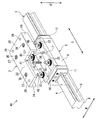
図1、図2に示されるように、直動ガイド40は、少なくとも1つ以上の軌道レール(軌道体)1と、軌道レール1上をその延在方向に沿って移動可能な複数のブロック(移動体)2と、ブロック2上に連結されるアッパープレート(取付体)3と、を備えている。
尚、ブロック2は、1つの軌道レール1上に該軌道レール1の延在方向に離間して複数設けられたり、並行する複数の軌道レール1上のそれぞれに設けられたり、これらの組み合わせで設けられる。図1及び図2では、軌道レール1及びブロック2を各1つずつ示している。
(First embodiment)
Hereinafter, the
As shown in FIGS. 1 and 2, the
A plurality of
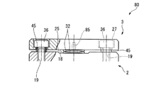
以下の説明においては、軌道レール1、ブロック2及びアッパープレート3が互いに重なり合う方向を高さ方向H(図2における上下方向)と言い、この高さ方向Hのうちアッパープレート3側を上側、軌道レール1側を下側と言う。また、高さ方向Hに垂直な面方向のうち、軌道レール1が延在する方向を長さ方向Lと言い、長さ方向Lに垂直な方向を幅方向W(図2における左右方向)と言う。
尚、本実施形態では、高さ方向Hが鉛直方向となっており、高さ方向Hに垂直な面方向が水平面方向となっている。
In the following description, the direction in which the
In the present embodiment, the height direction H is the vertical direction, and the surface direction perpendicular to the height direction H is the horizontal plane direction.
図2において、軌道レール1は、長さ方向Lに垂直な断面が略矩形状をなしている。軌道レール1の外面のうち、高さ方向Hの上側を向く上面4、及び、下側を向く下面5は、研削レスな平面(すなわち仕上げ加工が施されていない平面)となっている。また、軌道レール1の外面のうち、幅方向Wを向く一対の側面6は、その高さ方向Hの中央部が上部及び下部よりも窪まされている。側面6の上部には、長さ方向Lに沿って延びる凹溝状の転動体転走面7が複数形成されている。
In FIG. 2, the
軌道レール1には、高さ方向Hに延びるとともに上面4及び下面5に開口する貫通孔8が、長さ方向Lに間隔をあけて複数形成されている。貫通孔8は、軌道レール1を当該直動ガイド40の設置箇所であるベース部(不図示)に取り付ける際に使用されるものであり、設置時においてボルト等が挿通される。また、軌道レール1をベース部に設置することにより、該軌道レール1の下面5がベース部の取付面に当接することから、該下面5は軌道レール1の設置面となる。
A plurality of through-
ブロック2は、直方体状のブロック本体9と、ブロック本体9を長さ方向Lの両側から挟むように一対配設される平板状のエンドプレート11と、を備えている。
図2において、ブロック本体9は、長さ方向Lに垂直な断面が下側に向けて開口するC字状又はコ字状をなしており、その長さ方向Lに延在するとともに下側に向けて開口された凹溝状の凹部12に、軌道レール1の上部が収容可能とされている。
The
In FIG. 2, the
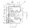
図4に示されるように、ブロック2の凹部12には、軌道レール1の転動体転走面7に対向するように長さ方向Lに沿って延びる負荷転動体転走面13が複数形成されている。
また、軌道レール1の転動体転走面7と、該転動体転走面7に対向配置される負荷転動体転走面13とにより形成される空間(長さ方向Lに延在する室)が、負荷転動体転走路14となっている。
また、凹部12内において下側を向く奥面16と軌道レール1の上面4との間には、隙間が形成されている。また、凹部12内において幅方向Wを向く内側面37と軌道レール1の側面6との間にも、隙間が形成されている。
As shown in FIG. 4, a plurality of load rolling element
Further, a space (a chamber extending in the length direction L) formed by the rolling
Further, a gap is formed between the
また、負荷転動体転走路14は、ブロック2内に形成された無端の長円環状又は楕円環状をなす無限循環路において、長さ方向Lに延びる一対の直線状部分のうち一方の直線状部分を形成している。また、無限循環路における他方の直線状部分は転動体戻り通路とされている。また、無限循環路のうち、一対の直線状部分の端部同士を連結する半円弧状の曲線状部分は転動体方向転換路とされており、転動体方向転換路は、無限循環路の長さ方向Lの両端に一対形成されている。尚、図4では、無限循環路のうち負荷転動体転走路14以外の図示を省略している。
Further, the loaded rolling
また、ブロック2に形成された無限循環路のうち、負荷転動体転走路14及び前記転動体戻り通路は、ブロック本体9に対応する部位に形成されている。また、前記転動体方向転換路は、エンドプレート11に対応する部位に形成されている。
Of the endless circulation path formed in the
また、ブロック2の無限循環路内には、該ブロック2と軌道レール1との間で転走(転動)する複数のボール(転動体)15が保持されている。これらボール15は、前述のように構成された無限循環路内に略隙間無く配設されて、路内を循環自在とされている。そして、これらボール15を介して、軌道レール1上にブロック2が連結されているとともに、ボール15の転走及び循環によって、軌道レール1上をブロック2が往復移動可能とされている。
A plurality of balls (rolling elements) 15 that roll (roll) between the
図1において、ブロック2の上面(載置面)17は、矩形状をなしており、その幅方向Wの中央部は両端部よりも一段窪まされた凹部18となっている。また、上面17における前記両端部は、研削レスの平面となっている。図2において、上面17の前記両端部には、該上面17の四隅に位置するようにネジ穴19が4つ穿設されている。尚、ネジ穴19は、上面17に四箇所穿設されていればよく、該上面17の四隅に配置されていなくても構わない。
In FIG. 1, the upper surface (mounting surface) 17 of the
また、上面17の凹部18における幅方向Wの両端部には、一対の壁部38が形成されている。壁部38は、幅方向Wに沿う凹部18中央から外側へ向かうに従い漸次上側へ向かって傾斜して形成されている。
In addition, a pair of
アッパープレート3は、矩形板状のプレート本体23と、プレート本体23の幅方向Wの両端部から垂下して長さ方向Lに沿って延びる帯板状の側面部(取付体側面部)24と、を備えている。
The
プレート本体23は、ブロック2の上面17から離間して該ブロック2の上方に配設されており、該プレート本体23の下面25とブロック2の上面17との間には、後述するカラー41及び皿バネ32を配設するためのスペースが形成されている。プレート本体23には、高さ方向Hに延びるとともに上面26及び下面25に開口する多段状の貫通孔27が、ブロック2のネジ穴19に対応する位置にそれぞれ形成されている。貫通孔27は、プレート本体23の上面26に開口する大径部分と、プレート本体23の下面25に開口する小径部分と、これら大径部分及び小径部分の間に位置して上方を向く円環状の段部と、を備えている。
The
プレート本体23の4つの貫通孔27には、ボルト(連結部)36がそれぞれ挿通されている。ボルト36は、例えば六角穴等のねじ回し手段が形成された大径のヘッド部と、外周に雄ネジ加工が施された小径の首部と、を備えている。ボルト36は、アッパープレート3を貫通するとともにブロック2のネジ穴19にねじ作用により嵌合されており、これにより、アッパープレート3とブロック2とが連結されている。
Bolts (connection portions) 36 are respectively inserted into the four through
具体的に、ボルト36のヘッド部は、貫通孔27の大径部分に収容されているとともに、該貫通孔27の段部に上側から当接している。また、ボルト36の首部は、貫通孔27の小径部分に挿通され、その先端部(下端部)がネジ穴19にねじ込まれている。これらボルト36は、ブロック2の上面17の四箇所に配置されており、ネジ穴19へのねじ込み量(締め込み量)が調整されることによって、ブロック2とアッパープレート3の相対姿勢を変更可能に、これらを連結している。
Specifically, the head portion of the
また、プレート本体23の貫通孔27の小径部分には、円筒状のカラー45が挿入されている。カラー45内には、ボルト36の首部(ネジが形成された小径部分)が挿入されており、該カラー45の下側部分は、皿バネ32内に挿入されている。また、カラー45の下端面は、ブロック2の上面17に当接しており、カラー45の上端面は、ボルト36のヘッド部(大径部分)の下端面に当接している。すなわち、ボルト36、カラー45及び皿バネ32は、ネジ穴19と共通軸となるように互いに同軸に配設されており、ボルト36及びカラー45は、皿バネ32を貫いて配置されている。
A
カラー45は、ネジ穴19に対するボルト36のねじ込み量が所定以下(所定範囲)となるように規定しており、図2に示される状態(カラー45の上端面にボルト36のヘッド部が当接し、カラー45の下端面が上面17に当接している状態)で、ボルト36が、ネジ穴19に対してそれ以上ねじ込まれることが規制されている。このようなカラー45によって、製造時やメンテナンス時などにボルト36を締め込んだ際、アッパープレート3がブロック2に対して接近し過ぎないようになっているとともに、ボルト36の締め込み量が簡単に規定されるようになっている。
The
カラー45は、ブロック2の上面17とアッパープレート3の下面25との距離が所定範囲となるようにボルト36の締め込み量を規制している一方、これら上面17と下面25との相対的な接近・離間を規制してはいない。ブロック2の上面17とアッパープレート3の下面25との相対的な接近は、後述する皿バネ(弾性体)32及びカラー(支承部)41により規制されており、ブロック2の上面17とアッパープレート3の下面25との相対的な離間は、ボルト36により規制されている。つまり、複数のボルト36は、ブロック2とアッパープレート3の最大距離を規定している。
The
図1において、プレート本体23には、高さ方向Hに延びるとともに少なくとも上面26に開口する取付穴29が複数形成されている。図示の例では、取付穴29は、プレート本体23における貫通孔27の長さ方向Lの両外側に位置するように、計4つ形成されている。これら取付穴29にボルト等が挿入されて、プレート本体23の上面26に運動させるテーブル等の目的部材(対象物)が載置される。
直動ガイド40は、アッパープレート3及びこれを支持するブロック2が軌道レール1上を往復移動することにより、前記目的部材を軌道レール1に沿って案内し、搬送する。
In FIG. 1, a plurality of mounting
The
図2において、アッパープレート3の側面部24は、ブロック2の側面21部分を幅方向Wから覆うように形成されている。詳しくは、側面部24は、側面21の上端部に対向するように配置されている。
In FIG. 2, the
図2及び図4において、側面21部分(前記側面21の上端部)と側面部24との間には、ブロック2とアッパープレート3との相対的な所定範囲の揺動を許容する隙間Cが形成されている。隙間Cは、前記揺動のうち特にローリング方向やヨーイング方向の揺動を許容可能に設定されている。本実施形態では、アッパープレート3の幅寸法(幅方向Wの外形寸法)が50mm程度であり、これに対して、隙間Cが0.5mm程度となっている。
2 and 4, a gap C that allows the
そして、ブロック2とアッパープレート3との間には、ブロック2とアッパープレート3とを離間させるカラー(支承部)41及び皿バネ(弾性体)32が配置されている。詳しくは、カラー41は、ブロック2の上面17とアッパープレート3の下面25とが所定間隔以下に接近することを規制するように、上面17と下面25との間に配設されている。カラー41は、ブロック2とアッパープレート3の相対姿勢を変更可能に支持するように、ブロック2とアッパープレート3のいずれか一方に、高さ方向Hに向けて(本実施形態では下方に向けて)突出して形成されている。
Between the
図2の例では、カラー41はアッパープレート3と一体に設けられており、図4の例では、カラー41はアッパープレート3と別体に設けられている。具体的に、カラー41において、ブロック2とアッパープレート3とが対向する高さ方向Hのうち一方を向く面(先端面)は、突出形状(凸形状)をなすとともにブロック2及びアッパープレート3のいずれかに当接可能となっている。
In the example of FIG. 2, the
図2及び図3に示されるように、アッパープレート3のプレート本体23には、下面25から下側へ向けて突出する円柱状のカラー41が、該プレート本体23に一体に形成されている。カラー41とアッパープレート3とは、例えば冷間鍛造により一体に製作されている。そして、カラー41の下面(一方を向く面)42が、突出形状をなすとともに、ブロック2の上面17の凹部18に対して隙間Gをあけて当接可能とされている。
As shown in FIGS. 2 and 3, the plate
図3において、カラー41の下面42は、上面17の凹部18に略平行に対向配置された円形状の平面からなる座面42aと、該座面42aを囲むように円環状に形成されたテーパ面42bと、を備えている。テーパ面42bの断面形状は、座面42aから幅方向Wに離間するに従い漸次上側へ向かって傾斜している。
尚、座面42aと凹部18との隙間Gは、皿バネ(弾性体)32の弾性変形にともなって、座面42aと凹部18とが互いに当接可能な所定範囲の寸法に設定されている。
In FIG. 3, the
The gap G between the
図1及び図2において、皿バネ32は、カラー41を中心にその周囲に複数配置されている。皿バネ32は、ブロック2とアッパープレート3の間に配置されて、ブロック2とアッパープレート3を離間させている。皿バネ32は、ブロック2のネジ穴19の位置に対応して、上面17における四箇所に配設されているとともに、それぞれのネジ穴19上において高さ方向Hに複数個ずつ積層されている。
1 and 2, a plurality of disc springs 32 are arranged around the
具体的に、皿バネ32は、円環板状をなしているとともに、その外周縁部の位置と内周縁部の位置とが高さ方向H(皿バネ32の中心軸方向)にずらされるようにテーパ状に形成されていて、高さ方向Hに弾性変形可能となっている。そして、高さ方向Hに隣り合う皿バネ32同士は、互いの外周縁部同士及び内周縁部同士を当接させた状態で、互い違いとなるように積層されている。
Specifically, the
また、同一のネジ穴19に対応して積層される皿バネ32の数は偶数個とされている。
これにより、積層された皿バネ32のうち、最も上方に位置する皿バネ32の外周縁部がプレート本体23の下面25に当接され、最も下方に位置する皿バネ32の外周縁部がブロック2の上面17に当接されて、下面25及び上面17と皿バネ32との当接範囲が確保される。また、皿バネ32は、カラー45を介して前記ボルト36の首部に貫かれている。
Further, the number of disc springs 32 stacked corresponding to the
As a result, of the stacked disc springs 32, the outer peripheral edge of the
図示の例では、1つのボルト36に対して、4つの皿バネ32が積層状態で配設されている。そして、これら皿バネ32のうち、上端に位置する皿バネ32がアッパープレート3の下面25における貫通孔27の開口縁部に当接し、下端に位置する皿バネ32がブロック2の上面17におけるネジ穴19の開口縁部に当接している。これら皿バネ32には、ボルト36がネジ穴19にねじ込まれることにより予圧が付与されており、アッパープレート3の上方からブロック2に向けて、前記予圧を超える外力が加えられたときにこれら皿バネ32が弾性変形して、ブロック2に対するアッパープレート3の接近を許容するようになっている。
In the illustrated example, four disc springs 32 are disposed in a stacked state with respect to one
以上説明したように、本実施形態の直動ガイド40によれば、少なくとも1つ以上の軌道レール1に、該軌道レール1上を移動可能な複数のブロック2が設けられているにも係わらず、下記の優れた効果を奏する。
すなわち、本実施形態で説明したように、複数のブロック2がテーブル等の対象物に連結されているとともに、軌道レール1に沿ってこの対象物を一体に搬送する場合においては、軌道レール1の設置場所の凹凸や剛性の有無、設置場所の温度変化などによって、直動ガイドの取り付けや動作に誤差が生じることがある。
As described above, according to the
That is, as described in the present embodiment, when the plurality of
本実施形態の直動ガイド40によれば、ブロック2とアッパープレート3の相対姿勢を変更可能に連結する複数のボルト36が設けられているので、各ブロック2のアッパープレート3がテーブル等の対象物に連結された状態で、取り付け誤差(ミスアライメント)が生じた場合であっても、これらボルト36のねじ込み量をそれぞれ調整することによって、取り付け誤差を簡単に解消できる。具体的には、ボルト36のヘッド部がカラー45の上端面に当接した状態(締め込み状態)から、必要に応じて、各ボルト36のネジ穴19に対するねじ込み量が浅くなるようにねじを緩めればよい。
According to the
これにより、ブロック2に対して、アッパープレート3をピッチング方向及びローリング方向に簡単にアライメントできる。また、アッパープレート3をブロック2から離間させたり、カラー45の高さを変更しアッパープレート3をブロック2に接近させたりすることで、ブロック2とアッパープレート3との距離を容易に変更できる。
Thereby, the
また、ブロック2とアッパープレート3の間に、これらブロック2とアッパープレート3を離間させる複数の皿バネ32が配置されているので、直動ガイド40の動作に誤差が生じた場合であっても、皿バネ32が弾性変形してアッパープレート3とブロック2とを相対的に揺動させ、このような誤差を簡単に吸収できる。従って、モーメント荷重に起因する装置への負荷を効果的に除去することができ、部品等の故障が防止される。尚、前述したようにボルト36のねじ込み量を浅く調整する際においては、皿バネ32が復元変形することから、その戻り代を十分に確保しておく(予め皿バネ32を十分に弾性変形させておく)ことにより、ボルト36の調整に係わらず皿バネ32に予圧を確実に付与することができ、好ましい。
Further, since a plurality of disc springs 32 for separating the
このように、本実施形態の直動ガイド40によれば、装置としての剛性が十分に確保されつつ、ピッチング方向及びローリング方向などのあらゆる方向のモーメント荷重を負荷することができ、誤差を十分に吸収してスムースで安定した動作が確保され、装置寿命の延長が期待できるという優れた効果を奏する。
そして、取付面(軌道レール1を設置する場所)の誤差によって生じる(ブロック2に作用する)モーメント荷重を緩和でき、かつ、モーメント荷重の負荷が作用した時に剛性を調整維持できるのである。
As described above, according to the
The moment load caused by the error of the mounting surface (where the
また、ボルト36は、ブロック2の上面17の四箇所に配置されているので、前述したピッチング方向及びローリング方向のアライメントが、精度よく簡単に行える。すなわち、例えば従来のように、ボルト36が二箇所の場合は、ピッチング方向及びローリング方向のうちいずれか一方向へのアライメントしか行えず、また三箇所の場合は、調整に熟練を要するので、作業が難しい。一方、本実施形態のようにボルト36が四箇所配置されていれば、あらゆる方向へのアライメントが容易に、かつ、高精度に行える。尚、ボルト36が五箇所以上の場合には、調整作業が煩雑となり、また製造費用が嵩むことになる。
In addition, since the
また、皿バネ32が、アッパープレート3とブロック2とを連結するボルト36に貫かれて配設されているので、該皿バネ32は、アッパープレート3とブロック2とが対向する高さ方向Hに交差する水平面方向に大きく移動してしまうようなことが防止されている。すなわち、この構成によれば、アッパープレート3とブロック2とを連結するためのボルト36を利用して、皿バネ32の位置を所定の位置に安定させることができるので、部品点数の増加を抑えつつ、皿バネ32の効果を長期に亘り安定して得ることができる。
Further, since the
また、ブロック2とアッパープレート3の相対姿勢を変更可能に支持するカラー41が設けられており、アッパープレート3は、ブロック2上にカラー41に支承されるように配設されている。また、このカラー41において一方を向く面(下面42)が突出形状とされているとともに、ブロック2に当接可能とされている。これにより、下記の効果を奏する。
Further, a
すなわち、ボルト36及び皿バネ32によって前述した効果を奏しつつ、アッパープレート3にブロック2に向けて所定以上の外力が加わった際には、カラー41の下面42がブロック2の凹部18に当接されて、アッパープレート3とブロック2とが互いに接近し過ぎるようなことが抑制される。また、カラー41がブロック2に当接することによって、該カラー41が外力を受けるとともに、過大な力が皿バネ32にかかることが抑制される。従って、皿バネ32の性能が長期に亘り安定して維持される。さらに、アッパープレート3は、カラー41がブロック2に当接した状態で、該カラー41を中心にブロック2に対して揺動可能とされている。
In other words, the
これにより、アッパープレート3は、ブロック2に対してピッチング方向及びローリング方向に揺動可能であるから、例えば軌道レール1を設置する場所(ベース部)に凹凸があったり、剛性が確保されていなかったり、温度変化による変位が生じたりすることによって、直動ガイド40の取り付けや動作に誤差が生じた場合であっても、このような誤差をアッパープレート3とブロック2との相対的な揺動により吸収できる。従って、モーメント荷重に起因する装置への負荷を効果的に除去することができ、部品等の故障が防止される。また、本実施形態の構成によれば、あらゆる方向のモーメント荷重を負荷しつつ、所定以上の外力に対する剛性をも確保しているから、前述の効果が確実に、かつ、長期に亘り安定して得られるのである。
As a result, the
さらに、ブロック2とアッパープレート3との間には、カラー41の周辺に皿バネ32が配設されている。これにより、カラー41がブロック2とアッパープレート3との距離を確保するように、水平面方向の中央の負荷を受け、皿バネ32がカラー41の負荷を分散させるように該カラー41回りの負荷を受けるので、前述の揺動を必要最小限に抑えて装置の剛性を確保でき、動作時におけるがたつき等も抑制できる。従って、ブロック2は、軌道レール1上をスムースに安定して移動できる。
Further, a
具体的に、この直動ガイド40は、ラジアル方向荷重をプレート本体23中央のカラー41で負荷することにより、剛性を確保している。また、ピッチング方向及びローリング方向のモーメント荷重については、アッパープレート3の側面部24若しくはカラー45を締め込んだボルト36のヘッド部を支持点として荷重を負荷することにより、剛性を確保している。また、水平方向荷重、ヨーイング方向のモーメント荷重については、アッパープレート3の側面部24で荷重を負荷することにより、剛性を確保している。
そして、このように剛性が十分に確保されつつも構成が簡単であるから、製造費用が抑えられる。
Specifically, the
And since the structure is simple while the rigidity is sufficiently ensured in this way, the manufacturing cost can be reduced.
また、カラー41が、ブロック2とアッパープレート3との間において水平面方向の中央に位置しているので、モーメント荷重をブロック2中心(水平面方向の中央)で負荷することができる。従って、アッパープレート3に偏荷重(モーメント荷重)が加わった際に、ブロック2を介して軌道レール1に偏荷重が加えられるようなことが防止され、ブロック2と軌道レール1との相対移動が高精度に安定して維持される。
Further, since the
また、カラー41の下面42とブロック2の上面17の凹部18との間に隙間Gが設けられているから、誤差をより吸収しやすい。
また、下面42の座面42aが、凹部18に対して面接触するように形成されているから、モーメント荷重により強くなり、剛性が向上する。
Further, since the gap G is provided between the
In addition, since the
また、弾性体として皿バネ32を用いているので、ブロック2とアッパープレート3との間のスペースが小さい場合であっても、大きなバネ定数を確保することができる。よって、装置の剛性を確実に高めることができる。
Further, since the
また、複数の皿バネ32を積層しているので、剛性と誤差吸収のバランスを簡便に調整可能である。本実施形態では、皿バネ32を積層する構成によって、十分に剛性が確保されつつも、例えば高さ方向Hに0.2mm〜0.3mm程度の大きな誤差を吸収できる。 In addition, since a plurality of disc springs 32 are stacked, the balance between rigidity and error absorption can be easily adjusted. In the present embodiment, the configuration in which the disc springs 32 are stacked can absorb a large error of, for example, about 0.2 mm to 0.3 mm in the height direction H, while ensuring sufficient rigidity.
また、ブロック2の上面17上の同一箇所(同一のネジ穴19上)に積層される皿バネ32の数が、偶数個とされており、これら積層された皿バネ32のうち、最も上方に位置する皿バネ32の外周縁部がプレート本体23の下面25に当接され、最も下方に位置する皿バネ32の外周縁部がブロック2の上面17に当接されて、下面25及び上面17と皿バネ32との当接範囲が広く確保されている。従って、皿バネ32が、アッパープレート3とブロック2との間で力を受けやすく、前述した効果がより確実に得られやすい。
The number of disc springs 32 stacked at the same location (on the same screw hole 19) on the
また本実施形態のように、軌道レール1とブロック2とが、ボール15を介して相対移動する構成においては、従来では、ボール15、転動体転走面7及び負荷転動体転走面13(負荷転動体転走路14)等の損傷を防止するため、取り付け誤差を多くても数十μm程度になるべく小さく抑える必要があり、よって軌道レール1のブロック2とは反対側を向く設置面(下面5)を仕上げ加工する必要があった。一方、本実施形態の直動ガイド40によれば、前述のように誤差を十分に吸収できるので、軌道レール1の設置面を仕上げ加工する必要がない。よって、軌道レール1の製造が簡便であるとともに、費用削減の効果が得られる。
また同様に、ブロック2の上面17、アッパープレート3の下面25及び上面26についても仕上げ加工を省略可能である。
Moreover, in the structure which the
Similarly, finishing can be omitted for the
また、前述のように大きな誤差を吸収できることから、直動ガイド40を使用するユーザーが、設置の際、アッパープレート3の上面26に前記目的部材(テーブル等の対象物)を特別な調整なく簡便に装着できる。
Further, since a large error can be absorbed as described above, a user using the
また、アッパープレート3には、ブロック2の側面21部分を覆うように側面部24が形成され、側面21部分と側面部24との間には、ブロック2とアッパープレート3との相対的な所定範囲の揺動を許容する隙間Cが形成されているので、下記の効果を奏する。
Further, the
すなわち、ブロック2とアッパープレート3との相対的な揺動(特にローリング方向やヨーイング方向の揺動)が所定範囲内である場合には、この揺動が隙間Cに吸収され、許容される。一方、前記揺動が所定範囲を超える場合には、ブロック2の側面21部分にアッパープレート3の側面部24が当接して、それ以上の揺動を規制するようになっている。これにより、ローリング方向及びヨーイング方向の大きな荷重については、カラー41及び弾性部以外に、剛性の高いブロック2とアッパープレート3との当接により負荷することができる。従って、装置の剛性が向上するとともに、その性能が高精度に安定して維持される。
In other words, when the relative swing between the
また、複数のボルト36が、ブロック2とアッパープレート3の最大距離を規定しているので、皿バネ32に確実に予圧を付与することができるとともに、アッパープレート3に対してブロック2に向けて所定以上の外力が加えられた際に、該皿バネ32を弾性変形させることで、誤差を吸収できる。よって、この直動ガイド40は、動作時のがたつきが抑制されつつ、誤差が精度よく吸収されて、動作が安定する。
Further, since the plurality of
また、ボルト36の締め込み量を規制するカラー45が設けられているので、ボルト36を締め込む際、ブロック2の上面17とアッパープレート3の下面25との距離が所定範囲となるように容易に調整できる。
Further, since the
ここで、図4を参照して、直動ガイド40のカラー41の変形例について説明する。
図4に示される例では、アッパープレート3のプレート本体23には、下面25から下側へ向けて突出する突起39が形成されている。また、ブロック2の上面17における幅方向Wの中央部は、前述した凹部18を有さない平面となっている。
Here, a modification of the
In the example shown in FIG. 4, the
また、ブロック2とアッパープレート3との間には、ブロック2とアッパープレート3との相対姿勢を変更可能に支持するようにこれらを離間させるとともに、これらブロック2及びアッパープレート3とは別体とされた円板状のカラー41が配設されている。そして、カラー41の高さ方向Hを向く両面のうち、下面(一方を向く面)42が、半球状(突出形状)とされているとともにブロック2の上面17に接して(当接可能とされて)いる。尚、ここで言う前記半球状とは、球面を2等分した半球面の形状のみを意味するものではなく、例えば、球面の一部を切り取ったように形成される曲率の小さな凸曲面状や、緩やかな勾配を有する膨出面状をも含む概念である。図示の例では、半球状の下面42は、下面視円形状をなし、球面の一部を切り欠いたように形成された曲率の小さな凸曲面である。
Further, the
また、カラー41の高さ方向Hを向く両面のうち、上面(他方を向く面)43は、円環状の平面となっているとともに、プレート本体23の下面25に当接している。カラー41の上面43の水平面方向の中央には、円穴44が形成されており、円穴44には、突起39が嵌合されている。
Of the two surfaces facing the height direction H of the
この変形例によれば、カラー41の半球状の下面42がブロック2の上面17上を転がるように作用して、アッパープレート3はブロック2に対して揺動可能とされている。よって、前述同様の作用効果が得られる。
また、無限循環路の負荷転動体転走面13が形成されるブロック2には、焼き入れ処理が施されていることから、このようにカラー41の下面42が半球状とされて点接触するようにブロック2の上面17に接する場合であっても、該上面17が負荷により変形しにくくなっている。従って、前述の揺動による効果が長期に亘り安定して得られる。
According to this modification, the hemispherical
Further, since the
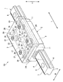
(第2実施形態)
次に、本発明に係る運動装置の第2実施形態である直動ガイド50について、図5及び図6を参照して説明する。尚、前述の実施形態と同一部材には同一の符号を付し、その説明を省略する。
(Second Embodiment)
Next, the
本実施形態の直動ガイド50は、主に下記の点で、前述した直動ガイド40とは異なっている。
The
ブロック2の幅方向Wを向く側面21には、該側面21に開口するとともにネジ穴19に連通する止めネジ穴22が複数形成されている。止めネジ穴22には、不図示のイモネジが配設され、収容される。前記イモネジは、その先端がボルト36の首部に当接することにより、該ボルト36の緩みを防止している。
ブロック2の側面21の上端部、及び、この上端部に開口する止めネジ穴22は、アッパープレート3の側面部24に覆われている。
A plurality of set screw holes 22 that open to the
The upper end portion of the
また、アッパープレート3の貫通孔27には、カラー45は設けられておらず、ボルト36は、ブロック2の上面17とアッパープレート3の下面25との距離が所定範囲となるように締め込まれた後、前記イモネジの作用により固定される。
Further, the
また、プレート本体23には、高さ方向Hに延びるとともに上面26及び下面25に開口するピン挿通孔28が、該プレート本体23の水平面方向の中央に形成されている。詳しくは、ピン挿通孔28は、ブロック2の上面17における幅方向W及び長さ方向Lの中央部に対応する位置に形成されている。
In addition, a
ピン挿通孔28には、所定の剛性を有するとともに弾性変形可能な円柱状のピン30が嵌合されている。ピン30の下端部は、プレート本体23の下面25から突出している。
A
そして、本実施形態では、ブロック2とアッパープレート3との間には、前述したカラー41の代わりに、ブロック2とアッパープレート3とが対向する高さ方向Hのうち一方(本実施形態では下方)に向けて突出する形状を有するカラー(支承部)31が設けられている。具体的に、カラー31において、高さ方向Hのうち一方を向く面(下面35)が、突出形状をなすとともにブロック2に当接可能とされている。カラー31は、前述のカラー41同様に、ブロック2とアッパープレート3との相対姿勢を変更可能に支持するように、これらを離間させている。
In this embodiment, between the
カラー31は、円板状をなしており、その外径が凹部18の幅よりも僅かに小さく設定されている。カラー31は、ピン挿通孔28と同軸に、アッパープレート3の下面25における水平面方向の中央に配置されている。カラー31の外周面における下端部は、凹部18の壁部38に接近して配置されている。
The
本実施形態では、カラー31の高さ方向Hを向く両面のうち、下面35が、半球状とされているとともにブロック2の上面17に接している。図示の例では、半球状の下面35は、球面の一部を切り欠いたように形成された曲率の小さな円形状の凸曲面である。
また、カラー31の高さ方向Hを向く両面のうち、上面34は、円環状の平面となっているとともに、プレート本体23の下面25に当接している。
In the present embodiment, of the both surfaces of the
Of the two surfaces facing the height direction H of the
また、カラー31の水平面方向の中央には、その中心軸が高さ方向Hに延びるとともに上面34に開口するピン取付穴33が形成されている。ピン取付穴33には、前記ピン30が嵌合されており、このピン30を介して、カラー31がアッパープレート3に一体とされている。
Further, a
本実施形態の直動ガイド50においても、前述した直動ガイド40と同様の作用効果を奏する。
Also in the
また、カラー31が、ピン30を介してアッパープレート3に一体とされているので、ブロック2とアッパープレート3との間における該カラー31の位置が水平面方向の中央に精度よく決まる。よって、前述の効果が精度よく得られる。
Further, since the
また、カラー31、弾性体(皿バネ32)、及び、ピン30によりアライメント機構を廉価かつ簡単に作製できる。
尚、特に図示しないが、カラー31のピン取付穴33は、該カラー31を高さ方向Hに貫通して形成されていてもよい。この場合、カラー31の下面35のうちピン取付穴33の下端開口縁と、ブロック2の上面17とは、円環状に線接触するように当接することになり、ブロック2から受ける負荷がカラー31の周方向に分散されやすくなり、該カラー31の変形や破損が防止される。
In addition, the alignment mechanism can be manufactured inexpensively and easily by the
Although not particularly illustrated, the
(第3実施形態)
次に、本発明に係る運動装置の第3実施形態である直動ガイド60について、図7及び図8を参照して説明する。尚、前述の実施形態と同一部材には同一の符号を付し、その説明を省略する。
(Third embodiment)
Next, a
本実施形態の直動ガイド60は、主に下記の点で、前述した直動ガイド40、50とは異なっている。
The
この直動ガイド60は、前述の実施形態で説明した支承部であるカラー41、31及びボルト36のカラー45を有していない。
The
本実施形態の直動ガイド60においても、前述した直動ガイド40、50と同様の作用効果を奏する。
また、この直動ガイド60によれば、ネジ穴19に対するボルト36のねじ込み量の調整範囲を大きくとることができるとともに、アッパープレート3とブロック2との相対姿勢の変更範囲を大きくとれることから、前述の取り付け誤差をより確実に吸収できる。また、動作時においても、アッパープレート3が、支承部に規制されることなくブロック2に対して大きく移動できるから、動作時の誤差についても確実に吸収することができる。
Also in the
Further, according to the
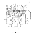
(第4実施形態)
次に、本発明に係る運動装置の第4実施形態である直動ガイド80について、図9を参照して説明する。尚、前述の実施形態と同一部材には同一の符号を付し、その説明を省略する。
(Fourth embodiment)
Next, a
本実施形態の直動ガイド80は、主に下記の点で、前述した直動ガイド40,50,60とは異なっている。
The
この直動ガイド80では、前述の実施形態で説明した皿バネ32が、ボルト36ではなく、ピン(支承部)81に貫かれている。
ピン81には、S45Cなどの焼き入れした材料が用いられる。アッパープレート3のプレート本体23には、下面25から上側へ向うピン穴83が形成され、このピン穴83にピン81が嵌合配置される。そして、ピン81の下面82は、半球形に形成されると共に、プレート本体23よりも下側に突出する。
一方、ピン81の下面82に当接するブロック2の上面17の凹部18には、半球形の穴部84が形成される。つまり、ピン81は、ブロック2の上面17に対して球面軸受(下面82、穴部84)により支持される。
これにより、直動ガイド80は、アッパープレート3に重量物が連結されることによりブロック2に高荷重が加わったとしても、ブロック2とアッパープレート3の相対姿勢を円滑に変更可能である。
In the
A hardened material such as S45C is used for the
On the other hand, a
As a result, the
また、直動ガイド80は、アッパープレート3の側面部24を有していない。4本のボルト36により、水平方向荷重、ヨーイング方向のモーメント荷重を支持可能であれば、アッパープレート3の側面部24を省くことができる。
Further, the
ここで、図10を参照して、直動ガイド80の支承部の変形例について説明する。
図10に示される例では、支承部として六角穴付きボタンボルト85が用いられている。つまり、六角穴付きボタンボルト85のボタン形のヘッド部分が支承部となる。そして、六角穴付きボタンボルト85を用いることにより、コスト低減を図ることが可能となる。なお、この場合には、上面17の凹部18は、平坦であってよい。
また、本実施形態では、支承部として六角穴付きボタンボルト85を用いているが、これと同等の機能を発揮する他の部材に変更してもよい。
Here, with reference to FIG. 10, the modification of the support part of the
In the example shown in FIG. 10, a hexagon
Moreover, in this embodiment, although the hexagon
本実施形態の直動ガイド80においても、前述した直動ガイド40、50、60と同様の作用効果を奏する。
また、この直動ガイド80によれば、アッパープレート3に重量物が連結されることによりブロック2に高荷重が加わったとしても、ブロック2とアッパープレート3の相対姿勢を円滑に変更可能である。また、アッパープレート3の側面部24を省いたり、支承部として六角穴付きボタンボルト85が用いたりすることにより、性能を維持しつつ、コスト低減を図ることができる。
Also in the
Further, according to the
(第5実施形態)
次に、本発明に係る運動装置の第5実施形態である直動ガイド90について、図11を参照して説明する。尚、前述の実施形態と同一部材には同一の符号を付し、その説明を省略する。
(Fifth embodiment)
Next, a
本実施形態の直動ガイド90は、主に下記の点で、前述した直動ガイド40,50,60,80とは異なっている。
The
この直動ガイド90は、壁面設置される。
すなわち、軌道レール1、ブロック2及びアッパープレート3が互いに重なり合う高さ方向が、水平面方向W(図11における左右方向)となる。
また、軌道レール1、ブロック2及びアッパープレート3の幅方向が、鉛直方向H(図11における上下方向)となる。
軌道レール1が延在する方向は、長さ方向Lのままである。
The
That is, the height direction in which the
Moreover, the width direction of the
The direction in which the
そして、直動ガイド90では、アッパープレート3は、壁面配置した際の垂直荷重をブロック2で支持するために、ブロック本体9の上側の側面21に当接する垂直荷重支持部91を有している。
垂直荷重支持部91は、上面部92と、上面部92の下面に配置された六角穴付きボタンボルト93とから構成される。
上面部92は、アッパープレート3の上側端から、ブロック本体9の上側の側面21に対向するように形成されている。上面部92とブロック本体9の側面21との間には、隙間が形成される。そして、上面部92の下面に取り付けられた六角穴付きボタンボルト93のボタン形のヘッド部分がブロック本体9の上側の側面21に当接する。
このように、直動ガイド90では、垂直荷重支持部91を設けることにより、アッパープレート3の自重及び及びアッパープレート3に加わる負荷の鉛直方向成分がブロック本体9により直接支持される。これにより、直動ガイド90を壁面設置したとしても、ブロック2とアッパープレート3の相対姿勢を変更可能にすることができる。
In the
The vertical
The
Thus, in the
本実施形態の直動ガイド90においても、前述した直動ガイド40、50、60,80と同様の作用効果を奏する。
特に、この直動ガイド90によれば、垂直荷重支持部91として、上面部92と六角穴付きボタンボルト93と用いたので、コスト上昇を招くことなく、直動ガイド90の壁面設置を実現できる。
Also in the
In particular, according to this
なお、直動ガイド90を設置する壁面は、垂直面に限定されることはなく、傾斜した面であればよい。
また、垂直荷重支持部91は、六角穴付きボタンボルト93を設ける場合に限らない。上面部92の下面に突起部を一体的に形成して、この突起部をブロック本体9の側面21に当接させてもよい。また、上面部92の形状は、平板形に限らず、フック形状等であってもよい。
Note that the wall surface on which the
Further, the vertical
本発明は、第1から第5実施形態に限定されるものではなく、本発明の趣旨を逸脱しない範囲において種々の変更を加えることが可能である。 The present invention is not limited to the first to fifth embodiments, and various modifications can be made without departing from the spirit of the present invention.
例えば、前述の実施形態では、ブロック2の上面17の四隅にネジ穴19が計4つ穿設されているとともに、これらネジ穴19の位置に対応してボルト36及び皿バネ32がそれぞれ設けられているとしたが、これらの数や位置は限定されない。すなわち、皿バネ32及びボルト36は、上面17における複数個所に設けられていればよく、また上面17の四隅に配置されていなくても構わない。
また、これら皿バネ32とボルト36とは、互いに同一箇所に配置されていなくても構わない。ただし、皿バネ32とボルト36とが同一箇所に配置され、皿バネ32がボルト36に貫かれていることにより、前述の実施形態で説明した効果が得られることから好ましい。
また、前述した実施形態のように、皿バネ32及びボルト36がカラー31、41の周辺を囲むように設けられることにより、取り付け誤差の調整が簡単となるとともに、あらゆる方向のモーメント荷重を負荷しやすくなることから、好ましい。
また、アッパープレート3の取付穴29の数も、前述した実施形態の4つに限定されない。
For example, in the above-described embodiment, a total of four
Further, the
Further, as in the above-described embodiment, the
Further, the number of mounting
また、前述の実施形態では、皿バネ32が、アッパープレート3とブロック2とを連結するボルト36に貫かれて配設されているとしたが、ボルト36以外の軸部材に貫かれていても構わない。
つまり、アッパープレート3とブロック2とが、ボルト36以外の軸部材(連結部)によって互いに連結されていてもよい。具体的に、例えば図6において、ボルト36の代わりに、周面にネジ加工が施されていない首部と該首部より大径の頭部とを有する軸部材を用いてもよい。そして、軸部材36の首部(小径部分)をブロック2におけるネジ穴19に代わる穴に挿入した状態で、ネジ穴22に代わるピン穴に打込みピンを嵌合するとともに、該打込みピンの先端を前記首部に当接させる(食い込ませる)ことにより、軸部材36の軸方向への移動を規制するようにしても構わない。
In the above-described embodiment, the
That is, the
また、前述の実施形態では、弾性体として皿バネ32を用いたが、これに限定されるものではない。すなわち、弾性体は、ブロック2とアッパープレート3の間に配置されて、ブロック2とアッパープレート3を離間させるものであればよく、例えば皿バネ32以外の、弾性を有する板バネ等の金属材料やゴム等の高分子材料であっても構わない。ただし、弾性体として皿バネ32を用いることにより、前述の実施形態で説明した効果が得られることから好ましい。
In the above-described embodiment, the
また、カラー31、41、81が、ブロック2とアッパープレート3との間において水平面方向の中央に位置していることとしたが、これに限定されるものではなく、例えば水平面方向の中央から偏倚した位置に配置されていてもよい。
In addition, the
また、負荷転動体転走路14は、ブロック2内の無限循環路の一部を形成していることとして説明したが、これに限定されるものではない。すなわち、負荷転動体転走路14は、例えばボール15の循環しない所謂有限形式の循環路の一部であっても構わない。
また、転動体としてボール15を用いて説明したが、これに限定されるものではなく、それ以外の例えば略円柱状のローラ、コロ等の転動体であってもよい。
Moreover, although the load rolling-
Moreover, although demonstrated using the ball |
また、前述の実施形態では、運動装置として直動ガイド40、50、60、80、90を例にあげて説明したが、それ以外のボールスプライン、ボールねじ等の運動装置であっても構わない。また、本発明の運動装置は、転動体を含まない単なるスライダ機構からなる案内装置をも含んでいる。 In the above-described embodiment, the linear motion guides 40, 50, 60, 80, and 90 have been described as examples of the exercise device. However, other exercise devices such as a ball spline and a ball screw may be used. . Moreover, the exercise device of the present invention also includes a guide device including a simple slider mechanism that does not include rolling elements.
その他、本発明の前述の実施形態及び変形例で説明した構成要素を、適宜組み合わせても構わない。また、本発明の趣旨を逸脱しない範囲において、前述の構成要素を周知の構成要素に置き換えることも可能である。 In addition, you may combine suitably the component demonstrated in the above-mentioned embodiment and modification of this invention. In addition, the above-described components can be replaced with well-known components without departing from the spirit of the present invention.
以下、本発明を実施例により具体的に説明する。ただし本発明はこの実施例に限定されるものではない。 Hereinafter, the present invention will be specifically described by way of examples. However, the present invention is not limited to this embodiment.
[MA(ピッチング)方向転がり抵抗確認試験]
[実施例1]
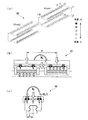
本発明の実施例1として、前述の第1実施形態で説明した直動ガイド40を用意した。
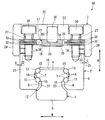
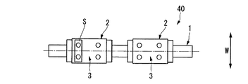
そして、図12に示すように、直動ガイド40の軌道レール1上に、長さ方向Lに間隔をあけてブロック2を一対配置した。尚、これらブロック2同士のピッチPは、350mmとした。また、アッパープレート3上に、運動させる目的部材であるテーブルTを固定した。
[MA (pitching) direction rolling resistance confirmation test]
[Example 1]
As Example 1 of the present invention, the
Then, as shown in FIG. 12, a pair of
図13に示されるように、アッパープレート3とテーブルTとの間に、シムSを挿入した。詳しくは、直動ガイド40にピッチング方向のモーメント荷重が加わりやすくなるように、シムSを配設した。
尚、図15に示すように、シムSの厚さについては、テーブルTの全長400mmに対して、0.0mm(取付誤差:0.0/400、すなわちシムS無し)のものから、1.0mm(取付誤差:1.0/400)のものまでを段階的に用意した。
As shown in FIG. 13, a shim S was inserted between the
As shown in FIG. 15, the thickness of the shim S is from 0.0 mm (mounting error: 0.0 / 400, ie, no shim S) to 1.400 mm in total length of the table T. Up to 0 mm (mounting error: 1.0 / 400) was prepared stepwise.
そして、図12に示されるロードセルLCを用いて、測定速度:5mm/s、ストローク:150mmの条件で、転がり抵抗を測定した。
結果を、図15のグラフに示す。尚、グラフの縦軸は、シムS無しの場合の転がり抵抗を基準(×1)として、該基準に対するシムS有りの場合の転がり抵抗の増加倍率を示している。
Then, using the load cell LC shown in FIG. 12, the rolling resistance was measured under the conditions of a measurement speed: 5 mm / s and a stroke: 150 mm.
The results are shown in the graph of FIG. The vertical axis of the graph shows the increase rate of the rolling resistance when the shim S is present relative to the reference, with the rolling resistance when the shim S is absent as a reference (× 1).
[比較例1]
一方、比較例1として、カラー41、45、皿バネ32及びアッパープレート3を有さない従来の直動ガイドを用意した。そして、ブロック2上にテーブルTを固定し、シムSを、ブロック2とテーブルTとの間に配設した。それ以外は、実施例1と同じ条件として、転がり抵抗を測定した。結果を、図15のグラフに示す。
[Comparative Example 1]
On the other hand, as Comparative Example 1, a conventional linear guide having no
[MC(ローリング)方向転がり抵抗確認試験]
[実施例2]
また、本発明の実施例2として、図14に示されるように、直動ガイド40にローリング方向のモーメント荷重が加わりやすくなるように、シムSを配設した。
尚、図16に示すように、シムSの厚さについては、直動ガイド40の幅50mmに対して、0.0mm(取付誤差:0.0/50、すなわちシムS無し)のものから、1.0mm(取付誤差:1.0/50)のものまでを段階的に用意した。それ以外は実施例1と同じ条件として、転がり抵抗を測定した。結果を、図16のグラフに示す。
[MC (rolling) direction rolling resistance confirmation test]
[Example 2]
Further, as Example 2 of the present invention, as shown in FIG. 14, a shim S is disposed so that a moment load in the rolling direction is easily applied to the
As shown in FIG. 16, the thickness of the shim S is from 0.0 mm (mounting error: 0.0 / 50, ie, no shim S) with respect to the width of 50 mm of the
[比較例2]
一方、比較例2として、カラー41、45、皿バネ32及びアッパープレート3を有さない従来の直動ガイドを用意した。そして、ブロック2上にテーブルTを固定し、シムSを、ブロック2とテーブルTとの間に配設した。それ以外は、実施例2と同じ条件として、転がり抵抗を測定した。結果を、図16のグラフに示す。
[Comparative Example 2]
On the other hand, as Comparative Example 2, a conventional linear motion guide having no
[評価]
図15及び図16に示される通り、実施例1、2については、シムS厚さが1.0mmに及ぶ場合であっても、転がり抵抗増加倍率が(×10)以下となり、十分に低く抑えられることがわかった。
この結果からわかるように、本実施例の直動ガイド40によれば、例えば軌道レール1を設置する場所に凹凸があったり、設置する装置の剛性が確保されていなかったり、設置場所の温度変化によって変位が生じたりすることによって、取り付けや動作に誤差が生じることがあっても、装置としての剛性が十分に確保されつつ、あらゆる方向のモーメント荷重を負荷することができ、誤差を十分に吸収してスムースで安定した動作が確保され、装置寿命の延長が期待できる。つまり、取付面の誤差によって生じるモーメント荷重を緩和でき、かつ、モーメント荷重の負荷が作用した時に剛性を調整維持できる。
[Evaluation]
As shown in FIGS. 15 and 16, in Examples 1 and 2, even when the shim S thickness reaches 1.0 mm, the rolling resistance increase magnification is (× 10) or less and is kept sufficiently low. I found out that
As can be seen from this result, according to the
[MA方向及びMC方向モーメント荷重負荷による耐久確認試験]
[実施例3]
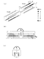
本発明の実施例3として、軌道レール1上に一対のブロック2を間隔をあけて配置した直動ガイド40を用いて、実施例1、2で説明したMA方向のモーメント荷重及びMC方向のモーメント荷重をそれぞれ所定量負荷した状態で、この直動ガイド40を繰り返し往復移動させて、負荷転動体転走面13の状態(転動(走)面の荒れ)を確認した。結果を、図17に示す。
[Endurance confirmation test by moment load in MA direction and MC direction]
[Example 3]
As a third embodiment of the present invention, using the
[比較例3]
一方、比較例3として、カラー41、45、皿バネ32及びアッパープレート3を有さない従来の直動ガイドを用意した。それ以外は、実施例3と同じ条件として、この直動ガイドを繰り返し往復移動させて、負荷転動体転走面の状態を確認した。結果を、図18に示す。
[Comparative Example 3]
On the other hand, as Comparative Example 3, a conventional linear motion guide having no
[評価]
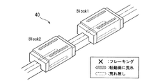
図17に示される実施例3では、往復移動の走行距離が1000kmに達した時点において、負荷転動体転走面13の一部に多少の荒れは見受けられるものの、フレーキング等の損傷は見受けられなかった。
一方、図18に示される比較例3では、往復移動の走行距離が109kmに達した時点において、負荷転動体転走面の多くに荒れが見受けられ、フレーキングも複数見受けられた。
[Evaluation]
In Example 3 shown in FIG. 17, when the traveling distance of the reciprocating movement reaches 1000 km, some roughness of the rolling surface of the loaded rolling
On the other hand, in Comparative Example 3 shown in FIG. 18, when the travel distance of the reciprocating movement reached 109 km, many of the loaded rolling element rolling surfaces were rough, and a plurality of flakings were also observed.
[MA方向及びMC方向モーメント荷重負荷による負荷分布シミュレーション]
[実施例4]
本発明の実施例4として、軌道レール1上に一対のブロック2を間隔をあけて配置した直動ガイド40を用い、実施例3と同様の条件において、負荷転動体転走面13(負荷転動体転走路14)に配列された各ボール15にかかる負荷分布シミュレーションを行った。結果を、図19(a)〜(c)に示す。
尚、図19(b)(c)において、円弧状の矢印はモーメント荷重の向きを示しており、直線状の矢印のうち、太い矢印はテーブルTから直動ガイドに加えられる外力等の向きを示し、細い矢印はこれらモーメント荷重や外力等により各部材(ボール15やカラー41)に負荷される力の大きさを長さで示している。
[Load distribution simulation by moment load in MA and MC directions]
[Example 4]
As Example 4 of the present invention, using a
In FIGS. 19B and 19C, the arc-shaped arrow indicates the direction of the moment load. Of the straight arrows, the thick arrow indicates the direction of the external force applied from the table T to the linear guide. The thin arrows indicate the magnitude of the force applied to each member (the
[比較例4]
一方、比較例4として、カラー41、45、皿バネ32及びアッパープレート3を有さない従来の直動ガイドを用意した。それ以外は、実施例4と同じ条件として、負荷分布シミュレーションを行った。結果を、図20(a)〜(c)に示す。
尚、図20(b)(c)における矢印の意味は、前述した図19(b)(c)と同様である。
[Comparative Example 4]
On the other hand, as Comparative Example 4, a conventional linear motion guide having no
In addition, the meaning of the arrow in FIG.20 (b) (c) is the same as that of FIG.19 (b) (c) mentioned above.
[評価]
図19(a)〜(c)に示されるように、実施例4においては、各ボール15にかかる荷重が小さく抑えられているとともに、全体に均一な荷重を負荷していることがわかる。
また、モーメント荷重や外力等が大きくなった場合に、カラー41が負荷を受けることで、ボール15にかかる負荷を低減させている。
一方、図20(a)〜(c)に示されるように、比較例4においては、ボール15がモーメント荷重や外力等をそのまま大きく受けているとともに、局所的な集中荷重が発生していることがわかる。
[Evaluation]
As shown in FIGS. 19A to 19C, in Example 4, it can be seen that the load applied to each
Further, when the moment load, the external force, or the like becomes large, the load applied to the
On the other hand, as shown in FIGS. 20 (a) to 20 (c), in Comparative Example 4, the
1…軌道レール(軌道体)、 2…ブロック(移動体)、 3…アッパープレート(取付体)、 40,50,60,80,90…直動ガイド(運動装置)、 17…ブロックの上面(載置面)、 24…側面部、 31,41,81…ピン(支承部)、 32…皿バネ(弾性体)、 36…ボルト(連結部)、 91…垂直荷重支持部、 C…隙間
DESCRIPTION OF
Claims (8)
前記軌道体上を移動可能な複数の移動体と、
前記移動体の載置面から離間して配置される取付体と、
前記移動体と前記取付体の間に配置されて、前記移動体と前記取付体を離間させる弾性体と、
前記移動体と前記取付体の相対姿勢を変更可能に連結する複数の連結部と、
を備えることを特徴とする運動装置。 At least one orbiting body;
A plurality of movable bodies movable on the track body;
A mounting body disposed apart from the mounting surface of the moving body;
An elastic body disposed between the moving body and the mounting body, and separating the moving body and the mounting body;
A plurality of connecting portions for connecting the movable body and the mounting body in a changeable manner; and
An exercise device comprising:
を備えることを特徴とする請求項1又は2に記載の運動装置。 A support portion projecting to one of the moving body and the mounting body so as to support the movable body and the mounting body in a changeable relative posture;
The exercise apparatus according to claim 1, further comprising:
Priority Applications (1)
| Application Number | Priority Date | Filing Date | Title |
|---|---|---|---|
| JP2012184468A JP2013083347A (en) | 2011-09-27 | 2012-08-23 | Motion device |
Applications Claiming Priority (3)
| Application Number | Priority Date | Filing Date | Title |
|---|---|---|---|
| JP2011210741 | 2011-09-27 | ||
| JP2011210741 | 2011-09-27 | ||
| JP2012184468A JP2013083347A (en) | 2011-09-27 | 2012-08-23 | Motion device |
Publications (1)
| Publication Number | Publication Date |
|---|---|
| JP2013083347A true JP2013083347A (en) | 2013-05-09 |
Family
ID=48528726
Family Applications (1)
| Application Number | Title | Priority Date | Filing Date |
|---|---|---|---|
| JP2012184468A Pending JP2013083347A (en) | 2011-09-27 | 2012-08-23 | Motion device |
Country Status (1)
| Country | Link |
|---|---|
| JP (1) | JP2013083347A (en) |
Cited By (1)
| Publication number | Priority date | Publication date | Assignee | Title |
|---|---|---|---|---|
| WO2026011398A1 (en) * | 2024-07-12 | 2026-01-15 | 郑红艳 | Linear ball slider for linear guide rail |
-
2012
- 2012-08-23 JP JP2012184468A patent/JP2013083347A/en active Pending
Cited By (1)
| Publication number | Priority date | Publication date | Assignee | Title |
|---|---|---|---|---|
| WO2026011398A1 (en) * | 2024-07-12 | 2026-01-15 | 郑红艳 | Linear ball slider for linear guide rail |
Similar Documents
| Publication | Publication Date | Title |
|---|---|---|
| US9382098B2 (en) | Elevator device and roller guide assembly | |
| CN102449333B (en) | Adjustable preload type linear guide system | |
| JP5733469B2 (en) | Single axis actuator | |
| CN101238297B (en) | Linear guide | |
| JP6728585B2 (en) | Angular contact ball bearing | |
| US9422976B2 (en) | Axial-radial rolling contact bearing, in particular for supporting rotor blades on a wind turbine | |
| US12398839B2 (en) | Adjustable leveling kit and associated installation method | |
| US11105366B2 (en) | Long span lead screw assembly with anti-backlash nut and wear compensated load bearing element | |
| US11268600B2 (en) | Linear motion guide device and method for manufacturing linear motion guide device | |
| JP2013083347A (en) | Motion device | |
| JPH0416296B2 (en) | ||
| US8770849B2 (en) | Pivoting ball bearing system | |
| CN102080690B (en) | For the spacer element with adjustable length of rolling bearing | |
| JP5324559B2 (en) | Exercise equipment | |
| CN104039628A (en) | Spindle drive for adjusting the height of an electrically adjustable steering column | |
| KR20130013040A (en) | Error compensating bearing screw conveying device | |
| JP5514001B2 (en) | Suspension upper mount device | |
| US20080279494A1 (en) | Bearing cage with oblong cavities and radial angular-contact ball bearing comprising such a cage | |
| CN220396281U (en) | Pre-tightening rolling linear guide rail capable of reducing abrasion | |
| CN112555278A (en) | Static pressure platform thrust self-aligning roller combined bearing | |
| CN215805747U (en) | Static pressure platform thrust self-aligning roller combined bearing | |
| TWI716538B (en) | Combined cylindrical roller bearing | |
| JP5208621B2 (en) | Exercise guidance device | |
| JP2010107026A (en) | Rolling device | |
| JP4178316B2 (en) | Double row eccentric thrust bearing |