JP2013083323A - Solenoid valve manifold - Google Patents

Solenoid valve manifold Download PDF

Info

Publication number
JP2013083323A
JP2013083323A JP2011224250A JP2011224250A JP2013083323A JP 2013083323 A JP2013083323 A JP 2013083323A JP 2011224250 A JP2011224250 A JP 2011224250A JP 2011224250 A JP2011224250 A JP 2011224250A JP 2013083323 A JP2013083323 A JP 2013083323A
Authority
JP
Japan
Prior art keywords
valve
valve body
axial direction
end side
hole
Prior art date
Legal status (The legal status is an assumption and is not a legal conclusion. Google has not performed a legal analysis and makes no representation as to the accuracy of the status listed.)
Pending
Application number
JP2011224250A
Other languages
Japanese (ja)
Inventor
Shinji Ito
新治 伊藤
Current Assignee (The listed assignees may be inaccurate. Google has not performed a legal analysis and makes no representation or warranty as to the accuracy of the list.)
CKD Corp
Original Assignee
CKD Corp
Priority date (The priority date is an assumption and is not a legal conclusion. Google has not performed a legal analysis and makes no representation as to the accuracy of the date listed.)
Filing date
Publication date
Application filed by CKD Corp filed Critical CKD Corp
Priority to JP2011224250A priority Critical patent/JP2013083323A/en
Publication of JP2013083323A publication Critical patent/JP2013083323A/en
Pending legal-status Critical Current

Links

Images

Abstract

PROBLEM TO BE SOLVED: To provide a solenoid valve manifold capable of increasing the flow rate of pressure fluid supplied and discharged through a solenoid valve.SOLUTION: A second side surface 32c of a valve body 32 is formed so that one end side in an axial direction of a spool valving element is more spaced from a valve port than the another end side in the axial direction while a first side surface 32b of the valve body 32 is formed so that the another end side in the axial direction is more spaced from the valve port than one end side in the axial direction of the spool valving element. An opening 38a on a counter surface 32a of a first output port 38 connected to a first output flow path 14 opened to a front surface 2b of a manifold base 2 is formed into a shape swelling out to the side of the first side surface 32b than an opening 36a on the counter surface 32a of a first exhaust port 36.

Description

本発明は、電磁弁マニホールドに関する。   The present invention relates to a solenoid valve manifold.

従来、複数の流体圧機器(例えば、エアシリンダ等)の駆動を並行して制御することが可能な電磁弁マニホールドが知られている(例えば、特許文献1)。図9に示す例では、電磁弁マニホールド91は、マニホールドベース92の載置面92a上に複数の電磁弁93を一方向に配列することにより構成されている。電磁弁93には、パイロット流体によりスプール弁体94を往復動させるパイロット形電磁弁が採用されている。   2. Description of the Related Art Conventionally, there is known an electromagnetic valve manifold capable of controlling the driving of a plurality of fluid pressure devices (for example, air cylinders) in parallel (for example, Patent Document 1). In the example shown in FIG. 9, the electromagnetic valve manifold 91 is configured by arranging a plurality of electromagnetic valves 93 in one direction on the mounting surface 92 a of the manifold base 92. The solenoid valve 93 employs a pilot-type solenoid valve that reciprocates the spool valve body 94 with a pilot fluid.

詳しくは、図10及び図11に示すように、マニホールドベース92には、圧力流体の供給源(図示略)に接続される給気流路95と、第1及び第2排気流路96,97がスプール弁体94の軸方向と直交する幅方向に沿って延設されている。そして、給気流路95には、同給気流路95から分岐して載置面92aに開口する複数の給気連通流路95aが電磁弁93毎に形成されるとともに、第1及び第2排気流路96,97には、同第1及び第2排気流路96,97から分岐して載置面92aに開口する第1及び第2排気連通流路96a,97aが電磁弁93毎にそれぞれ形成されている。また、マニホールドベース92には、載置面92aに開口し、電磁弁93と流体圧機器とを接続する第1及び第2出力流路98,99が電磁弁93毎にそれぞれ形成されている。   Specifically, as shown in FIGS. 10 and 11, the manifold base 92 includes an air supply passage 95 connected to a pressure fluid supply source (not shown), and first and second exhaust passages 96 and 97. The spool valve body 94 extends along the width direction orthogonal to the axial direction. A plurality of air communication passages 95a branched from the air supply passage 95 and opened to the mounting surface 92a are formed in the air supply passage 95 for each electromagnetic valve 93, and the first and second exhausts. The first and second exhaust communication channels 96a and 97a branched from the first and second exhaust channels 96 and 97 and opened to the mounting surface 92a are provided for the electromagnetic valves 93, respectively. Is formed. The manifold base 92 is formed with first and second output channels 98 and 99 for each electromagnetic valve 93 that open to the mounting surface 92 a and connect the electromagnetic valve 93 and the fluid pressure device.

一方、電磁弁93は、スプール弁体94が挿入される弁孔101が形成された略直方体状の弁ボディ102を備えている。弁ボディ102には、給気流路95に接続される給気ポート103と、第1及び第2排気流路96,97にそれぞれ接続される第1及び第2排気ポート104,105と、第1及び第2出力流路98,99にそれぞれ接続される第1及び第2出力ポート106,107が形成されている。各ポート103〜107は、弁孔101にそれぞれ連通するとともに、弁ボディ102におけるマニホールドベース92の載置面92aと対向する対向面102aに開口している。そして、パイロット弁部108を介して供給されるパイロット流体によりスプール弁体94が弁孔101内を往復動することで、各ポート103〜107間の連通が切り換えられるようになっている。   On the other hand, the electromagnetic valve 93 includes a substantially rectangular parallelepiped valve body 102 in which a valve hole 101 into which the spool valve body 94 is inserted is formed. The valve body 102 includes an air supply port 103 connected to the air supply passage 95, first and second exhaust ports 104 and 105 connected to the first and second exhaust passages 96 and 97, and a first First and second output ports 106 and 107 connected to the second output flow paths 98 and 99, respectively, are formed. Each of the ports 103 to 107 communicates with the valve hole 101 and opens on a facing surface 102 a facing the mounting surface 92 a of the manifold base 92 in the valve body 102. The spool valve element 94 reciprocates in the valve hole 101 by the pilot fluid supplied through the pilot valve unit 108, so that the communication between the ports 103 to 107 is switched.

図9に示すように、弁ボディ102における幅方向両側の側面102bには、それぞれ凸部111及び凹部112が形成されており、弁ボディ102の凸部111と対応する位置には、取付孔113が形成されている。そして、各電磁弁93は、凸部111が隣接する電磁弁93の凹部112に嵌合した状態で取付孔113に取付ネジ114が挿通されることによりマニホールドベース92上に固定されている。このように凸部111に取付孔113を形成することで弁孔101の内径を大きくし、各電磁弁93を介して給排される圧力流体の大流量化が可能となっている。なお、凸部111を形成することで電磁弁93単体での幅は大きくなるものの、凸部111を隣接する電磁弁93の凹部112に嵌合させることで、隣接する電磁弁93間の間隔である所謂バルブピッチが大きくなることを防止できるため、電磁弁マニホールド91全体での大型化が抑制されている。   As shown in FIG. 9, convex portions 111 and concave portions 112 are respectively formed on the side surfaces 102 b on both sides in the width direction of the valve body 102, and the mounting holes 113 are formed at positions corresponding to the convex portions 111 of the valve body 102. Is formed. Each electromagnetic valve 93 is fixed on the manifold base 92 by inserting a mounting screw 114 through the mounting hole 113 in a state where the convex portion 111 is fitted in the concave portion 112 of the adjacent electromagnetic valve 93. Thus, by forming the attachment hole 113 in the convex part 111, the internal diameter of the valve hole 101 is enlarged, and the flow volume of the pressure fluid supplied / discharged via each electromagnetic valve 93 is attained. In addition, although the width | variety in the solenoid valve 93 single-piece | unit becomes large by forming the convex part 111, by making the convex part 111 fit into the recessed part 112 of the adjacent electromagnetic valve 93, it is in the space | interval between the adjacent electromagnetic valves 93. Since it is possible to prevent an increase in a so-called valve pitch, an increase in size of the entire solenoid valve manifold 91 is suppressed.

特開平9−273651号公報JP-A-9-273651

ところで、電磁弁マニホールド91の取付性等の観点から、多くの場合、第1及び第2出力流路98,99は、マニホールドベース92におけるスプール弁体94の軸方向一端側の前面92bに開口して形成される。そのため、図11に示すように、第1出力流路98と第1排気連通流路96aとは、互いに干渉することを避けるために幅方向に並べて形成されることになる。そのため、第1出力流路98におけるスプール弁体94の軸方向に沿った直線部98aと第1出力ポート106の開口部106aとが重なる面積、及び第1排気連通流路96aの開口面積(内径)の少なくとも一方を小さくせざるを得ず、圧力流体の流量が制限されてしまう虞があった。なお、説明の便宜上、図11では、右端の電磁弁93に接続される第1出力流路98の直線部98aのみを示し、他の直線部98a及び第2出力流路99の直線部を省略している。   By the way, from the viewpoint of attachment of the solenoid valve manifold 91 and the like, in many cases, the first and second output flow paths 98 and 99 open to the front surface 92b on one end side in the axial direction of the spool valve body 94 in the manifold base 92. Formed. Therefore, as shown in FIG. 11, the first output flow path 98 and the first exhaust communication flow path 96a are formed side by side in the width direction in order to avoid interference with each other. Therefore, the area where the straight portion 98a along the axial direction of the spool valve body 94 in the first output flow path 98 and the opening 106a of the first output port 106 overlap, and the opening area (inner diameter) of the first exhaust communication flow path 96a. ) Must be reduced, and the flow rate of the pressure fluid may be limited. For convenience of explanation, FIG. 11 shows only the straight portion 98a of the first output flow path 98 connected to the rightmost solenoid valve 93, and omits the other straight portions 98a and the straight portions of the second output flow path 99. doing.

本発明は、上記問題点を解決するためになされたものであって、その目的は、電磁弁を介して給排される圧力流体の流量の大流量化を図ることのできる電磁弁マニホールドを提供することにある。   The present invention has been made to solve the above problems, and an object thereof is to provide a solenoid valve manifold capable of increasing the flow rate of the pressure fluid supplied and discharged via the solenoid valve. There is to do.

上記目的を達成するため、請求項1に記載の発明は、複数の流路が形成されたマニホールドベースと、前記各流路に接続される複数のポートが形成された弁ボディ及び前記各ポート間の連通を切り換える軸状の主弁体を有する複数の電磁弁と、を備え、前記各流路の少なくとも1つは、前記マニホールドベースにおける前記電磁弁が載置される載置面及び前記主弁体の軸方向一端側の端面にそれぞれ開口し、前記弁ボディには、前記主弁体が挿入されるとともに前記各ポートが連通する弁孔が形成され、前記各電磁弁は、前記載置面上に前記軸方向と直交する幅方向に配列されてなる電磁弁マニホールドにおいて、前記弁ボディにおける前記幅方向一端側の第1側面は、前記軸方向一端側よりも前記軸方向他端側の方が前記弁孔から離間するように形成されるとともに、前記弁ボディにおける前記幅方向他端側の第2側面は、前記軸方向他端側よりも前記軸方向一端側の方が前記弁孔から離間するように形成され、前記載置面及び前記端面に開口する流路に接続される前記ポートは、前記弁ボディの前記載置面と対向する対向面での開口部が、当該ポートの前記軸方向一端側に配置される前記ポートの前記対向面での開口部よりも前記第1側面側へ膨出した形状に形成されたことを要旨とする。   In order to achieve the above object, the invention according to claim 1 is a manifold base in which a plurality of flow paths are formed, a valve body in which a plurality of ports connected to the respective flow paths are formed, and between the ports. A plurality of solenoid valves having a shaft-shaped main valve body that switches the communication of at least one of the flow paths, the mounting surface on which the solenoid valve is mounted on the manifold base, and the main valve The valve body is opened to the end surface on one end side in the axial direction of the body, and the valve body is formed with a valve hole into which the main valve body is inserted and the ports communicate with each other. In the solenoid valve manifold arranged in the width direction orthogonal to the axial direction, the first side surface on the one end side in the width direction of the valve body is closer to the other end side in the axial direction than the one end side in the axial direction. Is separated from the valve hole And the second side surface on the other end side in the width direction of the valve body is formed such that the one end side in the axial direction is farther from the valve hole than the other end side in the axial direction. As for the said port connected to the flow path opened to a description surface and the said end surface, the opening part in the opposing surface facing the said description surface of the said valve body is arrange | positioned at the said axial direction one end side of the said port. The gist of the invention is that the port is formed in a shape that bulges toward the first side surface than the opening at the facing surface.

請求項2に記載の発明は、請求項1に記載の電磁弁マニホールドにおいて、前記弁ボディには、前記電磁弁を前記載置面上に固定するための取付部材が挿通される取付孔が前記弁孔の軸方向他端部に対する前記第1側面側、及び前記弁孔の軸方向一端部に対する前記第2側面側にそれぞれ設けられたことを要旨とする。   According to a second aspect of the present invention, in the electromagnetic valve manifold according to the first aspect, the valve body has an attachment hole through which an attachment member for fixing the electromagnetic valve on the mounting surface is inserted. The gist is provided on the first side surface side with respect to the other axial end portion of the valve hole and on the second side surface side with respect to the one axial end portion of the valve hole.

請求項3に記載の発明は、請求項1又は2に記載の電磁弁マニホールドにおいて、前記電磁弁は、前記弁ボディにおける前記軸方向両端の少なくとも一方に連結され、前記主弁体の軸端部に設けられたピストンが往復動可能に収容されるピストン室を構成するピストンボディを有し、前記ピストン室へ供給されるパイロット流体により前記主弁体を往復動させるパイロット形電磁弁として構成されたものであって、前記ピストンボディには、手動操作により前記パイロット流体の前記ピストン室への供給を制御する手動操作弁部が前記ピストン室に対して前記幅方向に並置されたことを要旨とする。   The invention according to claim 3 is the solenoid valve manifold according to claim 1 or 2, wherein the solenoid valve is connected to at least one of the axial ends of the valve body, and the shaft end portion of the main valve body A piston body that constitutes a piston chamber in which the piston provided in the piston chamber is reciprocally movable, and is configured as a pilot-type electromagnetic valve that reciprocates the main valve body by a pilot fluid supplied to the piston chamber. The manual operation valve portion for controlling the supply of the pilot fluid to the piston chamber by manual operation is juxtaposed in the width direction with respect to the piston chamber. .

本発明によれば、電磁弁を介して給排される圧力流体の流量の大流量化を図ることのできる電磁弁マニホールドを提供することができる。   ADVANTAGE OF THE INVENTION According to this invention, the solenoid valve manifold which can aim at the increase in the flow volume of the pressure fluid supplied / discharged via a solenoid valve can be provided.

一実施形態の電磁弁マニホールドの平面視を示す一部断面図。The partial cross section figure which shows the top view of the solenoid valve manifold of one execution form. 一実施形態の電磁弁マニホールドを示す断面図。Sectional drawing which shows the solenoid valve manifold of one Embodiment. 一実施形態のマニホールドベースの平面図。The top view of the manifold base of one Embodiment. 一実施形態のピストンボディの弁ボディ側端面を示す側面図。The side view which shows the valve body side end surface of the piston body of one Embodiment. 一実施形態のピストンボディのパイロット弁側端面を示す側面図。The side view which shows the pilot valve side end surface of the piston body of one Embodiment. 図4のA−A断面図。AA sectional drawing of FIG. (a)〜(c)電磁弁の動作説明図。(A)-(c) Operation | movement explanatory drawing of a solenoid valve. 別例の電磁弁の平面視を示す一部断面図。The partial cross section figure which shows the planar view of the solenoid valve of another example. 従来の電磁弁マニホールドの平面視を示す一部断面図。The partial cross section figure which shows the planar view of the conventional solenoid valve manifold. 従来の電磁弁マニホールドを示す断面図。Sectional drawing which shows the conventional solenoid valve manifold. 従来のマニホールドベースの平面図。The top view of the conventional manifold base.

以下、本発明を具体化した一実施形態を図面に従って説明する。
図1に示すように、電磁弁マニホールド1は、略直方体状のマニホールドベース2と、マニホールドベース2の載置面2a上に並設される複数の電磁弁3とを備えている。電磁弁3は、パイロット流体により主弁体としてのスプール弁体21を往復動させるパイロット形電磁弁として構成されている。そして、電磁弁マニホールド1は、電磁弁3の数に応じた複数の図示しない流体圧機器(例えば、エアシリンダ等)の駆動を並行して制御することが可能となっている。なお、以下の説明では、スプール弁体21の軸方向と直交するとともに電磁弁3が配列された方向(載置面2aと平行な方向)を幅方向とし、載置面2aと直交する方向を高さ方向とする。
DESCRIPTION OF EXEMPLARY EMBODIMENTS Hereinafter, an embodiment of the invention will be described with reference to the drawings.
As shown in FIG. 1, the solenoid valve manifold 1 includes a substantially rectangular parallelepiped manifold base 2 and a plurality of solenoid valves 3 arranged side by side on the mounting surface 2 a of the manifold base 2. The solenoid valve 3 is configured as a pilot type solenoid valve that reciprocates a spool valve body 21 as a main valve body by a pilot fluid. The solenoid valve manifold 1 can control in parallel the drive of a plurality of fluid pressure devices (not shown) such as air cylinders corresponding to the number of solenoid valves 3. In the following description, the direction perpendicular to the axial direction of the spool valve body 21 and the direction in which the solenoid valves 3 are arranged (direction parallel to the placement surface 2a) is defined as the width direction, and the direction perpendicular to the placement surface 2a is defined. The height direction.

詳述すると、図2及び図3に示すように、マニホールドベース2には、圧力流体としての圧縮エアの供給源(図示略)に接続される給気流路11、及び第1及び第2排気流路12,13が幅方向にそれぞれ延設されている。給気流路11は、マニホールドベース2におけるスプール弁体21の軸方向中央付近に形成され、第1及び第2排気流路12,13は、給気流路11の両側に形成されている。そして、給気流路11には、同給気流路11から分岐して載置面2aに開口する複数の給気連通流路11aが電磁弁3毎に形成され、第1及び第2排気流路12,13には、同第1及び第2排気流路12,13から分岐して載置面2aに開口する第1及び第2排気連通流路12a,13aが電磁弁3毎にそれぞれ形成されている。   Specifically, as shown in FIGS. 2 and 3, the manifold base 2 has an air supply passage 11 connected to a supply source (not shown) of compressed air as a pressure fluid, and first and second exhaust flows. The paths 12 and 13 extend in the width direction. The air supply passage 11 is formed near the center in the axial direction of the spool valve body 21 in the manifold base 2, and the first and second exhaust passages 12 and 13 are formed on both sides of the air supply passage 11. A plurality of air communication passages 11 a branched from the air supply passage 11 and opened to the mounting surface 2 a are formed in the air supply passage 11 for each electromagnetic valve 3. The first and second exhaust passages The first and second exhaust communication passages 12a and 13a branched from the first and second exhaust passages 12 and 13 and opened to the placement surface 2a are formed in the solenoid valves 3 and 13, respectively. ing.

また、マニホールドベース2には、電磁弁3と流体圧機器とを接続する複数の第1及び第2出力流路14,15が電磁弁3毎に形成されている。第1及び第2出力流路14,15は、略L字状に形成されており、載置面2a及びスプール弁体21の軸方向一端側(図2における右側)の端面である前面2bにそれぞれ開口するように形成されている。詳しくは、第1及び第2出力流路14,15は、載置面2aにおいて給気連通流路11aと第1及び第2排気連通流路12a,13aとの間に開口するとともに、前面2bにおいて高さ方向にずれた位置に開口している。そして、第1出力流路14におけるスプール弁体21の軸方向に沿った直線部14aと第1排気連通流路12aとは、幅方向に並んで形成されている。   In the manifold base 2, a plurality of first and second output flow paths 14, 15 that connect the electromagnetic valve 3 and the fluid pressure device are formed for each electromagnetic valve 3. The first and second output channels 14 and 15 are formed in an approximately L shape, and are placed on the mounting surface 2a and the front surface 2b which is the end surface on the one axial end side (right side in FIG. 2) of the spool valve body 21. Each is formed to open. Specifically, the first and second output channels 14 and 15 open between the air supply communication channel 11a and the first and second exhaust communication channels 12a and 13a on the mounting surface 2a, and the front surface 2b. Is opened at a position shifted in the height direction. And the linear part 14a and the 1st exhaust communication flow path 12a along the axial direction of the spool valve body 21 in the 1st output flow path 14 are formed along with the width direction.

次に、電磁弁の構成について説明する。
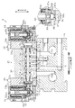
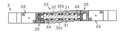
図1及び図2に示すように、電磁弁3は、上記スプール弁体21及び同スプール弁体21を往復動可能に収容する略直方体状のバルブボディ22を有する主弁部23と、バルブボディ22におけるスプール弁体21の軸方向両側に設けられる一対のパイロット弁部24及び一対の手動操作弁部25とを備えている。
Next, the configuration of the electromagnetic valve will be described.
As shown in FIGS. 1 and 2, the electromagnetic valve 3 includes a main valve portion 23 having a spool body 21 and a valve body 22 having a substantially rectangular parallelepiped shape that accommodates the spool valve body 21 so as to reciprocate, and a valve body. 22 includes a pair of pilot valve portions 24 and a pair of manually operated valve portions 25 provided on both axial sides of the spool valve body 21.

主弁部23のバルブボディ22は、スプール弁体21の軸方向両側に開口する弁孔31が形成された弁ボディ32と、弁ボディ32におけるスプール弁体21の軸方向両側にそれぞれ連結される略直方体状のピストンボディ33とを有している。弁ボディ32の弁孔31には、スプール弁体21が往復動可能に収容されている。一方、スプール弁体21には、軸方向において互いに離間するとともに圧縮エアの流路を切り換える複数の弁部21aが形成されている。各弁部21aの直径は、スプール弁体21の軸径よりも大きく形成されており、各弁部21aの外周面には、弁孔31との間をシールするパッキン34が装着されている。   The valve body 22 of the main valve portion 23 is connected to a valve body 32 in which valve holes 31 opened on both axial sides of the spool valve body 21 are formed, and to both axial sides of the spool valve body 21 in the valve body 32. The piston body 33 has a substantially rectangular parallelepiped shape. The spool valve body 21 is accommodated in the valve hole 31 of the valve body 32 so as to be able to reciprocate. On the other hand, the spool valve body 21 is formed with a plurality of valve portions 21a which are separated from each other in the axial direction and switch the flow path of the compressed air. The diameter of each valve part 21a is formed larger than the shaft diameter of the spool valve body 21, and a packing 34 that seals between the valve hole 31 is mounted on the outer peripheral surface of each valve part 21a.

図2に示すように、弁ボディ32には、給気連通流路11aに接続される給気ポート35と、第1及び第2排気連通流路12a,13aにそれぞれ接続される第1及び第2排気ポート36,37と、第1及び第2出力流路14,15にそれぞれ接続される第1及び第2出力ポート38,39が形成されている。上記各ポート35〜39は、弁孔31にそれぞれ連通するとともに、弁ボディ32におけるマニホールドベース2の載置面2aと対向する対向面32aに開口している。そして、給気ポート35は、弁ボディ32におけるスプール弁体21の軸方向中央付近に形成され、第1及び第2排気ポート36,37は、給気ポート35の両側にそれぞれ形成されている。また、第1及び第2出力ポート38,39は、給気ポート35と第1及び第2排気ポート36,37との間にそれぞれ形成されている。   As shown in FIG. 2, the valve body 32 has an air supply port 35 connected to the air supply communication channel 11a and first and second air ports connected to the first and second exhaust communication channels 12a and 13a, respectively. Two exhaust ports 36 and 37, and first and second output ports 38 and 39 connected to the first and second output flow paths 14 and 15, respectively, are formed. Each of the ports 35 to 39 communicates with the valve hole 31 and opens on a facing surface 32 a facing the mounting surface 2 a of the manifold base 2 in the valve body 32. The air supply port 35 is formed near the center in the axial direction of the spool valve body 21 in the valve body 32, and the first and second exhaust ports 36 and 37 are formed on both sides of the air supply port 35, respectively. The first and second output ports 38 and 39 are formed between the air supply port 35 and the first and second exhaust ports 36 and 37, respectively.

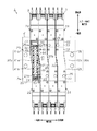
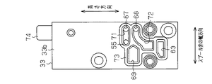
本実施形態では、図1に示すように、弁ボディ32における幅方向一端側(図1における左側)の第1側面32bは、スプール弁体21の軸方向一端側(図1における下側)よりも他端側(図1における上側)の方が弁孔31から離間するように形成されている。また、弁ボディ32における幅方向他端側(図1における右側)の第2側面32cは、スプール弁体21の軸方向他端側よりも一端側の方が弁孔31から離間するように形成されるとともに、隣接する電磁弁3の第1側面32bとスプール弁体21の軸方向において重なり合うように形成されている。つまり、弁ボディ32は、電磁弁マニホールド1の平面視で、軸方向一端側と軸方向他端側とが幅方向にずれた略クランク形状に形成されている。   In the present embodiment, as shown in FIG. 1, the first side surface 32 b on one end side in the width direction (left side in FIG. 1) of the valve body 32 is from the one end side in the axial direction (lower side in FIG. 1). Also, the other end side (the upper side in FIG. 1) is formed so as to be separated from the valve hole 31. Further, the second side surface 32 c on the other end side in the width direction (right side in FIG. 1) of the valve body 32 is formed such that one end side is separated from the valve hole 31 than the other end side in the axial direction of the spool valve body 21. In addition, the first side surface 32 b of the adjacent electromagnetic valve 3 and the spool valve body 21 are formed so as to overlap in the axial direction. That is, the valve body 32 is formed in a substantially crank shape in which the one end side in the axial direction and the other end side in the axial direction are shifted in the width direction in a plan view of the solenoid valve manifold 1.

具体的には、第1側面32bは、スプール弁体21の軸方向一端側から他端側に向かって弁孔31から離間するように所定角度で傾斜した第1傾斜面41a、及び第1傾斜面41aにおける軸方向両端に連続して設けられる同軸方向と平行な第1平行面41bから構成されている。すなわち、第1側面32bは、任意の位置での弁孔31までの距離が該任意の位置よりもスプール弁体21の軸方向一端側の位置での弁孔31までの距離以上となるように形成されている。   Specifically, the first side surface 32b includes a first inclined surface 41a inclined at a predetermined angle so as to be separated from the valve hole 31 from one end side in the axial direction of the spool valve body 21 to the other end side, and a first inclination. It is comprised from the 1st parallel surface 41b parallel to the coaxial direction continuously provided in the axial direction both ends in the surface 41a. In other words, the first side surface 32b is such that the distance to the valve hole 31 at an arbitrary position is greater than or equal to the distance to the valve hole 31 at the position on one end side in the axial direction of the spool valve body 21 from the arbitrary position. Is formed.

また、第2側面32cは、スプール弁体21の軸方向一端側から他端側に向かって弁孔31に近接するように上記第1傾斜面41aと平行に傾斜した第2傾斜面42a、及び第2傾斜面42aにおける軸方向両端に連続して設けられる同軸方向と平行な第2平行面42bから構成されている。すなわち、第2側面32cは、任意の位置での弁孔31までの距離が該任意の位置よりもスプール弁体21の軸方向他端側の位置での弁孔31までの距離以上となるように形成されている。なお、第1傾斜面41aと第2傾斜面42a、各第1平行面41bと各第2平行面42bとは、同じ大きさに形成されており、各電磁弁3の第1側面32bは、隣接する電磁弁3の第2側面32cと略全面で接するようになっている。   Further, the second side surface 32c has a second inclined surface 42a inclined in parallel to the first inclined surface 41a so as to approach the valve hole 31 from one axial end side to the other end side of the spool valve body 21, and It is comprised from the 2nd parallel surface 42b parallel to the coaxial direction continuously provided in the axial direction both ends in the 2nd inclined surface 42a. That is, the second side surface 32c is such that the distance to the valve hole 31 at an arbitrary position is greater than or equal to the distance to the valve hole 31 at the position on the other axial end side of the spool valve body 21 from the arbitrary position. Is formed. In addition, the 1st inclined surface 41a and the 2nd inclined surface 42a, each 1st parallel surface 41b, and each 2nd parallel surface 42b are formed in the same magnitude | size, The 1st side surface 32b of each solenoid valve 3 is The second side surface 32c of the adjacent electromagnetic valve 3 is in contact with the substantially entire surface.

そして、図3に示すように、弁ボディ32の載置面2aと対向する対向面32aにおいて、第1出力ポート38の開口部38aは、第1排気ポート36の開口部36aよりも第1側面32b側に膨出した形状に形成されている。また、給気ポート35の開口部35aは、第1出力ポート38の開口部38aよりも第1側面32b側に膨出した形状に形成されている。さらに、第2出力ポート39の開口部39aは、給気ポート35の開口部35aよりも第1側面32b側に膨出した形状に形成されている。つまり、載置面2a及び前面2bに開口する第1出力流路14に接続される第1出力ポート38の開口部38aは、対向面32aにおいて、第1出力ポート38におけるスプール弁体21の軸方向一端側に隣り合って配置される第1排気ポート36の開口部36aよりも第1側面32b側に膨出した形状に形成されている。   As shown in FIG. 3, the opening 38 a of the first output port 38 is located on the first side surface than the opening 36 a of the first exhaust port 36 on the facing surface 32 a facing the mounting surface 2 a of the valve body 32. It is formed in a shape that bulges to the 32b side. Further, the opening 35 a of the air supply port 35 is formed in a shape that bulges toward the first side surface 32 b than the opening 38 a of the first output port 38. Further, the opening 39 a of the second output port 39 is formed in a shape that bulges toward the first side surface 32 b than the opening 35 a of the air supply port 35. That is, the opening 38a of the first output port 38 connected to the first output flow path 14 that opens to the placement surface 2a and the front surface 2b is the shaft of the spool valve body 21 at the first output port 38 on the opposing surface 32a. It is formed in a shape that bulges toward the first side surface 32b from the opening 36a of the first exhaust port 36 that is arranged adjacent to one end side in the direction.

また、図1に示すように、弁ボディ32には、取付孔44が弁孔31の軸方向他端部に対する第1側面32b側、及び弁孔31の軸方向一端部に対する第2側面32c側にそれぞれ設けられている。そして、取付部材としての取付ネジ45が取付孔44に挿通されてマニホールドベース2のネジ孔(図示略)に螺合することにより、弁ボディ32(電磁弁3)が載置面2a上に固定される用になっている。なお、図2に示すように、マニホールドベース2と弁ボディ32との間には、載置面2aと対向面32aとの間をシールするシール部材46が介在されている。シール部材46には、各ポート35〜39の対向面32aでの開口形状と同一形状の開口部(図示略)が形成されている。   As shown in FIG. 1, the attachment hole 44 is provided in the valve body 32 on the first side surface 32 b side with respect to the other axial end portion of the valve hole 31 and on the second side surface 32 c side with respect to one axial end portion of the valve hole 31. Are provided respectively. Then, an attachment screw 45 as an attachment member is inserted into the attachment hole 44 and screwed into a screw hole (not shown) of the manifold base 2 so that the valve body 32 (electromagnetic valve 3) is fixed on the mounting surface 2a. It is intended to be used. As shown in FIG. 2, a seal member 46 is interposed between the manifold base 2 and the valve body 32 to seal between the mounting surface 2a and the opposing surface 32a. The seal member 46 is formed with an opening (not shown) having the same shape as the opening shape of the facing surfaces 32 a of the ports 35 to 39.

さらに、弁ボディ32には、スプール弁体21の位置と無関係に給気ポート35と連通する位置に開口するとともに、同弁ボディ32におけるスプール弁体21の軸方向両端面に開口する略T字状の給気通路48が形成されている。   Further, the valve body 32 opens to a position communicating with the air supply port 35 regardless of the position of the spool valve body 21, and substantially T-shaped to open at both axial end surfaces of the spool valve body 21 in the valve body 32. A shaped air supply passage 48 is formed.

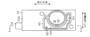
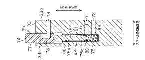
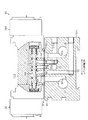
図2及び図4に示すように、バルブボディ22を構成するピストンボディ33には、弁ボディ側端面33aに開口するとともに、高さ方向に長い長穴状のピストン室52が形成されている。ピストン室52には、スプール弁体21の軸端部21bに固定されたピストン53が往復動可能に収容されている。また、図2及び図5に示すように、ピストンボディ33には、ピストン室52及びピストンボディ33のパイロット弁側端面33bに開口し、パイロット弁部24を介して給気通路48に連通する連通流路55が形成されている。そして、パイロット弁部24又は手動操作弁部25の作動状態に応じて、圧縮エアが給気通路48から連通流路55を介してピストン室52に供給され、スプール弁体21が往復動するようになっている。つまり、本実施形態の圧縮エアはパイロット流体としても機能する。   As shown in FIGS. 2 and 4, the piston body 33 constituting the valve body 22 is formed with an elongated piston chamber 52 that opens to the valve body side end surface 33 a and is long in the height direction. In the piston chamber 52, a piston 53 fixed to the shaft end portion 21b of the spool valve body 21 is accommodated so as to be capable of reciprocating. As shown in FIGS. 2 and 5, the piston body 33 communicates with the piston chamber 52 and the pilot valve side end surface 33 b of the piston body 33 and communicates with the air supply passage 48 via the pilot valve portion 24. A flow path 55 is formed. Then, in accordance with the operating state of the pilot valve portion 24 or the manual operation valve portion 25, compressed air is supplied from the air supply passage 48 to the piston chamber 52 via the communication passage 55 so that the spool valve body 21 reciprocates. It has become. That is, the compressed air of this embodiment also functions as a pilot fluid.

次に、手動操作弁部及びパイロット弁部の構成について説明する。なお、一対の手動操作弁部25及び一対のパイロット弁部24は、同様に構成されている。
図1に示すように、パイロット弁部24は、弁ボディ32との間にピストンボディ33を挟み込むように同ピストンボディ33に固定されており、手動操作弁部25は、ピストンボディ33内においてピストン室52に幅方向に並置されている。つまり、ピストンボディ33は、手動操作弁部25のボディとしても機能している。
Next, the configuration of the manually operated valve unit and the pilot valve unit will be described. In addition, a pair of manual operation valve part 25 and a pair of pilot valve part 24 are comprised similarly.
As shown in FIG. 1, the pilot valve portion 24 is fixed to the piston body 33 so that the piston body 33 is sandwiched between the pilot valve portion 32 and the manual operation valve portion 25. The chambers 52 are juxtaposed in the width direction. That is, the piston body 33 also functions as the body of the manual operation valve unit 25.

詳しくは、図1及び図6に示すように、ピストンボディ33には、その上面に開口し、高さ方向に延設される軸穴61が軸方向において取付孔44と対向する位置に形成されている。また、図6に示すように、ピストンボディ33には、軸穴61及びピストンボディ33の弁ボディ側端面33aに開口する手動給気流路62が形成されるとともに、図2に示すように、パイロット弁側端面33b及び弁ボディ側端面33aに開口するコイル給気流路63がピストン室52の下方に形成されている。図4に示すように、弁ボディ側端面33aには、手動給気流路62及びコイル給気流路63の各開口部が開口する連結凹部64が形成されている。連結凹部64は、弁ボディ32との間で手動給気流路62及びコイル給気流路63と弁ボディ32の給気通路48とを連通する流路を構成するように形成されている。なお、弁ボディ32とピストンボディ33との間には、連結凹部64を取り囲むとともに、同連結凹部64と分離させてピストン室52の開口部を取り囲むように形成されたシール部材65が介在されている。   Specifically, as shown in FIGS. 1 and 6, the piston body 33 is formed with a shaft hole 61 that opens on the upper surface and extends in the height direction at a position facing the mounting hole 44 in the axial direction. ing. Further, as shown in FIG. 6, the piston body 33 is formed with a shaft hole 61 and a manual air supply passage 62 that opens to the valve body side end surface 33a of the piston body 33, and as shown in FIG. A coil air supply channel 63 that opens to the valve side end surface 33 b and the valve body side end surface 33 a is formed below the piston chamber 52. As shown in FIG. 4, a connecting recess 64 is formed in the valve body side end surface 33 a in which the openings of the manual air supply passage 62 and the coil air supply passage 63 are opened. The connection recess 64 is formed so as to constitute a flow path that connects the manual air supply flow path 62 and the coil air supply flow path 63 to the air supply path 48 of the valve body 32 with the valve body 32. A seal member 65 is provided between the valve body 32 and the piston body 33 so as to surround the connection recess 64 and to be separated from the connection recess 64 to surround the opening of the piston chamber 52. Yes.

また、図6に示すように、ピストンボディ33には、軸穴61及びパイロット弁側端面33bにそれぞれ開口する中継流路67及びコイル出力流路68が高さ方向に間隔を空けて形成されている。さらに、図5に示すように、ピストンボディ33には、パイロット弁側端面33b及び高さ方向下側の下面に開口するコイル排気流路69が形成されている。パイロット弁側端面33bには、幅方向に延びて連通流路55及び中継流路67の各開口部がそれぞれ開口する第1連通溝71、及び幅方向に延びてコイル出力流路68の開口部が開口する第2連通溝72が形成されている。なお、ピストンボディ33とパイロット弁部24との間には、第1及び第2連通溝71,72の周囲、コイル給気流路63の開口の周囲、及びコイル排気流路69をそれぞれ取り囲むシール部材73が介在されている。   Further, as shown in FIG. 6, the piston body 33 is formed with a relay flow path 67 and a coil output flow path 68 that open to the shaft hole 61 and the pilot valve side end face 33b, respectively, at intervals in the height direction. Yes. Further, as shown in FIG. 5, the piston body 33 is formed with a coil exhaust passage 69 that opens to the pilot valve side end surface 33 b and the lower surface on the lower side in the height direction. The pilot valve side end face 33b has a first communication groove 71 extending in the width direction and having openings of the communication flow path 55 and the relay flow path 67, and an opening of the coil output flow path 68 extending in the width direction. A second communication groove 72 that is open is formed. In addition, between the piston body 33 and the pilot valve portion 24, seal members that surround the first and second communication grooves 71 and 72, the opening of the coil air supply passage 63, and the coil exhaust passage 69, respectively. 73 is interposed.

図6に示すように、軸穴61には、軸状の手動軸74が高さ方向に沿って往復動可能に収容されるとともに、手動軸74を高さ方向上側に付勢する手動バネ76が収容されている。手動軸74は、軸状の軸部75と、軸部75の上端に設けられてピストンボディ33の上面から突出する操作部77とを有している。操作部77の側面には、高さ方向に延びる係止凹部78が形成されており、同係止凹部78には、ピストンボディ33に固定されたピン79の先端が挿入されている。軸部75には、高さ方向に間隔を空けて一対の弁部75aが形成されるとともに、各弁部75aの直径は軸部75の軸径よりも大きく形成されている。なお、各弁部75aの外周面には、軸穴61との間をシールするパッキン80が装着されている。そして、各弁部75aは、係止凹部78の下端にピン79が当接する第1位置に手動軸74が位置する状態で、中継流路67とコイル出力流路68とが連通する一方、手動軸74が押圧され、係止凹部78の上端にピン79が当接する第2位置に手動軸74が位置する状態で、中継流路67と手動給気流路62とが連通するように形成されている。   As shown in FIG. 6, a shaft-like manual shaft 74 is accommodated in the shaft hole 61 so as to be able to reciprocate along the height direction, and a manual spring 76 that biases the manual shaft 74 upward in the height direction. Is housed. The manual shaft 74 has a shaft-shaped shaft portion 75 and an operation portion 77 provided at the upper end of the shaft portion 75 and protruding from the upper surface of the piston body 33. A locking recess 78 extending in the height direction is formed on a side surface of the operation portion 77, and a tip of a pin 79 fixed to the piston body 33 is inserted into the locking recess 78. The shaft portion 75 is formed with a pair of valve portions 75 a spaced apart in the height direction, and the diameter of each valve portion 75 a is larger than the shaft diameter of the shaft portion 75. In addition, the packing 80 which seals between the shaft holes 61 is attached to the outer peripheral surface of each valve portion 75a. Each valve portion 75a is connected to the relay flow path 67 and the coil output flow path 68 while the manual shaft 74 is located at the first position where the pin 79 contacts the lower end of the locking recess 78. The relay channel 67 and the manual air supply channel 62 are communicated with each other in a state where the shaft 74 is pressed and the manual shaft 74 is positioned at the second position where the pin 79 contacts the upper end of the locking recess 78. Yes.

図2に示すように、パイロット弁部24は、ピストンボディ33のパイロット弁側端面33bに固定されるパイロットボディ81を備えている。パイロットボディ81上には、ソレノイドコイル82が固定されるとともに、ソレノイドコイル82内には、プランジャ83が往復動可能に支持されている。また、プランジャ83はソレノイドコイル82のヨークを支点とするコイルバネ84aの付勢力により、ソレノイドコイル82外に向かって付勢されている。そして、ソレノイドコイル82が励磁されると、プランジャ83はコイルバネ84aの付勢力に抗してソレノイドコイル82内に向かって移動するようになっている。   As shown in FIG. 2, the pilot valve portion 24 includes a pilot body 81 fixed to the pilot valve side end surface 33 b of the piston body 33. A solenoid coil 82 is fixed on the pilot body 81, and a plunger 83 is supported in the solenoid coil 82 so as to be capable of reciprocating. The plunger 83 is urged toward the outside of the solenoid coil 82 by the urging force of the coil spring 84a with the yoke of the solenoid coil 82 as a fulcrum. When the solenoid coil 82 is excited, the plunger 83 moves toward the solenoid coil 82 against the urging force of the coil spring 84a.

図2において拡大して示すように、パイロットボディ81内には弁室85が区画されるとともに、弁室85内にはゴム製のパイロット弁体86が配設されている。弁室85において、パイロット弁体86の一端面側(図2における上側)には第1弁座85aが設けられるとともに、パイロット弁体86の他端面側(図2における下側)には第2弁座85bが設けられている。パイロット弁体86の一端面と、この一端面に対向するプランジャ83との間には、弁ガイドが設けられるとともに、パイロット弁体86の他端面と、この他端面に対向する弁室85の内面との間には、コイルバネ84bが配設されている。   As shown in an enlarged manner in FIG. 2, a valve chamber 85 is defined in the pilot body 81, and a rubber pilot valve body 86 is disposed in the valve chamber 85. In the valve chamber 85, a first valve seat 85a is provided on one end surface side (the upper side in FIG. 2) of the pilot valve body 86, and a second valve seat 85a is provided on the other end surface side (the lower side in FIG. 2). A valve seat 85b is provided. A valve guide is provided between one end surface of the pilot valve body 86 and the plunger 83 facing the one end surface, and the other end surface of the pilot valve body 86 and the inner surface of the valve chamber 85 facing the other end surface. Between them, a coil spring 84b is disposed.

また、パイロットボディ81には、第1弁座85aの内側を貫通して弁室85に開口するとともに、ピストンボディ33のコイル給気流路63に接続される給気孔87が形成されている。また、パイロットボディ81には、第2弁座85bの内側を貫通して弁室85に開口するとともに、コイル排気流路69に接続される排気孔88が形成されている。さらに、パイロットボディ81には、弁室85に開口するとともに第2連通溝72を介してコイル出力流路68に接続される出力孔89が形成されている。   The pilot body 81 is formed with an air supply hole 87 that penetrates the inside of the first valve seat 85 a and opens to the valve chamber 85 and is connected to the coil air supply passage 63 of the piston body 33. Further, the pilot body 81 is formed with an exhaust hole 88 that penetrates the inside of the second valve seat 85 b and opens to the valve chamber 85 and is connected to the coil exhaust passage 69. Further, the pilot body 81 has an output hole 89 that opens to the valve chamber 85 and is connected to the coil output flow path 68 via the second communication groove 72.

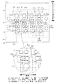
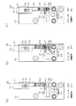
次に、電磁弁の動作について図7に従って説明する。なお、図7では、説明の便宜上、圧縮エアが供給されている領域を点ハッチングにより示す。
図7(a)に示すように、供給源からマニホールドベース2の給気流路11に圧縮エアが供給されると、電磁弁3の給気ポート35、給気通路48を介して手動給気流路62及びコイル給気流路63(給気孔87)に圧縮エアが流入する。この状態で、ソレノイドコイル82への通電が開始されると、プランジャ83がソレノイドコイル82内に移動し、第1弁座85aにパイロット弁体86が着座して給気孔87と出力孔89とが連通状態となる。すると、図7(b)に示すように、出力孔89から第2連通溝72、コイル出力流路68、軸穴61、中継流路67、第1連通溝71及び連通流路55を介してピストン室52に圧縮エアが供給される。一方、ソレノイドコイル82への通電が停止されると、第2弁座85bにパイロット弁体86が着座し、排気孔88と出力孔89とが連通状態となる。すると、排気孔88からコイル排気流路69を介してピストン室52の圧縮エアが外部に排出される。
Next, the operation of the electromagnetic valve will be described with reference to FIG. In FIG. 7, for convenience of explanation, a region where compressed air is supplied is indicated by dot hatching.
As shown in FIG. 7A, when compressed air is supplied from the supply source to the air supply passage 11 of the manifold base 2, the manual air supply passage is provided via the air supply port 35 and the air supply passage 48 of the solenoid valve 3. Compressed air flows into 62 and the coil air supply passage 63 (air supply hole 87). In this state, when energization to the solenoid coil 82 is started, the plunger 83 moves into the solenoid coil 82, the pilot valve body 86 is seated on the first valve seat 85a, and the air supply hole 87 and the output hole 89 are connected. It becomes a communication state. Then, as shown in FIG. 7B, the output hole 89 passes through the second communication groove 72, the coil output flow path 68, the shaft hole 61, the relay flow path 67, the first communication groove 71, and the communication flow path 55. Compressed air is supplied to the piston chamber 52. On the other hand, when the energization to the solenoid coil 82 is stopped, the pilot valve body 86 is seated on the second valve seat 85b, and the exhaust hole 88 and the output hole 89 are in communication with each other. Then, the compressed air in the piston chamber 52 is discharged from the exhaust hole 88 through the coil exhaust passage 69 to the outside.

また、パイロット弁部24への通電を停止した状態であっても、手動操作弁部25の手動軸74を押圧操作すると、図7(c)に示すように、手動給気流路62と連通流路55が連通状態となる。これにより、手動給気流路62から、軸穴61、連通流路55を介してピストン室52に圧縮エアが供給される。   Even when the energization of the pilot valve portion 24 is stopped, when the manual shaft 74 of the manual operation valve portion 25 is pressed, the manual air supply passage 62 communicates with the manual supply passage 62 as shown in FIG. The path 55 is in a communication state. Thus, compressed air is supplied from the manual air supply passage 62 to the piston chamber 52 through the shaft hole 61 and the communication passage 55.

そして、パイロット弁部24又は手動操作弁部25の作動に応じて、スプール弁体21の軸方向一端側のピストン室52に圧縮エアが供給されるとともに、他端側のピストン室52から圧縮エアが排出されると、スプール弁体21が軸方向他端側に移動する。これにより、給気ポート35と第1出力ポート38とが連通状態になるとともに、第2出力ポート39と第2排気ポート37とが連通状態となる。これに対し、一端側のピストン室52から圧縮エアが排出されるとともに、他端側のピストン室52に圧縮エアが供給されると、スプール弁体21が軸方向一端側に移動することで、給気ポート35と第2出力ポート39とが連通状態になるとともに、第1出力ポート38と第1排気ポート36とが連通状態となる。   Then, in accordance with the operation of the pilot valve portion 24 or the manual operation valve portion 25, compressed air is supplied to the piston chamber 52 on one end side in the axial direction of the spool valve body 21, and the compressed air is supplied from the piston chamber 52 on the other end side. Is discharged, the spool valve body 21 moves to the other axial end side. As a result, the air supply port 35 and the first output port 38 are in communication with each other, and the second output port 39 and the second exhaust port 37 are in communication with each other. On the other hand, when the compressed air is discharged from the piston chamber 52 on the one end side and the compressed air is supplied to the piston chamber 52 on the other end side, the spool valve body 21 moves to one end side in the axial direction. The supply port 35 and the second output port 39 are in communication with each other, and the first output port 38 and the first exhaust port 36 are in communication.

以上記述したように、本実施形態によれば、以下の作用効果を奏することができる。
(1)弁ボディ32の第1側面32bをスプール弁体21の軸方向一端側よりも軸方向他端側の方が弁孔31から離間するように形成するとともに、第2側面32cをスプール弁体21の軸方向他端側よりも軸方向一端側の方が弁孔31から離間するように形成した。そして、第1出力流路14に接続される第1出力ポート38の対向面32aでの開口部38aを、第1排気ポート36の対向面32aでの開口部36aよりも第1側面32b側に膨出した形状に形成した。
As described above, according to the present embodiment, the following operational effects can be achieved.
(1) The first side surface 32b of the valve body 32 is formed so that the other end side in the axial direction is separated from the valve hole 31 than the one end side in the axial direction of the spool valve body 21, and the second side surface 32c is formed as the spool valve. The body 21 was formed so that one end side in the axial direction was separated from the valve hole 31 than the other end side in the axial direction of the body 21. Then, the opening 38 a at the facing surface 32 a of the first output port 38 connected to the first output flow path 14 is closer to the first side surface 32 b than the opening 36 a at the facing surface 32 a of the first exhaust port 36. Formed into a swollen shape.

上記構成によれば、第1及び第2側面32b,32cがスプール弁体21の軸方向に対して幅方向の一端側に傾斜した形状となるため、第1出力流路14に接続される第1出力ポート38の開口部38aを、第1排気連通流路12aに接続される第1排気ポート36の開口部36aに対して幅方向一端側に大きく膨出させて形成することができる。そのため、マニホールドベース2において、各電磁弁3に対応する第1出力流路14及び第1排気連通流路12aを形成するために使用することが可能な幅方向の範囲を大きくすることができる。したがって、高さ方向視で第1出力流路14の直線部14aと第1出力ポート38の開口部38aとが重なる面積、及び第1排気連通流路12aの載置面2aでの開口面積(内径)の少なくとも一方を大きくすることができ、各電磁弁3を介して給排される圧縮エアの大流量化を図ることができる。   According to the above configuration, the first and second side surfaces 32 b and 32 c are inclined toward the one end side in the width direction with respect to the axial direction of the spool valve body 21, and therefore the first connected to the first output flow path 14. The opening 38a of the one output port 38 can be formed to bulge greatly toward one end in the width direction with respect to the opening 36a of the first exhaust port 36 connected to the first exhaust communication flow path 12a. Therefore, in the manifold base 2, the range in the width direction that can be used to form the first output flow path 14 and the first exhaust communication flow path 12a corresponding to each electromagnetic valve 3 can be increased. Therefore, the area where the linear portion 14a of the first output flow path 14 and the opening 38a of the first output port 38 overlap as viewed in the height direction, and the opening area of the mounting surface 2a of the first exhaust communication flow path 12a ( At least one of the inner diameters) can be increased, and the flow rate of the compressed air supplied and discharged via each solenoid valve 3 can be increased.

(2)取付孔44を弁孔31の軸方向他端部に対する第1側面32b側、及び弁孔31の軸方向一端部に対する前記第2側面32c側にそれぞれ設けた。上記構成によれば、弁孔31の幅方向両側における肉厚の厚い部位に取付孔44が形成されるため、同取付孔44を形成するために弁孔31の内径を小さくすることを抑制でき、各電磁弁3を介して給排される圧力流体の大流量化をより一層図ることができる。   (2) The mounting holes 44 are respectively provided on the first side surface 32 b side with respect to the other axial end portion of the valve hole 31 and on the second side surface 32 c side with respect to the one axial end portion of the valve hole 31. According to the above configuration, the attachment holes 44 are formed in thick portions on both sides in the width direction of the valve hole 31, so that the inner diameter of the valve hole 31 can be suppressed from being reduced in order to form the attachment hole 44. Further, it is possible to further increase the flow rate of the pressure fluid supplied and discharged through each electromagnetic valve 3.

(3)バルブボディ22は、弁ボディ32における軸方向両端に連結され、スプール弁体21の軸端部21bに設けられたピストン53が往復動可能に収容されるピストン室52を構成するピストンボディ33を有し、電磁弁3をピストン室52へ供給されるパイロット流体によりスプール弁体21を往復動させるパイロット形電磁弁として構成した。そして、ピストンボディ33に、手動操作によりパイロット流体のピストン室52への供給を制御する手動操作弁部25をピストン室52に対して幅方向に並置したため、電磁弁3がスプール弁体21の軸方向に大型化することを抑制できる。   (3) The valve body 22 is connected to both ends of the valve body 32 in the axial direction, and a piston body constituting a piston chamber 52 in which a piston 53 provided at the shaft end portion 21b of the spool valve body 21 is reciprocally accommodated. The solenoid valve 3 is configured as a pilot-type solenoid valve that reciprocates the spool valve body 21 with a pilot fluid supplied to the piston chamber 52. And since the manual operation valve part 25 which controls supply of the pilot fluid to the piston chamber 52 by manual operation is juxtaposed in the width direction with respect to the piston chamber 52 in the piston body 33, the electromagnetic valve 3 is the shaft of the spool valve body 21. An increase in size in the direction can be suppressed.

なお、上記実施形態は、これを適宜変更した以下の態様にて実施することもできる。
・上記実施形態では、第1及び第2側面32b,32cがそれぞれ第1及び第2平行面41b,42bを有したが、これに限らず、例えば第1側面32b及び第2側面32c全体を弁孔31に対して傾斜する形状としてもよい。また、例えば図8に示すように、第1側面32bを一端側から他端側に向かって段階的に弁孔31から離間するとともに、第2側面32cを他端側から一端側に向かって段階的に弁孔31から離間する形状としてもよい。さらに、第1及び第2側面32b,32cがスプール弁体21の軸方向に対して湾曲する形状としてもよい。
In addition, the said embodiment can also be implemented in the following aspects which changed this suitably.
In the above embodiment, the first and second side surfaces 32b and 32c have the first and second parallel surfaces 41b and 42b, respectively. However, the present invention is not limited to this, for example, the entire first side surface 32b and second side surface 32c are valved. It is good also as a shape inclined with respect to the hole 31. FIG. For example, as shown in FIG. 8, the first side surface 32b is gradually separated from the valve hole 31 from one end side to the other end side, and the second side surface 32c is stepped from the other end side to the one end side. Alternatively, the shape may be separated from the valve hole 31. Furthermore, the first and second side surfaces 32 b and 32 c may be curved with respect to the axial direction of the spool valve body 21.

・上記実施形態において、第1出力ポート38の開口部38aが第1排気ポート36の開口部36aよりも第1側面32b側に膨出した形状となれば、例えば給気ポート35の開口部35aが第1出力ポート38の開口部38aよりも第1側面32b側に膨出した形状とならなくてもよい。   In the above embodiment, if the opening 38a of the first output port 38 has a shape bulging to the first side surface 32b side of the opening 36a of the first exhaust port 36, for example, the opening 35a of the air supply port 35 However, the shape does not have to bulge toward the first side surface 32b from the opening 38a of the first output port 38.

・上記実施形態では、取付孔44を弁孔31の一端部の第1側面32b側、及び他端部の第2側面32c側に形成したが、これに限らず、他の位置に形成してよい。
・上記実施形態では、ピストン室52を高さ方向に長い長穴状に形成し、ピストン53をピストン室52と対応する楕円柱状に形成したが、これに限らず、ピストン室52を丸穴状に形成し、ピストン53を円柱状に形成してもよい。
-In the said embodiment, although the attachment hole 44 was formed in the 1st side surface 32b side of the one end part of the valve hole 31, and the 2nd side surface 32c side of the other end part, it is not limited to this and formed in another position. Good.
In the above embodiment, the piston chamber 52 is formed in the shape of a long hole that is long in the height direction, and the piston 53 is formed in the shape of an elliptic cylinder corresponding to the piston chamber 52. The piston 53 may be formed in a cylindrical shape.

・上記実施形態では、手動操作弁部25をピストン室52に対して幅方向に並設したが、これに限らず、ピストン室52に対して軸方向に並設してもよい。
・上記実施形態では、電磁弁3に2つのパイロット弁部24が設けられた所謂ダブルパイロット型のものを採用したが、これに限らず、1つのパイロット弁部のみを有する所謂シングルパイロット型のものを採用してもよい。また、電磁弁3のポートの数が3つ、あるいは4つのもの等を採用してもよい。
In the above embodiment, the manually operated valve unit 25 is arranged in the width direction with respect to the piston chamber 52, but the present invention is not limited thereto, and the manual operation valve portion 25 may be arranged in the axial direction with respect to the piston chamber 52.
In the above embodiment, a so-called double pilot type in which two pilot valve portions 24 are provided in the solenoid valve 3 is adopted, but not limited to this, a so-called single pilot type having only one pilot valve portion is adopted. May be adopted. Moreover, the number of ports of the solenoid valve 3 may be three or four.

・上記実施形態では、圧力流体として圧縮エアを用いたが、これに限らず、他の流体を用いてもよい。
・上記実施形態では、本発明を電磁弁3がパイロット流体に基づいてスプール弁体21を駆動させるパイロット形電磁弁として構成された電磁弁マニホールド1に適用したが、これに限らず、例えば電磁弁3がソレノイドコイルの励磁によるプランジャの往復動に基づいて主弁体を駆動させるものにも適用できる。
-In above-mentioned embodiment, although compressed air was used as a pressure fluid, you may use not only this but another fluid.
In the above embodiment, the present invention is applied to the solenoid valve manifold 1 in which the solenoid valve 3 is configured as a pilot-type solenoid valve that drives the spool valve body 21 based on the pilot fluid. 3 can also be applied to the case where the main valve element is driven based on the reciprocation of the plunger by excitation of the solenoid coil.

1…電磁弁マニホールド、2…マニホールドベース、2a…載置面、2b…軸方向一端側の端面としての前面、3…電磁弁、11…給気流路、11a…給気連通流路、12…第1排気流路、12a…第1排気連通流路、13…第2排気流路、13a…第2排気連通流路、14…第1出力流路、14a…直線部、15…第2出力流路、21…スプール弁体、21a…弁部、21b…軸端部、23…主弁部、24…パイロット弁部、25…手動操作弁部、31…弁孔、32…弁ボディ、32a…対向面、32b…第1側面、32c…第2側面、33…ピストンボディ、35…給気ポート、35a,36a,38a,39a…開口部、36…第1排気ポート、37…第2排気ポート、38…第1出力ポート、39…第2出力ポート、44…取付孔、45…取付部材としての取付ネジ、48…給気通路、52…ピストン室、53…ピストン、55…連通流路、61…軸穴、74…手動軸。   DESCRIPTION OF SYMBOLS 1 ... Solenoid valve manifold, 2 ... Manifold base, 2a ... Mounting surface, 2b ... Front surface as an end surface of one end side of an axial direction, 3 ... Solenoid valve, 11 ... Supply air flow path, 11a ... Supply air communication flow path, 12 ... 1st exhaust flow path, 12a ... 1st exhaust communication flow path, 13 ... 2nd exhaust flow path, 13a ... 2nd exhaust communication flow path, 14 ... 1st output flow path, 14a ... Linear part, 15 ... 2nd output Flow path, 21 ... Spool valve body, 21a ... Valve portion, 21b ... Shaft end, 23 ... Main valve portion, 24 ... Pilot valve portion, 25 ... Manually operated valve portion, 31 ... Valve hole, 32 ... Valve body, 32a ... opposing surface, 32b ... first side, 32c ... second side, 33 ... piston body, 35 ... air supply port, 35a, 36a, 38a, 39a ... opening, 36 ... first exhaust port, 37 ... second exhaust Port 38 first output port 39 second output port 44 mounting hole 5 ... mounting screw as mounting member, 48 ... supply passage, 52 ... piston chamber, 53 ... piston, 55 ... communicating passage, 61 ... shaft hole, 74 ... manual shaft.

Claims (3)

複数の流路が形成されたマニホールドベースと、前記各流路に接続される複数のポートが形成された弁ボディ及び前記各ポート間の連通を切り換える軸状の主弁体を有する複数の電磁弁と、を備え、
前記各流路の少なくとも1つは、前記マニホールドベースにおける前記電磁弁が載置される載置面及び前記主弁体の軸方向一端側の端面にそれぞれ開口し、
前記弁ボディには、前記主弁体が挿入されるとともに前記各ポートが連通する弁孔が形成され、
前記各電磁弁は、前記載置面上に前記軸方向と直交する幅方向に配列されてなる電磁弁マニホールドにおいて、
前記弁ボディにおける前記幅方向一端側の第1側面は、前記軸方向一端側よりも前記軸方向他端側の方が前記弁孔から離間するように形成されるとともに、前記弁ボディにおける前記幅方向他端側の第2側面は、前記軸方向他端側よりも前記軸方向一端側の方が前記弁孔から離間するように形成され、
前記載置面及び前記端面に開口する流路に接続される前記ポートは、前記弁ボディの前記載置面と対向する対向面での開口部が、当該ポートの前記軸方向一端側に配置される前記ポートの前記対向面での開口部よりも前記第1側面側へ膨出した形状に形成されたことを特徴とする電磁弁マニホールド。
A plurality of solenoid valves having a manifold base in which a plurality of flow paths are formed, a valve body in which a plurality of ports connected to the respective flow paths are formed, and an axial main valve body that switches communication between the ports And comprising
At least one of the flow paths opens to a mounting surface on the manifold base where the electromagnetic valve is mounted and an end surface on one end side in the axial direction of the main valve body,
The valve body is formed with a valve hole through which the main valve body is inserted and the ports communicate with each other.
In the solenoid valve manifold, each of the solenoid valves is arranged in the width direction orthogonal to the axial direction on the placement surface.
The first side surface on the one end side in the width direction of the valve body is formed such that the other end side in the axial direction is separated from the valve hole than the one end side in the axial direction, and the width in the valve body is The second side surface on the other end side in the direction is formed such that the one end side in the axial direction is separated from the valve hole than the other end side in the axial direction.
As for the said port connected to the flow path opened to the said mounting surface and the said end surface, the opening part in the opposing surface facing the said mounting surface of the said valve body is arrange | positioned at the said axial direction one end side of the said port. An electromagnetic valve manifold having a shape bulging toward the first side surface than an opening portion on the facing surface of the port.
請求項1に記載の電磁弁マニホールドにおいて、
前記弁ボディには、前記電磁弁を前記載置面上に固定するための取付部材が挿通される取付孔が前記弁孔の軸方向他端部に対する前記第1側面側、及び前記弁孔の軸方向一端部に対する前記第2側面側にそれぞれ設けられたことを特徴とする電磁弁マニホールド。
The solenoid valve manifold according to claim 1,
The valve body has a mounting hole through which a mounting member for fixing the electromagnetic valve on the mounting surface is inserted, the first side surface side with respect to the other axial end portion of the valve hole, and the valve hole An electromagnetic valve manifold provided on each of the second side surfaces with respect to one axial end portion.
請求項1又は2に記載の電磁弁マニホールドにおいて、
前記電磁弁は、前記弁ボディにおける前記軸方向両端の少なくとも一方に連結され、前記主弁体の軸端部に設けられたピストンが往復動可能に収容されるピストン室を構成するピストンボディを有し、前記ピストン室へ供給されるパイロット流体により前記主弁体を往復動させるパイロット形電磁弁として構成されたものであって、
前記ピストンボディには、手動操作により前記パイロット流体の前記ピストン室への供給を制御する手動操作弁部が前記ピストン室に対して前記幅方向に並置されたことを特徴とする電磁弁マニホールド。
The solenoid valve manifold according to claim 1 or 2,
The solenoid valve has a piston body which is connected to at least one of the axial ends of the valve body and constitutes a piston chamber in which a piston provided at the shaft end of the main valve body is reciprocally accommodated. And configured as a pilot-type solenoid valve that reciprocates the main valve body with a pilot fluid supplied to the piston chamber,
The solenoid valve manifold, wherein a manual operation valve portion for controlling supply of the pilot fluid to the piston chamber by manual operation is juxtaposed in the width direction with respect to the piston chamber.
JP2011224250A 2011-10-11 2011-10-11 Solenoid valve manifold Pending JP2013083323A (en)

Priority Applications (1)

Application Number Priority Date Filing Date Title
JP2011224250A JP2013083323A (en) 2011-10-11 2011-10-11 Solenoid valve manifold

Applications Claiming Priority (1)

Application Number Priority Date Filing Date Title
JP2011224250A JP2013083323A (en) 2011-10-11 2011-10-11 Solenoid valve manifold

Publications (1)

Publication Number Publication Date
JP2013083323A true JP2013083323A (en) 2013-05-09

Family

ID=48528706

Family Applications (1)

Application Number Title Priority Date Filing Date
JP2011224250A Pending JP2013083323A (en) 2011-10-11 2011-10-11 Solenoid valve manifold

Country Status (1)

Country Link
JP (1) JP2013083323A (en)

Cited By (4)

* Cited by examiner, † Cited by third party
Publication number Priority date Publication date Assignee Title
JP2014226547A (en) * 2013-05-22 2014-12-08 ポール・コーポレーションPallCorporation Connection system
WO2017061400A1 (en) * 2015-10-05 2017-04-13 Smc株式会社 Spool valve
WO2017061399A1 (en) * 2015-10-05 2017-04-13 Smc株式会社 Solenoid valve and manifold-type solenoid valve assembly
TWI595177B (en) * 2014-11-10 2017-08-11 Ckd Corp Solenoid valve manifold

Cited By (13)

* Cited by examiner, † Cited by third party
Publication number Priority date Publication date Assignee Title
JP2014226547A (en) * 2013-05-22 2014-12-08 ポール・コーポレーションPallCorporation Connection system
TWI595177B (en) * 2014-11-10 2017-08-11 Ckd Corp Solenoid valve manifold
US10400902B2 (en) 2015-10-05 2019-09-03 Smc Corporation Spool valve
WO2017061399A1 (en) * 2015-10-05 2017-04-13 Smc株式会社 Solenoid valve and manifold-type solenoid valve assembly
KR20180055828A (en) * 2015-10-05 2018-05-25 에스엠시 가부시키가이샤 Solenoid valve and manifold type solenoid valve assembly
CN108138980A (en) * 2015-10-05 2018-06-08 Smc株式会社 Solenoid valve and manifold-type electromagnetic valve component
WO2017061400A1 (en) * 2015-10-05 2017-04-13 Smc株式会社 Spool valve
CN108138980B (en) * 2015-10-05 2019-12-03 Smc株式会社 Solenoid valve and manifold-type electromagnetic valve component
US10544875B2 (en) 2015-10-05 2020-01-28 Smc Corporation Solenoid valve and manifold-type solenoid valve assembly
RU2722427C2 (en) * 2015-10-05 2020-05-29 ЭсЭмСи КОРПОРЕЙШН Electromagnetic valve and collector type electromagnetic valves assembly
TWI695947B (en) * 2015-10-05 2020-06-11 日商Smc股份有限公司 Spool valve
TWI698604B (en) * 2015-10-05 2020-07-11 日商Smc股份有限公司 Electromagnetic valve and manifold type electromagnetic valve assembly
KR102540683B1 (en) * 2015-10-05 2023-06-08 에스엠시 가부시키가이샤 Solenoid valve and manifold type solenoid valve assembly

Similar Documents

Publication Publication Date Title
KR101180065B1 (en) Valve body for pumps
CN108368947B (en) Manifold assembly for solenoid valve and solenoid valve assembly using the same
TWI461619B (en) Multiple manifold valve
JP2013083323A (en) Solenoid valve manifold
TWI534380B (en) High-frequency on-off valve
JP5464440B2 (en) Multiple solenoid valve
JP2015057564A (en) Multidirectional selector valve
KR20180055825A (en) Spool valve
EP1659319A1 (en) Directional control valve
KR101187454B1 (en) Reciprocating Piston Pump with Air Valve, Detent And Poppets
JPH0886380A (en) Pilot valve
US6688332B2 (en) Multiway valve for switching a flow of fluid under pressure with parallel disposition of valve bores, and valve assembly kit
KR102262070B1 (en) solenoid valve
JP2014015987A (en) Selector valve, selector valve unit, and detachable member
CN110291318B (en) Manifold base for solenoid valve and manifold type solenoid valve
US20210324961A1 (en) Spool valve
TWI595177B (en) Solenoid valve manifold
JP2605521Y2 (en) Diaphragm pump
CN110566690B (en) Solenoid valve manifold
JP5234619B2 (en) Air compressor
WO2003104695A1 (en) Solenoid valve
JP2015222107A (en) Valve device including detent member
JP4602720B2 (en) Solenoid valve manifold
JP2604658Y2 (en) Exhaust interference prevention device for manifold solenoid valve
JPH112357A (en) Pilot type solenoid valve